

Page 1

2014-01-21
Product Information PI 21.3
Disk-type tool turret
without tool drive
Series
with tool drive
Series
0.5.460.4xx
0.5.456.4xx (axial)
0.5.450.4xx (radial)
Page 2

Page 3
PI 21.3
3
Page 4

Page 5

Contens
Contens
Turret system Description........................................................................................................................................................6
Disk-type tool turret series 0.5.460.4xx
without tool drive ......................................................................................................................................................................8
Description .............................................................................................................................................................................8
Technical data ......................................................................................................................................................................10
Commodities ........................................................................................................................................................................13
Admissible loads ..................................................................................................................................................................14
Dimension ............................................................................................................................................................................16
Precision...............................................................................................................................................................................20
Disk-type tool turret series 0.5.456.4xx
with axial tool drive ................................................................................................................................................................21
Description ...........................................................................................................................................................................21
Tool configuration.................................................................................................................................................................22
Performance data at the tool coupling..................................................................................................................................23
Alternative configuration.......................................................................................................................................................25
Disk-type tool turret series 0.5.450.4xx
with radial tool drive ...............................................................................................................................................................26
Description ...........................................................................................................................................................................26
Performance data at the tool coupling..................................................................................................................................27
Dimension ............................................................................................................................................................................28
Options ....................................................................................................................................................................................29
Housing version....................................................................................................................................................................29
Arrangement of the drive......................................................................................................................................................30
Electrical connections...........................................................................................................................................................30
Working position...................................................................................................................................................................31
Type key...................................................................................................................................................................................32
Ordering details.......................................................................................................................................................................33
Please request: Project Planning Guide PA 21.3
NOTE:
The information contained in this Product Information is in conformity with the knowledge at the point of printing. Subject to
modifications which occur within the framework of continuous further development.
PI_21_3_en_2013-12-11.fm
PI 21.3
5
Page 6

Turret system description
Turret system description
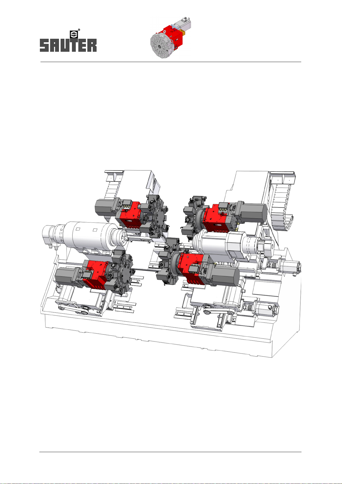
These turrets are suitable for use on high-capacity turning machines for forward as well as equipollent reverse machining. They
are equipped with all of the features and functions of modern high-performance and high-capacity tool turrets. Their robust design and short switching times mean they are also very well suited for heavy-duty use in series manufacture
Turret series
• 0.5.460.4xx without tool drive
• 0.5.456.4xx with axial tool drive
• 0.5.450.4xx with radial tool drive
Features:
• Single Motor Technology
– The turret and the tool drive share one motor; this means lower investment costs and higher level of reliability
• For equal high-performance forward and reverse machining
• Drive with standard servo or spindle motors for fast bidirectional positioning
• High degree of stability due to high locking forces
• Locking device uses special triple generating Hirth-type gear (pat.)
• Not affected by collisions due to safety clutch and annular slot for the disk tool
• Directly controllable with machine controller
• Connection with centralised lubricating system to ensure extremely high service and usage life*)
• Can be installed in any position
• Stable housing with large fastening surface ensuring high stiffness
• High thermal stability
*)
High dependance due to seal tool disk by means of sealing with air purge
6 PI 21.3
Page 7

Options:
• Air purge connection for turrets with radial tool drive
• Housing available as block or L-shaped, right and left design
• Central rotary feed-through for fluid-actuated tools and a high-pressure coolant device
• Attachment of transfer elements for switching sensors in tool disk
• Attachment of sensors to monitor cutting force
• Turrets with Y-axis slide units
• Software package for operating the system with a Siemens control Type 840-D
• Fluid rotary feedthrough
Turret system description
– The turret are available with a central rotary feedthrough
version „uncontrolled“ Feedthrough in all indexing positions
e.g. air purge, tool gripper
version „controlled“ Feedthrough in single position
e.g. coolant, tool changing
– Feed through for max. three pipelines in turret center.
pressure P
max= 100 bar (Standard)
PI 21.3
7
Page 8
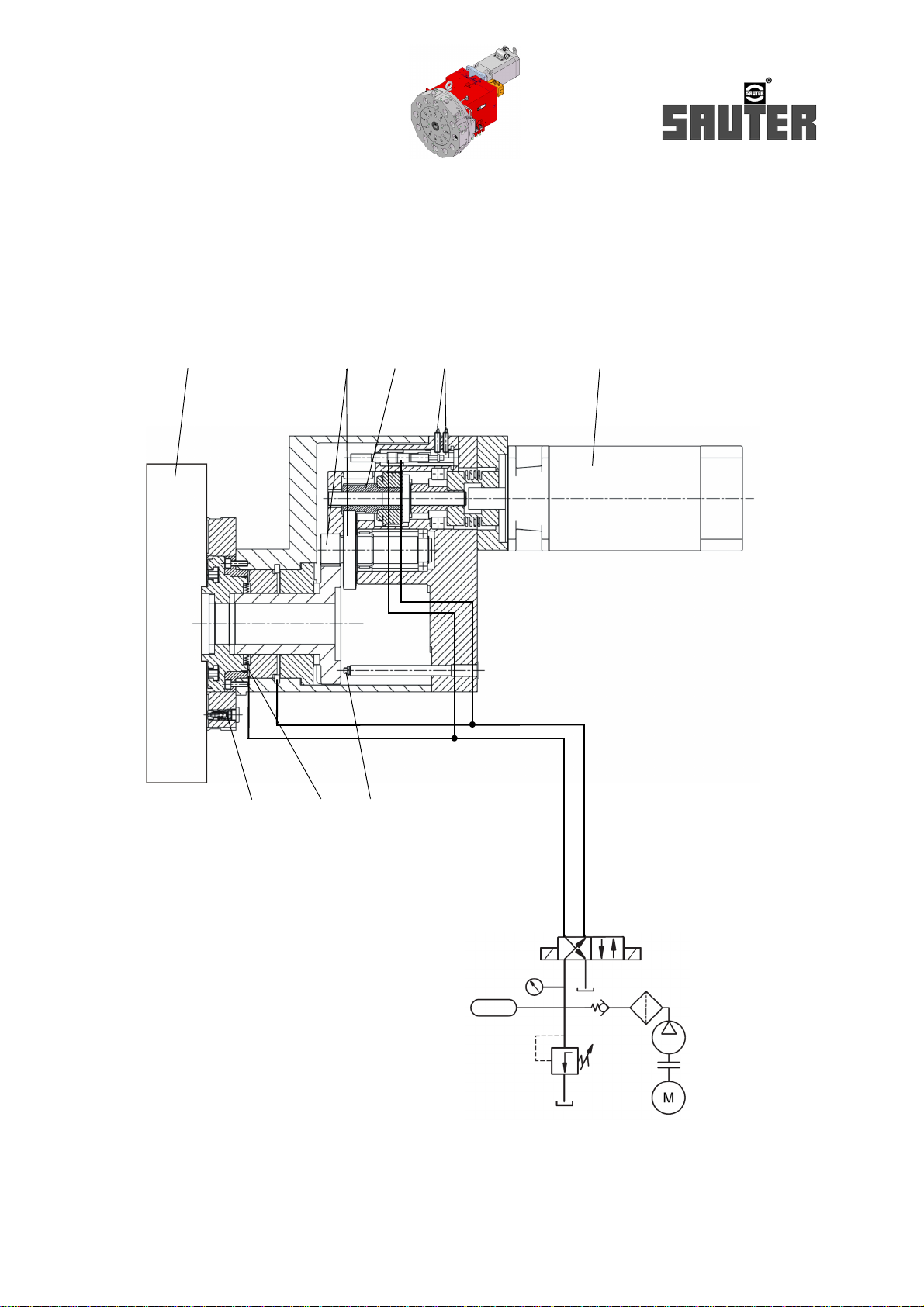
12
3
4
5
678
Hydraulics
Description
Series 0.5.460.4xx
Disk-type tool turret series 0.5.460.4xx
without tool drive
Description
8 PI 21.3
Page 9

1 Tool disk
2 Spur gear
Description
Series 0.5.460.4xx
3 Safety clutch for turret drive
4 Electrical locking control
5 Drive motor
6 Reference switches
7 Hirth-type gearing
8 Coolant valve
PI 21.3
9
Page 10
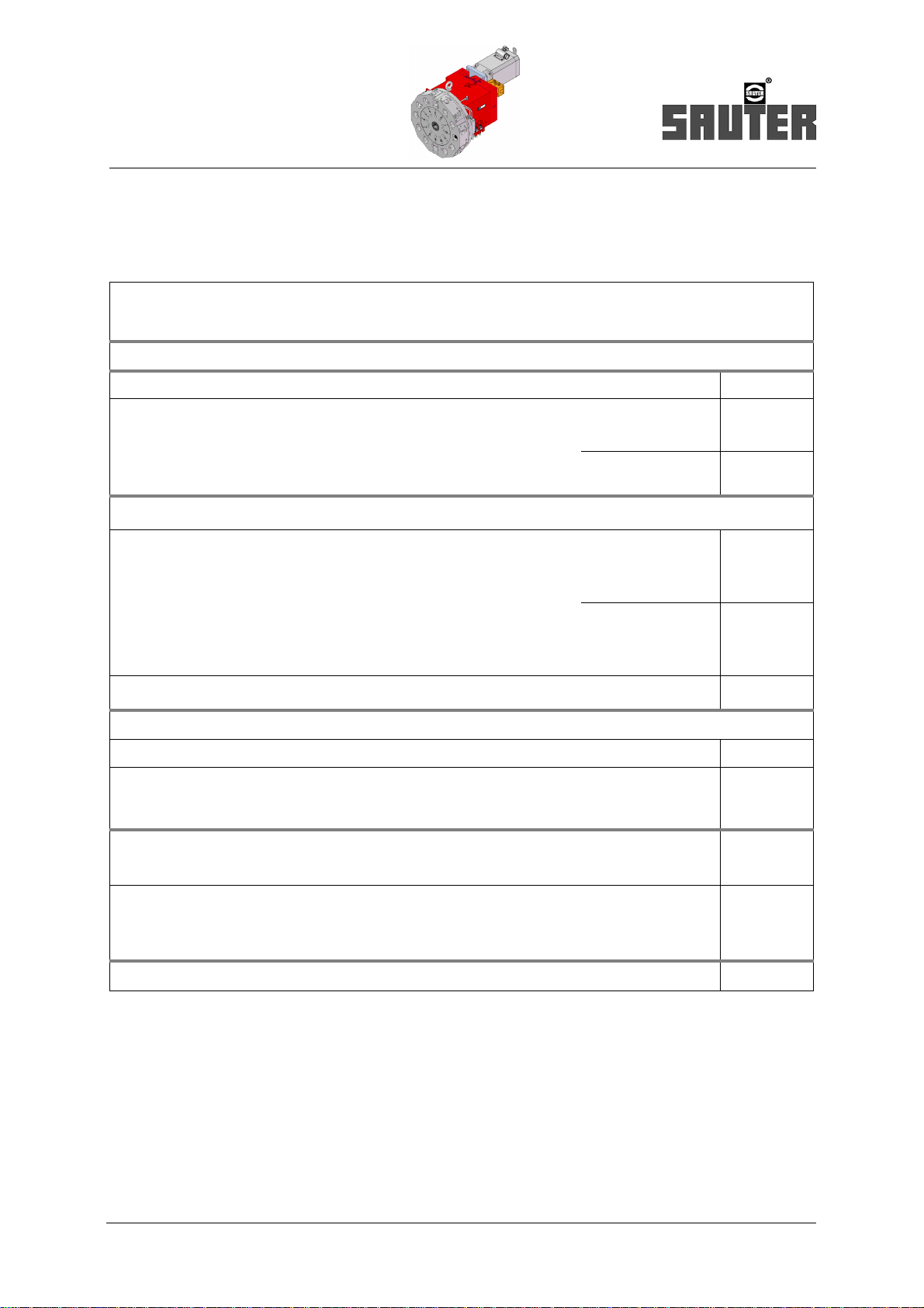
Technical data
Series 0.5.460.4xx
Technical data series 0.5.460.4xx
Series 0.5.460.4xx
Number of switching positions
Admissible tangential load (turret locked) kNm
Adm. mass moment of inertia of tools
(tool disk and holder)
Standard load stage
High load stage
kgm
kgm
2
2
Adm. out-of-balance due to tooling Standard load stage
High load stage
Indexing times
1)
Nm
Nm
Rotate tool disk
• incl. acceleration and braking per partial step Standard load stage
High load stage
• without acceleration and braking per additional partial step Standard load stage
High load stage
Turret unlock or lock (hydraulic) s
1)
Adm. indexing frequency
(median switching angle m=90°)
min
Operating pressure
Hydraulic ± 10% bar
Coolant
• with medium pressure valve
• with central high-pressure coolant device
bar
bar
Fluid absorption volume
Turret unlock/lock
cm
Mass
s
s
s
s
-1
1
1
3
• Turret (incl. standard housing,without tool disk, without motor) m
• Tool disk and tooling m
zul
Adm. ambient temperature
1) Conditions:
• Direct drive with Siemens servo motors and driving torques in accordance with the table on page 12
• Fluid supply sufficiently large
• Turret up to operating temperature
• without controller-related non-productive time
• Attention! Increased indexing times with
– higher mass moment of inertia of tool disk and toolholders
– higher mass moment of inertia of other motors
– lower driving torque
2) Ensure compliance with the required filter fineness for the tools used. For example spindle heads with internal coolant supply.
kg
kg
°C
10 PI 21.3
Page 11
Technical data
Series 0.5.460.4xx
Size
12 16 20 25 32
s 1)
0,18
0,24
0,08
0,15
min
8
12 16
8
12 16
12
1)
16
8
8
12
1)
16
0,8 1,8 3,6 7,2 12,5
0,8
1,6
12
16
0,12
0,16-0,17
0,05
0,10-0,08
0,20
0,27
0,08
0,15
1,8
4,0
25
32
0,14
0,19-0,19
0,05
0,10-0,08
0,22
0,29
0,09
0,19
3,2
6,3
40
63
0,16
0,21-0,20
0,06
0,10-0,09
0,28
0,37
0,12
0,24
8
16
80
125
0,20
0,26-0,20
0,08
0,16-0,12
0,10 0,10 0,12 0,14 0,5
-1
25 20 16 12,5 8
50
5 - 25 Filtering < 100μm
100 Filtering < 25μm
2)
2)
8
0,40
0,50
0,19
0,38
1)
12
16
25
50
160
200
0,32
0,4-0,32
0,12
0,24-0,19
1
PI 21.3
15
55
40
30 45 65 114
100
80
125
160
200
250
480
500
+ 10 ... + 40
11
Page 12

Technical data
Series 0.5.460.4xx
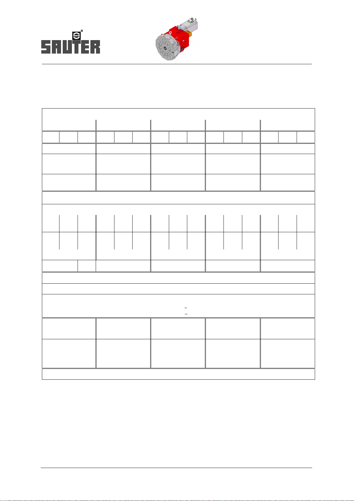
Technical data series 0.5.460.4xx
Series 0.5.460.4xx Size
12 16 20 25 32
Number of indexing positions 8 12 16 8 12 16 8 12 16 8 12 16 8 12 16
Rated speed
turret drive
Driving torque
Gear ratio i = n1 /
Recommended drive motors preferred series
Standard
load stage
High load
stage
1)
n
-1
1600 1200 - 1600 1200 - 1300 1000 - 1000 750 - 650 500 -
min
-1
min
rev
800 600 800 800 600 800 650 500 650 500 375 500 325 250 325
18 25 18 30 40 30 48 63 48 75 100 75 120 160 120
Nm
16 12 16 16 12 16 16 12 16 16 12 16 16 12 16
2)
Siemens
Servomotor
Fanuc
Servomotor
Fanuc
Spindle motor
1) Torque limitation on the motor converter!
2) The motors are not included in the SAUTER scope of supply
Other motors upon request.
1FT6.. ..064.. ..084.. ..086.. ..105.. ..108..
..
..
8/4000 is 12/4000 is 22/4000 is
..1,5 ..2 ..3 ..6 ..8
12 PI 21.3
Page 13

Commodities
Commodities
Commodities/Media
12 16 20 25 32
Hydraulic (locking)
pressure bar 50 ±10%
flow rate max. l/min 15 - 20
Coolant (Standard)
Druck bar 5 - 25 (Filtering <
Central high pressure-coolant device (Options)
pressure bar bis 100 (Filtering <
air purge (Tool disk and driven tools)
pressure bar 0,4 - 0,8
flow rate l/min ca. 6 - 10
Central lubrication (gear)
a) Oil consumption
grease consumption
(alternative)
cm
cm
3
/h
3
/24h
ca. 0,09 - 0,18
ca. 0,06 - 0,12
Size
100 μm)
25 μm)
PI 21.3
13
Page 14

Advance force ±F
z
(drilling forward and backward)
±F
z
= +Fx = 40% F
y
Size 25
Size 32
Size 20
Size 16
Size 12
Size 25
Size 32
Size 20
Size 16
Size 12
Admissible loads
Admissible loads
Note: The diagrams only apply to static loads. In the event of shock loads (discontinuous cutting) it is necessary to use significantly lower values.
Combination force ±Fy (+Fx,+Fz )
Type Turn- forward- and reverse machining
14 PI 21.3
Page 15

Shunt load +Fx
Size 25
Size 20
Size 16
Size 12
Size 32
leading edge is the basis
for dimension a
Admissible loads
PI 21.3
15
Page 16

Dimensions
Series 0.5.460.4xx
Dimensions Turret series 0.5.460.4xx ( L-shape )
16 PI 21.3
Page 17

Dimensions
Series 0.5.460.4xx
Series
0.5.460.4xx
A1 / A2
12 16 20 25 32
1)
- / 90 100 / 115 125 / 140 150 / 180 200 / -
Size
B 170 200 250 300 400
C1 / C
D1 / D
2
2
- /198 264 / 246 350 / 325 406 / 373 520 / -
- / 68 102 / 82 125 / 100 158 /125 198 / -
E2030354048
F 8 x M 8 8 x M 8 11 x M 10 11 x M 12 15 x M 12
G M 8 M 10 M 12 M 16 M20
H3240415262
Ø K 70 90 105 120 150
L
344
Siemens
359
Fanuc
373
Siemens
393
Fanuc
442
Siemens
462
Fanuc
510
Siemens
510
Fanuc
656
Siemens
M 300 345 397 445 591
N
/ N
1
2
- / 178 240 / 220 295 / 270 370 / 337 476 / -
O 68 80 100 125 160
P 120 150 185 230 300
Ø Q 175 210 255 318 396
510
Fanuc
Ø S 90 120 145 182 220
T 76 105 120 150 200
V 94 127 144 176 234
W2834404252
1) Option
PI 21.3
dimensions in mm
17
Page 18

Dimensions
Series 0.5.460.4xx
Dimensions Turret series 0.5.460.4xx ( Block-shape)
18 PI 21.3
Page 19

Dimensions
Seires 0.5.460.4xx
Series
0.5.460.4xx
A1 / A2
12 16 20 25 32
1)
- / 90 100 / 115 125 / 140 150 / 180 200 / -
Size
B 170 200 250 300 400
/ C
C
1
D1 / D
2
2
- /198 264 / 246 350 / 325 406 / 373 520 / -
- / 68 102 / 82 125 / 100 158 /125 198 / -
E2030354048
F 8 x M 8 8 x M 8 11 x M 10 11 x M 12 15 x M 12
G M 8 M 10 M 12 M 16 M20
H3240415262
Ø K 70 90 105 120 150
L
344
Siemens
359
Fanuc
373
Siemens
393
Fanuc
442
Siemens
462
Fanuc
510
Siemens
510
Fanuc
656
Siemens
M 300 345 397 445 591
N
1
/ N
2
- / 178 240 / 220 295 / 270 370 / 337 476 / -
O 68 80 100 125 160
P 120 150 185 230 300
Ø Q 175 210 255 318 396
510
Fanuc
Ø S 90 120 145 182 220
V5062657896
W2834404452
1) Option
dimensions in mm
PI 21.3
19
Page 20

Precision
Precision
Repeating accuracy
Indexing precision
(Multiple move to a switching position from the same direction)
(Multiple move to a switching position from different direction)
20 PI 21.3
Page 21

Spur gear
Driving motor
Gear case
Basic turret
working position
Coupling wheel
fluid-activated
tool coupling
Description
Series 0.5.456.4xx
Disk-type tool turret Series 0.5.456.4xx
with axial tool drive
Description
• series and a decentralized tool drive for individually switchable, axially placed tools for forwards machining.
• Hydraulic operation mode
One-motor technology:
• Turret and powered tools (spindle unit) are powered by single motor after the gear switching. Engaging and disengaging
the active tool is effected through fluid activation, after positioning of the drive spindle - no tooth on tooth situation! This
allows for quick engaging without searching. The tool coupling is designed for spindle heads with coupling toothing in
accordance with DIN 5480 and with spindle locking system.
• SAUTER-Spindle units-Type 0.5.941.xxx
• Product Information PI 29.3.
PI 21.3
21
Page 22

8 Pos.-1 reference circle
12 Pos.-1 reference circle 16 Pos.-1 reference circle
12 Pos.-2 reference circles
16 Pos.-2 reference circles
Position with tool drive
Position without tool drive
Description
Series 0.5.456.4xx
Tool arrangement
Tool arrangement:
22 PI 21.3
Page 23

Performance data at tool coupling 0.5.456.4xx
Performance data
Series 0.5.456.4xx
Size
12 16 20 25 32
2)
P
zul
M
zu
n
zu
kW
Nm
-1
min
2
4)
6
20
6000
..064-AK..
Nm
min
-1
14
6000
8/4000 is
Nm
min
-1
12
4000
1,5
Nm
min
-1
11
6000
8
32
5000
..084-AK..
28
5000
12/4000 is
18
4000
2
25
5000
10
63
4000
1,0
..086-AH..
40
4000
22/4000 is
33
4000
3
40
4000
12,5
100
4000
..105-AF..
68
4000
40/4000 is
60
4000
6
56
4000
15
160
3200
.. 108-A ..
100
3200
auf
Anfrage
70
3200
Gear performance data
Adm. driv rating
Adm. torque
Adm. rpm
Gear ratio i = n1 / n
1)
2)
1)3)
Recommended drive motors
Siemens-Servomotor, Typ 1FT6..
Max. torque
Adm. rpm
Fanuc-Servomotor, Typ
Adm. torque
Adm. rpm
Fanuc-Spindelmotor Typ
Adm. torque
Adm. rpm
1) The values are reference values for short-term operation. Higher rpms generate more heat and noise, especially when the belt drive is used!
2) Torque limitation at motor converter required! Admissible torque partially smaller than with turret drive!The listed torque values apply to smooth machining
(such as thread-cutting). In the case of machining with severe shock loads (e.g. face milling and similar operations), it is necessary to reduce the motor
drive torque by 50% or more.
3) With absolute value encoder.
4) Other motors upon request.
5) At tool coupling 40% WT – 5 min(Angaben der Motorenhersteller)
5)
5)
5)
5)
5)
5)
PI 21.3
23
Page 24

M
zul
P
zul
00
n
zul
n
zul
P
c
P
zul
n
c
n
zul
]
]
]
]
P
c
P
adm
=
n
c
n
adm
75 %
und
=
75 %
Pc = P
adm
P
c
P
adm
=
10 kW 75 %
= 7,5 kW
.
n
c
= n
adm
n
c
n
adm
=
4000 min
-1
= 3000 min
-1
.
.
75 %
und
.
]
]
]
]
Performance data
Performance data at the tool coupling
Admissible duty cycle of the tool drive during short-time operation (reference values)
Admissible duty cycle [DC] (5 min)
Admissible relative drive rating
and
Admissible relativ rpm
P
= required cutting rate [kW]
c
n
= required cutting rpm [min-1]
c
P
= Adm. drive rating [kW]
adm
n
= Adm. rpm [min-1] (see chart S. 23)
adm
100% 80% 60% 40% 25%
25% 40% 50% 75% 100%
Example calculation:
Wich speed nc and wich power Pc with 40% DC (5 min) are supported on a tool drive, size 20?
According to the table on page S. 23:
P
= 10 kW, n
Adml
Acc. to chart page 22, 40% DC:
= 4000 min-1
adml
In this example the tool drive can be operated with
P
= 7,5 kW and
c
n
= 3000 min-1
c
for 2 minutes and then it must rest for 3 minutes.
24 PI 21.3
Page 25

Ø d
1
D
K
+/- y
+/- x
Alternative configurations
Series 0.5.456.4xx
Alternative configurations type series 0.5.456.4xx
Size
Turret
version
12 Right 3°°
Working position
x / y D K
Position
+98,54 / -17
+100 / 0
+142,5 / 0
Coupling
profile
DIN 5480
14 x 0,8 25
2)
Toolholder
DIN 69880
location
Ø d
1
Dimensions
280
280
346
32
Mass
kg
(ca.)
90
90
120
1)
Max. possible tool
arrangement
(see page 22)
12 - 2
12 - 2
12 - 1
+117,4 / -25
+125 / -25
16 Right 3°°
+135 / 0
+150 / 0
+170 / 0
+155 / 0
20 Right 3°°
25 Right 3°°
32
on request
1) Overall weight of the turret incl. tool disk, without motor
2) further particulars see tool turret 0.5.461.4xx
Variants printed in bold are readily available!
Additonal variants – e.g variation „left-hand“ upon request
+170 / 0
+185 / 0
+210 / 0
+198 / -70
+200 / -20
+210 / 0
+235 / -70
+240 / 0
16 x 0,8 30
20 x 0,8 40
24 x 1,25 50
360
375
342
372
440
422
452
630
590
512
582
40
41
52
155
165
170
180
230
245
260
300
310
310
350
12 - 2
12 - 2
12 - 2
12 - 1
12 - 2
12 - 2
12 - 1
12 - 2
12 - 2
12 - 2
12 - 1
Dimensions in mm
PI 21.3
25
Page 26

Description
tool turret housing
in L- (or Block-) Form
drive motor
Gear head with
to ol co uplin g
12°°
option
Working position
9°°
3°°
Series 0.5.450.4xx
Disk-type tool turret Series 0.5.450.4xx
with radial tool drive
Description
• Basic turret series 0.5.460.4xx
• series and a centralized tool drive for individually switchable, radially placed tools for forwards and backwards machining
• Hydraulic operation mode
One-motor technology:
Turret and powered tools (spindle heads) are powered by single motor after the gear switching.
Engaging and disengaging the active tool is effected through fluid activation, after positioning of the drive spindle
– no tooth on tooth situation!
– this allows quick engaging without searching.
The tool coupling is designed for spindle heads with coupling toothing in accordance with DIN 5480 and with spindle locking
system.
see
• Sauter spindle units 0.5.941.xxx serie
• Product Information PI 29.3
26 PI 21.3
Page 27

Performance data for the tool coupling 0.5.450.4xx
Performance data
Series 0.5.450.4xx
Series 0.5.450.4xx
Gear performance data
Adm. drive rating
Adm. torque
Adm. rpm
Gear ratio i = n
1)
2)
1)3)
Recommended drive motors
Siemens-Servomotor, Typ 1FT6..
Adm. torque
Adm. rpm
Fanuc-Servomotor, Typ
Adm. torque
Adm. rpm
Fanuc-Spindle motor
Adm. torque
Adm. rpm
5)
5)
5)
5)
5)
5)
2
P
M
n
n
4)
zul
zu
Size
12 16 20 25 32
kW
Nm
zu
/
1
2
min
-1
6
20
6000
..064-AK..
Nm
min
-1
14
6000
8/6000 is
Nm
min
-1
12
6000
1,5
Nm
min
-1
11
6000
8
32
5000
..084-AK..
28
5000
12/6000 is
18
5000
2
25
5000
10
63
4000
1,0
..086-AH..
40
4000
22/4000 is
33
4000
3
40
4000
12,5
100
4000
..105-AF..
68
4000
40/4000 is
60
4000
6
56
4000
15
160
3200
.. 108-A ..
100
3000
on
request
70
3200
1) The values are reference values for short-term operation. Higher rpms generate more heat and noise, especially when the belt drive is used!
2) Torque limitation at motor converter required! Admissible torque partially smaller than with turret drive!The listed torque values apply to smooth
machining (such as thread-cutting). In the case of machining with severe shock loads (e.g. face milling and similar operations), it is necessary
to reduce the motor drive torque by 50% or more!
3) With absolute value encoder.
4) Other motors upon request.
5) At tool coupling 40% DC – 5 min
(details the engine producer)
PI 21.3
27
Page 28

Dimensions
Series 0.5.450.4xx
Dimensions Series 0.5.450.4xx
Series 0.5.450.4xx
6)
Size
12 16 20 25 32
Coupling profile DIN 5480 14 x 0,8 16 x 0,8 20 x 0,8 24 x 1,25 30x1,25
Dimensions K
P
A
Weight approx.
1)
kg 85 150 220 360 650
Toolholder system Cylinder shaft DIN 69880
32
76
48
2)
40
105
55
41
120
80
52
150
100
200
120
62
Width across flats
SW
Toolholder system Sandvik Capto
d
1
-Standard
1
3)4)
SW
2
3)4)
SW
5)
3)
25 30 40 50 60
220 270 320 380 470
240 - 360 410 -
300 340 380 - -
NG C3 C4 C5 C5 -
Width across flats
1) Overall weight of the turret incl. tool disk SW1 and without motor.
2) See SAUTER spindle units, type 0.5.941.xxx (Product information PI 29.3) and
SAUTER toolholder (Product information PI 07.2).
3) Valid for 8 and 12 tool positions / 16 tool positions on request.
4) High load load stage required.
5) See SAUTER spindle units, type 0.5.935.xxx (Product information PI 45)
Other toolholder systems – e.g. HSK – on request.
6) Further particulars see tool turret 0.5.460.4xx
SW-Standard
3)4
280 340 380 420 -
INDICATION: Instruction the operating duration (DC) see page 24.
Dimensions in mm
28 PI 21.3
Page 29

Options
Housining shape
Options
Version Left Version Right
L-shape housing
For forwards and backwards machining
with turret type 0.5.460/450
Block-shape housing
For forwards machining
with turret type 0.5.460/450
L-shape housing
For forward and backwards machining
with turret type 0.5.460/450
Block-shape housing
For forwards machining
With turret type 0.5.460/450
Block-shape housing
For forwards machining
with turret type 0.5.456
PI 21.3
Block-Form
For forwards machining
with turret type 0.5.456
Further housing shapes upon request
29
Page 30

U - 9°°
(Opt io n wi th
belt dri ve)
U - 9°°
direct (Standard)
U - 12°°
U - 3°°
U - 3°°
Redirection:
C ab le co nn ection
Co nnect ion „ top“
Co nnectio n „r ear“
Cable connection
Electrical connections:
• Terminal box (standard)
• Terminal box with round plug connectors (optional)
• Arrang ement "t op“ o r "r ear"
Options
Arrangement of the drive motor for series 0.5.460 / 456 / 450
Electrical connection for series 0.5.460 / 456 / 450
30 PI 21.3
Page 31

Working position
The working position is defined as that turret position, in which the tool is supplied with coolant and
– with turret series 0.5.456.4xx and 0.5.450.4xx - driven.
Tool location axial (Series 0.5.460.4xx, 0.5.456.4xx)
Options
Tool location radial (Series 0.5.460.4xx, 0.5.450.4xx)
PI 21.3
31
Page 32

Series
Operating medium
Size
0.5.450.4xx
0.5 . 456 . 4 20
disk-type tool turret with radial tool drive
disk-type tool turret with axial tool drive
0.5.456.4xx
disk-type tool turret without tool drive
0.5.460.4xx
4 - Hydraulics
12
16
20
25
32
Type key
Type key
1)
on request
32 PI 21.3
Page 33

Ordering details
Company:
Street:
Postal Code:
Name:
Phone:
++49 (0) 7123-926-190
++49 (0) 123-926-0
info@sauter-feinmechanik.com
Sauter Feinmechanik GmbH
Postfach 1551
D-72545 Metzingen
Germany
Fax:
E-Mail:
City
Ordering details
Ordering details Possible variants Your selection
Basic turret
Size
Number of indexing positions
Version
Housing shape
Axis height
Intended drive motor
Arrangement of the drive motor
Electrical connections
Installation on a machine
Tool drive axial
Working position
Coupling profile
Tool drive radial
Working position
Coupling profile
Disk-type tool
Toolholder systemWerkzeughalter-Toolholder
nominal size
Working position
Clamping direction (with DIN 69880)
Support pin position
Sequence of numbers
Options
Rotary feedthrough s. page 7
Special requirements:
PI 21.3
12 / 16 / 20 / 25
8 / 12 / 16
right / left
L / Block
1 / A2
A
s. page 12
direct / U-3°°/ U-9°°/ U-12°°
s. page 30
e.g. 60° at horizontal behind the
rotating axis
X / Y
s. page 25
3°° / 9°° / 12°°
s. page 25
DIN 69880 / Capto
x/y / SW
right-hand / left-hand
in front of / rear / both
right-hand / left-hand
33
Page 34

 Loading...