

Page 1
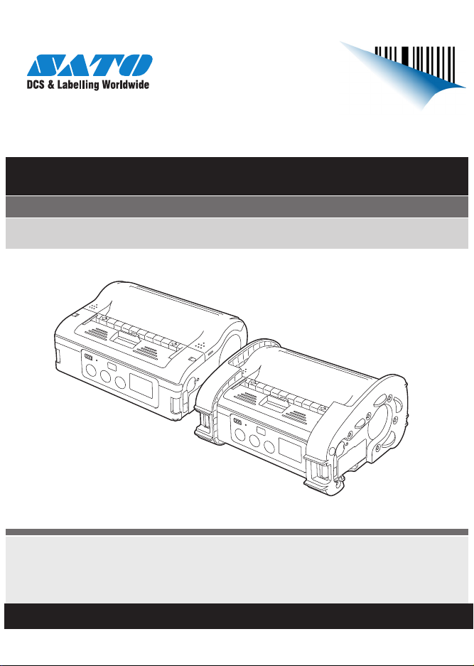
Quick Guide
For printer model:
MB400i / MB410i
www.satoworldwide.com
PN: 9001191(D)
www.satoamerica.com
Page 2

SATO America, Inc.
10350A Nations Ford Road
Charlotte, NC 28273
Main Phone: (704) 644.1650
Technical Support: (704) 644.1660
Technical Support Fax: (704) 644.1661
E-Mail: satosales@satoamerica.com
techsupport@satoamerica.com
www.satoamerica.com
Copyright 2009 SATO America, Inc. All rights reserved
Page 3

Table of Contents
Preface ..................................................................................................... 1
For the Bluetooth or wireless LAN options ...............................................1
1. Safety Precautions ..................................................... 3
Markings and Symbols ............................................................................. 3
2. Unpacking ................................................................. 12
3. Names of Parts ......................................................... 13
Names and Functions of Operating Parts ..............................................15
4. Preparing for First-time Operation ......................... 17
Charging the Battery Pack ..................................................................... 17
Installing and Removing the Battery Pack .............................................. 20
Using the AC Adapter ............................................................................. 21
Loading Labels ....................................................................................... 23
5. Turning the Power On .............................................. 31
Power ON ............................................................................................... 31
Power OFF ............................................................................................. 31
6. Test Printing .............................................................. 32
7. Operation with an RS-232C Cable ........................... 33
8. Operation with a USB Cable .................................... 34
9. Operation via Infrared Communication .................. 36
i
Page 4

10. Operation with Bluetooth or Wireless LAN .......... 38
11. Removing printed labels ........................................ 39
When the next label is not printed .......................................................... 40
12. Troubleshooting ..................................................... 41
When printing fails (automatic printing) .................................................. 44
13. Daily Care ................................................................ 46
Caring for the thermal head .................................................................... 46
Caring for the platen/dispenser roller/paper sensor ............................... 47
14. Reference ................................................................ 48
Included Items ........................................................................................ 48
Options ................................................................................................... 48
Operation Modes .................................................................................... 53
DIP Switch .............................................................................................. 61
Basic Specifications of MB400i/MB410i ................................................. 63
15. SATO Contacts ....................................................... 67
ii
Page 5

Preface
Thank you for purchasing the Barcode Printer, MB400i/410i.This manual
is created so that a first-time user of MB400i/MB410i can learn its basic
operations in a short time. Please read this manual carefully to make full
use of the functions of MB400i/MB410i.
Use this section to ensure you properly care for and use the MB400i/
MB410i printer. Read this section carefully before using your printer.
Cautions
1. Reproduction of all or part of this manual is prohibited.
2. The content of this manual is subject to change without notice.
3. This manual was created with utmost care regarding its content. However, if you find any unclear points, errors, or omissions, please contact
the dealer from whom you purchased this printer.
For the Bluetooth or wireless LAN options
Cautions regarding radio waves
This product is certified to meet technical standards based on the Radio
Law. Therefore, no wireless license is required to use this printer.
The following actions can be punishable by law:
• Disassembly or modification of this printer
• Removing the certification label (serial label) on this printer
Use in the following locations may drastically shorten the communication
distance, or prevent communication:
• Near a microwave oven
• Locations where static electricity or radio wave interference is abundant
• Near wireless LAN equipment
1
Page 6

“Bluetooth” is a registered trademark of Bluetooth SIG, Inc. USA.
Our company is using this trademark based on a licensing contract with
this association.
Before using the wireless LAN interface, be sure to set all security-related
settings for the wireless LAN equipment according to this manual.
2
Page 7
1. Safety Precautions
In this section, safety precautions about printer operation are explained to
ensure proper care and usage. Make sure to read these carefully before
using your printer.
Markings and Symbols
The following symbols or markings are used in this manual and on
the printer so that you can properly use the printer, and to prevent any
damage to property, harm or injury to yourself and others. Be sure to read
their explanations carefully to familiarize yourself with their meanings.
Warning
Caution
Symbol examples
The triangle indicates something you should take absolute care with. The cautions are indicated concretely
within the symbol. The symbol on the left indicates a
risk of electric shock.
This symbol indicates information
that, if ignored or applied incorrectly,
creates the danger of death or serious personal injury.
This symbol indicates information
that, if ignored or applied incorrectly,
creates the possibility of personal
injury or property damage.
3
Page 8
A circle with a diagonal line indicates something you
should not do. The symbol on the left indicates that you
should not try to take the unit apart.
A black circle with a picture inside indicates something
you need to do. The symbol on the left indicates that
you should unplug the unit from the wall outlet.
Specific Warnings
Liquid
Foreign Matter
Do not place any container with water or
chemicals, such as flower vase or cup, as
well as small metallic objects, near the
printer. If any of these should drop into the
printer, immediately turn off the power and
contact your nearest dealer or service center.
Continued use creates a danger of fire or
electric shock.
Do not drop or insert metallic or flammable
objects into the openings on the printer (such
as outlets for cables). If any of these should
fall into the printer, immediately turn off the
power and contact your nearest dealer or service center. Continued use creates a danger
of fire or electric shock.
4
Page 9
Dropping and Damage
Abnormal Conditions
Disassembly
Should the printer ever be dropped or otherwise become damaged, immediately turn off
the power and contact your nearest dealer or
service center. Continued use creates a danger of fire or electric shock.
Continued use of the printer while it is emitting smoke or strange odors creates the
danger of fire or electric shock. Immediately
turn off the power and contact your
nearest dealer or service center. Do not try to
service the printer by yourself.
Never try to take the unit apart or modify it in
any way. Doing so creates the danger of fire
or electric shock. Contact your nearest dealer
or service center for checking, adjustment, or
repair.
5
Page 10
Battery Pack
• Never try to take apart the battery pack or
modify it in any way such as with a solder
iron.
• Never expose the battery to direct flame,
throw it into fire, or take any actions that may
lead to shorting.
• When charging the battery pack, make sure
to use the printer or the specified battery
charger.
Warning
Warning
AC Adaptor / Battery Charger (Option)
Use only the specified voltage. Using a different voltage may create the danger of fire or
electric shock.
Use only the specified AC adapter. Using a
different one may create the danger of fire or
electric shock.
6
Page 11

Warning
Specific Cautions
Location
Never use the battery charger with any other
battery pack except for the specified one.
Doing so can rupture the battery, cause leakage, fire or electric shock.
• Never cut, damage or modify the power
cord. Also, never place heavy objects on the
power cord or heat or pull the power cord.
Doing so may damage the cord and
create the danger or fire or electric shock.
• Should the power cord ever become seriously damaged (internal wiring exposed or
shorted), contact your nearest dealer or service center for repair. Continued use of such
a cord creates the danger of fire or electric
shock.
• Never modify, excessively bend, twist, or
pull the power cord. Doing so creates the
danger of fire or electric shock.
Do not locate the printer in the area subjected
to high humidity or dew. If dew forms inside
the printer, immediately turn off the printer
and do not use it until it has been dried up.
Continued use creates the danger of electric
shock or the printer damage.
7
Page 12
Power
• Do not use wet hands to operate the power
switch, replace the battery pack or unplug the
AC adapter or battery charger. Doing so creates the danger of electric shock.
• The AC adapter set provided for this printer
is specific to this printer. Do not use it for
other electric equipment.
Thermal Head and Stepping Motor
• The thermal head gets very hot after printing. Take care when replacing the label or
cleaning the printer just after printing to avoid
burns.
• Touching the end of the thermal head with
bare hands may cause injury. Take care when
replacing the label or cleaning the printer to
avoid injury.
• Do not try to replace the thermal head by
yourself. Doing so creates the danger of
injury, burns, or electric shock.
8
Page 13
Tear-off Bar
This part contains a blade. Take care to avoid
being injured by the blade and other sharp
parts in the printer.
Replacing the Battery Pack
• Use only the specified battery pack.
• When replacing the battery pack, make sure
to install the pack in the correct orientation.
Incorrectly replacing the battery creates the
danger of injury or damage to surrounding
areas, or explosion.
• Replacing a small-size rechargeable battery
(Lithium ion battery)
Apply insulation treatment for the old battery
pack by sealing the contact with tape or the
like and ask our sales representative or service center for the measures to be taken to
recycle the reusable materials.
Do not place the battery pack together with
other batteries such as dry batteries.
9
Page 14

Leaving the printer unused for a long time
If you have no plan to use the printer for a
long time, remove the battery pack from the
printer and unplug the AC adapter from the
wall outlet.
Maintenance and Cleaning
For safe maintenance or cleaning of the
printer, make sure to remove the battery pack
and the AC adapter from the printer.
Precautions in Use
Do not place the printer in a hot or cold place.
The operation temperature range is 5° F to 122° F (-15°C to 50°C) (for
wireless LAN: 32° F to 122° F (0 to 50°C) where humidity does not cause
condensation. Do not place the printer in an area with high humidity or at a
temperature outside the specified range.
Do not drop or apply undue shock to the printer.
The printer is generally resistant to vibration possibly caused during normal transportation. However, do not apply extreme vibration or shock by
dropping the printer.
10
Page 15

Do not disassemble or modify the printer.
The printer has high-precision components inside requiring fine adjustment. Do not disassemble the printer.
Connect the correct cables to the external input terminals.
Cables of the correct specifications are required for connection to the
external equipment through the external input terminals. Contact your
nearest dealer or service center if necessary.
Use the recommended accessories.
Using optional equipment other than the specified equipment may cause a
malfunction.
Always use the equipment specified in this guide.
Use the correct media.
Use the specified media. Otherwise, faulty printing or printer damage may
occur.
11
Page 16
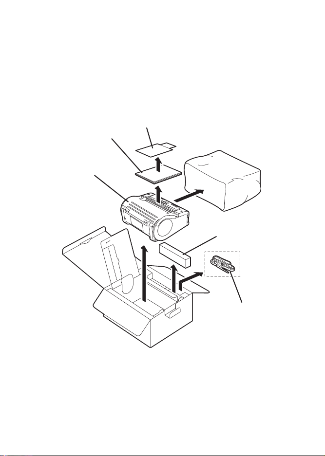
2. Unpacking
Warranty
Quick Guide
Printer unit
Battery pack
Shoulder belt
Make sure you have all the printer components shown here. If any component is missing, contact the dealer where you purchased the product from.
The appearance of any cushioning material supplied (such as protector
pads on the printer holder) may be changed across different production
batches.
12
Page 17
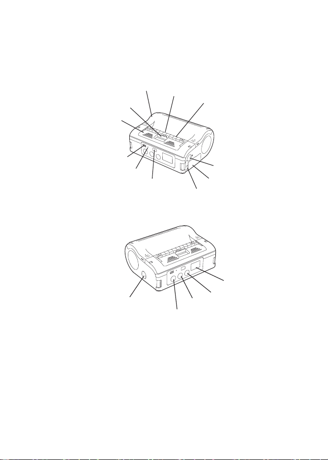
3. Names of Parts
Infrared communication sensor
STATUS (LED)
Battery life indicator
(LED) *
2
Main cover
Cover release lever
Dispenser unit
RS-232C cover
Battery cover
Label dispenser
USB/DIP switch cover
Tear-o bar
POWER button
LCD *
1
PRINT button
FEED button
DC input terminal cover
*2 On a wireless LAN interface operating panel (manufacturer option), a CHARGE
LED is provided.
*1 Only provided on wireless LAN interface operating panel (manufacturer option).
For other options, see Options in chapter 14, Reference.
Note: The MB200i and MB400i series of portable thermal printers is available in two
distinctive exterior designs. The MB400i features the use of an industrial “boot”
which helps to protect the unit in rugged and demanding industrial environments. The
MB200i product may be ordered with this boot as an option, but it is traditionally
offered without it. For expediency, this document displays the printer without a rubber boot.
13
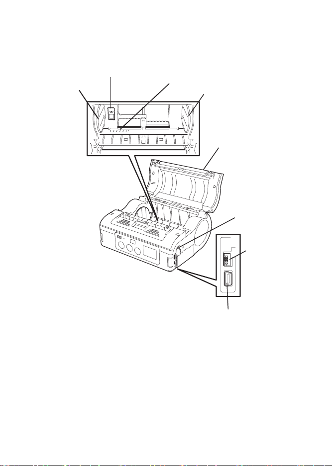
Page 18
234
4
D
1
ON
Label guide
Label width scale
Platen
Label guide stopper
DIP switch
USB connector
RS-232C connector
Label guide
110
100
908070
60
14
Page 19

Names and Functions of Operating Parts
RS-232C cover:
This covers the RS-232C connector.
RS-232C connector:
Connects with a PC etc.
USB/DIP switch cover:
Covers the USB connector and DIP
switch.
USB connector:
Connects with a PC etc.
Main cover:
Open this cover to set the labels.
Cover release lever:
Use this to release the main cover.
Tear-off bar
Cuts the printed label. Set the position of this bar for dispense mode and continuous mode.
Infrared communication sensor:
Contains an infrared receiver/transmitter element.
DIP switch:
Sets the operation mode. (See DIP Switch in chapter 14, Reference)
Dispenser unit:
Move this when using Dispense mode printing for the labels.
15
Page 20

POWER button:
Turns the power on and off.
Battery cover:
A specialized battery pack is placed inside.
Battery life indicator (LED):
Displays the available battery power.
Label guide:
Set this to match the size of the label width used.
Label guide stopper:
Press this toward the back to unlock the label guide and adjust the label guide.
Label dispenser:
Printed labels are ejected here.
Label width scale:
Use this scale to match the label width used.
DC input terminal:
Connect the AC adapter.
DC input terminal cover:
Cover for the DC input terminal.
FEED button:
Feeds the labels.
PRINT button:
Takes the printer ONLINE and OFFLINE.
STATUS (LED):
Displays the printer status. (See chapter 12, Troubleshooting, and Operation
Modes section of chapter 14, Reference.)
16
Page 21
4. Preparing for First-time Operation
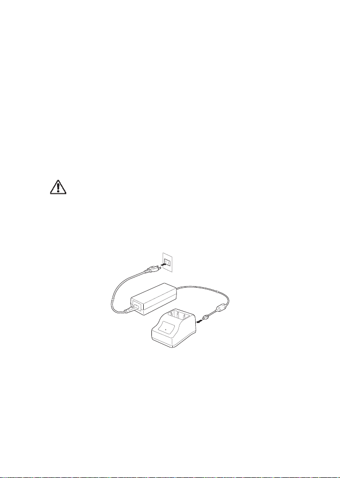
Charging the Battery Pack
Charging by installing the battery pack in the battery charger
(optional)
Install the battery pack in the battery charger (optional) and charge it.
The optional battery charger set provided for this printer is
specific to this printer. Do not use it for other electric
equipment.
1. Connect the power cord to the charger unit, then plug it into the
outlet.
When charging is complete, the CHARGE lamp lights green (fully
charged).
17
Page 22
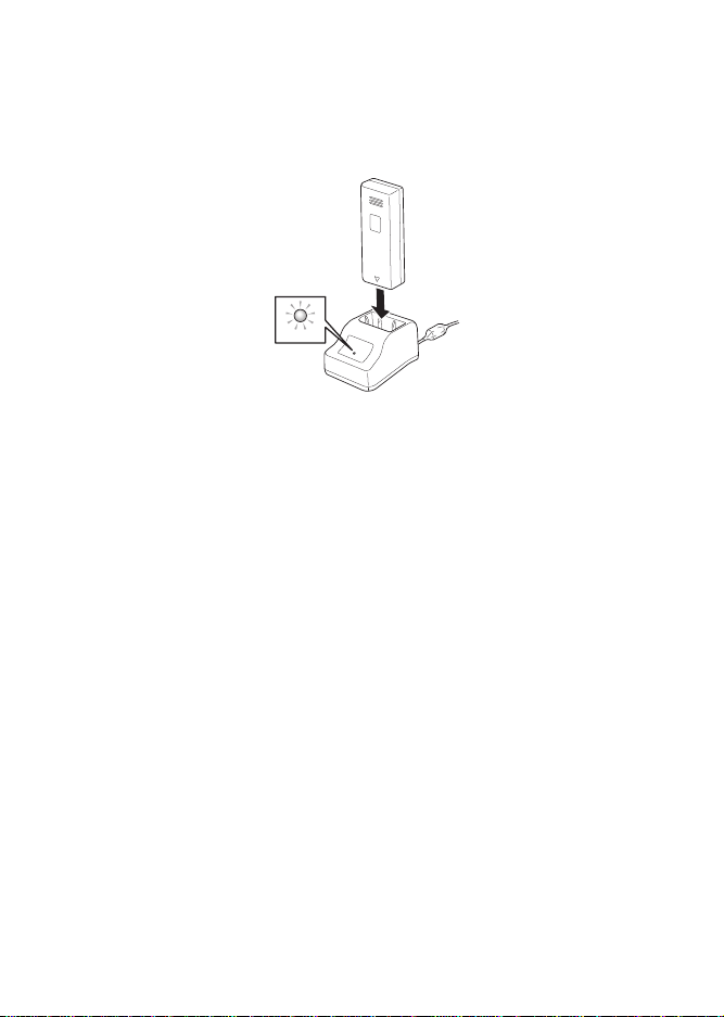
2. Insert the battery pack into the slot, with the terminal pointing down-
CHARGE
ward.
When charging begins, the CHARGE lamp (red) lights. When
charging is complete, the CHARGE lamp lights green (fully charged).
3. Remove the battery pack when charging is complete.
Charging time
It takes about 1.5 hours for the CHARGE lamp to turn off when charging a
completely depleted battery.
Notes
• When the CHARGE lamp is not lit, check that the battery pack is
installed securely. The battery may not be charged when not
securely installed.
• When a charged battery pack is installed, the CHARGE lamp first
lights red, then lights green.
18
Page 23

Charging by installing the specialized AC adapter (optional) on the
printer
This charges the battery pack while it is installed in the printer.
The AC adapter set provided for this printer is specific to
this printer. Do not use it for other electric equipment.
1. Remove the DC input terminal cover, and insert the DC output
terminal.
2. Plug the AC adapter into the outlet.
When charging begins, the battery life indicator lights red. When charging
is complete, the battery life indicator disappears (fully charged).
On a wireless LAN interface operating panel (manufacturer option), the
CHARGE LED lights red when charging begins. When charging is complete, the CHARGE LED turns off (fully charged).
Charging time
It takes about 5 hours for the battery remaining power display to turn off
when charging a completely depleted battery.
19
Page 24

Installing and Removing the Battery Pack
Terminal
Handle
1. Open the battery cover.
2. While pressing the gray hook, insert the battery pack, then
close the battery cover.
Insert the battery pack with the terminal Handle side toward the printer.
3. To remove the battery, press the gray hook to unlock it, then hold
the handle and pull out the battery.
20
Page 25

Notes:
Battery pack
Hook
• Be sure to turn the power off before removing or replacing the battery
pack. When the power is off, the STATUS LED turns off (see Power
OFF in the section, Turning the Power On). Do not remove the battery pack until this light turns off.
• Make sure to check that the STATUS LED has turned off before
removing the battery pack.
• Removing the battery pack by the operation described on the previous page may prevent updating the information in the printer memory.
Using the AC Adapter
Note:
Use AC ADAPTER: Model No.TG-5001+19v (LEAD YEAR ENTERPRISE
Co., LTD.
The AC adapter set provided for this printer is specific to
this printer. Do not use it for other electric equipment.
21
Page 26

Install the specialized AC adapter (optional) on the printer for use. The
DC output terminal
AC adapter
DC input terminal
label installation method differs by printing mode.
1. Remove the DC input terminal cover, and insert the DC output terminal
into the input terminal.
2. Connect the AC adapter to the outlet.
• Be sure to turn the printer power off before detaching the DC output
terminal for the AC adapter, or disconnecting the power supply.
• Note that disconnecting the power supply in ways other than
described above may prevent the printer from correctly storing any
settings in memory.
• No battery pack is necessary when the AC adapter is used.
• When the battery pack and AC adapter are used simultaneously,
charging begins if the battery is not fully charged. The display
becomes normal when fully charged (See the header, Charging by
installing the specialized AC adapter, optional, on the printer, in this
chapter, Preparing for First-time Operation).
22
Page 27

Loading Labels
Label paper
Journal paper
/ Linerless label
1234567
ABCDEFG
abcdefg
1234567
ABCDEFG
abcdefg
The label installation method differs by printing mode.
Continuous Printing Mode
See the printers in the figure under the header, Operation Modes, in chapter 14, Reference.
The figure below shows how labels come out of the printer in continuous
mode.
23
Page 28

1. Slide the cover release lever in the arrow direction to open the
Label guide stopper
cover. First, slide the dispenser unit to the continuous printing mode position. (See Switching from Dispense mode printing to Continuous printing
mode, in this section, Preparing for First-time Operation.)
2. While pressing the label guide stopper, slide the label guide to the label
size to be used.
24
Page 29

3. Load the paper in the printer. Make sure the roll is oriented correctly.
4. Confirm that the label roll can be rotated easily by hand.
If rotation is labored, this can cause a feed error. Remove the label roll and
adjust the label guide. Note that the label guides do not require adjustment
when you are using labels with the same width.
5. Check that the label tip is protruding. Then close the main
cover by pressing the middle of the cover. Close the main cover slowly,
while pulling the cover release lever.
This completes loading the labels for continuous printing mode.
25
Page 30

Dispense mode printing
Linerless label
with perforation
Label paper
Linerless label
n
L
per
1234567
ABCDEFG
abcdefg
abel pa
with perforatio
See the printers in the figure under the header Operation Modes, in chapter 14, Reference.
The figure below shows how labels come out of the printer in dispense
mode.
26
Page 31

1. Slide the cover release lever in the arrow direction to open the cover.
Label guide stopper
First, slide the dispenser unit to the continuous printing mode position.
(See Switching from Dispense mode printing to Continuous printing mode,
in this section, Preparing for first-time operation.)
Never slide the dispenser unit while the main cover is open.
2. While pressing the label guide stopper, slide the label guide to the label
size to be used.
27
Page 32

3. Peel the label at the tip of the label paper.
This step is unneccessary when you are using linerless labels.
4. Load the paper in the printer. Make sure the roll is oriented correctly.
28
Page 33

5. Confirm that the label roll can be rotated easily by hand. If rotation is
10mm
labored, this can cause a feed error. Remove the label roll and adjust the
label guide. Note that the label guides do not require adjustment when
using labels with the same width.
6. Check that the label tip is protruding (10 mm or more). Then close the
main cover by pressing the middle of the cover. Close the main cover
slowly, while pulling the cover release lever.
29
Page 34

7. For linerless labels with perforation, pull the label upward to tear along
the perforated line. Ensure that the tear-off edge is just at the beginning of
the red platen roller. Otherwise, re-load the label.
8. Slide the dispenser unit until it stops. If the linerless label clogs at the
dispenser, clear the label and re-load the label.
This completes loading of the labels for dispense mode printing.
Switching from Dispense mode printing to Continuous printing
mode
Grip the Tear-off bar, lift it upward slightly, and then slide it toward you.
Never pull it with the bar still engaged. This may damage the dispenser
unit.
When using dispense mode printing, be sure to follow the procedure
above to switch the dispenser unit from dispense mode printing to continuous printing mode, before changing the paper.
30
Page 35

5. Turning the Power On
POW
E
R
PRIN
T
FE
E
D
POW
ER
PRIN
T
FE
E
D
When the preparation steps are complete, turn the power on or off.
Power ON
1. Hold down the POWER button until the STATUS LED lights green. Then
release the POWER button.
Power OFF
2. Hold down the POWER button again, until the STATUS LED turns off.
Then release the POWER button.
31
Page 36

6. Test Printing
POW
ER
P
R
INT
FE
E
D
1
2
1234567
ABCDE FG
abcdefg
1234567
ABCDE FG
abcdefg
1. When pressing the FEED button and holding down the POWER button
simultaneously, the printer enters the test mode. Press the FEED button
again to start test printing.
2. Verify the following using the output of the test print.
• There are no chipped characters.
• Printing condition is good.
In test printing, the estimated remaining battery power is displayed as .
( when completely charged.) When the remaining battery power is
, charge the battery.
If a problem occurs, contact the dealer where you purchased the printer
from, or our sales personnel or service center.
32
Page 37

7. Operation with an RS-232C Cable
2341
ON
RS-232C cable
RS-232C cover
To print with an optional RS-232C cable connected to a PC or a handheld
terminal, perform the following operations.
1. Remove the USB/DIP switch cover, and set the DIP switch (DSW) to
DSW-1, 2, 3, 4 = (OFF, OFF, OFF, OFF).
2. Remove the RS-232C connector cover.
3. Insert the RS-232C cable into the connector.
Match the arrow on the RS-232C cable connector with the arrow beside
the printer connector, and insert it firmly.
4. Connect the other end of the RS-232C cable to the connector on the PC
or the handheld terminal.
For the connector on the PC or the handheld terminal, see the manuals
provided with that equipment.
33
Page 38

8. Operation with a USB Cable
2341
ON
To print with an optional USB cable (mini B type) connected to a PC or a
handheld terminal, perform the following operations.
1. Remove the USB/DIP switch cover, and set the DIP switch (DSW) to
DSW-1, 2, 3, 4 = (ON, ON, OFF, OFF).
34
Page 39

2. Insert the USB cable in the connector.
USB cover
USB cable
Match the arrow on the USB cable connector with the arrow beside the
printer connector, and insert it firmly.
3. Connect the other end of the USB cable to the connector on the PC or
the handheld terminal.
For the connector on the PC or the handheld terminal, see the manuals
provided with that equipment.
35
Page 40

9. Operation via Infrared Communica-
2341
ON
tion
To print using a Bluetooth interface or a wireless LAN interface, perform
the following operations.
1. Remove the USB/DIP switch cover, and set the DIP switch (DSW) to
DSW-1, 2, 3, 4 = (ON, OFF, OFF, OFF).
2. Place the printer within 8 inches (20 cm) of the PC or handheld terminal
for infrared communication.
36
Page 41

3. Adjust the printer position so that the PC or handheld terminal is within
30°
30°
a 30° area vertically and horizontally (cone shape) from the center of the
infrared communication sensor.
The maximum usage distance for infrared communication
is 6 to 8 inches (15 to 20 cm).
However, this differs with the usage environment and the
communicating equipment. Communication may not be
possible in direct sunlight or under powerful illumination. In such cases, either shield the infrared communication sensor from harsh light, or place the infrared
communication sensor in contact with the communicating equipment.
37
Page 42

10. Operation with Bluetooth or Wire-
2341
ON
less LAN
To print using a Bluetooth interface or a wireless LAN interface, perform
the following operations.
1. Remove the USB/DIP switch cover, and set the DIP switch (DSW) to
DSW-1, 2, 3, 4 = (OFF, ON, OFF, OFF).
Note that the effective distance varies with the usage envi-
ronment, computer, or handheld terminal in use.
38
Page 43

11. Removing printed labels
1234567
ABCDE FG
abcdefg
1234567
ABCDE FG
abcdefg
1. Data is sent from a PC.
2. When printing is complete, hold the right or left corner of the label, pull it
in the direction of the arrow, and tear the label.
The number of labels that can be printed with one battery
pack differs between continuous printing mode and dispense mode printing.
When the linerless labels are severed somewhere other
than the perforated line, and the next label is not
printed, perform the operations on the page following
this one.
39
Page 44

When the next label is not printed
12345 67
ABCDE
F
G
abcdefg
1
ABC
ab
cd
FEED button
PRINT button
1234567
ABCDE FG
abcdefg
1234567
ABCDE FG
abcdefg
1. With the printer online, press the PRINT button to take the printer offline
(STATUS LED turns off).
2. Press the FEED button to feed the labels.
3. When the paper stops, pull it in the direction of the arrow to cut the
label.
4. Press the PRINT button to put the printer online (STATUS LED lights
green).
40
Page 45

12. Troubleshooting
The status of this printer is indicated by the STATUS LED display and a
buzzer sound. When the STATUS LED display or buzzer indicates the status as described in the table that follows, the printer is in an abnormal
condition. Clear the error using the clearing method.
The printer will automatically turn off in about 30 seconds after a low battery display appears. Confirm that the power is off, then remove the battery pack and charge it.
41
Page 46

STATUS LED/buzzer Mode Content -->
LED: ON (red) All modes Low battery A
LED: Blinking (red) every 2
seconds
Buzzer: One long beep
LED: ON (red) After turning
LED: Two colors blinking alternately (green --> red) every 2
seconds.
Buzzer: One long beep
LED: Blinking (red) every 0.5
seconds. Buzzer: Three short
beeps.
LED: Blinking (green) every 1
second.
Buzzer: One long beep.
LED: Blinking (green) every 0.5
seconds.
Buzzer: One long beep.
LED: Blinking (red) every 4
seconds
Buzzer: One long beep
LED: Blinking (green) every 2
seconds
LED: Patterned lighting (red +
OFF + green --> OFF) every 1
second
LED: Two colors blinking alternately (green-->orange) every
0.5 seconds
Online Module error (Blue-
power on
Online Head error D
Online Cover open E
Online Communication error H
Online (printing or receiving data)
Online (priniting or receiving data)
All modes Sleep mode K
All modes Head overheating
Online (automatic dispenser printing
or dispenser
operation 2)
tooth or wireless LAN)
1 Program abnormality error
2 FLASH ROM error
Out of paper F
Sensor error G
Buffer almost full I
Buffer overvlow J
protection function
Manual dispensing
mode
B
C
L
M
42
Page 47

--> Cause Clearing Method
A 1 The battery is not fully charged. 1 Charge the battery.
B 1 Interface module is in abnormal
condition, (Bluetooth or wireless
LAN)
C 1 A FLASH ROM reading/writing
error has occured.
D 1 The head has a broken wire. 1 Replace the head.##
E 1 The cover is not locked.
2 Cover opening/closing sensor is in
abnormal condition.
F 1 Out of labels. 1 Set a new roll of labels.
G 1 The sensor level is incorrect.
2 The sensor type is incorrect.
3 The paper is misrouted.
H 1 The communication conditions are
incorrect.
2 Cable connection is in abnormal
condition.
I 1 The receiving buffer is running out
of capacity.
J 1 Data has exceeded the receiving
buffer capacity.
2 The communication conditions are
incorrect.
K 1 This is not an error.
The printer is operating in low power
consumption mode.
L 1 This is not an error.
The head overheating protection
function operates when the head
temperature exceeds 70°C.
M 1 This is not an error.
2 Press the PRINT button to print
one label.
## Contact your nearest service center or dealer.
1 Replace the board. ##
1 Replace the FLASH ROM.##
2 Re-download the program.##
1 Lock the cover.
2 Adjust the sensor.##
1 Adjust the sensor level.##
2 Match the sensor type.
3 Remove & correctly place label roll.
1 Correct the communication conditions.
2 Check the cable connections.
1 Pause host data transmission, wait
for the buffer to empty, then retransmit data.
1 Transmit data corresponding with
the communication conditions.
2 Correct the communication conditions.
1 Clear by pressing a button, receiving
data, or opening/closing the main
cover.
1 This is cleared when the head temperature falls to 55°C.
1 Automatically cleared when the designated number of labels are printed.
43
Page 48

When printing fails (automatic printing)
In direct sunlight or under illumination, the internal sensors may mis-operate (assuming a label is present in the dispenser unit), and prevent printing. In such malfunction, either shield the dispenser unit from harsh light,
or operate using one of the following methods.
1. Operation using manual printing
Switch to manual printing by specifying the dispenser operation mode.
(See Charging the dispense mode printing setting in Operation Modes
section of chapter 14, Reference.)
2. Operate using operation 2 for the dispenser operation
Using the printer setup tool, switch the dispenser operation to operation 2.
When operation 2 is set for the dispenser operation, if harsh light is preventing printing, print using the following procedure.
Press the PRINT button to switch to manual printing, and print one label.
When printing multiple labels, operate with manual printing until the designated number of labels are printed.
While operating in manual printing mode, the STATUS LED alternates
between lighting green and orange (every 0.5 seconds).
Print condition Causes Countermeasure
Smudged 1 The head is dirty
2 The rollers are dirty
1 Clean the head (See Caring for the
thermal head section in chapter 13 Daily
Care).
2 Clean the platen (See Caring for the
platen/dispenser roller/paper sensor in
chapter 13, Daily Care).
44
Page 49

Print condition Causes Countermeasure
Vertical stripes 1 The head is dirty
Characters
printing diagonally
Blank (not
printed)
## Contact your nearest service center or dealer.
2 The head is defective
1 The label guide position is
incorrect
2 The rollers are dirty
1 The RS-232C/USB cable
connection is poor
2 Infrared communication
error
3 Bluetooth/wireless LAN
communication error.
4 The DIP switch settings
are incorrect
5 The head is defective
1 Clean the head (See Caring for the
thermal head section in chapter 13 Daily
Care)
2 Replace the head ##
1 Reset the label (See the Loading
Labels section of chapter 4 Preparing for
First-time Operation).
2 Clean the platen (See Caring for the
platen/dispenser roller/paper sensor in
chapter 13, Daily Care).
1 Check the RS232C\USB cable connections (See section, Operation with an
RS-232C Cable, chapter 7, or section,
Operation with a USB Cable, chapter 8.)
2 The distance between the PC and the
printer should be within 6-8 inches (1520 cm.). In addition, check that the PC
is within a 30 degree area vertically and
horizontally (cone shaped) from the center of the printer infrared communication
sensor (See chapter, Operation via Infrared Communication).
3 Check all settings.
4 Check the DIP switch settings (See the
DIP Switch section of chapter 14, Reference).
5 Replace the head. ##
45
Page 50

13. Daily Care
Thermal head
Be sure to turn the power off and remove the battery pack before performing the following operations.
Caring for the thermal head
1. Slide the cover release lever to open the cover.
When in dispense mode printing, first slide the dispenser unit to the continuous printing mode position. (See section, Switching from Dispense
mode printing to Continuous printing mode, in chapter 4, Preparing for
First-Time Operation.)
2. Wipe off any smudges with a cloth dipped in alcohol.
Do not use thinner, benzene, or kerosene.
46
Page 51

Caring for the platen/dispenser roller/paper
Platen
Paper sensor
Dispenser roller
sensor
1. Slide the cover release lever to open the main cover.
When in dispense mode printing, first slide the dispenser unit to the continuous printing mode position. (See section, Switching from Dispense
mode printing to Continuous printing mode, in chapter 4, Preparing for
First-Time Operation.)
2. Wipe off any smudges with a cloth dipped in alcohol. Do not use thinner, benzene, or kerosene.
47
Page 52

14. Reference
Included Items
Shoulder belt
This belt allows you to carry the printer on your shoulder.
1. Thread the shoulder belt through the belt holes on the printer, from the outside to the inside.
2. Thread the end of the shoulder belt through the buckle, and adjust the length. If the belt is not routed correctly, the belt may detach and the printer may drop.
Options
User options
Battery pack (one pack provided with this printer)
Having extra batteries available will minimize work interruptions caused by
depleted batteries.
48
Page 53

Battery charger (single)
This charges a single battery pack.
AC adapter for printer
Use this to supply power from a household power outlet (AC100V or
240V).
Connect the DC output terminal of the AC adapter to the printer.
• Be sure to use the specified adapter.
• Hold the printer when connecting or disconnecting.
• Be careful not to damage the cord.
• Unplug for storage when not in use.
• The AC adapter set provided for this printer is specific to this
printer. Do not use it for other electric equipment.
49
Page 54

Case with rain-resistant cover
You can buy a Waist case or a case that hangs from the shoulder. The
shoulder case is a version of the Waist case that has a rain-resistant
cover. You can use these cases only with the model without the rubber
boot.
Fastening method
1. Open the cover and place the printer in it with the operating parts facing up.
2. Place the lower side in the case so that the printer is completely in the case.
3. Close the cover.
50
Page 55

4. Affix the rain-resistant cover to the Waist case with the buttons and set
Rain-resistant cover
Waist case
Shoulder strap
in place.
5. Attach the shoulder strap to the case.
Waist case - Does not fit over rubber boot
This protective case is for carrying the printer by attaching it to your belt.
Fastening method
1. Open the cover and place the printer in it with the operating parts facing up.
51
Page 56

2. Place the lower side in the case so that the printer is completely in the case.
3. Close the Waist case cover.
4. Run a belt through the Waist case loops.
RS-232C cable
This connects with a PC or handheld terminal.
USB cable
This connects with a PC or handheld terminal.
Manufacturer options
Wireless LAN interface operating panel (with LCD)
This is an operating panel with an LCD to display the wireless communiction status.
52
Page 57

Operation Modes
1234567
ABCDEFG
abcdefg
1234567
ABCDEFG
abcdefg
1234567
ABCDEFG
abcdefg
1234567
ABCDEFG
abcdefg
Continuous printing
Dispenser printing
(label paper)
Dispenser printing
(non-separated labels)
Test printing
Continuous printing
Dispenser printing
Online printing
Continuous printing
Dispenser printing
Prints the printer status
(Receives data from a PC or
handheld terminal and prints it)
1234567
ABCDEFG
abcdefg
1234567
ABCDEFG
abcdefg
1234567
ABCDEFG
abcdefg
Continuous printing
Dispenser printing
(label paper)
Linerless labels
Test printing
Continuous printing
Dispenser printing
Online printing
Continuous printing
Dispenser printing
Prints the printer status
(Receives data from a PC or
handheld terminal and prints it)
1234567
ABCDE F
G
abcdefg
1
A
B
C
ab
c
d
1234567
ABCDEFG
abcdefg
1234567
ABCDEFG
abcdefg
1234567
ABCDEFG
abcdefg
Continuous printing
(label paper/linerless label/
Journal paper)
Dispenser printing
(label paper)
Dispenser printing
(Linerless label with
perforation)
Test printing
Continuous printing
Dispenser printing
Online printing
Continuous printing
Dispenser printing
Prints the printer status
(Receives data from a PC or
handheld terminal and prints it)
1234567
ABCDE F G
abcdefg
1
A
B
C
a
b
c
d
There are two printer operation modes: continuous printing mode, and dispense mode printing. Test printing and online printing are available in both
modes.
Use the printer setting tool to set dispense mode printing (linerless labels
with perforation).
53
Page 58

Normal operation mode
The LED display for the normal operation mode is as follows.
Operation status STATUS (LED)
Starting normal printing mode
Online ON (green)
Offline OFF
ON (orange)
When the buzzer sound mode is enabled, the buzzer sounds upon
startup.
The battery life indicator remains on even when the printer is OFFLINE.
Power saving mode
1. Sleep mode:
With the printer is online, the STATUS (LED) blinks (green) every two seconds. When offline, the STATUS (LED) is off. The battery life indicator
(LED) remains on even when the printer is OFFLINE.
The printer enters sleep mode (standby status) when it has not been operated for five seconds.
Normal status is resumed by pressing the PRINT button or the FEED button, by receiving data, or by opening and closing the main cover.
54
Page 59

Test printing mode (FEED button + POWER ON)
When the buzzer sound mode is enabled, the buzzer sounds upon
startup. Release the FEED button to stop the buzzer.
55
Page 60

Dispense mode printing
(1) Automatic dispenser printing setting
DSW-1,2,3,4=(OFF,OFF,OFF,ON) + cover open+ PRINT button + POWER
(2) Manual dispenser printing setting
DSW-1,2,3,4=(OFF,OFF,OFF,ON) + cover open + FEED button + POWER
Processing dispenser operation mode setting
(STATUS LED flashes green)
Setting completes
(STATUS LED lights green)
Dispense mode printing setting
Type Operation Default
Automatic
printing setting
Manual printing
setting
Prints one label after receiving data, then waits for
label to be peeled. After the label is peeled, the next
label is printed automatically.
Prints one label after receiving data, then enters
offline status. When the PRINT button is pressed, the
next label is printed. After the specified number of
labels are printed, printing is ended, and no labels are
printed when the PRINT button is pressed.
Changing the dispense mode printing setting
The dispenser operation mode setting is changed by the DIP switch
(DSW) settings when the power is turned on, and by button settings. The
settings are enabled upon turning the power off.
Notes: When the buzzer sound mode is enabled, the buzzer sounds upon
startup.
Release the PRINT/FEED button to stop the buzzer.
To end the dispenser operation mode setting, confirm that the STATUS
LED is on in green, then turn the power off. After changing the dispenser
operation mode setting, be sure to restore the DSW to their original settings.
Manual printing
setting
56
Page 61

Head check setting mode
Setting head check function
(STATUS LED flashes green)
Setting completes
(STATUS LED lights green)
DSW settings (A/B) + cover open + PRINT/FEED button + POWER
In the head check setting mode, a check can be performed in two checking areas: the printing area and the barcode printing area.
The presence of the head check function and the head check range settings are set by the DIP switch (DSW) settings when the power is turned
on, by button pressing status, and by the cover status.
DIP switch settings
(A) OFF ON OFF ON
(B) ON OFF OFF ON
DSW
settings
(A) PRINT button + cover open Head check range set as
(B) PRINT button + cover open Head check range set as bar-
Note:
When the buzzer sound mode is enabled, the buzzer sounds upon startup.
Release the PRINT/FEED button to stop the buzzer. To check the settings for head
check setting mode, see the test print output (See chapter 6, Test Printing).
To end head check setting, confirm that the STATUS LED is on in green, then turn
power off. After changing the head check setting mode, be sure to restore the DSW
to their original settings.
DSW-1 DSW-2 DSW-3 DSW-4
Button and cover
status
FEED button + cover open Head check function set as
FEED button + cover open Head check function set as
Function Default
printing area
disabled
code printing area only
Head
check
range
set as
printing
area
disabled
57
Page 62

Online command setting mode
Processing setting
(STATUS LED flashes green )
Settings complete
(STATUS LED lights green )
(1) MB400 compatibility command setting
DSW-1,2,3,4=(ON,ON,ON,O N) + cover open + PRINT button + POWER
(2) SBPL command setting
DSW-1,2,3,4=(ON,ON,ON, ON) + cover open + FEED button + POWER
Online command setting details
Type Operation Default
MB400 compatibility
command setting
SBPL command setting
Sets the online command as standard
legacy command (of theMB200/400
series).
Sets the online command as an SBPL
command.
Change online command setting
The online command setting is changed by the DIP switch (DSW) settings
when the power is turned on, and by button settings. The settings are
enabled upon turning the power off.
Note:
When the buzzer sound mode is enabled, the buzzer sounds upon
startup.
Release the PRINT/FEED button to stop the buzzer. To check the settings
for head check setting mode, see the test print output (See Section 6, Test
Printing).
To end head check setting, confirm that the STATUS LED is on in green,
then turn power off. After changing the head check setting mode, be sure
to restore the DSW to their original settings.
SBPL command setting
58
Page 63

Buzzer sound mode setting
Processing setting
(STATUS LED flashes gr een)
Setting completes
(STATUS LED lights green)
(1) D isable buzzer sound
DSW-1,2,3,4=(OFF,OFF,ON,ON) + cover open + PRINT button + POWER
(2) E nable buzzer sound
DSW-1,2,3,4=(OFF,OFF,ON,ON) + cover open + FEED button + POWER
A buzzer can be sounded upon starting up the printer and upon errors.
The buzzer is enabled by default. This can be enabled or disabled by the
initial operation and by online command.
Change buzzer sound setting
Note:
When the buzzer sound mode is enabled, the buzzer sounds upon
startup.
Release the PRINT/FEED button to stop the buzzer. To check the settings
for the buzzer sound setting mode, see the test print output (See P. 23).
To end buzzer sound setting, confirm that the STATUS LED is on in green,
then turn the power off. After changing the buzzer sound setting mode, be
sure to restore the DSW to their original settings.
59
Page 64

Standard/non-standard code setting mode
Processing setting
(STATUS LED flas hes green)
Setting completes
(STATUS LED lights green)
(1) Non-standard code setting
DSW-1,2,3,4=(ON,ON,OFF,ON) + cover open + PRINT button + POWER
(2) Standard code setting
DSW-1,2,3,4=(ON,ON,OFF,ON) + cover open + FEED button + POWER
Standard/non-standard code settings for control codes can be changed using the
control code setting command.
Standard/non-standard specifications
Type Operation Default
Standard
code
setting
Non-standard code
setting
The following control codes are set as standard codes. Standard
Control code Binary
STX 02H
ETX 03H
ESC 1BH
ENQ 1BH
CAN 18H
NULL 00H
The following control codes are set as non-standard codes.
Control code Binary
STX 7BH({)
ETX 7DH())
ESC 5EH(^)
ENQ 40H(@)
CAN 21H(!)
NULL 7EH(~)
Non-standard codes can be changed using the user download setting command.
Change standard/non-standard code setting
The standard code/non-standard code setting is changed by the DIP switch (DSW)
settings when the power is turned on, and by button settings. The settings are
enabled upon turning the power off.
Notes: When the buzzer sound mode is enabled, the buzzer sounds upon startup.
Release the PRINT/FEED button to stop the buzzer. To check the setting for the
standard code/non-standard code setting mode, see chapter 6, Test Printing. To end
standard code/non-standard code setting, confirm that the STATUS LED is on in
green, then turn power off. After changing the standard code/non-standard code setting mode, be sure to restore the DSW to their original settings.After changing the
dispenser operation mode setting, restore the DSW to their original settings.
60
code
setting
Page 65

DIP Switch
2341
ON
Setting DIP switch
1. Turn the power OFF.
2. Open the DIP switch cover.
3. Use a pointed object, such as the tip of a ballpoint pen, to change the switch position.
61
Page 66

DIP Swith setting items
DIP Switch Cover Key Startup Mode
1234 PrintFeedInterface Content
OFFOFF OFFOFFclose OFF OFF RS-2C Normal printing mode
OFFOFF ON ON close OFF OFF RS-2C HEX dump mode
OFFOFF OFFON open ON OFF - Set Automatic peeling printing
OFFON OFFOFF close OFF OFF Bluetooth
OFF ON OFFON open ON OFF - Head check (printing area)
OFFONONONclose OFFOFFBluetooth
ON OFFOFFOFF close OFF OFF Infrared
ON OFFON ON close OFF OFF Infrared
ON OFFOFFON open ON OFF - Head check (Barcode printing
ON ON OFFOFFclose OFF OFF USB interface Normal operation
ON ON ON ON close OFF OFF USB interface HEX dump mode
ON ON OFFON open ON OFF - Non-standard Control codes
close OFF ON - User test printing mode
open ON OFF - Buzzer sound disabled
open OFF ON - Buzzer sound enabled
open OFF ON - Set Manual peeling printing
interface
Wireless LAN
close OFF ON - User test printing mode
open OFF ON - Head check disabled
open ON OFF - CRC check enabled
open OFF ON - CRC check enabled
close OFF ON - Test printing mode
open OFF ON - Head check disabled
close OFF ON - Test printing mode
open ON OFF - Set compatibility with MB400
open OFF ON - Set compatibility with SBPL
open OFF ON - Standard Control codes
interface
interface
Wireless LAN
interface
interface
interface
Normal printing mode
setting
HEX dump mode
Normal startup mode
HEX dump mode
area) setting
Online Commands
Online Commands
62
Page 67

Basic Specifications of MB400i/MB410i
Item MB400i MB410i
Printing method Thermal printing
Head density 8 dots/mm (203 dpi) 12 dots/mm (305 dpi)
Maximum effective
printing area
Printing speed Maximum 4”/sec (103 mm/sec) [printing speed is 3”/sec
Dimensions
• MB400i/410i without
rubber boot
Dimensions
• MB400i/410i with rubber boot
Weight
• MB400i/410i without
rubber boot
Weight
• MB400i/410i with rubber boot
Power source [battery] Pack type [lithium ion] 1700 mAh can continuously print
4.09” (104 mm) [width] × 11.69” (297 mm) [pitch]
(75 mm/sec) during dispenser printing]. The speed differs, depending on printing duty and usage
environment.
Printing speed can be changed using the printing speed
setting command.
Printer: 6.7” (170 mm) [width] × 3” (76 mm) [depth] ×
5.3” (134 mm) [height]
Printer: 8” (202 mm) [width] × 3.9” (99 mm) [depth] ×
6.5” (165 mm) [height]
1.65 lbs (750 g) or less [Standard model, including battery pack]
2 lbs (910 g) [Standard model, including battery pack]
four rolls of thermal labels [equivalent to 164 ft (50 m)]
when fully charged [however, at a printing rate of 16% or
less].
63
Page 68

Item MB400i MB410i
Paper
Paper thickness
Paper shape
Label size [backing
liner and I-mark pitch]
Label printing Continuous printing (Paper sensor enabled)
Self-diagnosis function Head check/battery check/paper end/cover open/test
Always use genuine SATO labels.
2.5 Mil to 7.5 Mil (0.064 mm to 0.190 mm)
Roll media: Face-out winding
Maximum outer diameter: 2.63” (67 mm)
Standard Width: 2” to 4.3” (50 to 111 mm)
[2.1” to 4.4” (53 to 114 mm)]
Pitch: 1” to 11.6” (25 to 297 mm)
[1.1” to 11.8” (28 to 300 mm)]
Dispenser Width: 2” to 4.3” (50 to 111 mm)
[2.1” to 4.4” (53 to 114 mm)]
Pitch: 1” to 7.1”(25 to 182 mm )
[1.1” to 7.2” (28 to 185 mm)]
Linerless Width: 2” to 4.2” (53 to 107 mm)
Pitch: 1” to 7.1” (28 to 182 mm)
Dispenser printing (Paper sensor enabled)
Journal printing (Paper sensor disabled)
Linerless printing (Paper sensor enabled)
Label printing can be changed using the printer command <PG>.
printing
64
Page 69

Item MB400i MB410i
Low power
consumption function
Item MB400i MB410i
Interface
• RS-232C
• USB
• Optical coupling
• Bluetooth option
• Wireless LAN option
Paper sensor Reflective sensor (I-mark), transmission type (gap), Dis-
Character magnification
Character rotation 0°, 90°, 180°, 270°
Bitmap Font SATO standard fonts: XU, XS, XM, XB, XL, OCR-A,
True Type Fo nt CG Times, CG Triumvi rate
Enters sleep mode after five seconds of non-activity
(button press, data reception or cover operation). Automatically powers off after five minutes of continued nonactivity. Note: The default setting for the Bluetooth or the
wireless LAN models is to disable automatic power-off.
The automatic power-off time can be changed using the
<PG> printer operation command. For command
details, see the programming guide.
Mini DIN (specified)
mini B type
3-Wire Cooked Mode, Infrared communication (compliant with IrDA Standard Ver 1.2)
Bluetooth Specification
Wireless LAN interface (IEEE 802.11b/g)
TCP/IP (FTP, LPR, SOCKET)
penser sensor
Bitmap Font: 1 to 6 times
Agfa True Type Font: 6 to 99 point
OCR-B, POP character
Kanji:16 × 16, 22 × 22, 24 × 24 square Gothic (JIS level1 and level-2 set), Mark-down fonts
65
Page 70

Item MB400i MB410i
Barcode EAN8/13, UPC-E/UPC-A, NW-7, CODE39, CODE93,
2-D code PDF417, QR code (includes micro QR), Data matrix
Switch POWER button, PRINT button, FEED button
Indicators STATUS LED: 1 (lights in three colors: green, red, and
Buzzer Printer status information buzzer
Safety regulation CSA (CSA22.2 No.60950-1-03), CCC (GB4943-(2001)),
EMC regulation FCC15B Class B, GB9254-1998, GB17625.1(2003),
Wireless regulation
(Wireless LAN/ Bluetooth)
Protective circuit Overcharging prevention, over-discharging prevention,
Water resistance Meets IPX3 JIS C0920-2003
Environment conditions (including battery
pack)
Options Battery pack, AC adapter, battery charger (single), rain-
CODE128, INTERLEAVED 2 of 5, POSTNET, RSS-14
Note: However, barcodes are to be used at:
Parallel barcode: thin bar width 2 dots or more
Serial barcode: thin bar width 3 dots or more
code (ECC200), MAXI code, composite symbols
orange)
Battery remaining power display LED : 3 (lights in two
colors: green and red)
SS337:2001, MIC, EK(AC adapter only)
EN55022, EN55024
FCC15C, GB4943, GB9254, GB17625.1, R&TTE
(EN300 328 V1.4:2003-
04), (EN301 489 V1.4.1:2002-08), IDATSSSS
print head overheating protection function, low battery
detection
When using rain-resistant case (option)
* Excludes when communication cable is connected.
Operating ambient temperature :
5 to 122°F (-15 to 50°C)
[for wireless LAN: 32 to 122°F
(0 to 50°C)
Humidity : 20 to 80% Non-condensing
Storage ambient temperature :
13 to 140°F (-25 to 60°C)
Humidity : 20 to 80% Non-condensing
Excludes paper environment
resistant case, belt case, RS-232C cable, USB cable
66
Page 71

15. SATO Contacts
67
Page 72

SATO GROUP OF COMPANIES
• Extensive contact information of worldwide SATO operations
can be found on the Internet at www.satoworldwide.com
Asia Pacific & Oceania Region
SATO ASIA PACIFIC PTE. LTD.
438A Alexandra Road #05-01/04,
Alexandra Technopark, Singapore 119967
Tel: +65-6271-5300
Fax: +65-6273-6011
Email: technical@satoasiapacific.com
www.satoasiapacific.com
SATO AUTO-ID MALAYSIA SDN. BHD.
No.25, Jalan Pemberita U1/49,
Temasya Industrial Park, Section U1,
40150 Shah Alam, Selangor Darul Ehsan,
Malaysia
Tel: +60-3-7620-8901
Fax: +60-3-5569-4977
Email: service@satosms.com.my
www.satoasiapacific.com
SATO AUTO-ID (THAILAND) CO., LTD.
292/1 Moo 1 Theparak Road,
Tumbol Theparak, Amphur Muang,
Samutprakarn 10270, Thailand
Tel: +66-2-736-4460
Fax: +66-2-736-4461
Email: technical@satothailand.com
www.satothailand.co.th
SATO SHANGHAI CO., LTD.
307 Haining Road, ACE Bldg,
10th Floor, Hongkou Area, Shanghai,
China 200080
Tel: +86-21-6306-8899
Fax: +86-21-6309-1318
Email: tech@satochina.com
www.satochina.com
SATO ASIA PACIFIC PTE. LTD.
Korea Representative Office
6F, Korea Housing Center,
Yeouido-dong 45-11, Yeongdeungpo-gu,
Seoul, Korea 150-736
Tel: +82-2-761-5072
Fax: +82-2-761-5073
Email: technical@satoasiapacific.com
www.satoasiapacific.com
SATO ASIA PACIFIC PTE. LTD.
India Representative Office
Regus Level 2, Connaugh Place,
Bund Garden Road, Pune. 411001, India
Tel: +91-20-4014-7747
Fax: +91-20-4014-7576
Email: technical@satoasiapacific.com
www.satoasiapacific.com
SATO AUSTRALIA PTY LTD.
1/1 Nursery Avenue, Clayton Business
Park, Clayton, VIC 3168 Australia
Tel: +61-3-8814-5330
Fax: +61-3-8814-5335
Email: enquiries@satoaustralia.com
www.satoaustralia.com
SATO NEW ZEALAND LTD.
30 Apollo Drive, Mairangi Bay
Auckland, New Zealand
Tel: +64 9-477-2222
Fax: +64-9-477-2228
Email:
global.warranty@satonewzealand.com
www.satonewzealand.com
European Region
SATO LABELLING SOLUTIONS
EUROPE GmbH (BELGIUM)
Leuvensesteenweg 369,
1932 Sint-Stevens-Woluwe, Belgium
Tel: +32-2-788-80-00
Fax: +32-2-788-80-80
Email: info@nl.satoeurope.com
www.satoeurope.com
SATO LABELLING SOLUTIONS
EUROPE GmbH (GERMANY)
Ersheimer Straße 71,
69434 Hirschhorn, Germany
Tel: +49-6272-9201-160
Fax: +49-6272-9201-347
Email: service@de.satoeurope.com
www.satoeurope.com
SATO LABELLING SOLUTIONS
EUROPE GmbH (NORWAY)
Hovfaret 4 0275 Oslo, Norway
Tel.: +47-225-106-70
Fax: +47-225-106-71
Email: kundeservice@satonorge.com
www.satoeurope.com
SATO LABELLING SOLUTIONS
EUROPE GmbH (NETHERLANDS)
Techniekweg 1b, 3481 MK Harmelen,
Netherlands
Tel.: +31-348-444437
Fax: +31-348-446403
Email: info@nl.satoeurope.com
www.satoeurope.com
SATO LABELLING SOLUTIONS
EUROPE GmbH (ITALY)
Viale Europa 39/1,
20090 Cusago, Milano, Italy
Tel.: +39-2-903-944-64
Fax: +39-2-903-940-35
Email: info@it.satoeurope.com
www.satoeurope.com
SATO LABELLING SOLUTIONS
EUROPE GmbH (SWITZERLAND)
Allmendstraße 19,
8320 Fehraltorf, Switzerland
Tel: +41-44-954-84-00
Fax: +41-44-954-84-09
Email: info@ch.satoeurope.com
www.satoeurope.com
SATO LABELLING SOLUTIONS
EUROPE GmbH (AUSTRIA)
Niederlassing Austria
Jochen-Rindt-Straße 13
1230 Wien, Austria
Tel: +43-2762-52690
Fax: +43-2762-52018
Email: info@at.satoeurope.com
www.satoeurope.com
SATO LABELLING SOLUTIONS
EUROPE GmbH (DENMARK)
Naverland 29A DK-2600
Glostrup, Denmark
Tel.: +45-43204700
Fax: +45-43204709
Email: info@dk.satoeurope.com
www.satoeurope.com
SATO POLSKA SP. Z O.O.
ul. Wrocawska 123, Radwanice,
55-015 w. Katarzyna, Poland
Tel: +48-71-381-03-60
Fax: +48-71-381-03-68
Email: info@sato.pl
www.sato.pl
SATO IBERIA S.A.
Dels Corrals Nous, 35-39
Pol. Can Roqueta, 08202 - Sabadell
Barcelona, Spain
Tel: +34-902-333-341
Fax: +34-902-333-349
Email: info@es.satoeurope.com
www.satoeurope.com
SATO FRANCE S.A.S.
Parc d'Activités, Rue Jacques Messager,
59 175 Templemars, France
Tel: +33-3-20-62-96-40
Fax: +33-3-20-62-96-55
www.satoeurope.com
SATO UK LTD.
Valley Road, Harwich,
Essex CO12 4RR, United Kingdom
Tel: +44-1255-240000
Fax: +44-1255-240111
Email: enquiries@satouk.com
www.satouk.com
American Region
SATO AMERICA, INC.
10350-A Nations Ford Road, Charlotte,
NC 28273, U.S.A.
Tel: +1-704-644-1650
Fax: +1-704-644-1662
www.satoamerica.com
SATO LABELING SOLUTIONS
AMERICA, INC.
1140 Windham Parkway, Romeoville,
Illinois 60446, U.S.A.
Tel: +1-800-645-3290
Fax: +1-630-771-4210
www.satolabeling.com
68
 Loading...