

Page 1
®
M-5900RV
Direct Thermal Printer
Operator and Technical
Reference Manual
PN 9001081
Rev. C
Page 2

SATO America, Inc.
10350-A Nations Ford Rd.
Charlotte, NC 28273
Main Phone: (704) 644-1650
Technical Support Hotline: (704) 644-1660
Fax: (704) 644-1661
http:\\www.satoamerica.com
Copyright 2000
SATO America, Inc.
PN 9001081
Rev. C
Warning: This equipment complies with the requirements in Part 15 of FCC
rules for a Class A computing device. Operation of this equipment in a
residential area may cause unacceptable interference to radio and TV
reception requiring the operator to take whatever steps are necessary to
correct the interference.
All rights reserved. No part of this document may be reproduced or issued to
third parties in any form whatever without the express permission of SATO
America, Inc. The materials in this document are provided for general
information and are subject to change without notice. SATO America, Inc.
assumes no responsibility for any errors that may appear.
SATO M-5900RV Operator and Technical Reference Manual
Page 3

Preface
M-5900RV Operator and Technical Reference Manual
The M-5900RV Operator and Technical Reference Manual contains basic
information about the printer such as setup, installation, cleaning and
maintenance. It also contains complete instructions on how to use the operator
panel to configure the printer. The following is a brief description of each
section in this manual.
Section 1. Printer Overview
This section contains a discussion of the printer specifications and optional
features.
Section 2. Installation and Configuration
This section contains instructions on how to unpack and set up the printer,
load the labels, and how to use the operator panel to configure the printer.
Section 3. Adjustments and Maintenance
This section contains instruction on how to maintain and adjust the
printer.
Section 4. Programming Reference
This section introduces the SATO Printer Programming Language. It contains
the commands that are used with the printer to produce labels with bar codes,
alphanumeric data and graphics.
Section 5. Interface Specifications
This section contains the printers interface specifications, which include
detailed information on how to properly interface your printer to the host
system.
Section 6. Troubleshooting
This section contains troubleshooting procedures to follow in the event you
have printer problems.
Appendices
Appendix A: Command Code Quick Reference
Appendix B: Bar Code Specifications
Appendix C: Custom Characters and Graphics
Appendix D: Optional Features
PN 9001081
Rev. C
Appendix E: Custom Protocol
SA TO M-5900RV Operator and Technical Reference Manual
i
Page 4
®
PN 9001081
Rev. C
ii
SA TO M-5900RV Operator and Technical Reference Manual
Page 5

Table of Contents
Section 1. Overview Page
1 Introduction...................................................................................................... 1-1
2 Compatibility.................................................................................................... 1-2
3 General Printer Specifications ....................................................................... 1-3
4 Character Fonts ............................................................................................... 1-6
5 Bar Codes......................................................................................................... 1-7
6 Physical Specifications .................................................................................. 1-8
7 Optional Accessories...................................................................................... 1-8
Section 2. Installation and Configuration
1 Introduction ...................................................................................................... 2-1
2 Unpacking and Parts Identification................................................................ 2-2
3 Setting Up the M-5900RV ................................................................................ 2-3
4 Printer Features ............................................................................................... 2-4
5 Operator Panel ................................................................................................. 2-7
6 Rear Panel ........................................................................................................ 2-8
7 Loading Labels or Tags................................................................................... 2-9
8 DIP Switch Settings ....................................................................................... 2-13
9 Default Settings ............................................................................................. 2-19
10 Printer Adjustments ...................................................................................... 2-20
11 Advanced Mode ............................................................................................. 2-24
12 Printing Test Labels....................................................................................... 2-36
13 Hex Dump Diagnostic Labels ....................................................................... 2-38
14 Potentiometer Adjustments .......................................................................... 2-40
Section 3. Adjustments and Maintenance
1 Introduction ......................................................................................................3-1
2 Adjusting the Print Quality .............................................................................. 3-1
Darkness ....................................................................................................3-1
Print Speed.................................................................................................3-2
3 Cleaning the Print Head and Platen ...............................................................3-3
Print Head................................................................................................... 3-3
Platen..........................................................................................................3-5
4 Replacing the Print Head ................................................................................3-6
Section 4. Programming Reference
1 Introduction ..................................................................................................... 4-1
2 The SATO RISC Programming Language ..................................................... 4-1
3 Selecting Protocol Control Codes ................................................................. 4-2
4 Using Basic ...................................................................................................... 4-3
5 The Print Area .................................................................................................. 4-5
6 Rotated Fields................................................................................................ 4-10
PN 9001081
Rev. C
SA TO M-5900RV Operator and Technical Reference Manual
iii
Page 6

Table of Contents
Section 4. Programming Reference Page
7 Command Default Settings ...........................................................................4-11
8 Command Codes........................................................................................... 4-12
Bar Codes ................................................................................................ 4-13
Bar Codes, Expansion ............................................................................ 4-18
Bar Codes, Variable Ratio....................................................................... 4-19
Base Reference Point ............................................................................. 4-21
Characters, Custom Designed ............................................................... 4-23
Character Expansion .............................................................................. 4-25
Character, Fixed Spacing ....................................................................... 4-27
Character Pitch........................................................................................ 4-28
Character, Proportional Spacing ........................................................... 4-30
Clear Print Job(s) and Memory .............................................................. 4-31
Continuous Forms Printing.................................................................... 4-32
Copy Image Area ..................................................................................... 4-33
Cutter Command ..................................................................................... 4-35
Fonts, U, S, M, OA, OB, XU, XS and XM ................................................ 4-36
Fonts, Vector............................................................................................ 4-38
Fonts, WB, WL, XB and XL ..................................................................... 4-40
Form Feed ................................................................................................ 4-42
Form Overlay Recall................................................................................ 4-43
Form Overlay Store ................................................................................. 4-44
Graphics, Custom ................................................................................... 4-45
Graphics, PCX ......................................................................................... 4-47
Job ID Store ............................................................................................. 4-48
Journal Print ............................................................................................ 4-49
Lines and Boxes...................................................................................... 4-50
Line Feed.................................................................................................. 4-52
Mirror Image............................................................................................. 4-54
Off-Line/Pause ......................................................................................... 4-56
Postnet ..................................................................................................... 4-57
Print Darkness ......................................................................................... 4-58
Print Length, Expanded .......................................................................... 4-59
Print Position ........................................................................................... 4-61
Print Quality ............................................................................................. 4-63
Print Speed .............................................................................................. 4-64
Repeat Label ............................................................................................ 4-65
Replace Data (Partial Edit)...................................................................... 4-66
Reverse Image ......................................................................................... 4-68
Rotate, Fixed Base Reference Point...................................................... 4-70
Rotate, Moving Base Reference Point................................................... 4-72
Sequential Numbering ............................................................................ 4-74
Start/Stop Label....................................................................................... 4-76
Calendar Increment................................................................................. 4-77
Calendar Print.......................................................................................... 4-79
Calendar Set ............................................................................................ 4-81
iv
PN 9001081
Rev. C
SA TO M-5900RV Operator and Technical Reference Manual
Page 7

Table of Contents
Section 4. Programming Reference Page
9 Memory Card Option Commands ................................................................ 4-82
Clear Card Memory ................................................................................. 4-82
Expand Memory Area.............................................................................. 4-83
Fonts, TrueType Recall........................................................................... 4-85
Fonts, TrueType Store ............................................................................ 4-86
Format/Field Recall ................................................................................. 4-87
Format/Field Store................................................................................... 4-88
Graphics, Custom Recall........................................................................ 4-89
Graphics, Custom Store ......................................................................... 4-90
Graphics, PCX Recall.............................................................................. 4-92
Graphics, PCX Store ............................................................................... 4-93
Initialize .................................................................................................... 4-94
Slot Select ................................................................................................ 4-95
Status ....................................................................................................... 4-96
Custom Protocol Codes Download ....................................................... 4-97
10 Two-Dimensional Symbols ........................................................................... 4-99
Data Matrix, Data Format ........................................................................ 4-99
Data Matrix, Print Data .......................................................................... 4-101
Data Matrix, Sequential Numbering..................................................... 4-102
Maxicode ................................................................................................ 4-104
PDF417 ................................................................................................... 4-106
Section 5. Interface Specifications
1 Introduction...................................................................................................... 5-1
2 Interface Types ................................................................................................ 5-1
3 The Receive Buffer .......................................................................................... 5-3
4 RS232C Serial Interface .................................................................................. 5-4
General Specifications .............................................................................. 5-4
Electrical Specifications ........................................................................... 5-4
Pin Assignments........................................................................................ 5-5
Ready/Busy Flow Control ......................................................................... 5-5
X-On/X-Off Flow Control ........................................................................... 5-6
Bi-Directional Communications ............................................................... 5-7
5 Centronics Parallel Interface.........................................................................5-11
Electrical Specifications .......................................................................... 5-11
6 Accessory (EXT) Connector ......................................................................... 5-12
Pin Assignments...................................................................................... 5-12
External Output Signals .......................................................................... 5-13
Section 6. Troubleshooting
1 Initial Checklist ................................................................................................. 6-1
2 Using the Centronics (Parallel) Interface....................................................... 6-2
3 Using the RS232C (Serial) Interface............................................................... 6-4
4 Error Signals .................................................................................................... 6-5
5 Diagnosing and Correcting Specific Problems............................................. 6-6
PN 9001081
Rev. C
SA TO M-5900RV Operator and Technical Reference Manual
v
Page 8

Appendices
APPENDIX A: Command Code Quick Reference ............................................... A-1
APPENDIX B: Bar Code Specifications
Bar Code Symbologies .........................................................................................B-1
Table of Contents
Page
Codabar ............................................................................................................B-2
Code 39............................................................................................................. B-3
Interleaved Two of Five (1 2/5) .......................................................................B-4
UPC-A/EAN-13 .................................................................................................B-5
EAN-8................................................................................................................B-7
Industrial Two of Five ...................................................................................... B-8
Matrix Two of Five ...........................................................................................B-9
Code 128......................................................................................................... B-10
MSI .................................................................................................................. B-11
Code 93........................................................................................................... B-12
UPC-E ............................................................................................................. B-13
Bookland (UPC/EAN Supplements) .............................................................B-14
UCC-128.......................................................................................................... B-15
Postnet ...........................................................................................................B-17
Data Matrix .....................................................................................................B-18
Maxicode ........................................................................................................ B-20
PDF417 ........................................................................................................... B-21
Code 128 Character Table ............................................................................B-22
APPENDIX C: Custom Characters and Graphics
Custom Designed Characters Exanple .........................................................C-1
Custom Graphics Example............................................................................. C-4
PCX Graphics Example................................................................................... C-8
APPENDIX D: Optional Accessories
Introduction...................................................................................................... D-1
Label Rewinder................................................................................................ D-1
Label Cutter...................................................................................................... D-2
Label Dispenser...............................................................................................D-3
PCMCIA Memory Cards ..................................................................................D-4
Plug-in Interface Cards ...................................................................................D-5
Calendar ........................................................................................................... D-5
APPENDIX E: Custom Protocol Command Codes
Description....................................................................................................... E-1
Download Command Structure...................................................................... E-1
Reset................................................................................................................. E-2
Download Procedure....................................................................................... E-2
vi
PN 9001081
Rev. C
SA TO M-5900RV Operator and Technical Reference Manual
Page 9

Section
Overview
1.1 Introduction
This Operator's Manual will help you understand the basic operations of the
M-5900RV printer such as setup, installation, configuration, cleaning and
maintenance.
The SATO M-5900RV Direct Thermal Printer is a complete, high-performance onsite labeling system. It has a resolution of 203 dpi and can print labels up to five
inches wide. All printer parameters are user programmable using the front panel
controls and DIP switches. All popular bar codes and 12 human-readable fonts,
including a vector font, are resident in memory providing literally thousands of
type styles and sizes.
The M-5900RV printer uses the standard SATO Command Language. The only
difference between it and other SATO printers are the allowable values
representing the print positions on the label. These values are specified in "dots"
and will vary depending upon the resolution of the printer and the amount of
memory available for imaging the label. The allowable range for the M-5900RV
printer is specified in a table for those codes.
This commonality makes it very easy to convert labels from one SATO printer to
another without having to create an entirely different command stream. There
are some caveats that must be observed to compensate for the different resolution
print heads. The effect of the different printer resolutions are best illustrated by
taking a label designed for a 203 dpi printer and sending the command stream to
its 305 dpi counterpart. The label printed will be an exact two-thirds scale,
including the fonts, bar code dimensions and line lengths/widths. The only
exception is the PostNet bar code, OCR-A and OCR-B which have only one legal
size and the printer resolution is automatically compensated for by the printer.
Conversely, a label designed for a 305 dpi printer and sent to its 203 dpi cousin
will be one-third larger. It probably will be "truncated" if the label size is larger
than the maximum allowable for the printer.
The following general information is presented on the following pages in this
section:
Compatibility Information
General Printer Specificatiions
Character Fonts and Bar Codes
Physical Specifications
PN 9001081
Rev. C
Optional Accessories
SATO M-5900RV Operator and Technical Reference Manual
Page 1-1
Page 10

Section 1. Printer Overview
1.2 Compatibility
The M-5900RV was designed to be downward compatible with the standard M-5900. If
all the rules for command usage were followed when designing labels for a M-5900,
then the same command stream should create the label on a M-5900RV . However, the
M-5900 was more lenient in allowing the user to "bend" the rules, especially in the area
of the allowable sequence of commands. Because the throughput of the M-5900RV is
much greater than the M-5900, it must receive the commands in the sequence it is
anticipating.
There are some other minor differences in how the M-5900RV responds to certain
commands. There is also a difference in how the newer M-5900RV handles graphic files.
When <ESC>A3 or <ESC>R rotate commands are sent to a M-5900RV printer, it
rotates all fields, including graphic images. The M-5900 on the other hand would only
rotate the text and bar code fields and not the graphic fields. To compensate for these
differences, a Compatibility setting can be selected using DSW2-8. When it is placed in
the ON position, the M-5900RV will respond to these commands the same as the M-5900
would.
NOTE: Even when DSW2-8 is in the ON position, The M-5900RV expects the command
sequences to follow the rules specified in the Programming Reference.
When printing labels designed for a M-5900 on the newer M-5900RV printer, the
following procedure is recommended.
STEP PROCEDURE
1. First try printing the label with DSW-8 in the OFF position. If it prints
all the fields correctly but the print quality needs improvement, try
adjusting the Print Darkness using the front panel potentiometer.
2. If the print quality is still lacking, try changing the print speed and/or
heat setting using the front panel LCD controls. After each change,
reprint the label using the FEED key (printer must be ON-LINE). If
you resend the label to the printer, any old software commands will
override the changes you made with the LCD controls.
3. If a new LCD setting solves the problem, then make the appropriate
changes in the command stream.
SATO M-5900RV Operator and Technical Reference ManualPage 1-2
PN 9001081
Rev. C
Page 11

Section 1. Printer Overview
Compatibility
STEP PROCEDURE
4. If the field placement is incorrect or if the printer "beeps" indicating it
did not accept the command stream, place DSW2-8 in the ON
position, cycle power to make the printer recognize the new switch
setting and resend the label.
5. If the print still does not accept the command stream, then something
in the command stream is not correct. It must be examined carefully
to make sure it conforms with all of the rules for usage outlined in
Section 4: Programming Reference.
If any problems are encountered with M-5900 compatibility, please
contact the SATO Technical Support Department.
1.3 General Printer Specifications
NOITACIFICEPSVR0095-M
tnirP
dohteMylnolamrehTtceriD
)elbatceleSresU(deepS
)eziStoD(eludoMtnirP
noituloseR
s/mm021ot05
ni9400.
mm521.
ipd302
mmpd8
)s/mm57-spi3tluafeD(spi7.4ot2
ssenkraDtnirPelbatcelesspets5
htdiWtnirPmumixaM
htgneLtnirPmumixaM
)htgneLtnirPdednapxE(
htgneLtnirPmumixaM
draCyromeMBM2htiw
.ni4.4
mm211
.ni41
mm653
.ni2.94
mm9421
PN 9001081
Rev. C
SATO M-5900RV Operator and Technical Reference Manual
Page 1-3
Page 12

Section 1. Printer Overview
7
7
7
7
7
General Printer Specifications
LABEL
FEED
GAP
EYE- MARK
SA TO
Standard
Label
3 mm 3 mm
.118 in.
.118 in.
1.5 mm
.06 in.
.118 in.
3 mm
14 mm
.55 in.
234567890123456
234567890123456
234567890123456
234567890123456
234567890123456
1.5 mm
.06 in.
eziS
hctaB
repilaC)mm12.otmm80.(.ni800.ot.ni300.
resnepsiDrepilaC)mm61.otmm1.(.ni600.ot.ni400.
rettuCrepilaC)mm12.otmm80.(.ni800.ot.ni300.
ffO-raeTrepilaC)mm61.otmm80.(.ni600.otni300.
)repapgnikcabgnidulcni.ni61.5ot.ni75.1(.ni40.5ot.ni64.1:htdiW
)repapgnikcabgnidulcnimm131otmm04(mm821otmm73
)repapgnikcabgnidulcni.ni31.41ot.ni01.1(.ni41ot.ni89.:htgneL
)repapgnikcabgnidulcnimm953otmm82(mm653otmm52
SATO M-5900RV Operator and Technical Reference ManualPage 1-4
PN 9001081
Rev. C
Page 13

General Printer Specifications
NOITACIFICEPS
VR0095-M
aideM
epyTaideM
suounitnoCrokcotSgaT,dloF-naF,slebaLtuCeiD
dniWni-ecaF,)mm051(.ni6DOlloR
)mm001(.ni4DIlloR
)revocraeraiv)mm001(.ni4otpudloF-naF
gnisneS
sgatroslebalrofurhT-eeSelbavoM
kraM-eyEevitcelfeRelbavoM
mroFsuounitnoCdesutonrosneS
noitcnuFscitsongaiD-fleS
,tnirptsetfleS,nepodaeH,dnerepaP,kcehCdaeH
rorredraCyromeM
stnemtsujdAretemoitnetoP
ssenkraDtnirPlenaPtnorF
tesffOlenaPtnorF
hctiPlenaPtnorF
snoitcennoCecafretnI
lellaraP
)1(
elbitapmoCscinortneC
laireS
)1(
dradnatS)spbK2.91ot0042(C232SR
lanoitpO)spbK2.91ot0042(584/224SR
)ysuB/ydaeR(lortnoCwolFerawdraH
)ffO-X/nO-X(lortnoCwolFerawtfoS
)esnopseR/QNE(lanoitcerid-iB
suBlaireSlasrevinU
)1(
1.1noisreV
NAL
)1(
TesaB001/01
troPTXE
)1(
dradnatS
noissimsnarTataDtamroFIICSA
gnissecorP
UPCCSIRtiB23
MORmargorP1xetyBK215
MORtnoFdeksaM1xetyBK215
MARDetyBM2
elbammargorPMORPEEetyBK8
seludoMecafretnInI-gulP)1(
Section 1. Printer Overview
PN 9001081
Rev.C
SATO M-5900RV Operator and Technical Reference Manual
Page 1-5
Page 14

Section 1. Printer Overview
1.4 Character Fonts
NOITACIFICEPSVR0095-M
stnoFxirtaM
tnofU)Hstod9xWstod5(
tnofS)Hstod51xWstod8(
tnofM)Hstod02xWstod31(
tnoFUXacitevleH)Hstod9xWstod5(
tnoFSXdloBdesnednoCsrevinU)Hstod71xWstod71(
tnoFMXdloBdesnednoCsrevinU)Hstod42xWstod42(
tnoFAOA-RCO)Hstod22xWstod51(
tnoFBOB-RCO)Hstod42xWstod02(
stnoFgnihtoomSotuA
BW)Hstod02xWstod81(tnoFBW
LW)Hstod25xWstod82(tnoFLW
BX dloBdesnednoCsrevinU)Hstod84xWstod84(tnoFBX
LXfireSsnaS)Hstod84xWstod84(tnoFLX
tnoFrotceV
stnoFelbadaolnwoD
lortnoCretcarahC
gnicapSdexiFrolanoitroporP
stod999x999otstod05x05eziStnoF
snoitairaVtnoF01,acitevleH
draCyromeMlanoitpOhtiwstnoFepyTeurT
setanidroocYroXehtrehtieniX21otpunoisnapxE
lortnochctiPretcarahC
lortnocecapSeniL
ytilicaFtnirPlanruoJ
0
0
0
09,
0
081,
0
072dna
noitatoR
SATO M-5900RV Operator and Technical Reference ManualPage 1-6
PN 9001081
Rev. C
Page 15

1.5 Bar Codes
seigolobmyS
Section 1. Printer Overview
NOITACIFICEPSVR0095-M
)latnemelppuSNAE/CPU(dnalkooB
31-NAE,8-NAE
RABADOC
93edoC
39edoC
821edoC
5fo2devaelretnI
5fo2lairtsudnI
5fo2xirtaM
ISM
TENTSOP
821-NAE/CCU
E-CPUdnaA-CPU
xirtaMataD
edocixaM
714FDP
soitaRshtdiwrabelbanifedresu5:2,:1,2:1
thgieHraBelbammargorpresU,stod006ot4
0
noitatoR0
0
09,
0
081,
0
072dna
serutaeFrehtO
gnirebmuNlaitneuqeS sedocrabdnasciremunhtobfognirebmunlaitneuqeS
sretcarahCmotsuCsretcarahclaicepsrofegarotsMAR
scihparG XCProyraniB/xeHOTAS,scihpargelbasserddatodlluF
yalrevOmroF stamrofxelpmocfognitidedeeps-hgihrofyalrevomroF
PN 9001081
Rev. C
SATO M-5900RV Operator and Technical Reference Manual
Page 1-7
Page 16

Section 1. Printer Overview
1.6 Physical Specifications
NOITACIFICEPSVR0095-M
69 145.l.9854 Tm(69 145.o626 0 Td(F)Tj-0i563 0 Td(-)Tj-07.9854 Tm(69 145.l.9854 Td(-)Tj-0 -1.2 TD87(69 145.m626 0 Td(F)Tj-0i563 0 Td(I)Tj-0D814 0 Td(4)TjET/CS3 cs 0.2690.48Tw 128 513.728 72.84 -23.269 ref0 0 0 1 kBT/T1_0 1 Tf11.9969 0 15.3922 634.590 5 69e.9854 Td(-)Tj-0d626 0 Td(F)Tj-0i563 24.7335)Tj25.90386 Tw 2W)89 0 Td(Sw 0.3569 145.m626 0 Td(-)Tj-0m626 0 Td6420)Tj-0.563 0 Td(-)Tj-06563 0 Td(-)Tj-02563 0 Td(-)Tj-0(563 0 Td5120)Tj-0.563 0 Td0169 145.l.9854 Td(F)Tj-0i563 0 Td6420)Tj-02.9854 Td(F)Tj-0.563 0 Td(-)Tj-0.563 0 Td(0)Tj-01814 0 Td(4)TjET/CS3 cs 0.2667.709w 128 513.728 72.84 -23.269 ref0 0 0 1 kBT/T1_0 1 Tf11.9969 0 1 0.259 65 1220165 69p.9854 Td(-)Tj-0 -1.2 TDd(-)Tj-0 -1.2Sw 987
1.7 Optional Accessories
SATO M-5900RV Operator and Technical Reference ManualPage 1-8
PN 9001081
Rev. C
Page 17

Section
Installation and Configuration
2.1 Introduction
This section is provided to assist you in taking the M-5900RV Printer from the
shipping container to the application environment.
The following information is provided in this section:
Unpacking and Parts Identification
Setting Up the M-5900RV
Printer Features
Operator Panel
Rear Panel
Loading Labels or Tags
Dip Switch Settings
Printer Adjustments
Printing Test Labels
Advanced Mode
Potentiometer Adjustments
Hex Dump Diagnostic Labels
PN 9001081
Rev. C
SATO M-5900RV Operator and Technical Reference Manual Page 2-1
Page 18
Section 2. Installation and Configuration
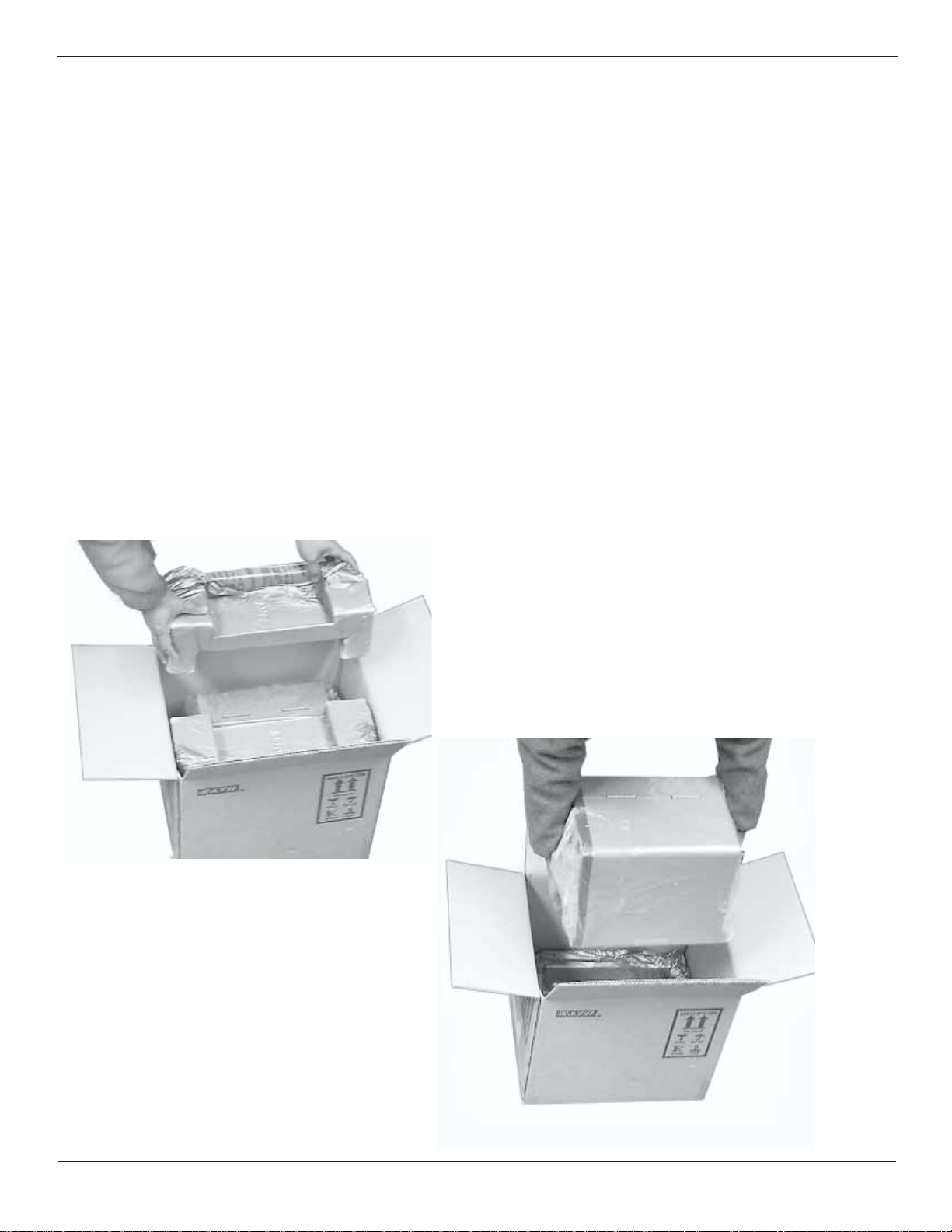
2.2 Unpacking and Parts Identification
Unpack the printer as follows:
Place the box upright on a solid, flat surface.
Open the box and remove any loose items and the first layer of packing
material.
Carefully lift the printer from the box and place it on a solid flat surface.
Inspect the shipping container and printer for any signs of damage that
may have occurred during shipping.
Remove the plastic covering from the printer.
Remove the accessory items from their protective containers.
If the printer has been stored in a cold environment, allow it to reach
room temperature before powering it on.
. NOTE: The following illustrations are representative only. Your printer may not be
packed exactly as shown here, but the unpacking steps are similiar.
REMOVE P ACKING MA TERIAL
LIFT THE PRINTER FROM
THE BOX CAREFULLY
Page 2-2
SATO M-5900RV Operator and Technical Reference Manual
PN 9001081
Rev. C
Page 19

Unpacking and Parts Identification (Cont)
Verify that you have the following items when unpacking:
Printer
Power Cord
Operator's Manual/Programmer and Technical Reference Manual
CD containing Label Wizard SE
Section 2. Installation and Configuration
2.3 Setting Up the M-5900RV
PN 9001081
Rev. C
Consider the following when setting up the printer:
Locate a solid flat surface to set the printer. Make sure there is
enough room at the top and right-hand side (facing the printer) to
provide clearance for the right side access door to swing open.
The location should be near the host computer or terminal. The
maximum distance for RS232 cables is 50 feet and six feet for
Centronics Parallel cables. Cables can be purchased locally, and their
configuration will depend upon the host system being used.
For information on interfacing the printer to a host system, see
Section 5: Interface Specifications.
SATO M-5900RV Operator and Technical Reference Manual
Page 2-3
Page 20

Section 2. Installation and Configuration
2.4 Printer Features
LEFT SIDE
ACCESS P ANEL
OPERATION
PANEL
POTENTIOMETERS
AND DIP SWITCHES
RIGHT SIDE
ACCESS DOOR
PRINT HEAD
AND TEAR BAR
LABEL OUT SLOT
FLIP-DOWN
RIGHT SIDE
ACCESS DOOR
COVER
FANFOLD MEDIA
FEED SLOT
CONNECTIONS
Page 2-4
LEFT SIDE
ACCESS P ANEL
REAR P ANEL
SATO M-5900RV Operator and Technical Reference Manual
PN 9001081
Rev. C
Page 21

Printer Features
PRINT HEAD ASSEMBLY
SHOWN IN OPEN
POSITION
Section 2. Installation and Configuration
LABEL UNWIND ARM
FANFOLD MEDIA
FEED SLOT
LABEL UNWIND
GUIDE
ADJUSTABLE
LABEL EDGE
GUIDE
GREEN PLASTIC LEVER
GUARDS MARKED
"PUSH" "PULL"
PRINT HEAD ASSEMBLY
SHOWN IN CLOSED
POSITION
PN 9001081
Rev. C
SATO M-5900RV Operator and Technical Reference Manual
Page 2-5
Page 22

Section 2. Installation and Configuration
Printer Features
FRAME
PRINT HEAD
FRONT VIEW
TOP HALF
NOTCH/ GAP
SENSOR
REFLECTIVE
EYE-MARK
SENSOR
BOTTOM HALF
NOTCH/ GAP
SENSOR
PLATEN
FRAME
LABEL UNWIND
GUIDE
LABEL UNWIND
ARM
LABEL
TENSION
BAR
SENSORS
HEAD OPEN
SWITCH
Page 2-6
ACCESSORY
COVER
REAR VIEW
ADJUST ABLE LABEL
EDGE GUIDE
SATO M-5900RV Operator and Technical Reference Manual
PN 9001081
Rev. C
Page 23

Section 2. Installation and Configuration
2.5 Operation Panel
The M-5900RV Operation Panel has an LCD screen, user input keys and user
adjustable potentiometers and dip switches, which are located underneath a
flip-down cover on the operation panel.
The power switch is located at the back of the printer.
LCD SCREEN: 2 LINE x 16 Character LCD
display. Used for setting operational
parameters of the printer and displaying error
conditions.
LINE KEY: Momentary switch. Pressing this
key toggles the printer between the on-line
and off-line mode. When the printer is online, it is ready to receive data from the host.
This key acts as a pause during a print job
by taking the printer off-line.
FLIP-DOWN
COVER
FEED KEY: Momentary switch. Pressing
this key feeds one blank label through the
printer when it is off-line. When the printer is
on-line, another copy of the last label will be
printed.
POTENTIOMETERS: Used to fine tune your
printer. Refer to Potentiometer Adjustments,
page 2-40
DSW 2 & 3: Dip switches are used to set operational
parameters of the printer. Refer to Dip Switch Settings,
page 2-13 through 2-18.
NOTE: DSW 1 is located on the RS232S Serial Interface
Card and is used to set transmit/receive parameters. This
card is attached to the main PCB board and can be
removed to access the switches. Refer to Dip Switch
Settings, page 2-13, 2-17 and 2-18.
PN 9001081
Rev. C
SATO M-5900RV Operator and Technical Reference Manual
Page 2-7
Page 24

Section 2. Installation and Configuration
2.6 Rear Panel
FANFOLD MEDIA
FEED SLOT
MODULAR INTERF ACE
BOARD (CENTRONICS
P ARALLEL SHOWN)
MEMORY CARD
OPTION SLOTS
EXTERNAL
CONNECTOR
MEMORY CARD OPTION SLOTS:
PLUG - IN INTERF ACE MODULES
AVAILABLE:
POWER ON/OFF SWITCH:
AC INPUT CONNECTOR:
OFF/ON
SWITCH
AC INPUT
CONNECTOR
Two slots for PCMCIA Memory
Cards (up to 2MB each)
Ethernet, RS232C, RS422/485,
Coax/Twinax or Centronics Parallel
Universal Serial Bus
To turn the printer on or off
Connect to 115V 50/60 Hz.with
cable provided
Page 2-8
EXT. PORT CONNECTOR:
SATO M-5900RV Operator and Technical Reference Manual
External signal connector
PN 9001081
Rev.C
Page 25

Section 2. Installation and Configuration
2.7 Loading Labels or Tags
CAUTION: If your labels are less than the full width of the print head, the outside
edge will eventually wear out a small portion of the print head, resulting in an
area that will not print. Special care must be taken if you plan to use multiple
widths of labels since the damaged portion of the print head caused from edge
wear on a more narrow label may affect the printing on a wider label. We suggest
you plan your print formats carefully to avoid using the area of possible damage
on the print head when using a wider label. The small area of damage will have
no effect on printing with the undamaged part of the print head.
Damage from a label edge is physical damage and is unavoidable. It is not covered
by warranty.
Refer to the following and previous
illustrations while loading your media.
STEP PROCEDURE
1. Raise the printer right side access door. Page. 2-4
2. Open the Print Head Assembly by pulling down forward on the green
Lever Guard atop the assembly. Page. 2-5
3. Slide the green plastic Label Unwind Guide to the outside edge of the
label. If using roll labels (or tags), load the roll onto the Label Unwind
Arm so that the printed side of the label faces upward as it unwinds from
the roll. Page. 2-5, 2-6, 2-10, 2-11, 2-12
4. Push the roll all the way to the inside of the printer, then slide the Label
Unwind Guide against the label roll to hold the roll in place. Page. 2-10
5. If using fanfold labels or tags, set them on a flat surface behind the printer.
Locate the Feed Slot opening at the rear of the printer. Pass the labels
(printed side up) through the slot and over the Label Unwind Arm.
Page. 2-10
6. Slide the adjustable Label Edge Guide to the outside edge of the bracket.
Feed the labels or tags under the Label Tension Bar, through the open Print
Head Assembly and out the front of the printer.
Set the Adjustable Label Edge Guide to keep the labels against the inside
of the printer.
PN 9001081
Rev. C
NOTE: If the Label Dispenser option has been purchased, see Appendix D, for
proper routing instructions. The M-5900RV must be configured for the Label
Dispenser Mode for proper operation. Please refer to DIP Switch Settings
(page 2-15).
SATO M-5900RV Operator and Technical Reference Manual
Page 2-9
Page 26

Section 2. Installation and Configuration
Loading Labels or Tags
STEP PROCEDURE
Continued from previous page
7. Close the Print Head Assembly by pushing down at the front of the plate
atop the assembly (green plastic piece marked "PUSH") until the assembly
clicks into its locked position. Page 2-11
8. Close the right side access door.
LABEL SUPPLY
SPINDLE
FANFOLD FEED SLOT
(COVERS REMOVED
FOR CLARITY)
LABEL
TENSION BAR
PRINT HEAD
SHOWN IN OPEN
POSITION
FANFOLD LABELS - PLACE
ON A FLA T SURFACE
BEHIND PRINTER
FANFOLD FEED
SLOT
LABEL
UNWIND GUIDE
Page 2-10
SATO M-5900RV Operator and Technical Reference Manual
PN 9001081
Rev. C
Page 27

Loading Labels or Tags
Section 2. Installation and Configuration
PRINT HEAD SHOWN
IN OPEN POSITION
LATCH OPEN
PRINT HEAD SHOWN
IN CLOSED POSITION
LATCH CLOSED
PN 9001081
Rev. C
SATO M-5900RV Operator and Technical Reference Manual
Page 2-11
Page 28

Section 2. Installation and Configuration
Loading Labels or Tags
LABEL
TENSION BAR
LABEL
UNWIND GUIDE
LABELS OUT
LABEL UNWIND
ARM
ADJUSTABLE
LABEL EDGE
GUIDE
Page 2-12
SATO M-5900RV Operator and Technical Reference Manual
PN 9001081
Rev. C
Page 29

Section 2. Installation and Configuration
2.8 Dip Switch Settings
Two DIP switches (DSW2 & DSW3) are located underneath a flip-down cover on
the operation panel. These switches can be used to set:
Sensor Type
Head Check Mode
Hex Dump Mode
Receive Buffer Size
Protocol Code
Compatible Mode
DSW2
Print Mode
Pitch Sensor
Backfeed
Print Start Signal
External Signal Type
Repeat Signal
DSW3
A third DIP Switch (DSW1) is located on a RS232 Serial Interface Card and is
used to set transmit/receive parameters. This card is installed by inserting it
through the slot in the back of the printer directly to the main PCB board. The
switches can be set by either removing the card or by opening the left side panel.
DSW1
Each switch is an eight section "toggle" switch. The ON position is always to the
top. To set the switches, first power the unit Off, then position the DIP switches.
Finally after placing the switches in the desired positions, power the printer back
on. The switch settings are read by the printer electronics during the power-up
sequence. They will not become effect until the power is cycled
PN 9001081
Rev. C
SATO M-5900RV Operator and Technical Reference Manual
Page 2-13
Page 30

Section 2. Installation and Configuration
Dip Switch Settings
Printer Setup
Reserved for future use (DSW2-1)
DSW2-1
Reserved
Reserved
ON
OFF
1 2 3 4
DSW2
5 6 7 8
Sensor Type Selection (DSW2-2): Selects between the use of a label gap or a
reflective Eye-Mark. See page 2-6 for the location of these sensors.
DSW2
DSW2-2 SETTING
Off Gap
ON
OFF
On Eye-Mark
1 2 3 4
5 6 7 8
Head Check Selection (DSW2-3): When selected, the printer will check for head
elements that are electrically malfunctioning.
DSW2
DSW2-3 SETTING
Off Disable
ON
OFF
On Enable
1 2 3 4
5 6 7 8
Hex Dump Selection (DSW2-4): Selects Hex Dump mode. (See page 2-38.)
DSW2
DSW2-4 SETTING
Off Disable
ON
OFF
On Enable
1 2 3 4
5 6 7 8
Receive Buffer Selection (DSW2-5): Selects the operating mode of the receive
buffer. See Section 5: Interface Specifications for more information.
DSW2
DSW2-5 SETTING
ON
Page 2-14
Off Single Job
On Multi-Job
SATO M-5900RV Operator and Technical Reference Manual
OFF
1 2 3 4
5 6 7 8
PN 9001081
Rev. C
Page 31

Dip Switch Settings
Printer Setup
Section 2. Installation and Configuration
Reserved for future use (DSW2-6)
DSW2
DSW2-6
Reserved
Reserved
ON
OFF
1 2 3 4
5 6 7 8
Protocol Code Selection (DSW2-7): Selects the command codes used for
protocol control. Refer to Appendix E for more information.
DSW2
DSW2-7 SETTING
Off Standard
ON
OFF
On Non-Std.
1 2 3 4
5 6 7 8
Emulation Mode (DSW2-8): For emulating features of the original M-5900
software.
DSW2
DSW2-8 SETTING
ON
Off Normal
Operation
OFF
PN 9001081
Rev. C
On Orig.M-5900
1 2 3 4
5 6 7 8
Mode Selection (DSW3-1 and DSW3-2): Selects the operating mode of the
printer. Batch/Continuous disables the label taken (Dispense option) sensor.
DSW3
DSW3-1 DSW3-2 SETTING
Off Off Batch/Continuous
Off On Tear Off
ON
OFF
1 2 3 4
5 6 7 8
On Off Cutter
On Off Dispenser
SATO M-5900RV Operator and Technical Reference Manual
Page 2-15
Page 32

Section 2. Installation and Configuration
Dip Switch Settings
Printer Setup
Label Sensor Selection (DSW3-3): Enables or disables the Label Pitch sensor. If
the sensor is enabled, it will detect the edge of the label and position it automatically.
If it is disabled, the positioning must be under software control using Line Feed
commands for continuous media printing.
DSW3
DSW3-3 SETTING
Off Enable
ON
OFF
On Disable
1 2 3 4
5 6 7 8
Back-Feed Selection (DSW3-4): When Back-Feed is enabled, the printer will
position the label for dispensing/cutting and retract it before printing the next label.
See page 2-40 for information on setting the amount of offset.
DSW3
DSW3-4 SETTING
Off Enable
ON
OFF
On Disable
1 2 3 4
5 6 7 8
External Signal Interface
The EXT connector on the printer rear panel is intended for use with the external
printer accessories such as label rewinders or applicators. The 14-pin Centronics
type connector provides a choice of four different output signals along with various
error conditions.
DSW3-5 SETTING
Off Disabled
On Enabled
Note: This switch must be in the On position if an external device is used to control the
printer via the EXT connector.
Page 2-16
EXT Print Start Signal Selection (DSW3-5): Allows an external device to
initiate a label print. See page 5-12 for a description of signal requirements.
DSW3
ON
OFF
1 2 3 4
SATO M-5900RV Operator and Technical Reference Manual
5 6 7 8
PN 9001081
Rev. C
Page 33

Section 2. Installation and Configuration
Dip Switch Settings
Printer Setup
External Signal Type Selection (DSW3-6 and DSW3-7): Selects the type of
output signal. See page 5-13 for a description of signal types.
DSW3-6 DSW3-7 SETTING
DSW3
ON
Off O ff Type 4
OFF
Off O n Type 3
On Off Type 2
1 2 3 4
5 6 7 8
On O n Type 1
Repeat Print via External Sign (DSW3-8): Allows an external device to control
the reprint of the label in the print buffer. See page 5-12 for a description of the
signal requirements.
DSW3
DSW3-8 SETTING
Off Disabled
ON
OFF
On Enabled
1 2 3 4
5 6 7 8
RS232 Transmit/Receive Setting
(Located on RS232S Serial Interface Card)
Data Bit Selection (DSW1-1): This switch set the printer to receive either 7 or
8 bit data bits for each byte transmitted.
DSW1
DSW1-1 SETTING
Off 8 data bits
On 7 data bits
Parity Selection (DSW1-2 and DSW1-3): Selects the type of parity used for
error detection.
DSW1-2 DSW1-3 SETTING
Off Off No Parity
Off On Even
On Off Odd
ON
OFF
ON
OFF
1 2 3 4
DSW1
1 2 3 4
5 6 7 8
5 6 7 8
PN 9001081
Rev. C
On On Not Used
SATO M-5900RV Operator and Technical Reference Manual
Page 2-17
Page 34

Section 2. Installation and Configuration
Dip Switch Settings
RS232 Transmit/Receive Setting
Stop Bit Selection (DSW1-4): Selects the number of stop bits to end each byte
transmission.
DSW1
DSW1-4 SETTING
Off 1 Stop Bit
On 2 Stop Bits
Baud Rate Selection (DSW1-5 and DSW1-6): Selects the data rate (bps) for
the RS232 port.
ON
OFF
1 2 3 4
5 6 7 8
DSW1-5 DSW1-6 SETTING
Off Off 9600
ON
DSW1
OFF
Off On 19200
On Off 4800
1 2 3 4
5 6 7 8
On On 2400
Protocol Selection (DSW1-7 and DSW1-8): Selects the flow control and status
reporting protocols. See Section 5: Interface Specifications for more information.
DSW1-7 DSW1-8 SETTING
Off Off Rdy/Bsy
ON
DSW1
OFF
Off On Xon/Xoff
On Off Bi-Com
1 2 3 4
5 6 7 8
On On Status 2
Page 2-18
SATO M-5900RV Operator and Technical Reference Manual
PN 9001081
Rev. C
Page 35

Section 2. Installation and Configuration
2.9 Default Settings
Switch Selections
All switches are placed in the Off position (default) for shipping. This will result in the
following operating configuration:
Communications:
Protocol:
Sensor: Gap Sensor
Receive Buffer: Single Job
Mode: Batch Continuous
Label Sensor: Sensor Used
Backfeed: Disabled
External Signals: Disabled
(1) Active only if an RS232 Interface Card is installed in the printer.
Software Default Settings - The printer stores any software settings upon receipt
from the host and uses them until they are again changed by receipt of a command
containing a new setting. These settings are stored in non-volatile RAM and are not
affected by powering the printer off. The printer may be reset to use the default
software settings by depressing the LINE and FEED keys simultaneously while
powering the printer on. This will result in the following default configuration:
(1)
(1)
8 data bits, no parity, 1 Stop bit, 9600 Baud
Ready/Busy
retemaraPsgnitteStluafeD
ssenkraDtnirP"3"
deepStnirP.cesrep.ni3
ecnerefeRtnirP1000=latnoziroH,1000=lacitreV
oreZhsalS
eniL-nOotuAdelbanE
Once the default operation is completed, a DEFAULT SETTING COMPLETED
message will be displayed on the LCD panel and a single "beep" will be heard. The
printer should be powered off while this message is being displayed. This saves the
default settings in the EEPROM where they will be automatically loaded the next time
the printer is powered on.
DEFAULT SETTING
COMPLETED
PN 9001081
Rev. C
SATO M-5900RV Operator and Technical Reference Manual
Page 2-19
Page 36

Section 2. Installation and Configuration
2.10 Printer Adjustments
The LCD Panel on the M-5900RV is used in conjunction with the LINE and FEED switches by
the operator to manually enter printer configuration settings. Many of the settings can also be
controlled via software commands and in the case of conflict between software and control
panel settings, the printer will always use the last valid setting. If you load a label job that
includes software settings and then enter a new setting via the Operation Panel, the manually set
values will be used by the printer. If you set the values manually and then download a job with
software settings, the software settings will be used.
POWER ON
Normal/User Mode
POWER
User Test Print
FEED+POWER
Advanced Mode
LINE+POWER
Load SATO Default Settings
LINE+FEED+POWER
User Download Defined Protocol Codes
DSW2-7=ON +LINE+POWER
Reset to SATO Default Protocol Codes
DSW2-7=ON +LINE+FEED+POWER
ONLINE
QTY:000000
USER TEST PRINT
SMALL LARGE
ADVANCED MODE
SETUP
DEFAULT SETTING
COMPLETED
USER DOWNLOAD
ALT. PROTOCOL
DEFAULT COMPLETED
Page 2-21
Page 2-36
Page 2-24
Page 2-19
Page E-2
Page E-2
Page 2-20
Emulation Mode
DSW2-8=ON+POWER
Print Hex Dump Label
POWER
Print Hex Dump Label
DSW2-4=ON+POWER
SATO M-5900RV Operator and Technical Reference Manual
ONLINE
QTY:000000
PRINT BUFFER
Hex Dump Label
RECEIVE BUFFER
Hex Dump Label
Page 2-15
Page 2-38
Page 2-38
PN 9001081
Rev. C
Page 37

Section 2. Installation and Configuration
Printer Adjustments
Normal Mode
When the printer is powered on, the readout should display the following message:
ONLINE
QTY: 000000
The LCD Panel will display the Online status on the top line of the display. The bottom line will
contain the label quantity (QTY) status. The On Line message will be changed to OFF LINE
whenever the printer is switched offline by depressing the LINE key. As soon as a print job is
received, the QTY message will indicate the number of labels to be printed. As soon as the label
job begins to print, the display will indicate the number of labels remaining in the print job that
remain to be printed.
User Mode
To enter the USER mode, perform the following steps:
STEP PROCEDURE
1. The printer is first taken offline by pressing the LINE key once.
The display will change to OFFLINE.
OFFLINE
000000
2. Press the FEED and LINE keys simultaneously for more than one
second. The printer now displays the first USER mode
adjustment (Print Darkness).
Print Darkness Setting
There are five Darkness (or heat range) settings on the printer. The higher
numbers represent darker settings. The current setting is indicated by a line under
one of the range settings.
To change the setting perform the following steps:
STEP PROCEDURE
1. Use the LINE key to step the underlined cursor to the desired
setting.
1 = Light
2 = Slightly Light
3 = Medium
4 = Slightly Dark
5 = Dark
2. Once the correct setting is underlined, press the FEED key to
accept the setting and advance to the next adjustment.
PRINT DARKNESS
12 345
PN 9001081
Rev. C
Note: The setting can be overridden by software. Finer adjustments can also be made
using the PRINT potentiometer setting on the adjustment panel.
SATO M-5900RV Operator and Technical Reference Manual
Page 2-21
Page 38

Section 2. Installation and Configuration
Printer Adjustments
Print Speed Adjustment
There are four Speed settings on the printer. The setting is listed on the bottom
line of the display. The current setting is indicated by an underline under one of
the speed settings. To change the setting:
STEP PROCEDURE
1. Use the LINE key to step the underlined cursor to the desired
speed setting.
2 = 2 in/s (50mm/s)
3 = 3 in/s (75mm/s)
4 = 4 in/s (100mm/s)
5 = 5 in/s (125mm/s)
2. Once the correct setting is underlined, press the FEED key to
accept the setting and advance to the next adjustment.
Note: The setting can be overridden by software.
PRINT speed
2 345
Pitch Offset and Direction
The label pitch is the distance from the leading edge, (the edge that comes out of
the printer first) of a label and the leading edge of the printing. The leading edge
position of the label can be adjusted relative to the print head +/- 49 mm in
increments of 1 mm using the following procedure. Once the position is set, it can
be adjusted +/- 3.75 mm using the PITCH potentiometer on the adjustment panel,
(see page 2-40).
LABEL FEED
DIRECTION
Page 2-22
MOVED WITH MINUS
(-) OFFSET
ORIGINAL PRINT LINE
MOVED WITH POSITIVE
(+) OFFSET
SATO M-5900RV Operator and Technical Reference Manual
PN 9001081
Rev. C
Page 39

Section 2. Installation and Configuration
Printer Adjustments
Pitch Offset and Direction
To change the setting perform the following steps:
STEP PROCEDURE
1. Use the LINE key to step the underlined cursor to either the positive
(+) or the negative (-) selection. A positive selection increases the
pitch offset direction while a negative selection decreases the pitch
offset direction.
2. Once the desired setting is underlined, press the FEED key to accept
the (+/-) setting and advance to the first numerical position. Press the
LINE key to set a value in the first position (0-4 only). Each time the
line key is pressed, it will increment one step. Press the FEED key to
advance to the second position to set a value. Press the line key
repeatedly to advance to the desired value (0-9). Once the setting is
correct, press the FEED key to accept the setting and advance to the
Cancel Print job display.
3. You may wish to check your settings by printing a test label after you
have completed the adjustments to ensure that they are correct. See
page 2-36 for instructions on how to print a test label.
PN 9001081
Rev. C
SATO M-5900RV Operator and Technical Reference Manual
Page 2-23
Page 40

Section 2. Installation and Configuration
Printer Adjustments
Cancel Print Job
If the printer has a print job(s) loaded in memory, selecting YES will cause the
job(s) to be cleared. The default selection is NO. Make sure that you want to
cancel the print job before selecting YES as the job cannot be recovered and will
have to be retransmitted to the printer.
To cancel the print, perform the following steps:
cancel print job
noyes
STEP PROCEDURE
1. Use the LINE key to step the underlined cursor to either
No or Yes.
2. Once the correct setting is underlined, press the FEED key to accept
the setting and terminate the user mode of operation and return to
the normal mode OFFLINE display.
If you wish to change any of the settings, you must enter the user
mode again by simultaneously pressing FEED and LINE keys for
more than one second.
2.11 Advanced Mode Settings and Adjustments
Advanced mode is provided to make adjustments that require only occasional
adjustments. Since they affect the basic operation of the printer, the procedure for
entering this mode is designed to prevent someone from accidentally changing the
settings.
To Enter Advanced Mode:
Power on the printer while pressing the LINE key. The printer will emit an audible
signal and display Advanced Mode Setup on the LCD panel.
advanced mode
setup
From the advanced mode display, the advanced settings are accessed in sequence
by pressing the FEED key.
Page 2-24
SATO M-5900RV Operator and Technical Reference Manual
PN 9001081
Rev.C
Page 41

Advanced Mode
Section 2. Installation and Configuration
advanced mode
setup
FEED KEY
zero slash
yes no
auto online
yes no
vert. offset
v: 1051
FEED KEY
calendar enabled
No yes
calendar enabled
25/25/25 25:25
ignore cr/lf
yes no
print darkness
type 1
Hor. offset
h: +/-0001
gap [0.1v]
input [1.6v]
FEED KEY
exit adv. mode
no yes
advanced mode
setup
Press FEED Key to recycle back through the
ADVANCED MODE SETUP Section or press
the LINE key to select the Counters Section.
For the Counters Section refer to Page 2-35
Refer to the pages 2-26 through 2-36 for
details of each setting
offline
000000
PN 9001081
Rev. C
SATO M-5900RV Operator and Technical Reference Manual
Page 2-25
Page 42

Section 2. Installation and Configuration
Advanced Mode
Zero Slash Setting
advanced mode
setup
This setting determines if a zero is printed with a slash or without a slash. This setting can
also be controlled via software commands. When YES is selected, the U, S, M, WB, WL,
XU, XS, XM, XB, XL and vector fonts will have a slash through the center of the zero
character.
To access this setting, perform the following steps:
STEP PROCEDURE
1. From the Advanced Mode Setup, press the FEED key to move to the
Zero Slash display.
2. Use the LINE key to step the underlined cursor to either YES or NO.
3. Once the correct setting is underlined, press the FEED key to accept
the setting and advance to the Auto Online display.
Feed
Key
zero slash
yes no
Auto Online Setting
This setting determines the mode in which the printer powers up. If the YES selection is
made, the printer powers up in the ONLINE mode and is ready to print. If NO is
selected, the printer powers up in the OFFLINE mode and must be manually placed in
the ONLINE mode by pressing the LINE key before it is ready to print.
To access this setting perform the following steps:
STEP PROCEDURE
1. Use the LINE key to step the underlined cursor to either YES or
NO.
auto online
yes no
2. Once the correct setting is underlined, press the FEED key to
accept the setting and advance to the Vertical Offset display.
Page 2-26
SATO M-5900RV Operator and Technical Reference Manual
PN 9001081
Rev. C
Page 43

Section 2. Installation and Configuration
Advanced Mode
Vertical Of fset Setting
Vertical Offset is the distance down from the leading edge, (the edge of the label
that comes out of the printer first) to the first vertical print position. It is always a
positive setting since making it negative would move it up and off the printable
label. This setting changes the base reference point for all subsequent label jobs.
Its effect is identical to the
printer moves the label in discrete steps equal to the size of the print dot, the units
of measure for Vertical Offset distance is dots. The maximum value that can be set
is 1424 (2848 in Expanded mode).
Each dot is .0049 inches (.125mm)
Note: This setting can be overridden by the Base Reference Point Command. It is
recommended that you relocate printing in your software as adjustments made here
will affect all of you label formats.
To access this setting perform the following steps:
STEP PROCEDURE
<ESC><ESC>
<ESC> A3 Base Reference point command. Since the
<ESC><ESC>
1. Use the LINE key to step to the desired setting. The display will
increment one step each time the LINE key is pressed. Press the
FEED key to advance to each subsequent digit.
vert. offset
v: 0000
2. Once the setting is correct, press the FEED key to accept the
setting and advance the display to the Horizontal Direction display.
ORIGINAL PRINT
LINE LOCA TION
PRINT LINE
VERTICALLY
RELOCA TED USING
THE LINE KEY IN
LABEL FEED
DIRECTION
STEP 1
PN 9001081
Rev. C
SATO M-5900RV Operator and Technical Reference Manual
Page 2-27
Page 44

Section 2. Installation and Configuration
Advanced Mode
Horizontal Offset and Direction Setting
Horizontal Offset is the distance that the label image is shifted either to the right or left
on the label. The image is shifted to the left (towards the inside edge of the label) for a
positive setting and is shifted to the right (towards the outside edge of the label) for a
negative setting. This setting changes the base reference point for all subsequent label
jobs. Its effect is identical to the
printer can only print in discrete steps equal to the size of the print dot, the units of
measure for the Horizontal Offset distance is dots.
Note: This setting can be overridden by the Base Reference Point Command. It is
recommended that you relocate printing in your software as adjustments made here will
affect all of your label formats.
To access this setting perform the following steps:
STEP PROCEDURE
1. Use the LINE key to step the underline to either the positive (+) or
negative (-) selection. A positive selection increases (moves) the
horizontal reference point for the label to the right edge of the label,
towards the outside, while a negative selection moves the horizontal
reference point for the label to the left, towards the inside of the printer.
<ESC><ESC>
<ESC> A3 Base Reference point command. Since the
<ESC><ESC>
hor. offset
h:+0000
2. Once the setting is underlined, press the FEED key to accept the setting
and advance the display to the Horizontal Offset adjustment.
3. Use the LINE key to step the counter to the desired setting. The display
will increment one step each time the LINE key is pressed. Press the
FEED key to advance to each subsequent digit. The horizontal direction
set in the previous step will be displayed in front of the Offset setting.
4. Once the setting is correct, press the FEED key to accept the setting
and advance to the Sensor Threshold display.
Page 2-28
SATO M-5900RV Operator and Technical Reference Manual
PN 9001081
Rev. C
Page 45

Advanced Mode
Printable Area
Section 2. Installation and Configuration
For Sensor locations, see page 2-6
14 mm
Eye-Mark Sensor
Feed Direction
1.5 mm
.06 in.
4.4"
Max.
Eye-Mark
1.5 mm
.06 in.
LABEL
1.5 mm
.06 in.
3 mm
.12 in.
1.5 mm
.06 in.
3 mm
.12 in.
Feed
Direction
Gap
Feed
Direction
1.5 mm
.06 in.
1.5 mm
.06 in.
4.4"
Max.
4.4"
Max.
LABEL
1.5 mm
.06 in.
LABEL
1.5 mm
.06 in.
3 mm
.12 in.
1.5 mm
.06 in.
PN 9001081
Rev. C
Tag
SATO M-5900RV Operator and Technical Reference Manual
Page 2-29
Page 46

Section 2. Installation and Configuration
Advanced Mode
Sensor Threshold Level
The M-5900RV printer determines the location of the leading edge of the label by
measuring the difference between light levels when it sees either a label edge or a black
Eye-Mark. This adjustment allows you to manually set the threshold voltage level
between the maximum and minimum light levels. DIP switch DSW2-2 selects the sensor
type. If DSW2-2 is in the OFF position, the setting will be for a See-Thru (or Gap)
sensor and the LCD will display GAP on the top line along with the current setting. If
DSW2-2 is in the ON position, the LCD will display Eye on the top line with its
current setting. If the value entered for the bottom line setting is 0.0V, then the
printer will automatically calculate the setting when the first label is fed after the printer
is powered on or the head is closed. There are some instances where the automatically
calculated value must be adjusted to ensure reliable label feeding, such as when the
backing opacity or the reflectance of the Eye-Mark varies significantly within a roll of
labels or between label rolls. In these instances the value should be set using the
following procedures.
gap [x.xv]
input [x.xv]
GAP SENSOR: When setting the gap threshold, the voltage shown on the top
line of the display must be measured with nothing but the backing paper in the
sensor and then again with a label still attached to the backing. The formula to
be used for setting the threshold is:
(High Voltage Level + Low Voltage Level) x 0.5 = Input Value
Perform the steps on the following page:
Page 2-30
SATO M-5900RV Operator and Technical Reference Manual
PN 9001081
Rev. C
Page 47

Section 2. Installation and Configuration
Advanced Mode
GAP SENSOR:
Perform these steps:
STEP PROCEDURE
1. Insert a label still attached to the backing into the sensor and close the
head. Record the voltage shown on the top line of the LCD panel.
This line should have the message "GAP" on the top line (DIP switch
DSW2-2 = OFF). Make sure the label is all the way under the sensor
and the See through Sensor is aligned over your label.
2. Stip the label from the backing and insert the backing strip under the
sensor and close the head. Record the voltage shown on the top line
of the LCD panel. The voltage ranges measured should be within the
following ranges:
Backing with Label Label Backing Only
2.0V to 3.5V 1.0V or less
If the measured values are outside this range, you may have trouble
finding a value that will work properly under all conditions. If this is
the case, a higher quality label may be needed to get adequate
performance.
3. Calculate the input point voltage using the formula shown on page 30.
4. Use the LINE key to step the counter to the desired value. The display
will increment one step for each time the LINE key is pressed. If the
LINE key is held down for more than two seconds, it will
automatically go into the fast scroll mode. The reading will advance
to a setting of 4.9 (the maximum voltage) after which it will
automatically wrap and start at 0.0" again. If a value of 0.0" is set, the
printer will automatically set the level half way between the two
measured voltages each time the printer is powered on with labels
loaded.
5. Repeat this procedure using values slightly higher of lower until the
optimum performance is obtained. If you cannot find a setting
between the high and low readings that gives adequate performance,
then the label stock has too much variation in its opacity and a better
quality stock should be used.
PN 9001081
Rev. C
6. Once the setting is correct, press the FEED key to accept the setting.
SATO M-5900RV Operator and Technical Reference Manual
Page 2-31
Page 48

Section 2. Installation and Configuration
Advanced Mode
Sensor Threshold Level (Cont)
"Eye-Mark" (Reflective) Sensor: When setting the "Eye-Mark" threshold, the
voltage must be measured with nothing but the label over the sensor and then again
with the printed "Eye-Mark" over the sensor. The formula for this is:
(High Voltage Level + Low Voltage Level) x 0.5 = Input Value
To access this setting, perform the following steps:
STEP PROCEDURE
1. Insert a label into the sensor and close the Label Hold-Down. Make
sure the printed Eye is not over the sensor. Record the voltage
shown on the top line of the LCD panel. This line should have the
message Eye on the top line (DIP switch DSW2-2 =ON).
2. Now pull the label forward until the Eye-mark" is positioned over the
sensor (the voltage reading should be at its highest point). Record the
voltage shown on the top line of the LCD panel. The voltage ranges
measured should be within the following ranges:
Label Only Eye Mark
1.0V or less 2.5V to 3.5V
If the measured values are outside this range, you may have trouble
finding a value that will work properly under all conditions. If this is
the case, a higher quality label may be needed to get adequate
performance.
3. Calculate the input point voltage using the formula shown at the
beginning of this page.
4. Use the LINE key to step the counter to the desired setting. The
display will increment one step for each time the LINE key is pressed.
If the LINE key is held down for more than two seconds, it will
automatically go into the fast scroll mode. The reading will advance to
a setting of 4.9 (the maximum voltage) after which it will automatically
wrap and start at 0.0 again. If a value of 0.0" is set, the printer will
automatically set the level each time the printer is powered on with
labels loaded or the head is closed.
5. Repeat this procedure using values slightly higher or lower until the
optimum performance is obtained. If you cannot find a setting that will
give you adequate performance, then the label stock or printed "EyeMark" too much variation in its reflectance and a better quality stock
should be used.
6. Once the setting is correct, press the FEED key to accept the setting
and advance to the Calendar Set display.
Page 2-32
SATO M-5900RV Operator and Technical Reference Manual
PN 9001081
Rev. C
Page 49

Advanced Mode
Calendar Set
Section 2. Installation and Configuration
calendar enabled
no yes
STEP PROCEDURE
1. Year: The first display shown will have the two digit year selection
underlinded. Press the LINE key to scroll through the dates. The year
number will increase by one value each time the LINE key is pressed.
2. Month: After you have set the correct year, press the FEED key to
advance the underline cursor to the two digit Month position. Press
the LINE key to scroll through the numbers corresponding to the
month. The month number will increase by one value each time the
LINE key is pressed.
3. Day: After you have set the correct month, press the FEED key to
advance the underline cursor to the two digit Day position. Press the
LINE key to scroll through the numbers corresponding to the date.
The date number will increazse by one value each time the LINE key
is pressed.
4. Hour: After you have set the correct date, press the FEED key to
advance the underline cursor to the two digit Hour position. Press the
LINE key to scroll through the numbers corresponding to the hour
(using a 24 hour clock). The hour number will increase by one value
each time the LINE key is pressed.
Feed
Key
Calendar
00/00/00 00:00
PN 9001081
Rev.C
5. Minute: After you have set the correct hour, press the FEED key to
advance the underline cursor to the two digit minute position. Press
the LINE key to scroll through the numbers corresponding to the
minute. The minute number will increase by one value each time the
LINE key is pressed.
6. After you have set the calendar, press the FEED key to accept the
setting and advance to the next display.
SATO M-5900RV Operator and Technical Reference Manual
Page 2-33
Page 50

Section 2. Installation and Configuration
Advanced Mode
Ignore Carriage Return/Line Feed
This setting is an entry provided to ignore a Carriage Return or Line Feed
command in the data stream.
STEP PROCEDURE
1. Use the LINE key to step the underline cursor to the desired setting.
ignore cr/lf
yes no
2. Once the desired setting is underlined, press the FEED key to
accept the setting and advance to the next adjustment.
Print Darkness Setting
There are two Darkness (or heat range) settings. If you are printing large amounts of
coverage on each label you will want to choose TYPE 2 to prevent head saturation or
excessive heat buildup. The current setting is indicated by a line under one of the range
settings. Refer to Page 2-40 for user mode darkness settings that work in conjunction with
these two broad range settings.
STEP PROCEDURE
1. Use the LINE key to step the underline cursor to the desired setting.
print darkness
type 1
2. Once the desired setting is underlined, press the FEED key to
accept the setting and advance to the next adjustment.
Exit Advanced Mode
To access this setting, perform the following steps:
STEP PROCEDURE
1. Use the LINE key to step the underline cursor to either NO or Yes.
2. Once the desired setting is underlined, press the FEED key to
accept the setting and advance to the next adjustment. If you selected Yes
the display will advance to OFFLINE. If you selected NO you will continue
in the Advanced Mode for access to the Advanced Mode Counters.
Once the desired setting is underlined, press the FEED key.
exit adv. mode
Page 2-34
no yes
Feed Key
advanced mode
setup
SATO M-5900RV Operator and Technical Reference Manual
offline
000000
PN 9001081
Rev. C
Page 51

Section 2. Installation and Configuration
Advanced Mode
Advanced Mode Counters
The Advance Mode Counters is provided for reading and clearing internal counters. These
counters allow the user to keep track of the number of centimeters of label material that has
passed through the printer, how many labels have been dispensed or how many labels have been
cut. The Advanced Mode Counters display is entered by pressing the LINE key from the
Advanced Mode Setup; then press the FEED key to advance through the counters.
advanced mode
setup
The Couters display allows you to select the counter to be viewed or cleared.
STEP PROCEDURE
1. Press the FEED key to advance through the Counters display.
Line
Key
advanced mode
counters
counters
hd dsp cut life
HD: Head Counter
DSP: Dispense Counter
CUT: Cutter Counter
LIFE: Life Counter
2. Use the LINE key to step the underline cursor to the counter to be
reset or displayed; the Head counter (HD), Dispenser (DSP)
counter, CUT (Cutter) counter, or the LIFE counter.
PN 9001081
Rev. C
3. Once the desired setting is underlined, press the FEED key to
display the values stored for that particular counter.
head counter
cut counter
0.0
0.0
life counter
SATO M-5900RV Operator and Technical Reference Manual
0.0
Page 2-35
Page 52

Section 2. Installation and Configuration
Page 2-36
SATO M-5900RV Operator and Technical Reference Manual
PN 9001081
Rev. C
Page 53

Section 2. Installation and Configuration
Printing Test Labels
Print Size
STEP PROCEDURE
3. If SMALL is underlined, the Print Size message will be displayed. You
must enter the size of the label. The minimum label size that can be
selected is 4 cm (1.6) and the maximum size is 10 cm (3.9). Press
the FEED key and then press the LINE key to increment the setting by
1 cm each time the key is pressed. Once the maximum size is reached,
the display will wrap around and start incrementing at 4 cm again.
Once the correct label width is selected, press the FEED key to initiate
the print.
4. If you wish to pause the printer after it starts to print a test label,
press the FEED key. Press the FEED key again to resume the test
label printing. To stop the test label print, pause the printer and
then turn power off.
PN 9001081
Rev. C
LARGE LABEL
SATO M-5900RV Operator and Technical Reference Manual
SMALL LABEL
Page 2-37
Page 54

Section 2. Installation and Configuration
2-13 Hex Dump Diagnostic Labels
In addition to the Printing Test Labels, the printer contents of the receive and print
buffers can be examined using the Hex Dump Test Labels.
Print Buffer Hex Dump
The contents of the Print Buffer can be examined using the Hex Dump mode. The
label numbers each line of data received in the left-hand column, the data in hexadecimal
format in the center columns followed by the same data in ASCII format in the
right-hand column.
STEP PROCEDURE
1. Turn the printer ON.
2. Create and print a label.
3. Place the printer in the Off-Line mode by pressing the LINE key.
4. Place DSW2-4 in the ON position.
5. Press the LINE key to place the printer back in the On-Line status.
6. Press the FEED key.
7. A label should be printed containing the contents of the print buffer
in hexadecimal format.
8. Return DSW2-4 to the OFF position.
9. Turn the printer OFF and then back ON to place it back in the
normal print mode.
Receive Buffer Hex Dump
The data that is being received by the printer (before it is placed in the Print Buffer) can
be examined by using the Hex Dump Mode. The label numbers each line of data
received in the left-hand column, the data in hexadecimal format in the center columns
followed by the same data in ASCII format in the right-hand column.
STEP PROCEDURE
1. Turn the printer OFF.
2. Place DSW2-4 in the ON position.
3. Turn the printer ON.
4. Transmit the data to the printer.
5. The data received is printed out on a label in hexadecimal format.
6. Return DSW2-4 to the OFF position.
7. Turn the printer OFF and then back ON to place it back in the normal
print mode.
Page 2-38
SATO M-5900RV Operator and Technical Reference Manual
PN 9001081
Rev. C
Page 55

Hex Dump Diagnostic Labels
LINE
NUMBERS
DATA IN HEXADECIMAL
PRINT BUFFER HEX LABEL
Section 2. Installation and Configuration
DATA IN ASCII
FORMAT
FORMAT
PN 9001081
Rev. C
RECEIVE BUFFER HEX LABEL
SATO M-5900RV Operator and Technical Reference Manual
Page 2-39
Page 56

Section 2. Installation and Configuration
2.14 Potentiometer Adjustments
Three potentiometers are located underneath a snap-on cover on the front panel.
These are used to fine tune your printer as follows:
Print Potentiometer to adjust print darkness/lightness of your print output.
Offset Potentiometer to adjust amount of back/forward feed for
dispenser/cutter/tear-off bar position (+/- 3.75 mm).
Pitch Potentiometer to adjust home position of the label (+/- 3.75 mm).
Affects stop position of label feed, print position and dispense
position.
OFFSET
PRINT
PITCH
Print
This potentiometer is used to adjust the darkness/lightness of your printer output.
Slowly turn the potentiometer counterclock wise to lighten or clockwise to darken.
Offset
When the printer is in the dispenser mode, (dip switch setting, page 2-15) the Feed
Offset is used to correctly position the label for dispensing/cutting. Once the correct
Feed Offset is obtained, the printer will position the label for dispensing/cutting and
then reposition the next label before printing.
The amount of backfeed is controlled by the OFFSET potentiometer on the front
panel. When turned all the way clockwise, the amount of backfeed adjustment is
+3.75 mm and -3.75 mm when it is turned all the way counterclockwise.
STEP PROCEDURE
1. Turn the printer on.
2. Press the LINE key to place the printer Off line.
3. Press the FEED key to feed out a blank label.
4. Adjust the position using the OFFSET potentiometer on the front
control panel and feed another label by depressing the FEED key.
5. When the adjustment is correct, turn the printer off.
Page 2-40
SATO M-5900RV Operator and Technical Reference Manual
PN 9001081
Rev. C
Page 57

Section 2. Installation and Configuration
Potentiometer Adjustments
Pitch
After the pitch has been set, it is sometimes desirable to make minor adjustments. This
can be done using the PITCH potentiometer ont the front panel. This potentiometer
is set at the factory so that it has a range of +/- 3.75 mm. The midpoint setting should
have no effect on the pitch. Turning the potentiometer all the way clockwise should
move the print position 3.75 mm up towards the top edge of the label. Turning it all
the way counterclockwise should move the print position down 3.75 mm.
STEP PROCEDURE
1. While depressing the FEED key on the front panel turn the printer on.
2. Refer to Page 2-36, "Printing Test Labels" and print a label, large or
small.
3. Adjust the PITCH potentiometer on the front panel until the first print
position is at the desired location on the label. If the potentiometer
does not have enough range, then you will must change the pitch
setting using the front panel display.
4. Press the FEED key to stop the printer.
Adjusting the PITCH potentiometer will affect the stop position of the
label and the cut/dispense/tear-off postition.
Label Feed
Direction
ABCDEFGH
ABCDEFGH
ABCDEFGH
Moved with
Minus (-) Pitch
Potentiometer
Original Position on
Label
Moved with
Positive (+) Pitch
Potentiometer
PN 9001081
Rev. C
SATO M-5900RV Operator and Technical Reference Manual
Page 2-41
Page 58

Section 2. Installation and Configuration
®
Page 2-42
SATO M-5900RV Operator and Technical Reference Manual
PN 9001081
Rev. C
Page 59

Section
Adjustments and Maintenance
3.1 Introduction
The following information is presented in this section:
Adjusting the Print Quality
Cleaning the Print Head and Platen
Replacing the Print Head
3.2 Adjusting the Print Quality
The M-5900RV printer is equipped with two different methods of adjusting the
quality of the print; print darkness and speed. When adjusting the printer for
optimum print quality, a bar code verifier system should be used. The human eye
is a poor judge of the relative widths of the bars in a symbol, a characteristic that
is extremely important for good bar code quality.
!
Darkness (Print)
This adjustment allows the user to control (within a specified range), the amount
of power that is used to activate the individual print head elements. It is
important to find a proper print darkness level based on your particular label and
ribbon combination. The printed images should not be too light nor should the
ink from the ribbon "bleed". The edges of each image should be crisp and will
defined.
You can select a value from the Print Darkness range by using the front LCD panel
or by downloading a setting using the Print Darkness software command. If you
use the LCD panel there are five Darkness (or heat range) settings. See page 2-21
for method.
If you use the Print Darkness software command you can input a precise value of
1 to 5. See page 4-58, Programming Reference for method.
Once the value has been selected, the PRINT Potentiometer on the front panel
can be used to make finer adjustments. See next page for method.
PN 9001081
Rev. C
SATO M-5900RV Operator and Technical Reference Manual Page 3-1
Page 60

Section 3. Adjustments and Maintenance
Print Potentiometer
If necessary, use the PRINT potentiometer on the operator panel to make
fine adjustments for print darkness. It provides a continuous range of
adjustment, allowing you to make precise changes. Use a small cross-point
screwdriver, turning clockwise for darker prints and counterclockwise for
lighter prints.
NOTE: The PRINT potentiometer
adjustment will affect the darkness in
all of the command code speed
ranges, i.e., if the PRINT
potentiometer is adjusted for lighter
prints, the darkness will be lighter in
all speed ranges selected by the
command code.
Print Speed
The other method of controlling print quality is by controlling the speed at which
the label is printed. This adjustment is made only on an individual label basis
using either the Print Speed command code or the LCD display panel. For more
details on this command, see Page 4-64 in Section 4: Programming Reference.
Changing the print speed allows the user to control the amount of time allowed
for print element cooling before the media is stepped to the next print position.
It is especially critical when printing "ladder" bar codes (bar codes printed with
the bars parallel to the print line). When printing a "ladder" bar code, it is
important to allow the head to cool sufficiently before stepping to the next
position. If it does not have sufficient time to cool, the bar will be "smeared" on
the trailing edge.
You can select a value from the Print Speed adjustment range by using the front
LCD panel or by downloading a setting using the Print Speed software command.
If you use the LCD panel there are four settings. See page 2-22 for method.
If you use the Print Speed software command you can input a precise value of 1
to 5. See page 4-64, Programming Reference for method. The sofware command
will override any setting entered using the LCD panel.
SATO M-5900RV Operator and Technical Reference ManualPage 3-2
PN 9001081
Rev. C
Page 61

Section 3. Adjustments and Maintenance
3.3 Cleaning the Print Head and Platen
Cleaning the M-5900RV print head and platen is a necessary maintenance
procedure to ensure the best print quality and life expectancy of each item. This
section explains the steps that should be taken to properly clean the print head
and platen.
NOTE: Only solvent recommended by SATO should be used to periodically
remove paper residue from the print head. Apply with a cotton swab using due
care. Frequency of cleaning depends upon paper type and mechanical factors
but should be done at least every two rolls of labels.
Do not use abrasive materials in cleaning.
Only clean when the print head has been de-energized and cooled to room
ambient temperature to avoid thermal shock damage.
Do not operate the machine for at least 15 minutes after cleaning to ensure the
head is totally dry of any cleaning fluids.
Print Head
Supplies needed:
SATO SA070 Cleaning Kit (or equivalent)
STEP PROCEDURE
1. Turn OFF the Power Switch
2. Raise the printer side door. Figs. Page 3-4
3. Open the PRINT HEAD ASSEMBLY by pulling forward on the bar atop the
assembly (green lever guard marked "PULL"). Figs. Page 3-4
4. Apply the SATO Thermal Print Head and Platen Cleaner to a cotton swab.
5. With the dampened portion of the cotton swab, gently wipe along the
entire length of the print head. (Note that the print head faces downward
along the front edge of the assembly.) Figs. Page 3-4
6 Check for any adhesive on the swab after cleaning.
7. Repeat if necessary.
PN 9001081
Rev. C
NOTE: The print head should be cleaned after every two rolls of printed
labels. Cleaning will greatly improve the life of the print head.
CAUTION: Note that the tear bar which is located directly in front of
the print head, is very sharp. Be extremely careful around this tear
bar when cleaning the print head.
SATO M-5900RV Operator and Technical Reference Manual Page 3-3
Page 62

Section 3. Adjustments and Maintenance
Cleaning the Print Head and Platen
RAISE THE PRINTER
SIDE DOOR
OPEN THE PRINT
HEAD ASSEMBL Y
Apply SA TO Thermal Print
Head and Platen Cleaner to a
cotton swab and gently wipe
across the print head
CAUTION: Be extremely careful
around the tear bar which is
located directly in front of the
print head and is very sharp
PRINT HEAD
SATO M-5900RV Operator and Technical Reference ManualPage 3-4
PN 9001081
Rev. C
Page 63

Section 3. Adjustments and Maintenance
Cleaning the Print Head and Platen
Platen
Supplies needed:
SATO SA070 Cleaning Kit (or equivalent)
STEP PROCEDURE
1. Turn OFF the Power Switch
2. Raise the printer side door. Fig. Page 3-4
3. Open the PRINT HEAD ASSEMBLY by pulling forward on the bar atop the
assembly (green lever guard marked "PULL"). Fig. Page 3-4
4. Apply the SATO Thermal Print Head and Platen Cleaner to one of the clean
wipes or a cotton swab.
5. With the dampened portion of the clean wipe or cotton swab, gently wipe
along the entire length of the platen. Make sure to rotate the platen so as
to clean its entire surface. (Note that the platen is the black rubber roller
directly below the print head.) Fig. Page 3-5
6. Repeat if necessary.
NOTE: The platen should be cleaned after every two rolls of printed
labels. Cleaning will ensure proper label movement through the printer.
Apply SA TO Thermal Print
Head and Platen Cleaner
to a clean wipe or cotton
swab and gently wipe
across the entire length of
the platen, rotating to
clean the entire surface
PN 9001081
Rev. C
PLATEN
SATO M-5900RV Operator and Technical Reference Manual Page 3-5
Page 64

Section 3. Adjustments and Maintenance
3.4 Replacing the Print Head
The print head on the M-5900RV is a user-replaceable item. This section
explains how a defective print head can be easily removed and replaced.
Contact you local SATO representative for information on obtaining a new print
head.
NOTE: The print head contains a precision printing surface that must be
carefully protected from mechanical damage. Extreme care must be exercised
during handling and installing to prevent scratching, chipping, denting or
otherwise damaging the exposed substrate surface, particularly in the resistor
(printing element) area. A small clean piece of cardboard should be used to
protect the substrate during installation if there is a possibility of accidental
damage.
Supplies needed:
Small Flathead Screwdriver
Phillips Screwdriver
STEP PROCEDURE
1. Turn OFF the Power Switch
2. Raise the printer side door. Figs. Page 3-7
3. Leave the print head assembly closed initially.
4. Remove the green plastic lever guard marked "PUSH" by gently prying the
back edge with a small flat heat screwdriver. Figs. Page 3-7
5. Using the phillips screwdriver, remove only the middle set screw on top of
the print head and carefully set it aside. Figs. Page 3-7
6. Gently open the print head assembly by holding down on the front edge of
the print head assembly while pulling forward on the green plastic lever
guard marked "PULL".
The print head and tear bar will separate from the rest of the assembly.
T ext Continued
on Page 3-8
SATO M-5900RV Operator and Technical Reference ManualPage 3-6
PN 9001081
Rev. C
Page 65

Replacing the Print Head
RAISE THE
PRINTER SIDE
Hold down on the front edge of the print
head assembly while pulling forward on
plastic lever marked "PULL"
Section 3. Adjustments and Maintenance
DOOR
REMOVE THE
GREEN PLASTIC
LEVER GUARD
PRINT HEAD
REMOVE ONLY THE
MIDDLE SCREW
PN 9001081
Rev. C
TEAR BAR
PRINT HEAD AND TEAR
BAR WILL SEP ARATE
SATO M-5900RV Operator and Technical Reference Manual Page 3-7
Page 66

Section 3. Adjustments and Maintenance
Replacing the Print Head
STEP PROCEDURE
7. While holding the print head firmly from the sides, carefully disconnect
the cable at the back of the print head. Set the damaged print head and
tear bar aside. Fig. Page 3-8
8. Carefully attach the new print head to the cable connector.
CAUTION: This connector is keyed and should never be forced
together incorrectly. Be careful not to scratch the printing surface
SATO M-5900RV Operator and Technical Reference ManualPage 3-8
PN 9001081
Rev. C
Page 67

Section
Programming Reference
4.1 Introduction
This section presents the commands that are used with the SATO Series printers to
produce labels with logos, bar codes and alphanumeric data. All of the RISC
commands use the same syntax. Some commands reference a physical point on
the label using horizontal and vertical dot reference numbers. The allowable
range for these references is dependent upon the particular printer to accomodate
different print widths and resolutions.
The following information is presented in this section:
The SATO Command Programming Language
Protocol Control Codes Selection
Using Basic
The Print Area
Command Codes
"
4.2 The SATO RISC Programming Language
A programming language for a printer is a familiar concept to most programmers.
It is a group of commands that are designed to use the internal intelligence of the
printer. The commands, which are referred to as RISC Command Codes, contain
non-printable ASCII characters (such as <STX>, <ETX>, <ESC>) and
printable charcacters. These commands must be assembled into an organized
block of code to be sent as one data stream to the printer, which in turn interprets
the command codes and generates the desired label output. The programmer is
free to use any programming language available to send the desired data to the
SATO RISC Series printer.
The command codes used by the SATO RISC Series Printers are based upon
Escape (1B hexadecimal) sequences. Typically there are four types of command
sequences:
<ESC>{Command}
These commands generally tell the printer to perform a specific action, like clear
the memory.
PN 9001081
Rev. C
<ESC>{Command} {Data}
SATO M-5900RV Operator and Technical Reference Manual
Page 4-1
Page 68

Section 4. Programming Reference
Commands with this format tell the printer to perform a specific action which is
dependent upon the following data, like print X labels, where the value for X is
contained in the data.
<ESC>{Command}{Parameter}
These commands set the operational parameters of the printer, like set the print
speed to 3.
<ESC>{Command}{Parameter}{Data}
Some commands can contain both Parameter and Data elements, such as print a
Code 39 symbol containing the data.
4.3 Selecting Protocol Control Codes
Protocol codes are the special control characters that prepare the printer to
receive instructions. For example, the <ESC> character tells the printer that a
command code will follow and the <ENQ> character asks for the printer status.
There are two pre-defined different sets of Protocol Control codes to choose
from. Each set is made up of six special characters. The Standard Protocol
Control codes are non-printable characters, and the Non-Standard Protocol
Control codes are printable characters. The Non-Standard set may be useful on
host computers using protocol converters or in an application where nonprintable ASCII characters cannot be sent from the host. This manual uses the
Standard Protocol Control codes for all of the examples. Alternately, the user
may define and download a set of custom Protocol Control Codes (See Appendix
E).
The Protocol Control codes are selected by a DIP switch DSW2-7 on the front panel
(see Section 2: Printer DIP Switch Settings, Page 2-13).
LORTNOC
RETCARAHC
DRADNATS
FFO7-2WSD
DRADNATS-NON
NO7-2WSD
NOITPIRCSED
XTSxeH20{=xeHB7ataDfotratS
XTExeH30}=xeHD7ataDfodnE
Page 4-2
CSExeHB1^=xeHE5wollofotedocdnammoC
~xeHE7~=xeHE7dnammocrettuC
QNExeH50@=xeH04
NACxeH81!=xeH12
eniL-ffOxeH04]=xeHD5eniL-ffOretnirpekaT
SATO M-5900RV Operator and Technical Reference Manual
moC-iB,sutatsretnirpteG
edom
moC-iB,bojtnirplecnaC
edom
PN 9001081
Rev. C
Page 69

4.4 Using Basic
It may be useful to test your printer using a BASIC program on a PC. You may
also write your actual production programs in BASIC. Whatever the reason, if
you will be working in BASIC, some of the following hints may help you get
started:
1. Set the WIDTH of the output device to 255 characters to avoid
automatically sending <CR>and <LF> characters after every line. The
command string should be continuous and uninterrupted by <CR> and /or
<LF> commands. The examples given in this manual are printed on
separate lines because they will not fit on one line and do not contain any
<CR> and /or <LF> characters. If these characters are needed, they are
explicitly noted by the inclusion of <CR>and <LF> notations.
2. If you are using the printers RS232 interface, it is necessary to set the COM
port on the PC such that CTS and DSR signals will be ignored. Send your
OPEN COM statement in the following way:
Section 4. Programming Reference
OPEN “COM1:9600, E,8,1,CS,DS” AS#1
This sets the RS232 communication parameters of the host PCs COM1 port
for 9600 baud, Even parity, 8 Data bits, 1 Stop bit and directing the port to
ignore the CTS and DSR control signals.
3. You may want to minimize keystrokes and program size by assigning the
<ESC> character to a string variable since this character is used quite often.
The following two examples in BASIC show a typical example using these
hints. Both of these examples use the Standard Protocol codes.
Printing with the Parallel Port
5 REM Parallel Example:
Identifies the program as a
parallel port print label. The
"REM" prevents this data
from being sent to the printer
and displays it only on the
screen.
10 E$=CHR$(27)
Sets the "E$" string as an
<ESC> character.
PN 9001081
Rev. C
20 WIDTH "LPT1:",255
Sets the width of the output to
255 characters.
30 LPRINT E$; "A";
Sends an "<ESC>A"
command code to the LPT
parallel port.
SATO M-5900RV Operator and Technical Reference Manual
Page 4-3
Page 70

Section 4. Programming Reference
Printing with the Parallel Port
40 LPRINT E$;"H400";E$;"V100";E$;"XL1SATO";
50 LPRINT E$;"Q1";
60 LPRINT E$;"Z";
Printing with the RS232 Port:
5 REM RS232 Example
Sends the data "SATO" to
be placed 400 dots
horizontally and 100 dots
vertically on the label and
printed in the "XL" font.
Instructs the printer to print
one label.
Tells the printer that the last
command has been sent.
The printer can now create
and print the job.
Identifies the program as an
RS232 port print label. The
"REM" prevents this data
from being sent to the printer
and displays it only on the
screen.
10 E$=CHR$(27)
20 OPEN "COM1:9600,N,8,1,CS,DS" AS #1;
30 PRINT #1,CHR$(2);
40 PRINT #1,E$;"A";
Sets the "E$" string as an
<ESC> character.
Opens the COM1 port for
output and sets the
parameters as 9600 baud,
No parity, 8 Data bits,1 Stop
bit and instructs the port to
ignore the CTS and DSR
control signals.
Sends an <STX> (ASCII
Code a decimal "2") to the
printer instructing it to
prepare to receive a
message.
Sends an "<ESC>A"
command code to Print Port
#1 opened by statement 20
above.
Page 4-4
SATO M-5900RV Operator and Technical Reference Manual
PN 9001081
Rev. C
Page 71

Printing with the RS232 Port:
Section 4. Programming Reference
50 PRINT #1, E$;"H400",E$;"V100";E$;"XL1SATO";
60 PRINT #1, E$;"Q1";
70 PRINT #1, E$;"Z";
80 PRINT #1, CHR$ (3);
4.5 The Print Area
The maximum print area for the M-5900RV is listed in Table 4.1 on Page 4-6.
Most of your label applications will not require labels that fill the entire print
area, therefore it is important to understand how to work with labels that do
not use the entire print area. The goal is to help you avoid printing where no
label exists, which may lead to print head damage, not to mention frustration
when you cannot see the printed output.
Sends the data "SATO" to be
placed 400 dots horizontally
and 100 dots vertically on the
label and printed in the "XL"
autosmoothed font.
Instructs the printer to print a
quantity of one label.
Tells the printer that the last
command has been sent.
The printer can now create
and print the job.
Sends an "<ETX> (ASCII
Code decimal "3") to the
printer telling it that this is the
end of the message.
The diagram below illustrates the maximum print area with a sample 2 inch
wide by 3 inch long label placed within this area. As can be seen, your label
will be oriented against the inside left edge of the printer as viewed from the
front of the printer. The normal reference point is located at the H1, V1
position of the print area in the normal print orientation (no rotation).
Label Direction
Feed
Max. Print Width
2"
Max. Print
Length
Label
Area
Print Area
3"
Max. Print Width
minus 2"
Normal Reference
Point H1, V1 for
Printing Area (Not
the Label)
PN 9001081
Rev. C
SATO M-5900RV Operator and Technical Reference Manual
Page 4-5
Page 72

Page 73

The Print Area
There are two methods available to make sure your printed output will appear
correctly on your label. They are as follows:
1. Send the Base Reference Point command as part of your data to the printer to
set a new base reference point for your label.
Calculate the distance in dots (1 dot = approx. .005") from the normal base
reference point to the closest edge of the label. For an 8 dpmm printer, this
would be:
The new Base Reference Point then becomes:
For the M-5900RV the new Base Reference Point is:
Section 4. Programming Reference
Label Width = 2" x 25.4 mm/in x 8 dpmm=406 dots
New Base Reference Point = Maximum Print Width - Label Width
New Base Reference Point = 896 dots minus 406 dots = 490 dots
Issue the Base Reference Point command <ESC>A3 after the Start command
in your data Stream.
<ESC>A<ESC>A3H490V0001...
This resets the reference point for all the following data.
2. Use the normal base reference point from the print area and use the horizontal
position for each field to properly locate it on the label.
Calculate the distance (in dots) from the normal base reference point to the
closest edge of the label for an 8 dpmm printer:
Label Width = 2" x 25.4 mm/in x 8 dpmm = 406 dots
New Base Reference Point = Maximum Print Width - Label Width
For the M-5900RV printer this becomes:
New Base Reference Point = 896 dots - 406 dots = 490 dots
PN 9001081
Rev. C
Each <ESC>H command would have the value "490" added to it to correctly
position each field.
Note: The <ESC>A3 Base Reference Point command (Page 4-21) can also
shift the reference point in a negative direction (toward the outside edge of
the label).
SATO M-5900RV Operator and Technical Reference Manual
Page 4-7
Page 74

Section 4. Programming Reference
The Print Area
The Command Code subsection contains a sample label output for each command
code. These samples reflect how the printed information would appear on a five
inch wide label. If you want to test any of the sample label outputs and are using
labels less than five inches in width, we suggest that you add the Base Reference
Point command to the data stream in order for the images to print on your labels.
You must be careful not to print off the label surface as the label provides a heat
sink for the print head elements. Doing so will cause irreparable damage to the
head. This damage is not covered under the print head warranty. The addition of
the Base Reference Point command to the sample data stream may help to adjust
the print for your labels. See the following two examples or refer to the Base
Reference Point command description.
For example, the following illustrates a sample data stream for a M-5900RV
printer and the resulting label assuming a 4 inch wide label:
<ESC>A
<ESC>H0185<ESC>V0100<ESC>L0303<ESC>XMSATO
<ESC>H0164<ESC>V0200<ESC>B103100*SATO*
<ESC>H0280<ESC>V0310<ESC>L0202<ESC>XUSATO
<ESC>Q1
<ESC>Z
Page 4-8
Label
4"
Label
2"
If you are using a 2 inch wide label, the entire image may not appear on your
label. By adding the following Base Reference Point command to the second line
of the data stream, the base reference point will be changed, causing the image to
be shifted over toward the inside of the printer where it can be printed on the
narrower label.
<ESC>A
<ESC>A3H406V0001
<ESC>H0185<ESC>V0100<ESC>L0303<ESC>XMSATO
<ESC>H0165<ESC>V0200<ESC>B103100"SATO"
<ESC>H0280<ESC>V0310<ESC>L0202<ESC>XUSATO
<ESC>Q1
<ESC>Z
SATO M-5900RV Operator and Technical Reference Manual
PN 9001081
Rev. C
Page 75

The Print Area
The image is moved horizontally to the right 2 inches (406 dots) so that it can be
printed on a 2 inch wide label.
For more information, see the Base Reference Point command description.
Section 4. Programming Reference
PN 9001081
Rev. C
SATO M-5900RV Operator and Technical Reference Manual
Page 4-9
Page 76

Section 4. Programming Reference
4.6 Rotated Fields
The M-5900RV printer can rotate each print field in 900 increments using the
Rotate command. There are two variations of this command.
<ESC>% - The field rotates, but the base reference point for the field
remains the same.
<ESC>R - The field and the base reference point rotate.
The following data stream will rotate the print field but will not change the base
reference point of the field.
<ESC>A<ESC>%1<ESC>V800<ESC>H200<ESC>L0202<ESC>XB1E<ESC>Q1<ESC>Z
The following data stream will rotate both the field and the base reference point
for that field.
<ESC>A<ESC>R<ESC>V0200<ESC>H0100<ESC>L0202<ESC>P02<ESC>XB1E<ESC>Q1<ESC>Z
Page 4-10
SATO M-5900RV Operator and Technical Reference Manual
PN 9001081
Rev. C
Page 77

4.7 Command Default Settings
Section 4. Programming Reference
There are some types of commands that must have a value specified before a label
can be printed. If the data stream does not contain these commands, a "default"
value is assumed. The commands and the corresponding default values are:
COMMAND DEFAULT NOTE
Character Expansion 1 (1)
Print Darkness 2 (1)
Print Speed DSW2-8 On 6 ips (2)
Print Speed DSW2-8 Off 4 ips (2)
Proportional Spacing Enabled (1)
Cutter Command Disabled (1)
Print Rotation 0
0
(1)
Vertical Reference Point 0 (1)
Horizontal Reference Point 0 (1)
Character Pitch 2 (1)
Base Reference Point H=0, V=0 (2)
NOTES:
PN 9001081
Rev. C
(1) The settings for these commands will revert to the default value when the
printer receives an <ESC>Z or an <ESC>*.
(2) The values transmitted with these commands will remain in effect until a new
command is received.
SATO M-5900RV Operator and Technical Reference Manual
Page 4-11
Page 78

Section 4. Programming Reference
4.8 Command Codes
The following pages contain all the RISC printer Command Codes. The
commands must be sent to the printer in an organized fashion in order for the
label(s) to print.
The purpose of this section is to:
1. Explain the different commands and provide examples of their usage.
2. To provide a detailed reference for programming the M-5900RV printer.
Each command begins on a separate page with its own heading. A uniform layout
is used to help you find key information about each command. For each
Command Code in this section, there will be a sample data input stream to the
printer and the expected print output. By studying the examples, you can learn
how to use the particular command within a whole block of printer code. Pay
particular attention to the "Special Notes" with each command to learn other
important information.
The subject commands are highlighted in bold letters in the Reference Sheets.
There are two parts of most, but not all commands. The first is the command
character which immediately follows the <ESC> code. It is always an upper case
alpha or a special character (such as an "&" or a "%"). It is never a lower case
alpha character. If the command requires additional variable information, it is
represented by a group of lower case alpha characters immediately following the
command character. For example, if an aaaabb is listed following the basic
command, the printer will look for six characters immediately following the
command. The first four would represent the value of aaaa and the next two the
value of bb.
The maximum number of characters defined in a parameter is represented by the
number of characters shown in the command structure. For example, a command
followed by a aaaa can have up to four characters. In general, commands with
only one parameter following the command can be entered without the leading
zeroes. However, certain commands require the exact number of matching
characters. A command with two parameters listed following the command code
without a comma delimiter, such as aaaabbbb require the exact number of digits
to be entered. If the value of aaaa is "800" and the value of bbbb is "300", then
the parameters must be entered as "080000300". It is recommended that you
make it a practice to always enter leading zeros to prevent any mistakes.
Page 4-12
NOTE: These examples assume the use of the Standard Protocol Command
Codes, a parallel interface and a 4 inch wide label in a M-5900RV printer. The
labels for all other printers will be similar, but because of different resolutions and
print widths, may be larger or scaled differently.
An alphabetical listing of the command codes is contained in Appendix A:
Command Code Quick Reference.
SATO M-5900RV Operator and Technical Reference Manual
PN 9001081
Rev. C
Page 79

Command Structure
1:3 narrow/wide bar ratio: <ESC>Babbcccd
2:5 narrow/wide ratio: <ESC>BDabbcccd
1:2 narrow/wide bar ratio: <ESC>Dabbcccd
a = Bar Code Symbol
0 Codabar
1 Code 39
2 Interleaved 2 of 5 (1 2/5)
3 UPC-A / EAN-13
4 EAN-8
5 Industrial 2 of 5
6 Matrix 2 of 5
7 reserved
8 reserved
9 Code 128
A MSI
B reserved
C Code 93
D reserved
E UPC-E
F Bookland
G Code 128
I UCC 128
Section 4. Programming Reference
Bar Codes
bb = Number of dots (01-12) for narrow bar and narrow space
ccc = Bar height in dots (001-600)
d = UCC 128 only. Not used for other bar code types
Example: <ESC>BD103200
Placement: Immediately preceding data to be encoded
Default: None
Command Function
To print bar code images on a label. With this command, there are 13 standard bar
code symbologies available to be printed and three two dimensional symbols (see
Two Dimensional bar code symbols starting on Page 4-99). Each of the bar codes
are unique, and it is important to know the differences. See Appendix B for specific
information on using each individual bar code symbol.
0 No human readable text
1 Human readable at top
2 Human readable at bottom
PN 9001081
Rev. C
SATO M-5900RV Operator and Technical Reference Manual
Page 4-13
Page 80

Section 4. Programming Reference
Printer Input
<ESC>A
<ESC>H0025<ESC>V0025<ESC>B103100*CODE 39*
<ESC>H0155<ESC>V0130<ESC>XS*CODE 39*
<ESC>H0025<ESC>V0200<ESC>BD20210045676567
<ESC>H0075<ESC>V0310<ESC>XM45676567
<ESC>H0025<ESC>V0375<ESC>BD30215001234567890
<ESC>H0025<ESC>V0600<ESC>BD50210012345
<ESC>H0175<ESC>V0710<ESC>XS12345
<ESC>H0025<ESC>V0775<ESC>BD60210012345
<ESC>H0105<ESC>V0885<ESC>XS12345
<ESC>H0025<ESC>V0950<ESC>BA03100123455
<ESC>H0095<ESC>V1060<ESC>XS12345
<ESC>H0025<ESC>V1125<ESC>BC03100081234ABCD
<ESC>H0080<ESC>V1240<ESC>XS1234ABCD
<ESC>H0525<ESC>V0025<ESC>B002100A12345B
<ESC>H0565<ESC>V0135<ESC>XS12345
<ESC>H0475<ESC>V0200<ESC>BD303100123456789012
<ESC>H0525<ESC>V0375<ESC>BD4031001234567
<ESC>H0525<ESC>V0550<ESC>DE03100123456
<ESC>H0500<ESC>V0600<ESC>OB0
<ESC>H0533<ESC>V0655<ESC>OB123456
<ESC>H0350<ESC>V0725<ESC>D30315009827721123
<ESC>L0101<ESC>H0320<ESC>V0800<ESC>OB0
<ESC>H0365<ESC>V0878<ESC>OB98277
<ESC>H0505<ESC>V0878<ESC>OB21123
<ESC>H0665<ESC>V0760<ESC>BF0313021826
<ESC>H0680<ESC>V0730<ESC>OB21826
<ESC>H0425<ESC>V1125<ESC>D30315000633895260
<ESC>L0101<ESC>H0395<ESC>V1200<ESC>OB0
<ESC>H0440<ESC>V1278<ESC>OB06338
<ESC>H0580<ESC>V1278<ESC>OB95260
<ESC>H0730<ESC>V1155<ESC>BF0314024
<ESC>H0745<ESC>V1125<ESC>OB24
<ESC>H0325<ESC>V0950<ESC>BG03100>GAB>B789>C123456
<ESC>H0435<ESC>V1055<ESC>XSAB789123456
<ESC>Q1<ESC>Z
Page 4-14
NOTE: Carriage Returns and Line Feeds have been added to the command listing for
clarity and should not be included in the actual data stream.
SATO M-5900RV Operator and Technical Reference Manual
PN 9001081
Rev. C
Page 81

Printer Output
Section 4. Programming Reference
PN 9001081
Rev. C
SATO M-5900RV Operator and Technical Reference Manual
Page 4-15
Page 82

Section 4. Programming Reference
UCC-128
Without Incrementing
<ESC>A
<ESC>H0100<ESC>V0100<ESC>B107150101234567000000001
<ESC>Q2<ESC>Z
With Incrementing
<ESC>A
<ESC>H0100<ESC>V0100<ESC>F001+001<ESC>B107150101234567000000001
<ESC>Q2<ESC>Z
Page 4-16
SATO M-5900RV Operator and Technical Reference Manual
PN 9001081
Rev. C
Page 83

Special Notes
1. UPC and EAN bar codes are not affected by the different types of narrow to
2. The Code 128, UCC 128, MSI, and Code 93 bar codes are not affected by the
3. The Codabar, Code 39, Industrial 2 of 5, and Matrix 2 of 5 bar codes are
4. See Appendix B for more specific instructions and detailed information
5. Because of their unique characteristics, two-dimensional symbols are covered
Section 4. Programming Reference
wide ratios. Instead, the <ESC>D command adds descender bars to these
codes where needed to meet UPC specifications. The <ESC>BD command
puts descender bars and human readable text below the symbol.
narrow to wide ratios.
affected by the Character Pitch command. This command must be placed
before the Bar Code command.
regarding individual bar code symbols.
separately (see page 4-99).
6. For UCC128, the FNC1 code is automatically inserted and the Mod 10 and
Mod 103 check digits are automatically calculated.
7. For the MSI bar code, the check digit is not automatically calculated.
PN 9001081
Rev. C
SATO M-5900RV Operator and Technical Reference Manual
Page 4-17
Page 84

Section 4. Programming Reference
Bar Codes, Expansion
Command Structure
<ESC>BWaabbb
aa = Expansion factor by which the width of all bars and spaces will be
increased (01-12)
bbb = Bar height by dot (004-600 dots)
Example: <ESC>BW02100
Placement: Immediately follows the <ESC>BT command and precedes data to
be encoded.
Default: None
Command Function
This command works together with the <ESC>BT command to specify an
expansion factor and the bar code height for the particular symbol being printed.
Input to Printer
<ESC>A
<ESC>H0050<ESC>V0050<ESC>BT001030103<ESC>BW04100*1234*
<ESC>Q1<ESC>Z
Printer Output
Special Notes
1. This command must be preceded by the Variable Ratio Bar Codes <ESC>BT
2. The following bar codes will be affected by the Character Pitch command: Codabar,
Page 4-18
command (see Page 4-19).
Code 39, Interleaved 2 of 5, Matrix 2 of 5.
SATO M-5900RV Operator and Technical Reference Manual
PN 9001081
Rev. C
Page 85

Bar Codes, Variable Ratio
Command Structure
<ESC>BTabbccddee
a = Bar Code Symbol
0 Codabar
1 Code 39
2 Interleaved 2 of 5
5 Industrial 2 of 5
6 Matrix 2 of 5
bb = Narrow space in dots (01-99)
cc = Wide space in dots (01-99)
dd = Narrow bar in dots (01-99)
ee = Wide bar in dots (01-99)
Example: <ESC>BT101030103
Placement: Following print position commands and preceding <ESC>BW
Section 4. Programming Reference
Default: Current setting
Command Function
To print a bar code with a ratio other than those specified through the standard bar
commands (B, BD, and D). This is done through individual control of each of the bar
code elements (bars, spaces) as shown above. Remember that this command only
applies to the five bar code types shown.
Printer Input
<ESC>A
<ESC>H0050<ESC>V0050<ESC>BT001030103<ESC>BW03100*1234*
<ESC>Q1<ESC>Z
Printer Output
PN 9001081
Rev. C
SATO M-5900RV Operator and Technical Reference Manual
Page 4-19
Page 86

Section 4. Programming Reference
Special Notes
1. This command must be immediately followed by the <ESC>BW Bar Code Expansion
command (see Page 4-18).
2. You may use only one variable ratio bar code per label.
3. If the data specified in this command is incorrect, the command is ignored and the
ratio used will be based on the previous setting.
4. See Appendix B for more specific instructions and details regarding individual bar
code symbols.
Page 4-20
SATO M-5900RV Operator and Technical Reference Manual
PN 9001081
Rev. C
Page 87

Command Structure
<ESC>A3H-aaaaVbbbb
- = This character is optional. When present, it specifies that the horizontal
offset is in the negative direction. If it is left out the offset direction is
positive.
aaaa = Horizontal Print Offset (see Note 5 for field range)
bbbb = Vertical Print Offset (see Note 5 for field range)
Example: <ESC>A3H100V0050
Command Function
To establish a new base reference point for the current label. The base reference point
is the top left corner or "origin" from where all print position commands are based.
Section 4. Programming Reference
Base Reference Point
This command may be very helpful when using labels less than four inches wide to
place images on the printable label surface. It may also be used to move images past
preprinted fields on a label.
Printer Input
<ESC>A<ESC>L0202
<ESC>H0025<ESC>V0025<ESC>WB0NORMAL REFERENCE POINT
<ESC>A3H0300V0075
<ESC>H0100<ESC>V0050<ESC>WB0NEW REFERENCE POINT
<ESC>Q1<ESC>Z
Printer Output
PN 9001081
Rev. C
SATO M-5900RV Operator and Technical Reference Manual
Page 4-21
Page 88

Section 4. Programming Reference
Special Notes
1. Use of this command will set the Vertical/Horizontal Offset setting of the
printer configuration until a new Base Reference Point command is issued or
the setting is changed from the operator panel. See Section 2: Installation
and Configuration.
2. This command may be used more than once in a print job.
3. An alternative to using this command is to make changes to your current
Horizontal and Vertical Print Position commands (see Page 4-61).
Example:
Let's say the current base reference point is H=1, V=1 and you wish to move
all the fields on your label downward vertically by 150 dots. You could either:
(1) add the Base Reference Point command or
(2) change all the vertical position commands by an additional 150 dots.
4. For a more detailed example of the Base Reference Point command, see
"Print Area" in this section (Page 4-5).
5. The allowable field ranges for this command are:
VR0095-M
latnoziroH
aaaa
lacitreV
bbbb
6980ot2380-
4241ot1000
Page 4-22
SATO M-5900RV Operator and Technical Reference Manual
PN 9001081
Rev. C
Page 89

Characters, Custom-Designed
Command Structure
Store Command: <ESC>T abcc
Recall Command: <ESC>Kab90cc
a = 1 16x16 matrix
2 24x24 matrix
b = Specifies the character encoding method for the data stream
H Hexadecimal characters
B Binary characters
cc = Memory location to store/recall the character. Valid memory locations
are 21 to 52 (counting in Hex) or "!" to "R" in Binary.
(data) = Data to describe the character
Example: <ESC>T1H3F
Section 4. Programming Reference
<ESC>K1H903F
See Appendix C for a more detailed explanation.
Placement: The Store command is typically sent in its own data stream to the printer,
Default: None
Command Function
To allow for the creation, storage, and printing of custom characters, such as special
fonts or logos. Up to 50 individual characters may be stored in the custom character
volatile memory.
Printer Input
See Appendix C for a detailed explanation.
<ESC>A
<ESC>T1H3F
0100038007C00FE01FF03FF87FFCFFFE07C007C007C007C007C007C007C007C0
<ESC>Z
<ESC>A
<ESC>H150<ESC>V100<ESC>L0505<ESC>K1H903F
<ESC>H350<ESC>V100<ESC>L1010<ESC>K1H903F
<ESC>Q1<ESC>Z
between the Start/Stop commands. The Recall command is sent in a
secondary data stream to print the character and follows any necessary
position or size commands.
PN 9001081
Rev. C
SATO M-5900RV Operator and Technical Reference Manual
Page 4-23
Page 90

Section 4. Programming Reference
Printer Output
Special Notes
1. When printing the custom character using the Recall command, the character is
affected by the following commands:
Character Expansion (see Page 4-25)
Character Pitch (see Page 4-28)
Line Feed (see Page 4-52)
Rotate, Fixed Base Reference Point (see Page 4-70)
Rotate, Moving Base Reference Point (see Page 4-72)
2. The characters are stored in volatile memory and must be reloaded if the printer
power is lost.
3. Do not use ASCII <CR> or <LF> characters (carriage return or line feed) as line
delimiters within the graphic data or the actual image will not be printed as specified.
Page 4-24
SATO M-5900RV Operator and Technical Reference Manual
PN 9001081
Rev. C
Page 91

Characters Expansion
Command Structure
<ESC>Laabb
aa = Multiple to expand horizontally (01-12)
bb = Multiple to expand vertically (01-12)
Example: <ESC>L0305
Placement: Preceding the data to be expanded
Default: <ESC>L0101
Command Function
To expand characters independently in both the horizontal and vertical directions. The
command allows you to enlarge the base size of each font (except the vector font) up to
12 times in either direction. Expanded characters are typically used for added emphasis
or for long distance readability.
Section 4. Programming Reference
Printer Input
<ESC>A
<ESC>A<ESC>H0100<ESC>V0100<ESC>XMSATO
<ESC>H0100<ESC>V0200<ESC>L0402<ESC>XMSATO
<ESC>H0100<ESC>V0300<ESC>L0204<ESC>XMSATO
<ESC>Q1<ESC>Z
Printer Output
PN 9001081
Rev. C
SATO M-5900RV Operator and Technical Reference Manual
Page 4-25
Page 92

Section 4. Programming Reference
Special Notes
1. This command will expand the following fonts:
Fonts U, S, M, XU, XS, XM, OA, & OB (see Page 4-36) and fonts
WB, WL, XB and XL (see Page 4-40).
2. This command will also affect the following commands:
Character Pitch (see Page 4-28)
Characters, Custom Designed (see Page 4-23)
3. The Character Expansion value is in effect for the current print job until
a new expansion command is specified.
4. The Line and Box command, if used within the data stream, may return
all subsequent text to the default expansion of 1 x 1. Therefore either
send the Character Expansion command before all printed data, or
send Line and Box commands last, preceding the <ESC>Q Quantity
command.
Page 4-26
SATO M-5900RV Operator and Technical Reference Manual
PN 9001081
Rev. C
Page 93

Character, Fixed Spacing
Command Structure
<ESC>PR
Example: See Above
Placement: Preceding the data
Default: The default is Proportional Spacing
Command Function
To reset the proportional spacing and place the printer back to fixed spacing
Printer Input
<ESC>A
<ESC>H0025<ESC>V0050<ESC>PS
<ESC>L0202<ESC>XMPROPORTIONAL SPACING
<ESC>H0025<ESC>V0130<ESC>PR
<ESC>L0202<ESC>XMFIXED SPACING
<ESC>Q1<ESC>Z
Section 4. Programming Reference
Printer Output
Special Notes
1. This command only works with the proportionally spaced fonts XU,
XM, XS, XL and XB.
PN 9001081
Rev. C
SATO M-5900RV Operator and Technical Reference Manual
Page 4-27
Page 94

Section 4. Programming Reference
Character Pitch
Command Structure
<ESC>Paa
aa = Number of dots between characters (00-99)
Example: <ESC>P03
Placement: Preceding the text to be printed
Default: <ESC>P02
Command Function
To designate the amount of spacing (in dots) between characters. This command
provides a means of altering character spacing for label constraints or to enhance
readability.
Printer Input
<ESC>A
<ESC>H0025<ESC>V0025<ESC>L0202<ESC>XB1SATO
<ESC>H0025<ESC>V0125<ESC>L0202<ESC>P20<ESC>XB1SATO
<ESC>H0025<ESC>V0225<ESC>L0202<ESC>P40<ESC>XB1SATO
<ESC>Q1<ESC>Z
Printer Output
Page 4-28
SATO M-5900RV Operator and Technical Reference Manual
PN 9001081
Rev. C
Page 95

Special Notes
1. This command is affected by the <ESC>L Character Expansion command
2. To avoid confusion, you may want to include the <ESC>L Character
3. This command affect fonts U, S, M, XU, XS, XM, OA and OB (see Page 4-
4. Charter Pitch will always revert to the default value unless it is specified
Section 4. Programming Reference
(see Page 4-25). The character pitch is actually the product of the current
horizontal expansion multiple and the designated pitch value.
Example:
<ESC>L0304
<ESC>P03
Pitch = (03) x (03) = 9 dots
Expansion command and this command together in your program.
36), fonts WB, WL, XB, and XL (see Page 4-40), and the vector font (see
Page 4-38).
before each new font command in the data stream.
5. This command also affects Codabar, Code 39 and Industrial 2 of 5 bar codes.
PN 9001081
Rev. C
SATO M-5900RV Operator and Technical Reference Manual
Page 4-29
Page 96

Section 4. Programming Reference
Character, Proportional Spacing
Command Structure
<ESC>PS
<ESC>PR
Example: See Above
Placement: Preceding the data to be proportional spaced
Default: <ESC>PS
Command Function
To specify the printing of proportional or fixed spacing for proportionally spaced
fonts.
Input to Printer
<ESC>A
<ESC>H0025<ESC>V0050<ESC>PS
<ESC>L0202<ESC>XMPROPORTIONAL SPACING
<ESC>H0025<ESC>V0130<ESC>PR
<ESC>L0202<ESC>XMFIXED SPACING
<ESC>Q1<ESC>Z
Printer Output
Special Notes
1. Once this command is sent in the data stream, it is in effect until the end of the print
job unless a reset command is sent.
Page 4-30
SATO M-5900RV Operator and Technical Reference Manual
PN 9001081
Rev. C
Page 97

Clear Print Job(s) & Memory
Command Structure
<ESC>*a
a = If the "a" parameter is not included with this command and the printer is
in the multi-buffer mode, this command clears all print jobs in the printer
memory, including the current print job.
a = If the "a" is included with this command, it specifies the internal memory
section to be cleared.
T To clear the custom character memory
& To clear the form overlay memory
X To clear all internal memory
Example: <ESC>*
Placement: This command should be sent to the printer as an independent
Section 4. Programming Reference
<ESC>*X
data stream.
Default: None
Command Function
To clear individual memory or buffer areas of the printer.
Printer Input
<ESC>*A
<ESC>*
<ESC>*Z
Printer Output
There is no printer output as a result of this command. The current print job in the buffer
will be terminated and all other print jobs in the buffer cleared.
Special Notes
1. See Memory Card Functions for variations of this command used to clear
data from the memory Card (Page 4-82).
2. It is not necessary to clear the printer's memory between each print job.
PN 9001081
Rev. C
3. The primary purpose of this command is to clear all print jobs in the multibuffer mode. The "a" parameter can be used in either the multi-buffer or
single job mode to clear specific parts of the memory.
4. When the "a" parameter is used, the section of memory specified will not
be cleared until the label is printed.
SATO M-5900RV Operator and Technical Reference Manual
Page 4-31
Page 98

Section 4. Programming Reference
Continuous Forms Printing
Command Structure
None
The printer locates the end of an adhesive label by sensing the backing between
labels or through the use of an eye-mark (black rectangle on the reverse side of the
backing). It locates the end of a tag from a notch, eye-mark, or a hole between
tags. Both sensors should be disabled when printing continouus forms by placing
the Label Sensor Selection switch (DSW3-3) in the On position. See Section 2:
Installation and Configuration for instructions on configuring the printer using the
front panel DIP switch array.
If you will be using continuous labels or tags, the printer must be told to stop
feeding in another manner. The length is determined by the position of the last
printed image on the label or tag. The printer will stop feeding when this last field is
finished printing. The length may be increased with printed spaces (20
hexadecimal) if necessary. There is no command code to control label length.
Page 4-32
SATO M-5900RV Operator and Technical Reference Manual
PN 9001081
Rev. C
Page 99

Command Structure
<ESC>WDHaaaaVbbbbXccccYdddd
aaaa = Horizontal position of the top left corner of the area to be copied
bbbb = Vertical position of the top left corner of the area to be copied
cccc = Horizontal length of the image area to be copied
dddd = Vertical length of the image area to be copied
Example: <ESC>WDH0100V0050X0600Y0400
Placement: Anywhere within the data stream, after specifying the location of the
Section 4. Programming Reference
Copy Image Area
duplicate image.
Default: None
Command Function
To copy an image from one location to another on the same label. This may be
useful for duplicating individual fields or entire sections of the label with only one
command.
Printer Input
<ESC>A
<ESC>H0050<ESC>V0050<ESC>E010<ESC>XM
SATOSATOSATOSATOSATOSATOSATO
SATOSATOSATOSATOSATOSATOSATO
SATOSATOSATOSATOSATOSATOSATO
SATOSATOSATOSATOSATOSATOSATO
<ESC>H0180<ESC>V0250<ESC>WDH0165V0050X0400Y0200
<ESC>Q1<ESC>Z
Printer Output
PN 9001081
Rev. C
SATO M-5900RV Operator and Technical Reference Manual
Page 4-33
Page 100

Section 4. Programming Reference
Special Notes
1. Use the Print Position commands (V and H) to locate the new area for the duplicate
image (see Page 4-61).
2. Position of the new target area must not be inside the original image.
3. If you use the Rotate command, V, H, X and Y axis will be reversed.
4. If the reference area of the target image exceeds the print area, it will not be printed.
5. The allowable field ranges for these fields are as follows:
VR0095-M
latnoziroH
aaaa
6980ot1000
cccc
lacitreV
bbbb
4241ot1000
dddd
Page 4-34
SATO M-5900RV Operator and Technical Reference Manual
PN 9001081
Rev. C
 Loading...