

Page 1

EZ Manual CL4xxe
Electric Checks and Adjustments
Ribbon Clutch Adjustment
Print Head Position Alignment
Print Head Balance Adjustment
home | next
Barcode SATO International Pte Ltd
Page 2
This explains how to check levels of DC power supply,
I-mark sensor and gap sensor. Ensure that printer power
is off. Re move the LH cover and then perform the
following steps.
Additional equipment required
TP T est Module
Digital Multimeter
STEPS
EZ Manual: CL4xxe
Electric Checks
and Adjustments
2
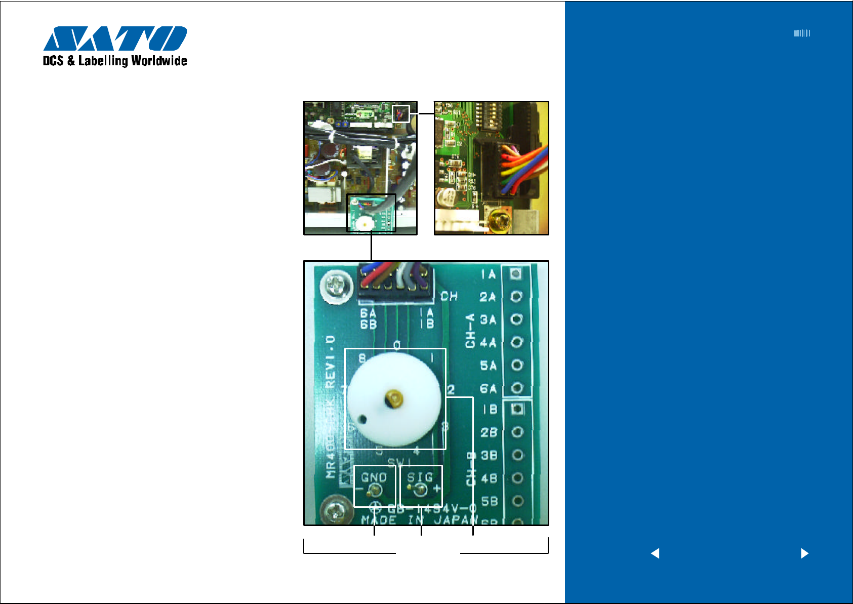
1 Attach the connector from the TP T est Module to the
test port on the MAIN PCB. Note correct positioning
of connector. Nibs on the connector are placed down
on the PCB in the forward position.
2 Attach the ground probe of the Digital Multimeter to
the TP T est Module ground pin (GND PIN).
3 Attach positive probe of the Multimeter to the + SIG
PIN on the TP Test Module terminal.
4 Turn printer power on and rotate the dial to a position
0-5 on the TP T est Module by referring to the diagram
on the next page. Record the values from the Multimeter.
5 Confirm the recorded voltages are within the voltage
range. If not, replace parts or adjust sensor level. Refer
to Check and Adjustment chart.
6 Aft er p erforming test, put the LH cover b ack to
the printer.
Cable to PCB
Cable to TP T est Module
Ground PIN
SIG PIN Dial
TP Test Module
< previous | home | next >
Barcode SATO International Pte Ltd
Page 3
EZ Manual: CL4xxe 3
Electric Checks and Adjustments
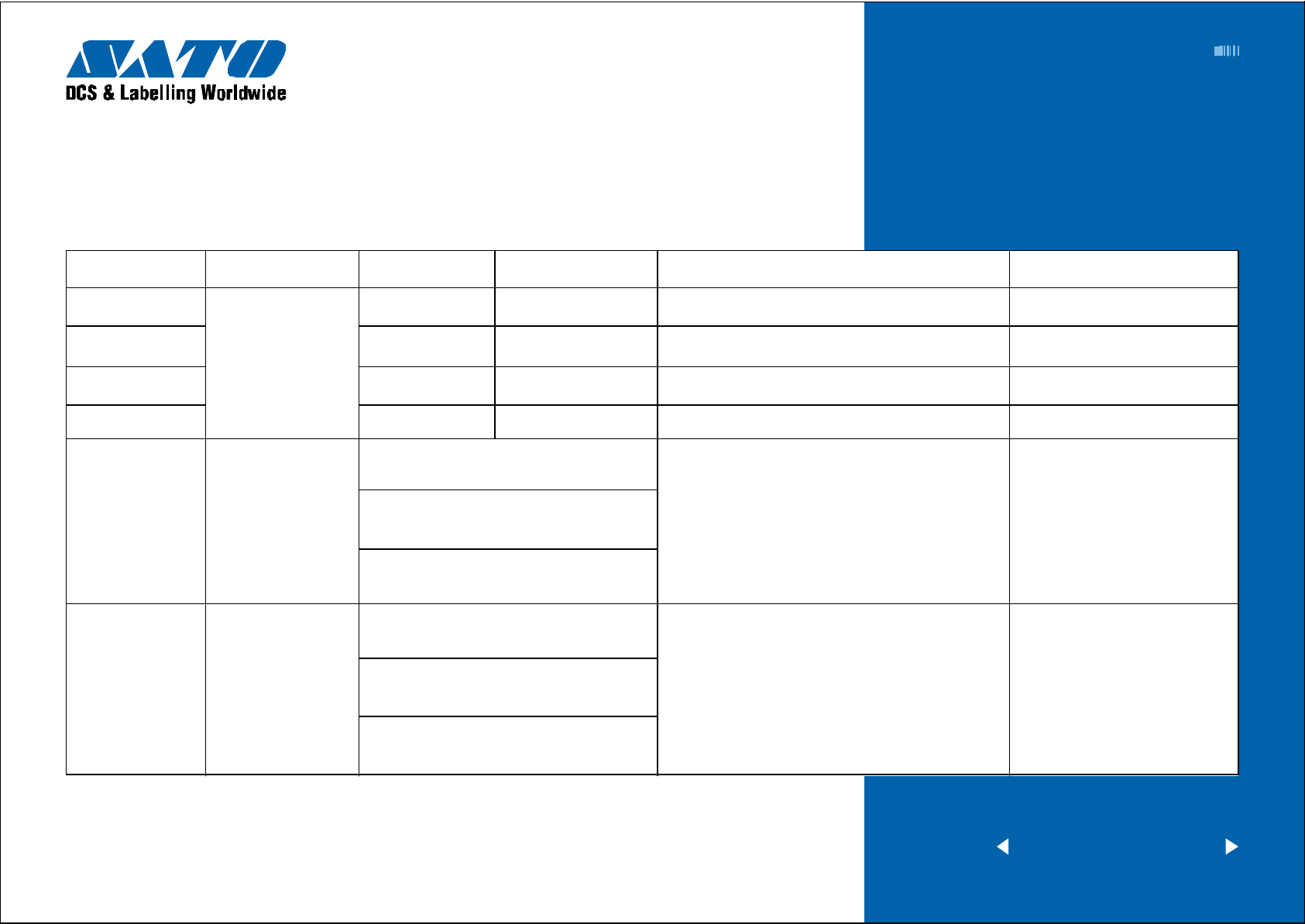
Chart 1
TP TEST POINT CHART
Dial test point Comment Voltage Voltage Range Check pin on TP Test Module and Main PCB Adjustment to VR
0 +5.0 VDC +4.8V to +5.2V CH3A(+5.0V) - CH1A(GND) N/A
1
DC power Supply
2 +3.3 VDC +3.1V to +3.5V CH5A(+3.3V) - CH1A(GND) N/A
3 +24.0 VDC +23.5V to +24.5V CH6A(+24.0V) - CH1A(GND) N/A
4 I-Mark Sensor Level CH1B(+8.4V) - CH1A(GND) VR5
5 Gap sensor Level CH2B - CH1A(GND) VR4
+2.0 VDC +1.9V to +2.1V CH4A(+2.0V) - CH1A(GND) N/A
Low level (Set the blank area
on the sensor) = A
High level (Set the I-mark
on the sensor) = B
High level - Low level =
A - B = m ore than +0.9V
Low level (Set the label backing liner or the
centre hole [in case of the centre hole tag]
on the sensor) = C
High level (Set the label or
tag on the sensor) = D
High level - Low level =
C - D = more than +0.9V
< previous | home | next >
Barcode SATO International Pte Ltd
Page 4

EZ Manual: CL4xxe 4
Potentiometers are located on MAIN PCB.
Adjustment VR Function
VR1(OFS) Pitch Offset Adjustment
VR2(DEM) Not used
VR3(CE) Not used
VR4(GAP) Gap Sensor Level Adjustment
VR5(IM) I-M ark Sensor Level Adjustment
Electric Checks and Adjustments
Chart 2
VR5 I-mark
VR4 Gap
VR1 Offset
VR2 DEM VR3 CE
MAIN PCB
< previous | home | next >
Barcode SATO International Pte Ltd
Page 5
EZ Manual: CL4xxe 5
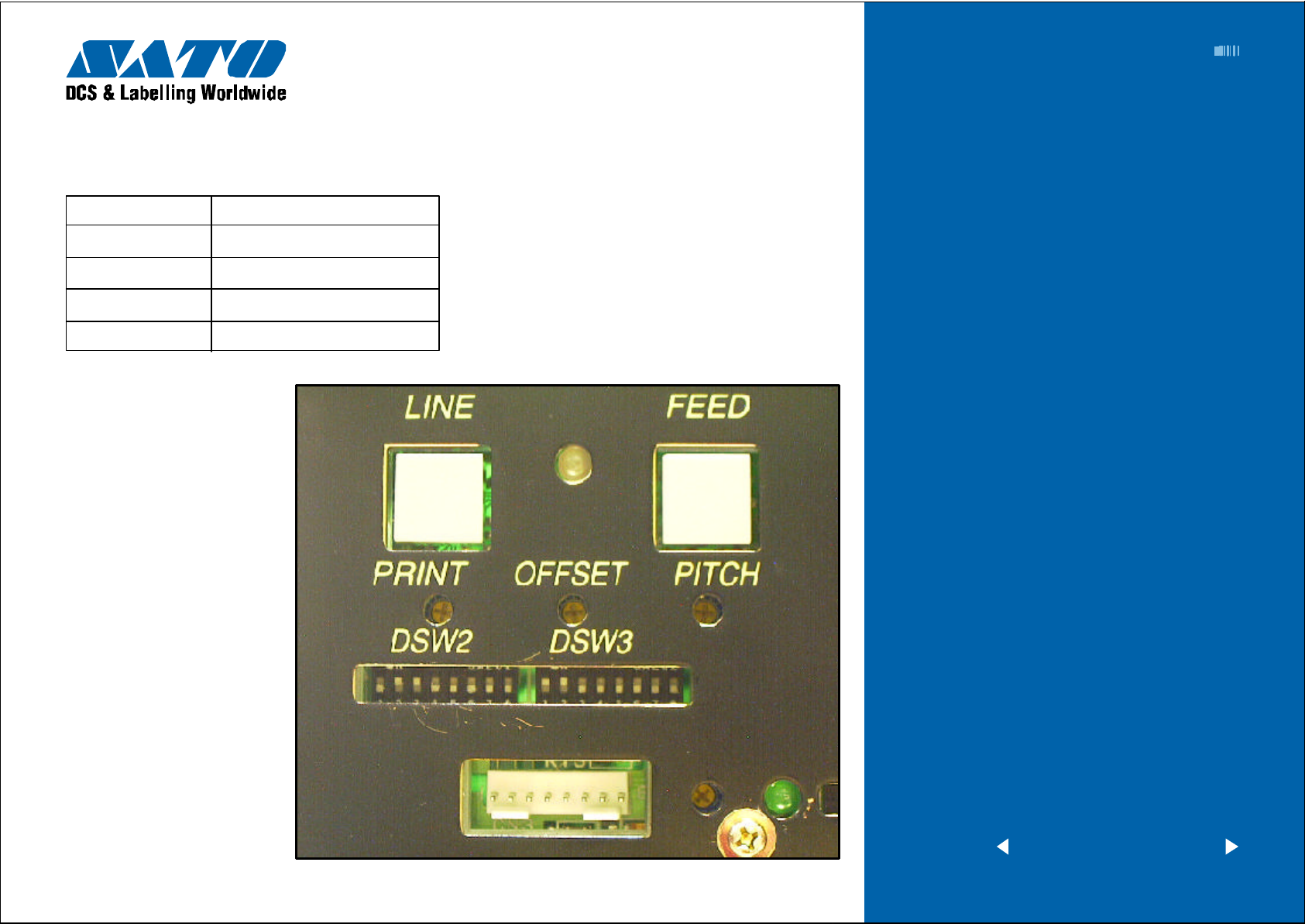
Potentiometers are located on FRONT P ANEL
Adjustment VR Function
PRINT (VR1) Print Darkness Adjustm ent
OFFSET (VR2) Label Stop Position Adjustment
PITCH (VR3) Print Position Adjustment
Label T ake Sensor Dispenser Level Adjustm ent
Electric Checks and Adjustments
Chart 3
< previous | home | next >
Barcode SATO International Pte Ltd
Page 6
EZ Manual: CL4xxe 6
Excessive ribbon unwind and rewind tension will result in
variable motion and could be the cause of print quality
problems.
Ensure the ribbon rewind and unwind tensions are within
specifications or adjustment of either clutch is necessary.
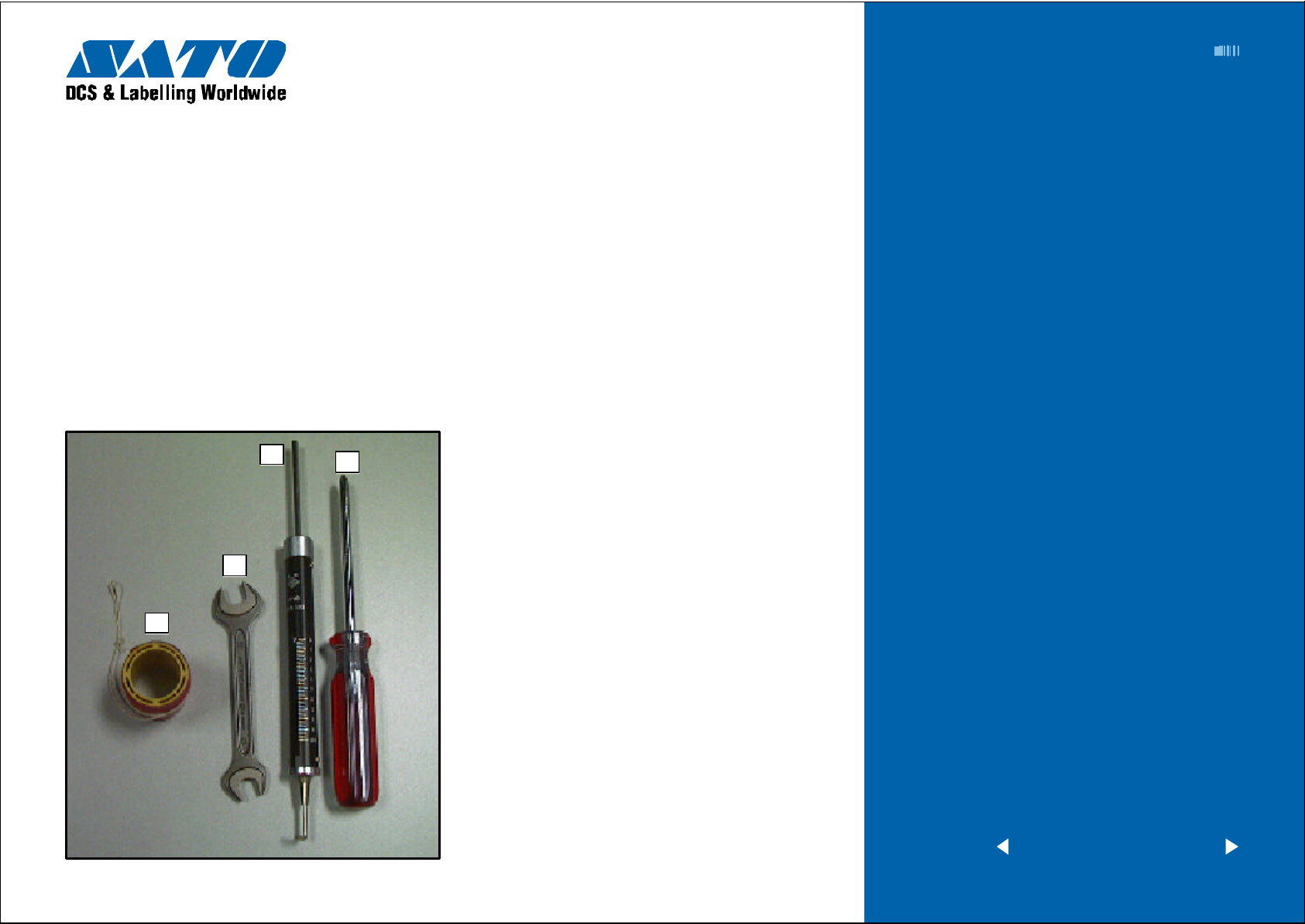
Required equipment
1 Empty Ribbon Core and String
2 12mm Wrench
3 2kg T ension Gauge
4 “+” Screwdriver (JIS No.2 equivalent)
3
2
4
STEPS
1 Sw itch t he printer OFF a nd disconnect the
power cable.
2 Open the top and front access door. Remove the
ribbon and label stock if installed.
3 Attach string to an empty ribbon core and place on
the Ribbon Spindle. W ind the string tightly around the
ribbon core in single layer and in clockwise direction.
Attach the end of the string to the tension gauge.
4 Gradually lift the tension gauge and pull the string,
unwinding it from the core. Once the spindle starts to
move, the gauge should indicate 950 to 1050 grams
of tension for ribbon rewind, and 450 to 550 grams of
tension for ribbon unwind. Refer to pictures on the
next page.
Ribbon Clutch
Adjustment
1
5 T o adjust the clutch, loosen the locking screw and
move the adjust nut CW for more tension and CCW
for less tension. Tighten the locking screw and repeat
steps 3 and 4 until the correct tension is achieved.
< previous | home | next >
Barcode SATO International Pte Ltd
Page 7

EZ Manual: CL4xxe 7
Ribbon Clutch
Adjustment continued
Ribbon Rewind Clutch
T ension Guage T ension Guage
Empty Ribbon Core
450g-550g Unwind
Empty Ribbo n Core
Locking Screw is inside Adjust Nut
Adjust Nut
950g-1050g Rewind
Ribbon Unwind Clutch
< previous | home | next >
Barcode SATO International Pte Ltd
Page 8

Minor Adjustment
EZ Manual: CL4xxe 8
Print Head Position
Required equipment
10mm Open End Wrench
“+” Screwdriver (JIS No.2 equivalent)
T o adjust the print head alignment and ensure consistent
quality ac ross label, perform the following steps:
STEPS
1 Loosen the screws on the head plate. Print user test
patte rn. Realign the print head by prying the adjust
plate forward or backward with flat blade screwdriver.
Refer to illustrations and note adjustment marks.
2 Tighten the screws.
Alignment
Adjustment Marks
Screws
Print head “open” lever
< previous | home | next >
Barcode SATO International Pte Ltd
Page 9

Major Adjustment
EZ Manual: CL4xxe 9
Print Head Position
Required equipment
“+” Screwdriver (JIS No.2 equivalent)
T o further optimize print quality, especially when using
thick label stock, additional adjustments are possible.
Perform the following steps using head pattern as a guide.
STEPS
1 Load the ribbon and label stock into the printer.
2 Loosen and adjust screw along slot to move indexing
pointer for maximum print quality.
Alignment continued
Loosen the screw .
Then indexing pointer shifts head BACK WARD/FORWARD
Loosen the screw 1/4 T urn
< previous | home | next >
Barcode SATO International Pte Ltd
Page 10

Minor Adjustment
EZ Manual: CL4xxe 10
Print Head Balance
Required equipment
10mm Wrench
“+” Screwdriver (JIS No.2 equivalent)
T o optimize print quality, perform the following steps to
adjust the Print Head Balance using Factory Test Print.
STEPS
1 Load the ribbon and label stock into the printer.
2 Loosen the screws by 1/4 turn. Please refer to picture.
3 Adjust color by rotating CW or CCW.
4 Tighten screw to secure eccentric nut in place.
5 Loosen and adjust screw along slot to move indexing
pointer maximum print quality.
Adjustment
Loosen the screw 1/4 T urn
Indexing Marks
Use the 10m m wrench to adjust eccentric nut
CW or CCW and tighten screw .
< previous | home | next >
Barcode SATO International Pte Ltd
 Loading...