

Page 1
Operator Manual
For printer model:
Page 2

Copyrights
Any unauthorized reproduction of the contents of this document, in part or whole, is strictly prohibited.
Limitation of Liability
SATO Corporation and its subsidiaries in Japan, the U.S. and other countries make no representations or
warranties of any kind regarding this material, including, but not limited to, implied warranties of
merchantability and fitness for a particular purpose. SATO Corporation shall not be held responsible for errors
contained herein or any omissions from this material or for any damages, whether direct, indirect, incidental or
consequential, in connection with the furnishing, distribution, performance or use of this material.
Specifications and contents in this document are subject to change without notice.
Be sure to perform a virus check for the USB memory before connecting it to the printer. SATO Corporation
shall not be held responsible for any printer malfunctions caused by a virus spread via USB memory.
Trademarks
SATO is a registered trademark of SATO Holdings Corporation and its subsidiaries in Japan, the U.S. and
other countries.
QR Code is a registered trademark of DENSO WAVE INCORPORATED.
®
is a registered trademark of Wi-Fi Alliance.
Wi-Fi
Wi-Fi Direct™, Wi-Fi Protected Setup™, WPA™ and WPA2™ are trademarks of Wi-Fi Alliance.
Cisco, the Cisco logo, and Cisco Systems are trademarks or registered trademarks of Cisco Systems, Inc.
and/or its affiliates in the United States and certain other countries.
Bluetooth is a trademark of Bluetooth SIG, Inc., U.S.A.
®
ENERGY STAR
and ENERGY STAR mark are registered U.S. marks.
ICODE, I-CODE, and SLI are registered trademarks of NXP B.V.
®
MIFARE
is a registered trademark of NXP B.V.
Tag-it™ is a trademark of Texas Instruments.
my-d™ is a registered trademark of Infineon Technologies AG.
FeliCa is a registered trademark of Sony Corporation.
FeliCa is a contactless IC card technology developed by Sony Corporation.
Android is a trademark of Google Inc.
All other trademarks are the property of their respective owners.
Version: GBS-CL4NX_CL6NX-r08-01-08-16OM
© 2016 SATO Corporation. All rights reserved.
Page 3

Table of Contents
Table of Contents ................................................................................... 1
Before You Start ..................................................................................... 7
Features of the Product............................................................................................ 7
Safety Precautions.................................................................................................... 8
Precautions for Installation and Handling ............................................................ 11
Regulatory Approval............................................................................................... 12
1 Parts Identification............................................................................. 15
1.1 Parts Identification of the Printer .................................................................... 15
1.1.1 Front View ............................................................................................................... 15
1.1.2 Rear View ................................................................................................................ 16
1.1.3 Internal View............................................................................................................ 17
1.2 Parts on the Operator Panel............................................................................. 18
1.2.1 Operator Panel ........................................................................................................ 18
1.2.2 LED Indicator........................................................................................................... 19
2 Installing the Printer .......................................................................... 21
2.1 Installation Precautions.................................................................................... 21
2.2 Installation Space.............................................................................................. 22
2.2.1 Front View (CL4NX) ................................................................................................ 22
2.2.2 Front View (CL6NX) ................................................................................................ 22
2.2.3 Side View (CL4NX/CL6NX) ..................................................................................... 23
2.2.4 Bottom View (CL4NX) ............................................................................................. 24
2.2.5 Bottom View (CL6NX) ............................................................................................. 24
2.3 Checking the Bundled Accessories ................................................................ 25
2.4 Connecting the Interface Cable ....................................................................... 26
2.4.1 Available Interfaces ................................................................................................. 26
2.4.2 Interface Settings..................................................................................................... 27
2.4.3 NFC Interface Connection ....................................................................................... 27
2.5 Connecting the Power Cord............................................................................. 28
2.6 Power On/Off the Printer .................................................................................. 29
2.6.1 Power On the Printer ............................................................................................... 29
2.6.2 Power Off the Printer ............................................................................................... 30
CL4NX/CL6NX Operator Manual
1
Page 4

Table of Contents
2.7 Starting Up the Printer (Startup Guide)........................................................... 31
2.7.1 Startup Screen......................................................................................................... 31
2.7.2 Language Selection................................................................................................. 31
2.7.3 Region Setting with Optional RTC........................................................................... 32
2.7.4 City Setting with Optional RTC ................................................................................ 32
2.7.5 Date Setting with Optional RTC............................................................................... 32
2.7.6 Time Setting with Optional RTC .............................................................................. 33
2.7.7 Print Method Setting ................................................................................................ 33
2.7.8 Ribbon Setting ......................................................................................................... 34
2.7.9 Setting the Media Sensor Type ............................................................................... 34
2.7.10 Media Setting......................................................................................................... 35
2.7.11 Confirmation Screen.............................................................................................. 36
2.7.12 Startup Guide Cancelation .................................................................................... 36
3 Loading the Ribbon and Media........................................................... 37
3.1 Checking the Ink Side of the Ribbon............................................................... 37
3.2 Loading the Ribbon .......................................................................................... 38
3.3 Removing the Ribbon ....................................................................................... 41
3.4 Usable Media ..................................................................................................... 42
3.4.1 Adjusting the Position of the Media Sensor............................................................. 42
3.5 Loading Media ................................................................................................... 43
3.5.1 Loading Media Roll.................................................................................................. 43
3.5.2 Loading Fan-fold Media........................................................................................... 45
3.5.3 Loading Media with the Optional Cutter .................................................................. 46
3.5.4 Loading Media with an Optional Dispenser and Liner Discharge Outlet ................. 46
3.5.5 Loading Media with an Optional Dispenser and Liner Rewinder............................. 47
3.5.6 Removing the Liner from the Rewinder ................................................................... 49
4 Operation and Configuration .............................................................. 51
4.1 Display and Operation ...................................................................................... 51
4.1.1 Online Mode/Offline Mode....................................................................................... 51
4.1.2 Status Icon............................................................................................................... 52
4.1.3 Error Icon................................................................................................................. 55
4.1.4 Guidance Video ....................................................................................................... 58
4.1.5 Adjusting the Print Settings During Printing............................................................. 61
4.1.6 Canceling the Print Job ........................................................................................... 62
4.2 Settings Mode.................................................................................................... 63
4.2.1 Changing to Settings Mode ..................................................................................... 63
4.2.2 Log In to/Log Out of the Settings Mode................................................................... 64
4.2.3 Item Selection.......................................................................................................... 65
4.2.4 Setting Value Input or Selection .............................................................................. 66
4.3 Settings Menu Tree Structure .......................................................................... 69
CL4NX/CL6NX Operator Manual
2
Page 5

Table of Contents
4.4 Details of the Settings Menu Screen ............................................................... 83
4.4.1 Shortcut Menu ......................................................................................................... 83
4.4.2 Printing Menu .......................................................................................................... 84
4.4.3 Interface Menu....................................................................................................... 105
4.4.4 Applications Menu ................................................................................................. 177
4.4.5 System Menu......................................................................................................... 205
4.4.6 Tools Menu............................................................................................................ 216
4.4.7 Information Menu................................................................................................... 238
4.5 Web Configuration .......................................................................................... 248
4.5.1 Dashboard ............................................................................................................. 248
4.5.2 Settings.................................................................................................................. 249
4.5.3 Tools...................................................................................................................... 251
4.5.4 Certificates............................................................................................................. 253
5 Cleaning and Performing Printer Adjustments ................................ 255
5.1 Maintenance .................................................................................................... 255
5.2 Maintenance of the Print Head and Platen Roller ........................................ 256
5.2.1 Maintenance using the Cleaning Kit ...................................................................... 256
5.2.2 Additional Procedure for the Optional Linerless Cutter Kit (CL4NX only).............. 259
5.2.3 Maintenance using the Cleaning Sheet................................................................. 260
5.3 Adjusting the Base Reference Point ............................................................. 262
5.3.1 About the Base Reference Point ........................................................................... 262
5.3.2 Adjusting the Print Position.................................................................................... 263
5.3.3 Adjusting the Media Stop Position......................................................................... 265
5.3.4 Notes on the Stop/Cut Position of Different Media ................................................ 266
5.4 Adjusting the Print Quality............................................................................. 268
5.4.1 Adjusting the Print Darkness ................................................................................. 268
5.4.2 Adjusting the Print Speed ...................................................................................... 269
5.5 Adjusting the Buzzer Volume ........................................................................ 271
5.6 Adjusting the Head Pressure Balance .......................................................... 272
5.6.1 Head Pressure Setting .......................................................................................... 272
5.6.2 Pressure Balance Setting ...................................................................................... 273
6 Troubleshooting................................................................................ 275
6.1 When an Error Message Occurs.................................................................... 275
6.1.1 More Information about Command Error............................................................... 283
6.2 When the LED Lights Red/Blue ..................................................................... 285
6.3 Troubleshooting Table ................................................................................... 286
6.3.1 No Power/Nothing on the Screen .......................................................................... 286
6.3.2 Cannot Feed the Media ......................................................................................... 286
6.3.3 Can Feed the Media but Cannot Print ................................................................... 287
6.3.4 Bad Print Quality.................................................................................................... 288
6.3.5 Incorrect Print Position .......................................................................................... 289
6.3.6 Cannot Read Barcodes When Using the Barcode Check Function ...................... 290
CL4NX/CL6NX Operator Manual
3
Page 6

Table of Contents
6.4 Interface Troubleshooting.............................................................................. 291
6.4.1 USB Interface ........................................................................................................ 291
6.4.2 LAN Ethernet Interface .......................................................................................... 291
6.4.3 Bluetooth Interface ................................................................................................ 291
6.4.4 NFC Interface ........................................................................................................ 292
6.4.5 RS-232C Interface................................................................................................. 292
6.4.6 IEEE1284 Interface ............................................................................................... 292
6.4.7 External Signal Interface (EXT) ............................................................................. 293
6.4.8 Wireless LAN Interface.......................................................................................... 293
7 Appendix ........................................................................................... 295
7.1 List of Initial Values ........................................................................................ 295
7.1.1 Printing Menu ........................................................................................................ 295
7.1.2 Interface Menu....................................................................................................... 298
7.1.3 Applications Menu ................................................................................................. 308
7.1.4 System Menu......................................................................................................... 311
7.1.5 Tools Menu............................................................................................................ 313
7.1.6 Information Menu................................................................................................... 315
7.2 Media Sensor Positions and Media Stop Positions..................................... 316
7.3 Replacing the Print Head................................................................................ 318
7.4 Replacing the Platen Roller............................................................................ 320
7.4.1 Guideline to Replace the Linerless Platen Roller (CL4NX only)............................ 321
7.5 Optional RFID Configuration (CL4NX only) .................................................. 322
7.5.1 Printing RFID Tag Errors ....................................................................................... 325
7.5.2 RFID Error and Reset Timing ................................................................................ 329
7.5.3 External (EXT) Signal Interfaces when RFID Mode is Enabled ............................ 332
7.5.4 RFID Printing Tips ................................................................................................. 332
7.6 Optional Barcode Check Function Configuration........................................ 333
7.6.1 Basic Specifications of the Barcode Check Function ............................................ 333
7.6.2 Setting Up the Barcode Checker ........................................................................... 339
7.6.3 Changing How the RS-232C Interface is Used
(When Using the KEYENCE Barcode Checkers)........................................................... 340
7.6.4 Doing a Test Read with the Barcode Checker ...................................................... 342
7.6.5 Enabling the Barcode Check ................................................................................. 345
7.6.6 Restrictions for the Barcode Check Function ........................................................ 349
7.7 Printer Specifications ..................................................................................... 351
7.7.1 Hardware ............................................................................................................... 351
7.7.2 Ribbon and Media ................................................................................................. 354
7.7.3 Interface................................................................................................................. 356
7.7.4 Built-in Functions ................................................................................................... 357
7.7.5 Printer Languages ................................................................................................. 357
7.7.6 Fonts/Symbols/Barcodes....................................................................................... 358
7.7.7 Options .................................................................................................................. 361
7.7.8 Accessories ........................................................................................................... 361
7.7.9 Standards .............................................................................................................. 362
CL4NX/CL6NX Operator Manual
4
Page 7

Table of Contents
7.8 Interface Specifications.................................................................................. 363
7.8.1 USB Interface ........................................................................................................ 364
7.8.2 LAN Ethernet Interface .......................................................................................... 365
7.8.3 Bluetooth Interface ................................................................................................ 366
7.8.4 NFC Interface ........................................................................................................ 366
7.8.5 RS-232C Interface................................................................................................. 367
7.8.6 IEEE1284 Interface ............................................................................................... 369
7.8.7 External Signal Interface (EXT) ............................................................................. 371
7.8.8 Wireless LAN Interface.......................................................................................... 380
CL4NX/CL6NX Operator Manual
5
Page 8

Table of Contents
This page is intentionally left blank.
CL4NX/CL6NX Operator Manual
6
Page 9

Before You Start
Thank you for purchasing this SATO CL4NX/CL6NX printer (hereafter referred to as “the printer”).
This manual supplies basic information on how to operate the printer. Read the manual carefully to
understand each function before operation.
Features of the Product
This SATO CL4NX/CL6NX printer is a high-performance labeling system with a robust casing made of
metal and equipped with versatile functions. The main features of the printer are as follows:
• Simple and stylish design
• High-quality printing
• Designed for better usability
• Equipped with high legibility TFT color 3.5 inch LCD and LED
• Onboard Guidance Videos
• Print head and platen roller can be replaced without using extra tools
• Supports a 600 m ribbon
• Supports thirty-one languages for display and forty-seven languages for printing scalable fonts
• Supports various communication interfaces
• Supports protocols such as IPv6, SNMP and NTP
• Certified by Wi-Fi alliance
• Compatible with Cisco CCX V4.0
SATO CL4NX/CL6NX printer has tested compatible with Cisco CCX, version 4.0.
The Cisco Compatible logo signifies that SATO product has undergone
interoperability testing by SATO together with Cisco and a third-party test house
based on testing criteria set by Cisco.
SATO is solely responsible for the support and warranty of its product. Cisco
makes no warranties, express or implied, with respect to SATO product or its inter
operation with the listed Cisco product(s) and disclaims any implied warranties of
merchantability, fitness for a particular use, or against infringement.
®
• Conforms to international ENERGY STAR
program
The products described herein comply with the requirements of the ENERGY
STAR. As an ENERGY STAR Partner, SATO Corporation has determined that this
product meets the ENERGY STAR guidelines for energy efficiency.
CL4NX/CL6NX Operator Manual
7
Page 10
Before You Start
Safety Precautions
This section describes how to safely operate the printer. Be sure to read and understand all instructions
carefully before you install and use the printer.
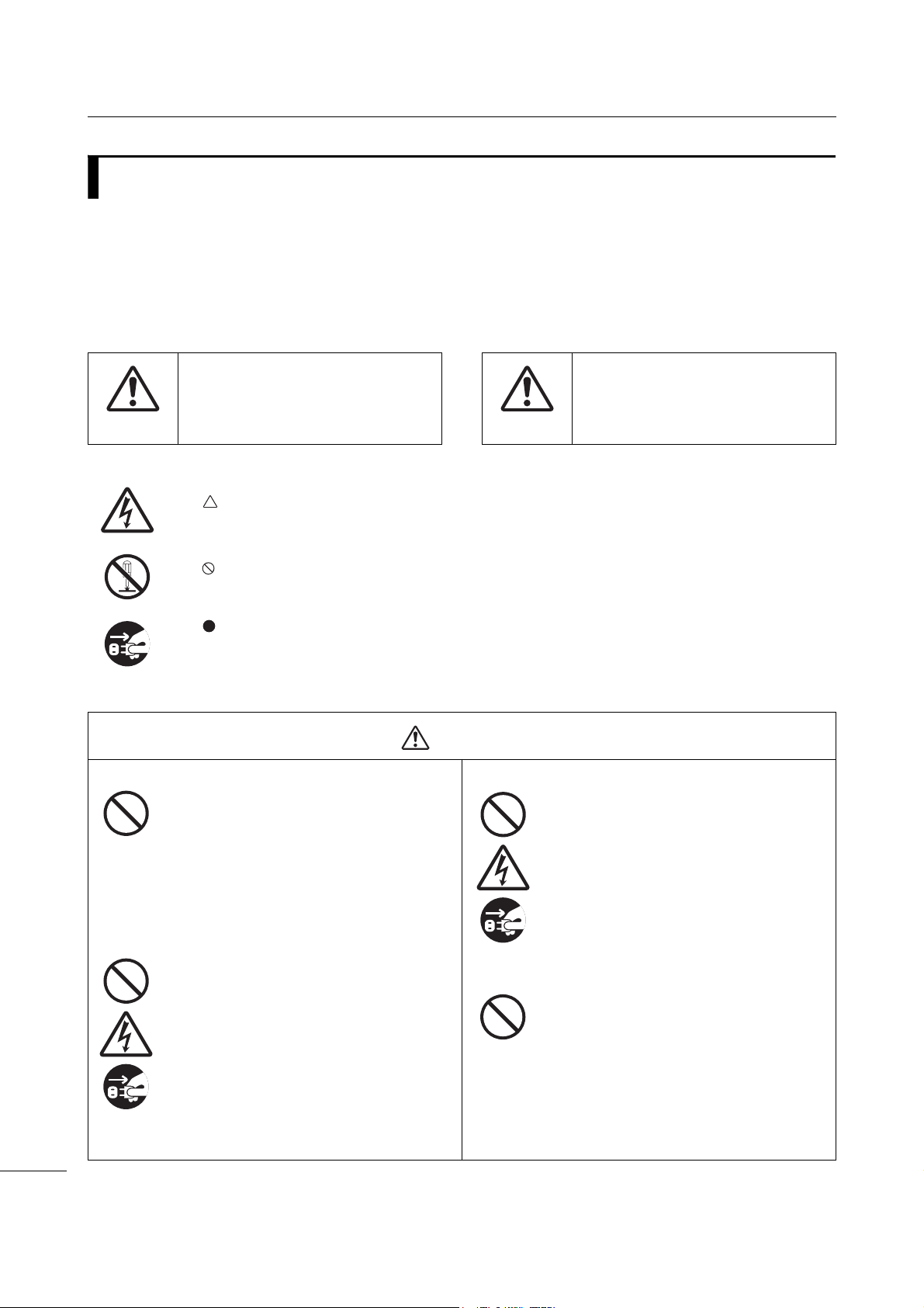
Pictographic Symbols
This operator manual and printer labels use a variety of pictographic symbols. These symbols show the safe
and correct operation of the printer and how to prevent injury to others and property damage. The symbol
explanations are as follows.
The Warning symbol indicates that
you can cause death or serious
injury if you do not follow the
Warning
Example Pictographs
Place the printer on a stable area.
Do not place containers filled with liquid on the
printer.
instruction or procedure.
The pictograph means “Caution is required”. The pictograph includes a
specified warning symbol (for example, the left symbol shows electric shock).
The pictograph means “Must not be done”. The pictograph includes a specified
prohibited symbol (for example, the left symbol means “Disassembly prohibited”).
The pictograph means “Must be done”. The pictograph includes a specified
mandate action symbol (for example, the left symbol means “Disconnect the
power plug from the outlet”).
• Place the printer on a stable area. Do not
place the printer on an unstable table,
slanted surface or an area subject to
strong vibration. If the printer falls off or
topples, it could cause injury to
someone.
• Do not place flower vases, cups, or other
containers filled with liquids, on the
printer. If any liquid spills into the printer,
immediately power off the printer and
disconnect the power plug from the
outlet. Then contact your SATO reseller
or technical support center. If you
operate the printer in this condition, it
could cause a fire or electric shock.
The Caution symbol indicates that
you can cause injury or property
damage if you do not follow the
Caution
instruction or procedure.
Warning
Do not place objects into the printer.
• Do not place metal or flammable objects
inside the printer’s opening. If a foreign
object gets into the printer, immediately
power off the printer and disconnect the
power plug from the outlet. Then contact
your SATO reseller or technical support
center. If you operate the printer in this
condition, it could cause a fire or electric
shock.
Do not use other than the specified voltage.
• Do not use other than the specified
voltage (AC 100 V - 240 V). Doing so
could cause a fire or electric shock.
CL4NX/CL6NX Operator Manual
8
Page 11
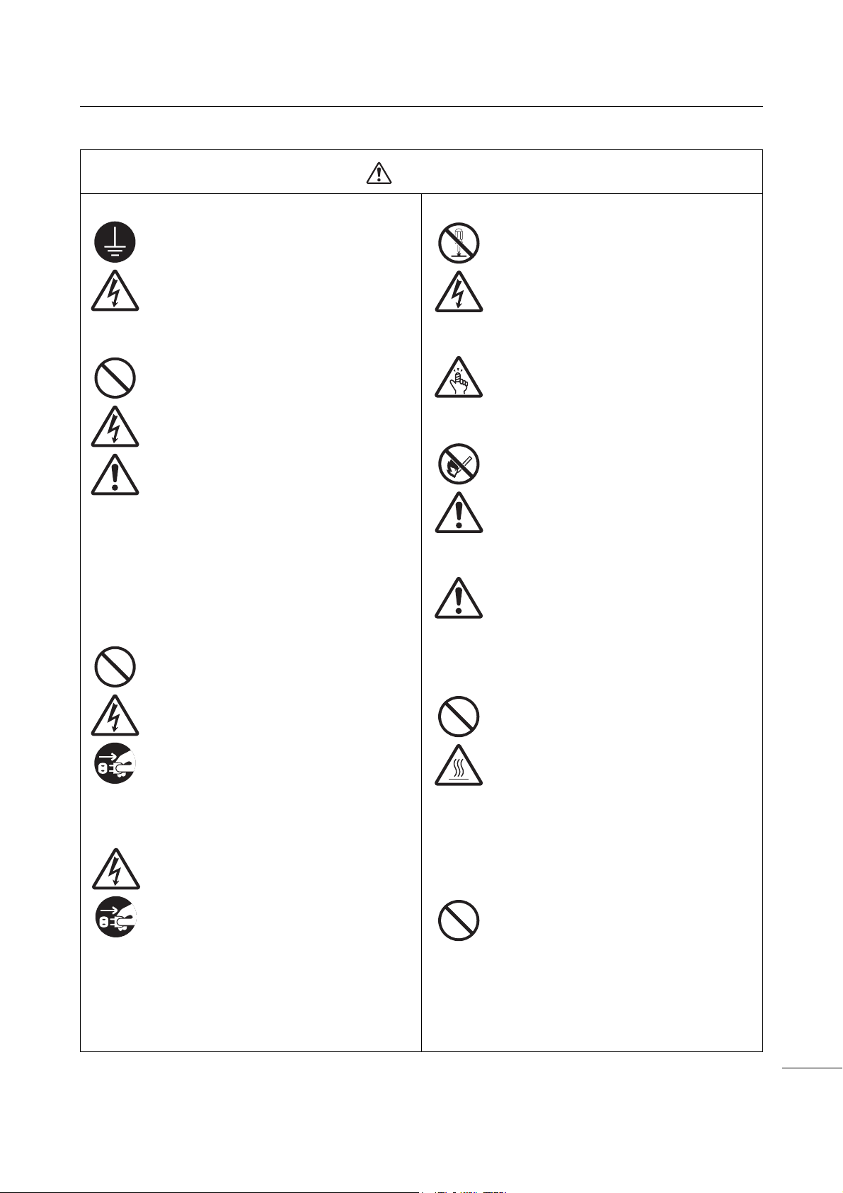
Warning
Before You Start
Always ground connections.
• Always connect the printer’s ground wire
to a ground. Not grounding the ground
wire could cause an electric shock.
Handling the power cord
• Do not break or change the power cord.
Do not place heavy objects on the power
cord, heat it, or pull it. Doing so could
cause damage to the power cord and
cause a fire or electric shock.
• If the power cord becomes damaged
(core is exposed, wires broken, etc.),
contact your SATO reseller or technical
support center. Using the power cord in
this condition could cause a fire or
electric shock.
• Do not change, overly bend, twist, or pull
the power cord. Using the power cord in
such a way could cause a fire or electric
shock.
When the printer has been dropped or broken
• If the printer is dropped or broken,
immediately power off the printer and
disconnect the power plug from the
outlet. Contact your SATO reseller or
technical support center. Using the
printer in this condition could cause a fire
or electric shock.
Do not use the printer when something is
unusual about it.
• Continuing to use the printer in the event
something is unusual about it, such as
smoke or unusual smells coming from it,
could cause a fire or electric shock.
Immediately power off the printer and
disconnect the power plug from the
outlet. Then contact your SATO reseller
or technical support center for repairs.
Under no circumstances should you
attempt repairs on your own; it is too
dangerous.
Do not disassemble the printer.
• Do not disassemble or modify the printer.
Doing so could cause a fire or electric
shock. Contact your SATO reseller or
technical support center to perform
internal inspections, adjustments, and
repairs.
Regarding the cutter
• Do not touch the cutter with your hands,
nor place objects into the cutter. Doing
so could cause an injury.
Using the head cleaning fluid
• Use of flame or heat around the head
cleaning fluid is prohibited. Do not heat it
or subject it to flames.
• Keep the fluid out of reach of children. If
a child accidentally drinks the fluid,
immediately consult with a physician.
Laser beam
• Do not look into the laser radiation
window of the barcode checker, and do
not direct the laser beam at someone. If
the laser beam hits eyes, it may cause
visual disturbance.
Print head
• The print head will become hot after
printing. Be careful not to touch it when
replacing media or cleaning immediately
after printing, to avoid being burned.
• Touching the edge of the print head
immediately after printing could cause an
injury. Use caution when replacing the
media or cleaning the print head.
• Never replace the print head if you have
not received the correct training.
Do not use in hazardous locations.
• The printer is not explosion proof
certified.
• Do not use in a potentially explosive
environment or atmosphere.
CL4NX/CL6NX Operator Manual
9
Page 12
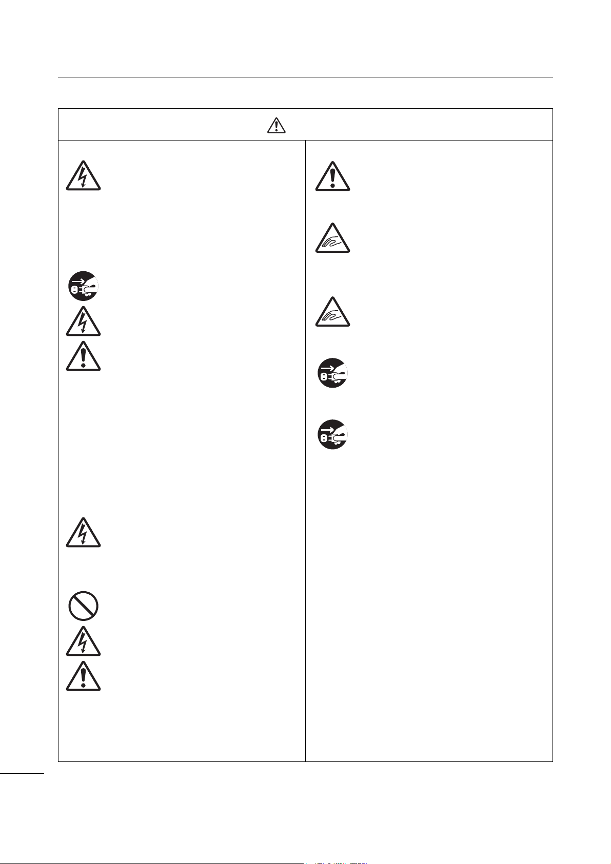
Before You Start
Caution
Do not use in areas of high humidity.
• Do not use the printer in areas of high
humidity or where condensation forms. If
condensation forms, immediately power
off the printer and do not use the printer
until it dries. Using the printer while
condensation is on it could cause an
electric shock.
Carrying the printer
• When moving the printer, always
disconnect the power cord from the
outlet and check to make sure that all
external wires are disconnected before
moving it. Moving the printer with the
wires still connected could cause
damage to the cords or connecting
wires, resulting in a fire or electric shock.
• Do not carry the printer while it contains
media. The media could fall out and
cause an injury.
• When setting the printer on the floor or a
stand, be sure not to get your fingers or
hands pinched under the printer feet.
• Do not carry the printer with the barcode
checker stand installed. The barcode
checker stand could fall out and cause
injury.
Handling the barcode checker stand kit
• Be careful avoid injury from pointed part
of the barcode checker stand kit.
Top cover
• Be careful not to get your fingers pinched
when opening or closing the top cover.
Also, be careful that the top cover does
not slip off and drop.
Loading media
• When loading a media roll, be careful not
to get your fingers pinched between the
media roll and the supply unit.
When not using the printer for a long time
• When not using the printer for a long
time, disconnect the power cord from the
outlet to maintain safety.
During maintenance and cleaning
• When maintaining and cleaning the
printer, disconnect the power cord from
the outlet to maintain safety.
Power supply
• If your hands are wet, do not operate the
power button, connect the power cord or
disconnect the power cord. Doing so
could cause an electric shock.
Power cord
• Keep the power cord away from hot
devices. Placing the power cord near hot
devices could cause the cord’s covering
to melt and cause a fire or electric shock.
• When disconnecting the power cord from
the outlet, be sure to hold the plug.
Pulling the cord could expose or break
the wires and cause a fire or electric
shock.
• The power cord set that comes with the
printer is designed especially for this
printer. Do not use it with any other
electrical devices.
CL4NX/CL6NX Operator Manual
10
Page 13

Before You Start
Place the printer on a surface that is flat and level.
If the surface is not flat and level, this may cause bad
print quality. This may also cause a malfunction and
decrease the life span of the printer.
Do not place the printer on a location that
produces vibration.
Giving serious vibration or shock to the printer may
cause a malfunction and shorten the life span of the
printer.
Keep the printer out of high temperature and
humidity.
Avoid locations subject to extreme or fast changes in
temperature or humidity.
Do not place the printer in a location subject to
water or oil.
Do not place the printer in a location where it will be
exposed to water or oil. Water or oil entering inside
the printer may cause a fire, electric shock or
malfunction.
Avoid dust.
Dust build up may result in bad print quality.
Keep out of direct sunlight.
This printer has a built-in optical sensor. Exposure to
direct sunlight will make the sensor less responsive
and may cause the media to be sensed incorrectly.
Close the top cover when printing.
This printer requires an AC power supply.
Be sure to connect the printer to an AC power
supply.
Connect the power cord to a grounded power
outlet.
Make sure that the printer is connected to a
grounded power outlet.
Supply a stable source of electricity to the printer.
When using the printer, do not share its power outlet
with other electrical devices that could cause power
fluctuations and performance issues with your
printer.
Precautions for Installation and Handling
Printer operation can be affected by the printer environment.
Refer to the following instructions for installation and handling of the CL4NX/CL6NX printer.
Select a Safe Location
Power Supply
CL4NX/CL6NX Operator Manual
11
Page 14

Before You Start
Regulatory Approval
FCC Warning
You are cautioned that changes or modifications not expressly approved by the party responsible for
compliance could void your authority to operate the equipment.
This device complies with Part 15 of the FCC Rules. Operation is subject to the following two conditions:
(1) this device may not cause harmful interference, and (2) this device must accept any interference
received, including interference that may cause undesired operation.
This equipment has been tested and found to comply with the limits for a Class B digital device, pursuant
to Part 15 of the FCC Rules. These limits are designed to provide reasonable protection against harmful
interference in a residential installation. This equipment generates, uses and can radiate radio frequency
energy and, if not installed and used in accordance with the instructions, may cause harmful interference
to radio communications.
However, there is no guarantee that interference will not occur in a particular installation.
If this equipment does cause harmful interference to radio or television reception, which can be
determined by turning the equipment off and on, the user is encouraged to try to correct the interference
by one or more of the following measures:
• Reorient or relocate the receiving antenna.
• Increase the separation between the equipment and the receiver.
• Connect the equipment into an outlet on a circuit different from that to which the receiver is connected.
• Consult the dealer or an experienced radio/TV technician for help.
Shielded cable must be used in order to comply with the emission limits.
FCC Statement for Optional Wireless LAN
This device complies with RF radiation exposure limits set forth for an uncontrolled environment.
The antenna used for this transmitter must be installed to provide a separation distance of at least 20 cm
from all people and must not be collocated or operating in conjunction with any other antenna or
transmitter.
Bluetooth/Wireless Communication
Compliance Statement
This product has been certified for compliance with the relevant radio interference regulations of your
country or region. To make sure continued compliance, do not:
• Disassemble or modify this product.
• Remove the certificate label (serial number seal) affixed to this product.
Use of this product near microwave and/or other wireless LAN equipment, or where static electricity or
radio interference is present, may shorten the communication distance, or even disable communication.
CL4NX/CL6NX Operator Manual
12
Page 15

Before You Start
Industry Canada (IC) Statement for Bluetooth
This device complies with Industry Canada license-exempt RSS standard(s). Operation is subject to the
following two conditions:
• This device may not cause interference.
• This device must accept any interference, including interference that may cause undesired operation
of the device.
This equipment complies with IC radiation exposure limits set forth for an uncontrolled environment and
meets RSS-102 of the IC radio frequency (RF) Exposure rules. This equipment should be installed and
operated keeping the radiator at least 20 cm or more away from person’s body (excluding extremities:
hands, wrists, feet and ankles).
Le présent appareil est conforme aux CNR d’Industrie Canada applicables aux appareils radio exempts
de licence. L’exploitation est autorisée aux deux conditions suivantes :
• L’appareil ne doit pas produire de brouillage.
• L’utilisateur de l’appareil doit accepter tout brouillage radioélectrique subi, même si le brouillage est
susceptible d'en compromettre le fonctionnement.
Cet équipement est conforme aux limites d’exposition aux rayonnements énoncées pour un
environnement non contrôlé et respecte les règles d’exposition aux fréquences radioélectriques (RF)
CNR-102 de l’IC. Cet équipement doit être installé et utilisé en gardant une distance de 20 cm ou plus
entre le dispositif rayonnant et le corps (à l’exception des extrémités : mains, poignets, pieds et
chevilles).
Disposal of Old Electrical & Electronic Equipment (Applicable in the European Union
and other European countries with separate collection systems)
A product marked with this symbol on itself or on its packaging shall not be treated as
household waste. Instead, it shall be handed over to an appropriate collection point for
the recycling of electrical and electronic equipment in accordance with local regulations.
Inappropriate waste handling of this product may cause detrimental consequences for
the environment and damage to human health. The recycling of materials will help to
conserve natural resources and contribute to your community. For more detailed
information on recycling of this product, contact your local municipal organization, your
household waste disposal service or the dealer where you purchased the product.
EN55022 Warning
This is a class A product.
In a domestic environment, this product may cause radio interference, in which case the user may be
required to take adequate measures.
EN55022 Warnung
Warnung! Dies ist eine Einrichtung der Klasse A.
Diese Einrichtung kann im Wohnbereich Funkstörungen verursachen. In diesem Fall kann vom Betreiber
verlangt werden, angemessene Maßnahmen durchzuführen.
Das Gerät ist nicht für die Benutzung im unmittelbaren Gesichtsfeld am Bildschirmarbeitsplatz
vorgesehen. Um störende Reflexionen am Bildschirmarbeitsplatz zu vermeiden, darf dieses Produkt
nicht im unmittelbaren Gesichtsfeld platziert werden.
CL4NX/CL6NX Operator Manual
13
Page 16
Before You Start
㺞⽰䈛ᴿ∈ᴿᇩ⢟䍞㠩ቇ൞䈛䜞ԬⲺḆжൽ䍞ᶆѣⲺ䠅䎻࠰
GB/T 26572ć⭫ᆆؗᚥӝѣᴿ∈ᴿᇩ⢟䍞Ⲻ䲆䠅㾷≸ĈⲺḽ㿺ᇐȾ
(Pb)
(Hg)
ᵰಞ〦ᶗ⸷ᢉদᵰ
䜞Ԭ〦
ᴿ∈ᴿᇩ⢟䍞ᡌݹ㍖
䫻⊔
দ⭫䐥ᶵ
(Cd)
䭿
(Cr6+)
ޣԭ䬢
(PBB)
ཐ⓪㚊㤥
(PBDE)
ཐ⓪ӂ
㤥䟐
⭫ⓆȽӚ⍷䖢ᦘಞ
⭫⊖
✣ᮅཪ
Ƚ
⏨Წᱴ⽰ኅ
⭫ࣞᵰ
Ƚ
࠽㓮ᵰ
ṇ㜸ABS
Ƚ
PCㅿ
䠇ኔ䫷
Ƚ
䶔䫷䠇ኔ
⭫㔼ㅿ
㻻ᶆᯏ㓮ⴈㅿ
㺞⽰䈛ᴿ∈ᴿᇩ⢟䍞൞䈛䜞Ԭᡶᴿൽ䍞ᶆѣⲺ䠅ൽ൞
GB/T 26572 ć⭫ᆆؗᚥӝѣᴿ∈ᴿᇩ⢟䍞Ⲻ䲆䠅㾷≸ĈⲺḽ㿺ᇐԛсȾ
ᵢ㺞ṲדᦤSJ/T 11364Ⲻ㿺ᇐ㕌Ⱦ
ᵢḽᘍѣⲺᒪᮦθᱥṯᦤ2006ᒪ2ᴾ28ᰛޢᐹⲺć⭫ᆆؗᚥӝ⊗ḉ䱨↘㇗⨼
ࣔ⌋ĈૂSJ/T11364ćӝ⊗ḉ䱨↘ḽ䇼㾷≸Ĉθ䘸⭞ӄ൞ѣӰ≇ާૂളδ
䲚⒴Ƚ俏⑥ૂ◩䰞ཌε⭕ӝᡌ䘑Ⲻ⭫ᆆؗᚥӝⲺć⧥ֵؓ⭞ᵕ䲆ĈȾ൞
䚫ᆾֵ⭞䈪᱄Ҝѣ䇦䖳Ⲻᴿީᵢӝᆿޞૂֵ⭞рⲺ⌞ᝅӁ亯Ƚъ⋗ᴿެԌ⌋
ᗁૂ㿺ᇐⲺރ䍙Ӂ⭧Ⲻ߫сθ൞Ԅ⭕ӝᰛᔶခⲺр䘦ᒪ䲆θӝⲺᴿ∈Ƚ
ᴿᇩ⢟䍞ᡌݹ㍖уՐ⭕ཌ⋺ᡌシθֵ⭞䈛ӝуՐሯ⧥ູ䙖ᡆћ䠃⊗ḉᡌ
ሯֵ⭞㘻Ӱ䓡Ƚ䍘ӝ䙖ᡆћ䠃ᦕᇩȾ
ć⧥ֵؓ⭞ᵕ䲆Ĉуᱥᆿޞֵ⭞ᵕ䲆Ⱦቚެуӄะӄ⭫≊ᙝ㜳ᆿޞȽ⭫ᆿޞㅿഖ㍖㙂㻡䲆
ᇐⲺֵ⭞ᵕ䲆Ⱦӝ൞㔅䘸ᖉֵҾԛᓕᔹᰬᑂᵑד➝ᴿީ⭫ᆆؗᚥӝⲺഔ᭬ૂ߃⭞
Ⲻ⌋ᗁф㿺ᇐ䘑㺂༺⨼Ⱦ
⌞1):
ᵢḽᘍѣⲺᒪᮦѰć⧥ֵؓ⭞ᵕ䲆ĈθуᱥӝⲺ䍞䠅ؓ䇷ᵕ䲆Ⱦሯӄж㻻⭫⊖Ƚ
ݻ⭫ಞㅿ䱺ኔⲺӝθӝૂ䱺ኔⲺ⧥ֵؓ⭞ᵕ䲆㜳уȾ
⌞2):
⧥ֵؓ⭞ᵕ䲆
CL4NX/CL6NX Operator Manual
14
Page 17
1
1
5
6
3
4
2
q
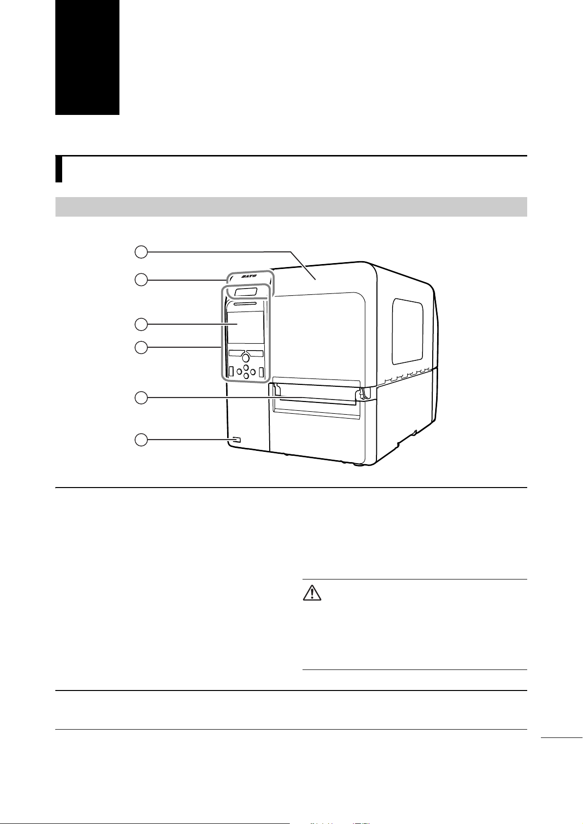
Top cover
w
NFC antenna location
*This feature is supported on printers from
serial number 6B~ and above.
e
Color LCD
r
Operator panel
t
Media discharge outlet
y
USB connector (Type A)
Enable the storage of printer setting
information with USB memory and for
connecting other devices like a barcode
checker, barcode scanner or a keyboard.
CAUTION
Be sure to perform a virus check for the USB
memory before connecting it to the printer. SATO
Corporation shall not be held responsible for any
printer malfunctions caused by a virus spread via
USB memory.
Parts Identification
1.1
1.1.1
Parts Identification of the Printer
Front View
Note
The pictures in this manual show the CL4NX unless otherwise stated.
CL4NX/CL6NX Operator Manual
15
Page 18
1 Parts Identification
14
9
10
7
8
11
12
13
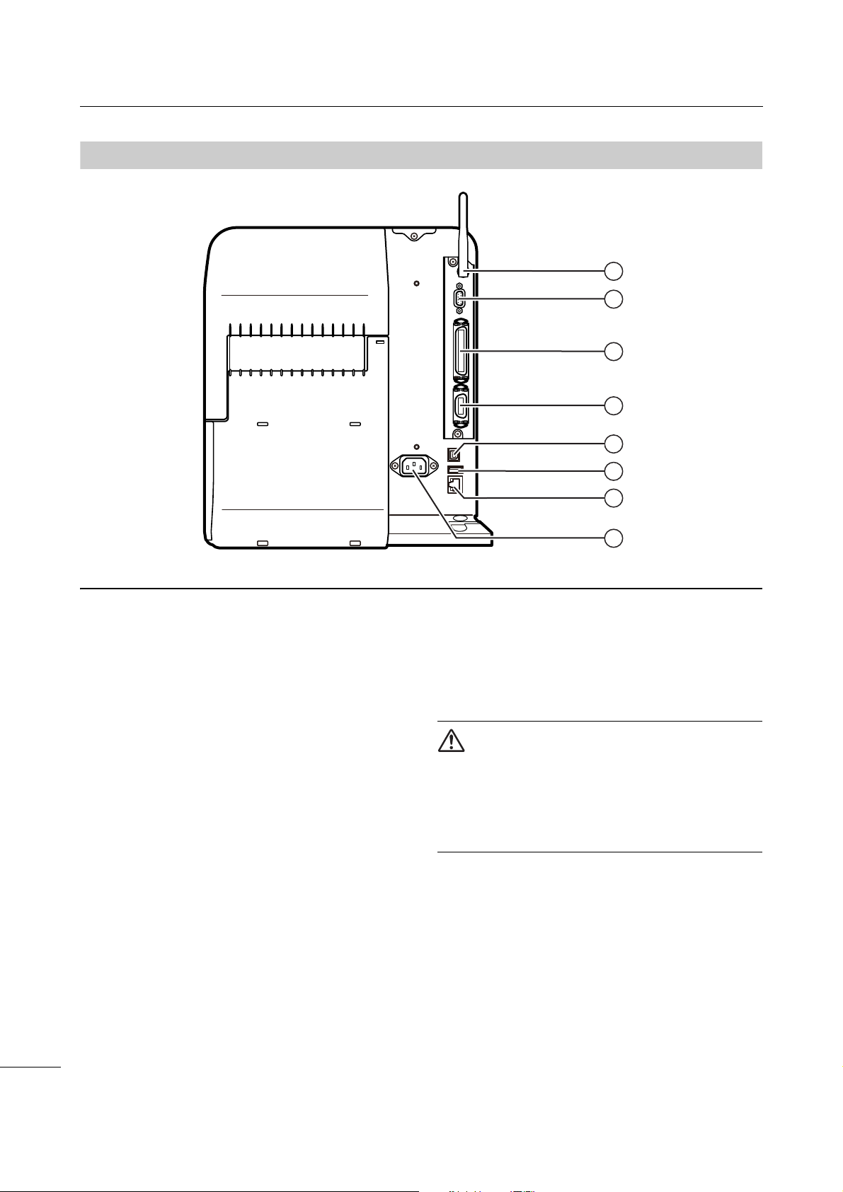
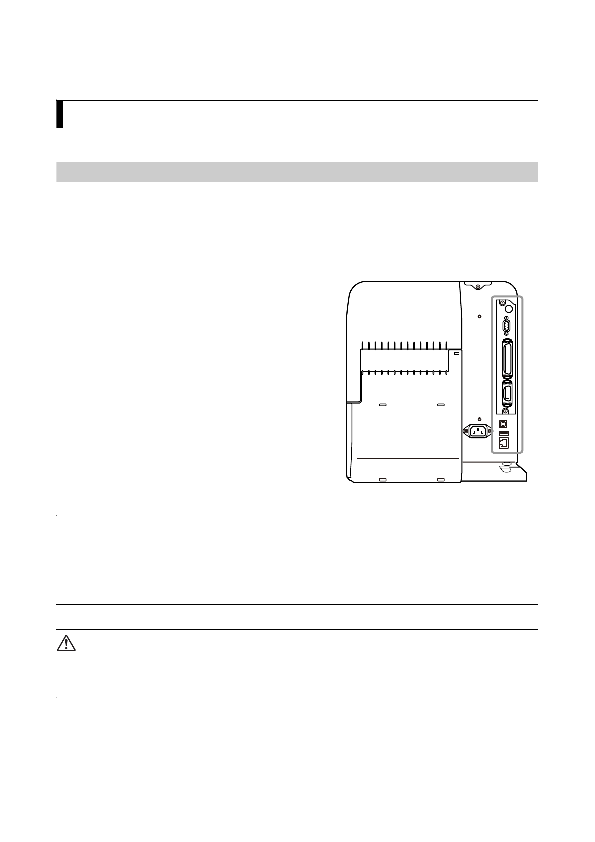
u
Wireless LAN antenna (optional)
Connector for installation of optional wireless
LAN antenna.
i
RS-232C connector
To connect the printer to the computer using
the RS-232C serial interface.
You can also connect a barcode checker.
Usage of the RS-232C interface can be
selected in the Interface > RS-232C >
Interface menu.
o
IEEE1284 connector
To connect the printer to the computer using
the IEEE1284 interface.
a
EXT connector (External signal
interface)
Interface connector for external signals.
Connect an optional device to this terminal.
s
USB connector (Type B)
To connect the printer to the computer using
the USB interface.
d
USB connector (Type A)
Enable the storage of printer setting
information with USB memory and for
connecting other devices like a barcode
checker, barcode scanner or a keyboard.
CAUTION
Be sure to perform a virus check for the USB
memory before connecting it to the printer. SATO
Corporation shall not be held responsible for any
printer malfunctions caused by a virus spread via
USB memory.
f
LAN connector
To connect printer to the network using the
LAN interface.
g
AC input terminal
Supplies power to the printer through the
inserted power cord.
Before connecting, make sure that the AC
voltage of your region is in the range of AC 100
to 240 V, 50 to 60 Hz.
1.1.2
Rear View
CL4NX/CL6NX Operator Manual
16
Page 19
1 Parts Identification
15
18
20
16
19
24
23
21
22
17
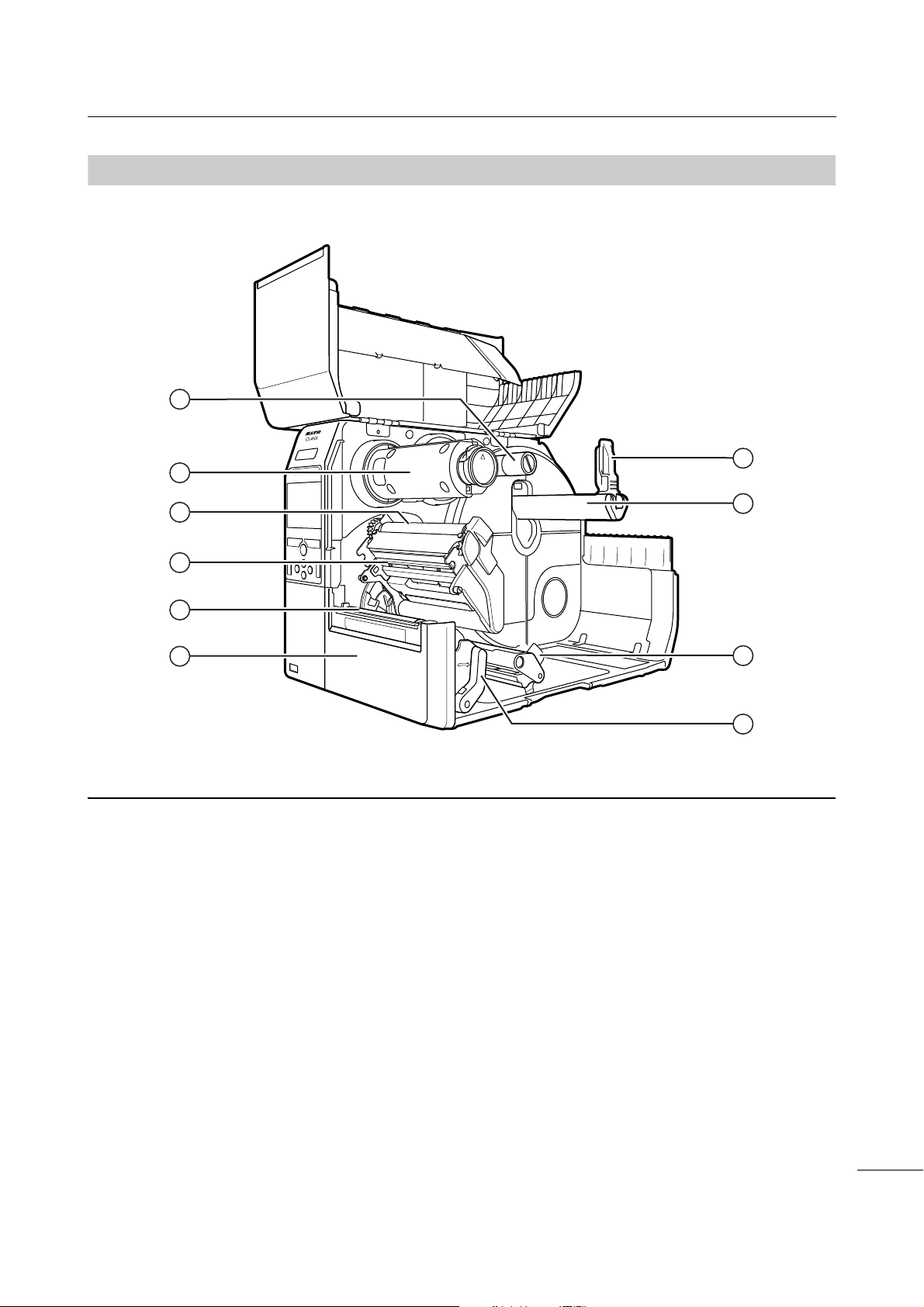
h
Ribbon supply spindle
j
Ribbon rewind spindle
k
Ribbon roller
l
Print head (Consumables)
Creates an image directly on the media or by
using a ribbon. Highest print quality is achieved
when regular maintenance is performed.
;
Platen roller (Consumables)
2)
Front cover
2!
Media holder guide
Used to hold the media roll.
2@
Media roll holder
Hang the media roll to the bar.
2#
Media guide
2$
Head lock lever
Used to release the print head assembly.
1.1.3
Internal View
CL4NX/CL6NX Operator Manual
17
Page 20
1 Parts Identification
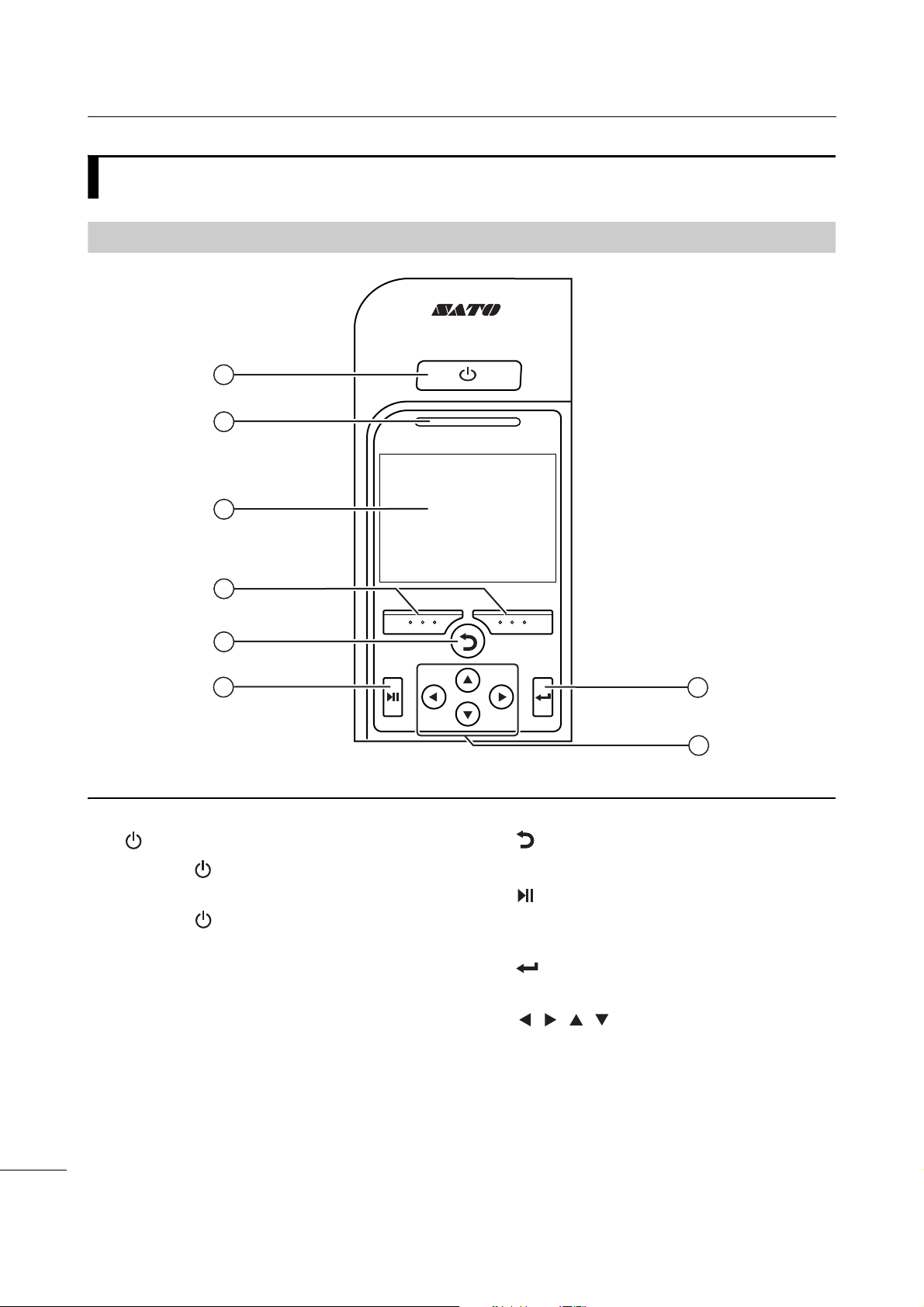
1
5
2
3
6
7
8
4
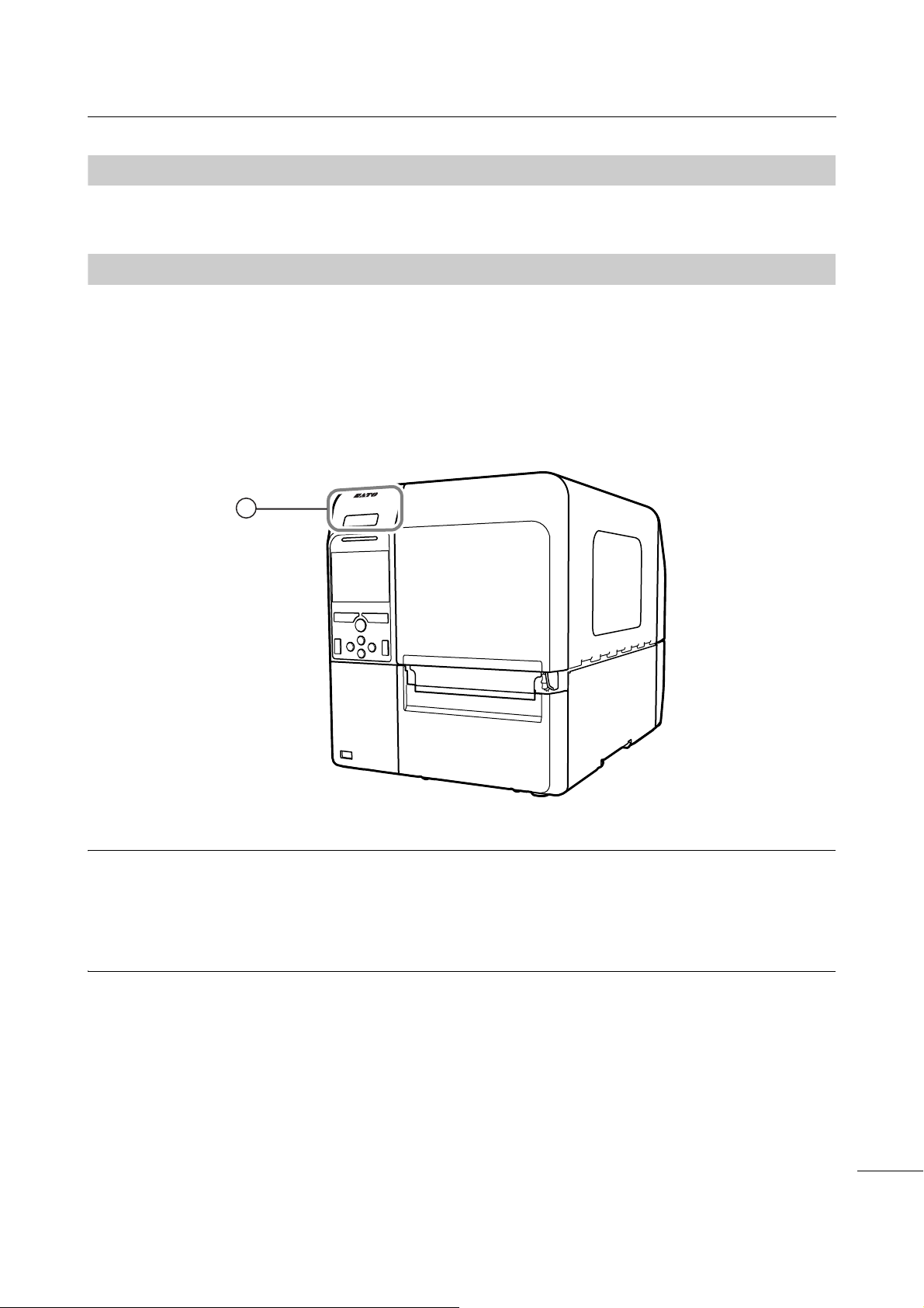
q
Power button
Press the power button until the LED lights
up in blue to power on the printer.
Press the power button for more than two
seconds to power off the printer.
w
LED indicator
e
Color LCD
r
Soft buttons
The functions change depending on the
screen. The functions of the buttons are
indicated on the bottom of the screen.
(For example, when in offline mode, left soft
button: ONLINE; right soft button: FEED)
t
Back button
Returns to the previous screen.
y
Line button
Toggle between online/offline mode or
playback/pause the video.
u
Enter button
Confirm the selected item or setting value.
i
/ / / Arrow buttons
Navigate the selection in the screen menu.
1.2
1.2.1
Parts on the Operator Panel
Operator Panel
18
CL4NX/CL6NX Operator Manual
Page 21
1 Parts Identification
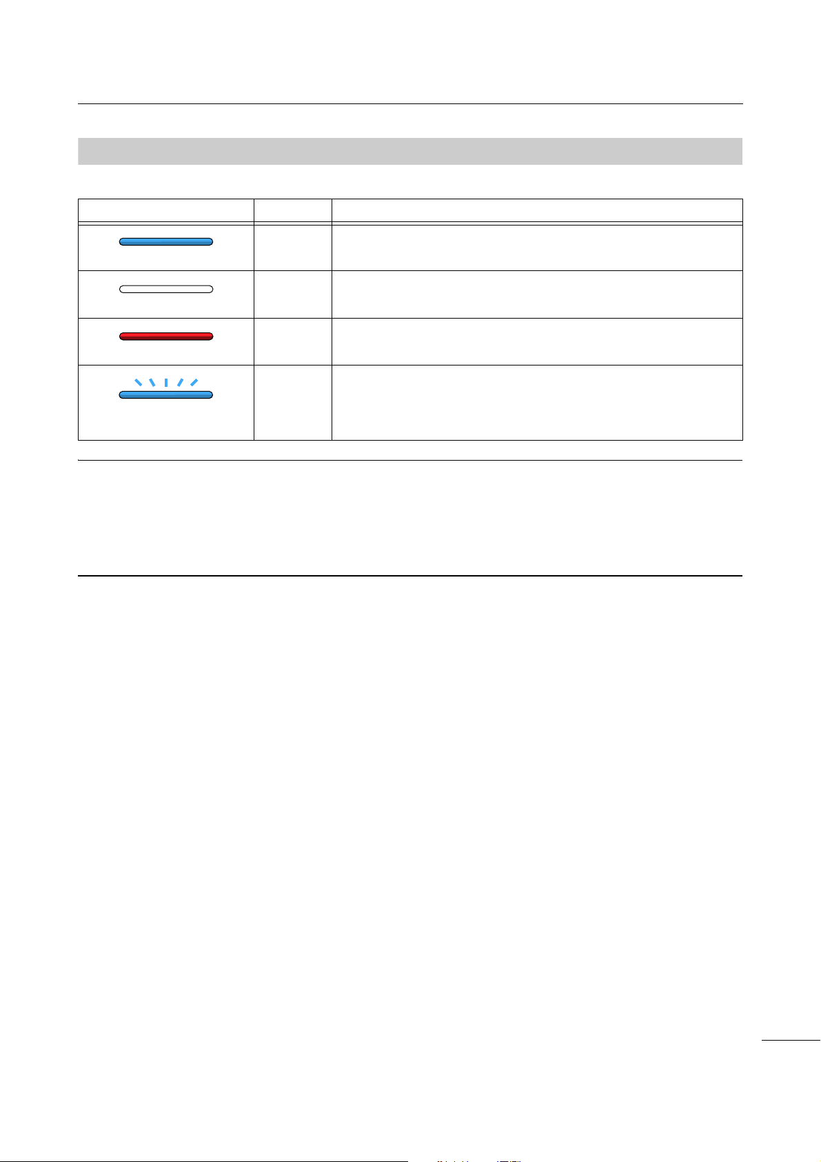
1.2.2
Flashes at intervals of two
seconds.
LED Indicator
LED Indicator Color Description
Blue Online mode
(Light off) Power off or offline mode
Red Printer error (For example, when the ribbon runs out)
Blue Sleep mode (energy saving mode)
Note
• If the printer enters sleep mode during a printer error status (LED lights red), the LED indicator will flash blue
at intervals of two seconds.
• By default, the printer goes into sleep mode after 60 minutes of inactivity. Refer to Section 4.4.5 System
Menu to change the period before the printer enters sleep mode.
CL4NX/CL6NX Operator Manual
19
Page 22

1 Parts Identification
This page is intentionally left blank.
CL4NX/CL6NX Operator Manual
20
Page 23

2
Installing the Printer
2.1
Install this printer in a location as follows:
• A location that is horizontal and stable.
• A location that has sufficient space for operating the printer.
Do not install this printer in a location as follows. Doing so could cause the printer to malfunction.
• A location that is subject to vibration.
• A location with high temperature and humidity.
• A dusty location.
• A location exposed to direct sunlight.
• A location with a lot of electrical noise.
• A location with a large fluctuation in power.
• A location with an explosive atmosphere (flammable gas or vapor).
Installation Precautions
CL4NX/CL6NX Operator Manual
21
Page 24

2 Installing the Printer
737 mm (29”)
271 mm
(10.7”)
83
mm
(3.3”)
83
mm
(3.3”)
150 mm
(5.9”)
150 mm
(5.9”)
729 mm (28.7”)
321 mm (12.6”)
150 mm
(5.9”)
258 mm (10.2”)
579 mm (22.8”)
Standard model
111 mm
(4.4”)
853 mm (33.6”)
337.5 mm
(13.3”)
150 mm
(5.9”)
778 mm (30.6”)
321 mm (12.6”)
150 mm
(5.9”)
307 mm (12.1”)
628 mm (24.7”)
Standard model
150 mm
(5.9”)
150 mm
(5.9”)
65.5
mm
(2.6”)
111 mm
(4.4”)
2.2
Installation Space
Make sure that there is sufficient space around the printer so that the top cover can be fully opened
when operating or cleaning the printer, or replacing consumables.
2.2.1
Front View (CL4NX)
2.2.2
Front View (CL6NX)
CL4NX/CL6NX Operator Manual
22
Page 25
2 Installing the Printer
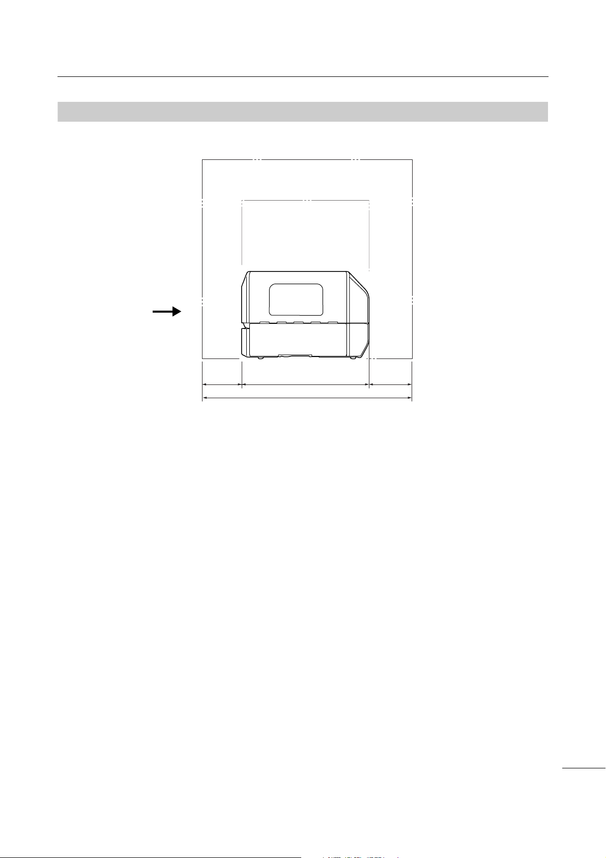
757 mm (29.8”)
457 mm
(18.0”)
150 mm
(5.9”)
150 mm
(5.9”)
Printer front view
2.2.3
Side View (CL4NX/CL6NX)
Make sure that there is sufficient space on the rear side of the printer so that no stress is applied to the
power cord or cables connected to the printer.
CL4NX/CL6NX Operator Manual
23
Page 26
2 Installing the Printer
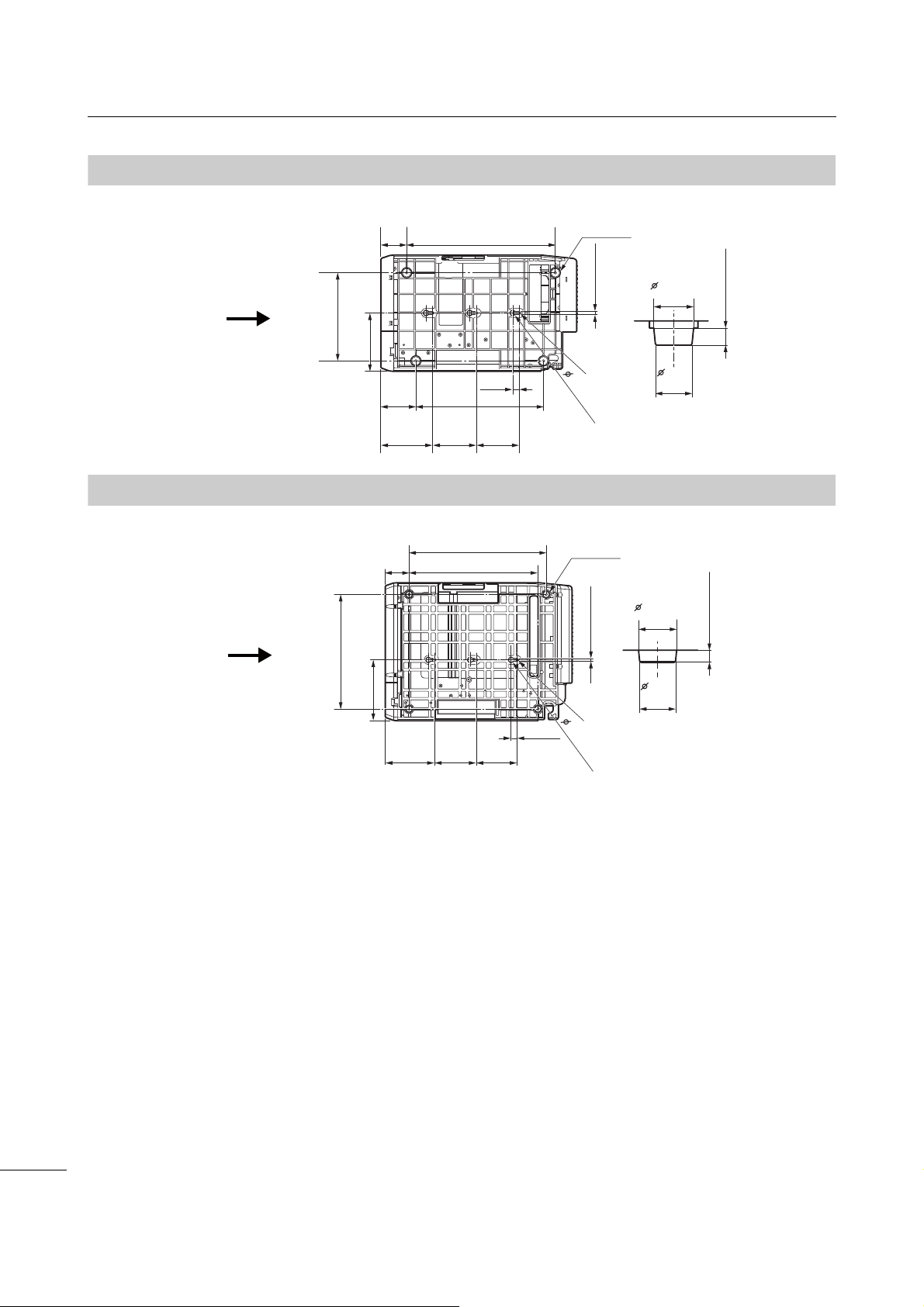
135.9 mm
(5.4”)
6 mm (0.2”)
120.4 mm
(4.7”)
102 mm
(4.0”)
100 mm
(3.9”)
15 mm (0.6”)
R3
13 mm (0.5”)
60 mm
(2.4”)
346.4 mm (13.6”)
205.6 mm
(8.1”)
297.5 mm
(11.7”)
81.5 mm
(3.2”)
8.5 mm (0.3”)
19.7 mm
(0.8”)
18 mm
(0.7”)
Rubber foot
Printer front view
6.2 mm (0.2”)
19.2 mm
(0.8”)
18 mm
(0.7”)
148.5 mm
(5.8”)
6 mm (0.2”)
120.4 mm
(4.7”)
102 mm
(4.0”)
100 mm
(3.9”)
15 mm (0.6”)
R3
13 mm
58.4 mm
(2.3”)
315 mm (12.4”)
280 mm (11.0”)
Rubber foot
2.2.4
2.2.5
Bottom View (CL4NX)
Bottom View (CL6NX)
335 mm (13.1”)
Printer front view
(0.5”)
24
CL4NX/CL6NX Operator Manual
Page 27
2 Installing the Printer
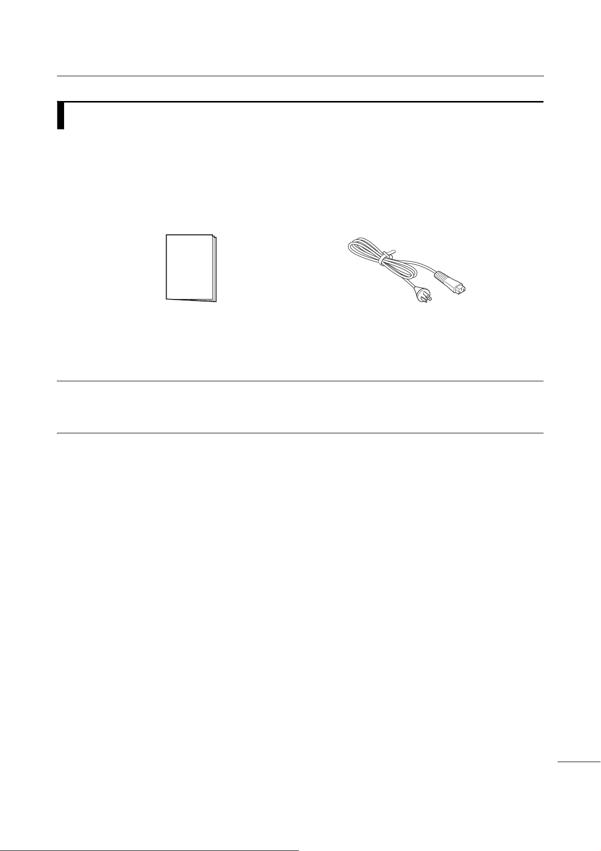
User documents
(Quick guide, Warranty, etc.)
AC power cord*
* The shape of power plug varies depending on the region in which it was purchased.
2.3
After unpacking the printer, make sure that you have all the bundled accessories: if there are any
missing items, contact the SATO reseller where you purchased the printer.
Checking the Bundled Accessories
Note
Keep the packaging box and cushioning material after installing the printer. You can pack the printer with this
packaging box for shipment when requesting for repairs.
CL4NX/CL6NX Operator Manual
25
Page 28
2 Installing the Printer
2.4
The connection of the interface cable is explained as follows:
2.4.1
This printer supports the following interfaces.
A printer connected with multiple interface cables can continue to operate when receiving data.
However, you cannot receive data from more than one interface at a time. Normally, do not use multiple
interfaces at a time.
The printer prints the received data in the reception order. The next received data is stored in the receive
buffer while the first data is printed.
• NFC (front side)
*This feature is supported on printers from serial
number 6B~ and above.
•USB
•LAN
• Bluetooth
• RS-232C
• IEEE1284
• External signal (EXT)
• Wireless LAN
Connecting the Interface Cable
Available Interfaces
Note
• The wireless LAN interface is optional.
• The NFC interface supports the handover function that simplifies the Bluetooth/Wi-Fi connection setup with
Android devices. For details, refer to Section 2.4.3 NFC Interface Connection.
In addition, the NFC interface can be used for changing printer settings with an Android device while the
printer is powered off and the power cord is not connected.
CAUTION
Do not connect or disconnect the interface cables (or use a switch box) with power supplied to either the
printer or computer. This may cause damage to the interface circuitry in the printer or computer and is not
covered by warranty.
CL4NX/CL6NX Operator Manual
26
Page 29
2 Installing the Printer
1
2.4.2
You can set the various interface settings of the printer through Interface in the Settings menu. For
details, refer to Interface in chapter 4 Operation and Configuration.
2.4.3
The NFC interface of the printer supports a handover function that simplifies the Bluetooth/Wi-Fi
connection setup with Android devices.
The handover function only performs the connection setup, such as the pairing and authentication with
NFC, and passes the actual interface to the more advanced Bluetooth and Wi-Fi when communicating
between NFC supported devices. In general, the pairing and authentication require some procedures to
enter authentication information, but the connection can be completed simply by holding the Android
devices over the printer while using NFC.
Touch the NFC antenna
Interface Settings
NFC Interface Connection
q of the printer with the NFC mark on the Android device.
Note
• This feature is supported on printers from serial number 6B~ and above.
• If it does not communicate well, shift the Android device to the front, back, left and right, and then hold it up
again.
• For the operation of the NFC for the Android device, refer to the user manual for the Android device.
CL4NX/CL6NX Operator Manual
27
Page 30
2 Installing the Printer
1
*
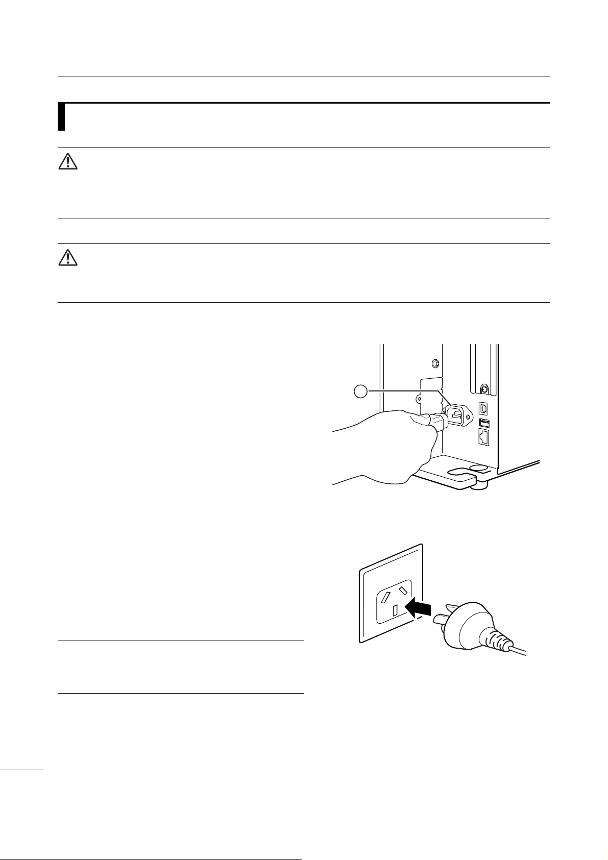
2.5
WARNING
• Do not touch the power button, connect or disconnect the power cord while your hands are wet. Doing so
could cause an electric shock.
• Always connect the ground wire to a ground terminal. Electric shock could occur if you do not.
CAUTION
• The attached power cord is designed exclusively for this printer.
• Do not use the attached power cord with other devices.
Connecting the Power Cord
1 Connect the power cord to the AC input
terminal q at the rear of the printer.
Take note of the orientation of the connector.
Secure the printer with one hand, and insert the
connector tightly.
2 Insert the power plug into an AC outlet.
Make sure that the AC voltage of your region is in
the range of AC 100 - 240 V, 50 - 60 Hz. If your
local voltage is not in the stated range, contact
your SATO reseller or technical support center.
*The shape of the power plug varies depending
on the region in which it was purchased.
Note
This product is also designed for IT power distribution
system with phase-to-phase voltage 230 V.
CL4NX/CL6NX Operator Manual
28
Page 31

2 Installing the Printer
2.6
WARNING
Do not touch the power button, connect or disconnect the power cord while your hands are wet. Doing so
could cause an electric shock.
CAUTION
An incorrect power on/off operation may damage the printer settings. In such a case, the printer settings are
reset to their default values. It is always recommended to use the power button to allow proper shutdown of
the printer and ensure changes made to menu settings are saved appropriately.
Note
You can power on/off the printer from the main power source by enabling Start on AC under the System
menu.
2.6.1
Power On/Off the Printer
Power On the Printer
1 Press the power button on the
operator panel until the LED lights up in
blue to power on the printer.
2 Online shows on the screen.
CL4NX/CL6NX Operator Manual
29
Page 32

2 Installing the Printer
2.6.2
• Do not power off the printer during operation, such as when printing or updating. Doing so could cause a
malfunction of the printer.
• Do not disconnect the power cord until the powering off process is completed on the printer.
Power Off the Printer
CAUTION
1 Make sure that the printer is in offline
mode before you power off.
If Online shows on the screen, press the
button to change to offline mode.
2 Press the power button for more
than two seconds to power off the
printer.
CL4NX/CL6NX Operator Manual
30
Page 33

2 Installing the Printer
2.7
When you power on the printer for the first time after purchase, the display shows the startup guide. The
startup guide is a function to help you through the initial printer configuration, such as setting date and
time, and loading the ribbon and media.
You can cancel the startup guide and perform the configuration later from the menu.
*If you have installed the optional RTC (Real Time Clock) kit, the time zone, date and time setting
screens show.
2.7.1
The startup screen shows when you first power on
the printer.
Starting Up the Printer (Startup Guide)
Startup Screen
2.7.2
Select the display language.
Select the language name using the /
buttons, then press the right soft button or
button to confirm.
Language Selection
CL4NX/CL6NX Operator Manual
31
Page 34

2 Installing the Printer
2.7.3
Set the region (time zone).
Select the region using the / buttons, then
press the right soft button or button to confirm.
2.7.4
Set the city (time zone).
Select the city using the / buttons, then press
the right soft button or button to confirm.
Region Setting with Optional RTC
City Setting with Optional RTC
2.7.5
Set the date.
Select the current value using the / buttons,
and move the cursor using the / buttons.
When you have completed the date setting, press
the right soft button or button to confirm.
Date Setting with Optional RTC
CL4NX/CL6NX Operator Manual
32
Page 35

2 Installing the Printer
2.7.6
Set the time.
Select the current value using the / buttons,
and move the cursor using the / buttons.
When you have completed the time setting, press
the right soft button or button to confirm.
Time Setting with Optional RTC
Note
The time is set in 24-hour format.
2.7.7
Set whether to use the ribbon or direct thermal
media to print.
The options are as follows:
• Use Ribbon: Print with a ribbon.
• Direct Thermal: Print using direct thermal
media.
Select the print method using the / buttons,
then press the right soft button or button to
confirm.
Print Method Setting
CL4NX/CL6NX Operator Manual
33
Page 36

2 Installing the Printer
2.7.8
Load the ribbon.
*Shows if you have selected Use Ribbon in the print
method setting.
You can check the setting method of the ribbon
through the video. Press the button to watch the
video.
Press the button to stop the video and return to
the previous screen.
After you complete the ribbon setting, press the right
soft button to go to the next screen.
Ribbon Setting
2.7.9
Set the type of sensor for sensing the media.
The available options will vary depending on the
default print mode of your printer.
The options are as follows:
• None: Disable the media sensor.
• Gap: Use the transmissive type sensor.
• I-Mark: Use the reflective type sensor.
Select the media sensor type using the /
buttons, then press the right soft button or
button to confirm.
Setting the Media Sensor Type
CL4NX/CL6NX Operator Manual
34
Page 37

2 Installing the Printer
2.7.10
Load the media.
You can check the setting method of the media
through the video.
Press the button to select video mode.
Media Setting
Note (for CL4NX only)
When you are using the linerless model, the video is
shown immediately after the button is pressed.
The selection screen of the video for playback
shows. (Not available for linerless model of
CL4NX.)
Select the video to playback using the /
buttons, then press the right soft button or
button to playback the video.
The options are as follows:
The options vary depending on the printer model.
Standard Model and Cutter Model
• Roll: Shows the video on how to load the media
roll.
• Fanfold: Shows the video on how to load the
fan-fold media.
Dispenser Model
• Dispenser: Shows the video on how to eject the
liner out of the printer.
• Rewinder: Shows the video on how to rewind
the liner in the printer.
Press the button to stop the video and return to
the previous screen.
After you complete the media setting, press the
right soft button to go to the next screen.
CL4NX/CL6NX Operator Manual
35
Page 38

2 Installing the Printer
2.7.11
This screen shows when the startup guide
completes.
If you want the startup guide to show the next time
you start up, press the left soft button. If not, press
the right soft button.
When you press one of the soft buttons, the printer
automatically feeds the media (to the print head
position) and enters online mode.
Confirmation Screen
Note
You can enable or disable the startup guide in Startup Guide under the Tools menu.
2.7.12
You can cancel the startup guide at any time.
When you press the left soft button on the setting
screen, the screen to the right shows.
Select whether or not to show the startup guide
during the next startup using the / buttons,
and press the right soft button to confirm.
To cancel and return to the startup guide setting,
press the left soft button.
Startup Guide Cancelation
Note
• You can enable or disable the startup guide in Startup Guide under the Tools menu.
• Even if you cancel the startup guide during play, the printer will save the settings you have changed.
CL4NX/CL6NX Operator Manual
36
Page 39

+
The ink is coated
on the inner side.
(Face-in ribbon)
The ink is coated
on the outer side.
(Face-out ribbon)
Loading the Ribbon and
3
This printer supports two types of print methods, thermal transfer and direct thermal. Thermal transfer
printing transfers the ink of the ribbon to the media. Direct thermal printing creates the image on direct
thermal media. Ribbon is not necessary if you are using direct thermal media.
3.1
There are two wind directions for the ribbon. Face-out means the ink is on the outer side and Face-in
means the ink is on the inner side. This printer supports both wind directions. You can examine the ink
side of the ribbon using the following procedure:
Media
Checking the Ink Side of the Ribbon
1 Place the outer side of the ribbon onto
the media (touching).
2 Scratch the inner side of the ribbon with
your fingernail or a pointed object.
3 If there is a mark on the media, the ink is
coated on the outer side of the ribbon.
CL4NX/CL6NX Operator Manual
37
Page 40

3 Loading the Ribbon and Media
Face-in ribbon
Face-out ribbon
1
3.2
Use genuine SATO media and ribbons for the printer, for optimum print quality.
CAUTION
• The print head and its surroundings are hot after printing. Be careful not to touch it, to avoid being burned.
• Touching the edge of the print head with your bare hand could cause injury.
The routing path of the ribbon is shown in the right
picture.
Loading the Ribbon
Note
You can also refer to the sticker located on the inner side of the top cover.
1 Open the top cover q.
CAUTION
Open the top cover fully to prevent accidental drop of
the cover.
CL4NX/CL6NX Operator Manual
38
Page 41

2 Push the ribbon rewind spindle w all the
2
3
5
4
way in.
If there is any ribbon on the ribbon rewind spindle,
remove it from the spindle before installing new
ribbon.
3 Push the head lock lever e towards the
rear.
3 Loading the Ribbon and Media
4 Load the ribbon r onto the ribbon supply
spindle t.
While taking note of the wind direction, insert the
ribbon all the way in.
CL4NX/CL6NX Operator Manual
39
Page 42

3 Loading the Ribbon and Media
6
5
7
2
7
2
5 From the ribbon supply spindle t, pass
the ribbon below the print head y.
6 Wind the ribbon counterclockwise to the
ribbon rewind spindle w and grip sheet
u.
Turn the ribbon rewind spindle counterclockwise for
several rounds, to wind the ribbon.
7 If the media is already loaded, press the
print head down until the head lock lever
is locked.
If the media is not loaded, continue with Section 3.5
Loading Media.
8 Close the top cover.
CL4NX/CL6NX Operator Manual
40
Page 43

3 Loading the Ribbon and Media
1
3.3
Removing the Ribbon
1 Press the tab q on the tip of the ribbon
rewind spindle to pull it out.
2 Pull to remove the used ribbon from the
ribbon rewind spindle.
3 Push the ribbon rewind spindle all the
way in.
CL4NX/CL6NX Operator Manual
41
Page 44

3 Loading the Ribbon and Media
14 mm
(0.55”)
1.5 mm (0.06”)
I- m a r k journal paper/
linerless label (CL4NX only)
Gap labelI-mark label
3 mm (0.12”)
3 mm
(0.12”)
3 mm
(0.12”)
1.5 mm (0.06”)
14 mm
(0.55”)
3 mm
(0.12”)
Media feed
direction
Media feed
direction
Media feed
direction
3.4
Usable Media
This printer can print on two types of media; media roll and fan-fold media. The printer uses media
sensors to detect I-marks or Gaps on the media in order to precisely print the content.
3.4.1
Adjusting the Position of the Media Sensor
When you use nonstandard media (for example, media with printing on the underside, or media with a
special shape), the media sensor cannot sense the I-mark or Gap of the media correctly. In such a case,
adjust the position of the media sensor to sense the I-mark or Gap correctly.
Adjust the media sensor guide to the position where it
can sense the I-mark or Gap of the media.
The I-mark sensor is below the mark, and the Gap
sensor is below the mark.
42
CL4NX/CL6NX Operator Manual
Page 45

3 Loading the Ribbon and Media
Face-in media
Face-out media
3.5
Use genuine SATO media and ribbons for the printer, for optimum print quality.
CAUTION
• The print head and its surroundings are hot after printing. Be careful not to touch it, to avoid being burned.
• Touching the edge of the print head with your bare hand could cause injury.
3.5.1
The routing path of the media is shown in the right
picture.
When loading the media, make sure that the print side
is facing up.
Loading Media
Loading Media Roll
1 Open the top cover.
CAUTION
Open the top cover fully to prevent accidental drop of
the cover.
2 Push the head lock lever towards the
rear to unlock the print head.
CL4NX/CL6NX Operator Manual
43
Page 46

3 Loading the Ribbon and Media
2
1
3
4
1
5
6
3 Pull the media holder guide q and media
guide w away from the printer.
Turn the knob e counterclockwise to release the
media guide.
4 Load the media in the media holder r.
Make sure that the media roll is all the way
in to inside of the printer.
5 Push the media holder guide q lightly
against the media roll.
6 Pass the media below the media damper
t and media sensor guide y while
pushing the media to inside of the printer.
Make sure that the end of the media extends out the
front of the printer.
CL4NX/CL6NX Operator Manual
44
Page 47

7 Press the print head down until the head
2
3
Load the media from the
rear of the printer.
Load the media from the
bottom of the printer.
lock lever is locked.
8 Press the media guide w lightly against the
end of the media, then turn the knob e to
lock the media guide.
9 Close the top cover.
10
After loading the media and ribbon, perform
a test print to make sure that the media is
loaded correctly.
Refer to the Test Print menu in Section 4.4.6 Tools
Menu for details on how to perform a test print.
3 Loading the Ribbon and Media
CAUTION
When closing the top cover, be careful not to pinch your fingers.
3.5.2
Place the fan-fold media on a flat location, then load the media from the media slot on the rear or the
bottom of the printer.
The routing path of the media is shown in
the right picture.
When loading the media, make sure that
the print side faces up.
After passing the media through the slot,
refer to steps 5 through 10 of
3.5.1 Loading Media Roll
media.
Loading Fan-fold Media
Section
to load the
Note
If a media jam frequently occurs with the media being loaded from the bottom of the printer, change the load
location to the rear of the printer.
CL4NX/CL6NX Operator Manual
45
Page 48

3 Loading the Ribbon and Media
1
1
2
1
2
3.5.3
Refer to the procedure in Section 3.5.1 Loading Media Roll or Section 3.5.2 Loading Fan-fold Media to
load the media.
For models with a cutter installed, pull the tab
the cutter unit in the direction shown, then open up
the cutter-open lever before passing the media
through it.
After loading media, close the cutter-open lever and
then push the tab
Loading Media with the Optional Cutter
q of
q in the reverse direction to lock it.
CAUTION
Be careful not to touch the cutter blade.
3.5.4
Loading Media with an Optional Dispenser and Liner Discharge Outlet
This section describes the procedure to dispense the
label and eject the liner out of the printer.
1 Refer to steps 1 through 6 of Section
3.5.1 Loading Media Roll to load the
media.
2 Press the tab q at the front of the printer to
open the dispenser unit w.
CL4NX/CL6NX Operator Manual
46
Page 49

3 Remove about 30 cm (11.8”) of labels e
4
5
3
4
Label
Liner
from the liner r, then pass the liner r
through the gap of the dispenser unit to the
outside of the printer.
4 Adjust the dispenser roller t to the center
of the label.
5 Close the dispenser unit.
6 Close the print head and top cover.
3 Loading the Ribbon and Media
3.5.5
This section describes the procedure to dispense the label and rewind the liner in the printer.
Note
The maximum diameter of the liner that can be rewound in the printer is 120 mm (4.72”).
The routing path of the media is shown in the right
picture.
Loading Media with an Optional Dispenser and Liner Rewinder
CL4NX/CL6NX Operator Manual
47
Page 50

3 Loading the Ribbon and Media
1
2
4
5
3
4
7
4
6
1 Refer to steps 1 through 7 of Section
3.5.1 Loading Media Roll to load the
media.
2 Press the tab q at the front of the printer to
open the dispenser unit w.
3 Remove about 80 cm (31.5”) of labels e
from the liner r, then pass the liner r
through the gap of the dispenser unit to
the inside of the printer.
4 Adjust the dispenser roller t to the center
of the label.
5 Pass the liner r below the liner rewinder
y, then attach it with the clip u.
6 Rotate the liner rewinder y
counterclockwise by hand, to wind the liner.
7 Close the dispenser unit.
8 Close the print head and top cover.
CL4NX/CL6NX Operator Manual
48
Page 51

3 Loading the Ribbon and Media
2
1
3.5.6
Removing the Liner from the Rewinder
1 Pull the clip q away from the printer then
pull to remove the liner w.
2 Place the clip back to its original position.
Note
The rewinder can take up maximum a diameter of 120
mm (4.72”) of liner.
CL4NX/CL6NX Operator Manual
49
Page 52

3 Loading the Ribbon and Media
This page is intentionally left blank.
CL4NX/CL6NX Operator Manual
50
Page 53

Change to
offline mode.
Change to
online mode.
Show the adjustments mode
when the print job is paused.
Show the settings mode
when there are no print jobs.
Cancel the print job.
Feed the media.
Operation and
4
The display of the printer varies depending on the following modes:
• Online mode: refer to Section 4.1.1 Online Mode/Offline Mode.
• Offline mode: refer to Section 4.1.1 Online Mode/Offline Mode.
• Error display: refer to Section 4.1.3 Error Icon.
• Settings mode: refer to Section 4.2 Settings Mode.
4.1
4.1.1
In online mode, you can execute the print job.
Configuration
Display and Operation
Online Mode/Offline Mode
In offline mode, the print job will stop.
You can adjust the print settings, cancel the print job or feed the media.
After you complete or cancel the print job, you can show the settings mode.
CL4NX/CL6NX Operator Manual
51
Page 54

4 Operation and Configuration
Status Bar
4.1.2
The icons on the status bar of the display show the printer status.
• Communication Interface Status
Status Icon
Icon Description
Bluetooth is enabled but not connected.
Bluetooth is enabled and connected.
Network link is enabled but not connected.
Network link is enabled and connected.
NFC is enabled but not connected.
NFC is enabled and connected.
Not connected to the NTP time server.
Wi-Fi is not connected.
Wi-Fi is connected.
Signal Level: 1
Wi-Fi is connected.
Signal Level: 2
CL4NX/CL6NX Operator Manual
52
Page 55

Icon Description
Wi-Fi is connected.
Signal Level: 3
Wi-Fi is connected.
Signal Level: 4
Wi-Fi Direct is not connected.
Wi-Fi Direct is connected.
Signal Level: 1
Wi-Fi Direct is connected.
Signal Level: 2
Wi-Fi Direct is connected.
Signal Level: 3
4 Operation and Configuration
Wi-Fi Direct is connected or the printer is set to act as an access point.
Signal Level: 4
Printer is connected to USB host.
Waiting for external input/output signal.
RFID mode is enabled (CL4NX only).
Standard code is disabled (Non-standard code).
• USB Memory Status
Icon Description
USB memory is connected.
• Barcode Checker Status
Icon Description
Barcode checker is connected.
CL4NX/CL6NX Operator Manual
53
Page 56

4 Operation and Configuration
?
• Barcode Scanner Status
Icon Description
Barcode scanner is connected in AEP mode.
• Print Job Status
Icon Description
Waiting for media removal. Remove the media.
Ribbon is near the end. Prepare a new ribbon.
Label is near the end. Prepare new media.
Command error detected. Check the print data.
Receive buffer is nearly full. Wait until the printer starts printing the previously sent data,
and then send the next data.
Defective print head is detected. Replace the print head.
Incompatible print head is detected. Replace the print head.
• Maintenance Status
Icon Description
Clean the print head or platen roller.
Replace the print head.
Replace the platen roller.
CL4NX/CL6NX Operator Manual
54
Replace the cutter unit.
Page 57

4 Operation and Configuration
Change to offline mode if
allowed for the active
error.
Change to settings mode or
guidance video.
Clears the error if allowed
for the active error.
Feed the media if allowed for
the active error.
Selection area
Error Icon
Error number
4.1.3
When a printer error occurs, the error status shows on the screen with an icon.
When an error occurs, you can perform the following operations:
• Change to offline mode.
• Cancel the error.
• Feed the media.
• Change to settings mode.
• Change to guidance video.
Error Icon
Note
The available operations vary, depending on the situation.
• Error Icon
Icon Description
Paper end is detected.
Ribbon end is detected.
CL4NX/CL6NX Operator Manual
55
Page 58

4 Operation and Configuration
Icon Description
Print data is larger than the media size.
Sensor error is detected.
Print head is unlocked.
Print head error is detected.
• Communication error is detected.
• BCC error is detected.
• CRC error is detected.
Receive buffer overflow.
Cutter error is detected.
• USB memory is not accessible.
• There is no free space in the USB memory.
Calendar error is detected.
• Writing/reading information to/from the RFID tag failed (CL4NX only).
• With Non-RFID warning enabled and RFID tag loaded, the items received do not
contain an RFID issue command (CL4NX only).
• Wireless LAN setting error is detected.
• Authentication with the server failed.
• Authentication with the server timed out.
CL4NX/CL6NX Operator Manual
56
Page 59

Icon Description
Printer error is detected.
The temperature of the print head has exceeded the tolerance range.
RFID module is defective (CL4NX only).
Bluetooth module is defective.
4 Operation and Configuration
Paper jam is detected. (CL4NX only)
NFC error is detected.
NFC command error is detected.
The barcode checker is not detected at printer startup or at the start of printing when the
barcode check mode is enabled.
• The barcode could not be read.
• The read result of the barcode does not match the command data.
CL4NX/CL6NX Operator Manual
57
Page 60

4 Operation and Configuration
4.1.4
The printer contains the following guidance videos for visual reference of printer operations.
No.
1 Media roll loading (Standard) - Possible Possible
2 Media roll loading (Cutter) - Possible Possible
3 Media roll loading (Linerless) (CL4NX only) - Possible Possible
4 Media roll loading (Dispenser) - Possible Possible
5 Media roll loading (Dispenser with rewinder) - Possible Possible
6 Fan-fold media loading (Standard) - Possible Possible
7 Fan-fold media loading (Cutter) - Possible Possible
8 Ribbon loading - Possible Possible
9 Media roll replacement (Standard) Possible - Possible
10 Media roll replacement (Cutter) Possible - Possible
11 Media roll replacement (Linerless) (CL4NX only) Possible - Possible
Guidance Video
Guidance Video
Error
screen
Show video from
Startup
Guide
Information
menu
12 Media roll replacement (Dispenser) Possible - Possible
13 Media roll replacement (Dispenser with rewinder) Possible - Possible
14 Fan-fold media replacement (Standard) Possible - Possible
15 Fan-fold media replacement (Cutter) Possible - Possible
16 Ribbon replacement Possible - Possible
17 Print head replacement - - Possible
18 Platen roller replacement - - Possible
19 Cleaning - - Possible
You can play the guidance video using the following procedures:
• To play the guidance video from the error screen
1 On the error screen, press the button
to play the guidance video.
If there are more videos to choose from, press the
arrow buttons to select the guidance video, then
button.
press
The guidance video starts.
2 Follow the procedures to resolve the error
according to the guidance video.
CL4NX/CL6NX Operator Manual
58
Page 61

• To get access to the guidance video in online mode
1 Press the button in online mode.
The printer enters offline mode.
2 Press the button.
The printer enters settings mode.
4 Operation and Configuration
3 Select Information using the /
buttons.
4 Press the button.
The item list shows.
5 Select Help using the / buttons.
6 Press the button.
The list of guidance videos shows.
CL4NX/CL6NX Operator Manual
59
Page 62

4 Operation and Configuration
Rewind the video. Fast-forward the video.
Playback or pause
the video.
Stop the playback of
the video and return to
menu.
Playback the video
from the start.
Indication panel shows
again when one of the
buttons is pressed.
7 Select the video for playback using the
/ buttons, then press the button.
The guidance video starts.
The guidance video operating procedures are described below:
CL4NX/CL6NX Operator Manual
60
Page 63

4 Operation and Configuration
4.1.5
Follow the procedure below to adjust the print position, print darkness and print speed during printing.
Adjusting the Print Settings During Printing
1 Press the button to pause print job and
change the printer to offline mode.
2 Press the button.
The Adjustments menu shows.
3 Select an item and adjust the setting.
For details on how to adjust settings, refer to
Section 4.2 Settings Mode.
4 Press the button to return to offline mode.
5 Press the button to change to online mode.
The print job resumes with the adjusted settings.
Note
When Prioritize in the Printing > Advanced menu has been set to Commands and the print settings have
been specified by command, the changes made in the Adjustments menu will be applied only to the data
already analyzed at that time. The settings specified by command will be applied to the rest of the data.
CL4NX/CL6NX Operator Manual
61
Page 64

4 Operation and Configuration
4.1.6
Cancel the print job according to the following procedure. When the print job is canceled, the data stored
in the receive buffer of the printer is also deleted.
Canceling the Print Job
1 Press the button to change the printer to
offline mode.
2 Press the left soft button.
A message shows, confirming that you want to
cancel the print job.
3 Press the right soft button.
The print job will be canceled.
CL4NX/CL6NX Operator Manual
62
Page 65

4 Operation and Configuration
Tools InformationSystemApplicationsInterfacePrintingShortcut
4.2
In settings mode, the following menus show:
Shortcut Directly access frequently used settings.
Printing Access the settings related to printing.
Interface Access the settings related to the interfaces.
Applications Access the settings related to the printer's command language.
System Access the settings related to the display language, buzzer volume etc.
Tools Access the test print, initialization and other settings.
Information Access the printer information and guidance videos.
Settings Mode
Menu Description
4.2.1
The settings mode can be shown when no print jobs remain in the printer.
Change the printer to settings mode according to the following procedure:
Changing to Settings Mode
1 Press the button in online mode.
The printer enters offline mode.
CL4NX/CL6NX Operator Manual
63
Page 66

4 Operation and Configuration
2 Press the button.
The printer enters settings mode.
To exit the settings mode, press the button.
4.2.2
After entering the settings mode, you will be prompted
with password if password is enabled (Refer to
Password Enable in System > Password).
When you exit from the settings mode after a
successful login, LOG OUT shows on the bottom left
of the screen.
Press the left soft button if you want to log out
immediately.
Password is required to enter the settings mode
again.
Log In to/Log Out of the Settings Mode
Note
With password enabled, if no button is pressed for
about ten minutes after login, the login session will end
automatically. Password is required to enter the
settings mode again.
CL4NX/CL6NX Operator Manual
64
Page 67

4 Operation and Configuration
There are more items
in the next layer.
Returns to the previous
screen.
4.2.3
Select an item in settings mode according to the following procedure:
Item Selection
1 Select menu using the / buttons.
2 Press the button.
The item list shows.
3 Select an item using the / buttons.
4 Press the button.
If the selected item is a setting item, the setting
screen shows.
If the selected item is a command, the command will
be executed.
Items with a “>” indicated on the right side have more items in the next layer of the submenu.
Press the or button to show the next layer.
Similarly, select an item using the
Press the button to return to the previous screen.
/ and buttons.
CL4NX/CL6NX Operator Manual
65
Page 68

4 Operation and Configuration
Change the input mode.
Text box
Selection area
Save the character you enter
in the text box and return to
the item list.
Cancel the character you
enter in the text box and
return to the item list.
Enter the selected character
into the text box.
Delete the character to
the left of the cursor
indicated in the text box.
Select the character for input
using the arrow buttons. The
selected character will be
highlighted in the selection
area.
4.2.4
This section describes the character and number input on the setting screen and how to select an item
from the list.
Setting Value Input or Selection
Note
You can also input characters and numbers from a USB keyboard by connecting it to the printer.
• Character Input
CL4NX/CL6NX Operator Manual
66
Page 69

• Numeric Input
Change the input mode.
Text box
Selection area
Save the number you enter in
the text box and return to the
item list.
Cancel the number you enter
in the text box and return to
the item list.
Enter the selected number
into the text box.
Delete the number to the
left of the cursor indicated
in the text box.
Select the number for input
using the arrow buttons.
The selected number will be
highlighted in the selection
area.
Selection area
Save the selection from the
list and return to the item list.
Cancel the selection from the
list and return to the item list.
Select an item using the
/ buttons. The
selected item will be
highlighted in the selection
area.
4 Operation and Configuration
• Selection from the list
CL4NX/CL6NX Operator Manual
67
Page 70

4 Operation and Configuration
Selection box
Perform the function as
shown on the screen above.
Returns to the previous
screen.
Select an item using the
/ buttons. The selected
item will be highlighted in the
selection area.
Change the value in the
selection box using the
/ buttons.
Text box
Save the IP address you
enter in the text box and
return to the item list.
Cancel the IP address you
enter in the text box and
return to the item list.
Select the digit for input
using the / buttons.
Select the number to
input using the /
buttons.
• Selection from the box
• Entering an IP address
CL4NX/CL6NX Operator Manual
68
Page 71

4 Operation and Configuration
4.3
There are six main menus in Settings mode and each menu contains many layers of submenus.
Frequently used settings are also listed in the Shortcut menu so that you can directly access them.
The tables below outline the Settings menus tree structure. Refer to the tree structure to understand
where information is located in the setting menus. Click on the items in blue to link directly to the details
of the selected items.
Settings Menu Tree Structure
Shortcut
Adjustments
Speed
Darkness Range
Darkness
Auto-mode
Print Mode
Backfeed
Ribbon
Sensor Type
Head Check
Help
Shortcuts to frequently used settings
CL4NX/CL6NX Operator Manual
69
Page 72

4 Operation and Configuration
Printing Submenus
Label Length
Label Width
Auto Measure
Ribbon
Ribbon Near End
Speed
Sensor Type
Auto-mode
Print Mode
Backfeed
Eject Cut
Darkness Range
Darkness
Imaging Vertical
Horizontal
Advanced Calibrate Auto-calibration
Head Check
Head Check Mode
Every Page
Check Media Size
Adjustments Offset
Start Online
Feed After Error
Feed At Power On
Finisher Feed
Paper End
Head Base Position
Prioritize
Reprint
Print End Position
Label Near End
GAP Levels
GAP Slice Level
I-Mark Levels
I-Mark Slice Level
Pitch
Darkness Adjust
CL4NX/CL6NX Operator Manual
70
Page 73

Interface Submenus
Network Settings LAN IPv4 Mode
DHCP/Renew Lease
IP Address
Netmask
Gateway
DNS
IPv6 Mode
DHCP/Renew Lease
IP Address
Prefix Length
Gateway
DNS
Proxy Enabled
Server
Exclude
Wi-Fi IPv4 Mode
DHCP/Renew Lease
IP Address
Netmask
Gateway
DNS
IPv6 Mode
DHCP/Renew Lease
IP Address
Prefix Length
Gateway
DNS
Proxy Enabled
Server
Exclude
Wi-Fi
Protected
Setup
Wi-Fi Direct Device Name
SSID
Button (PBC)
PIN
Connect
Start Group
Remove Group
Disconnect
SSID
IP Address
Passphrase
4 Operation and Configuration
CL4NX/CL6NX Operator Manual
71
Page 74

4 Operation and Configuration
Interface Submenus
Network Settings Wi-Fi Hidden SSID
Services Ports Port1
Mode
Channel
Security
WEP Conf. Authentication
Key Index
Key #1 - Key #4
WPA Conf. WPA Authentication
PSK
EAP Conf.
EAP Conf. EAP Mode
Inner Method
Username
Password
Anon. Outer ID
Verify Server Cert.
Private Key P/W
PAC Auto Provisioning
PAC P / W
Interface
Port2
Port3
Flow Control
Multiple connections
Legacy Status for Port 9100
BCC
NTP Enable
Error
Time Server IP
LPD Enable
DNS Lookup
FTP Enable
FTP Timeout
CL4NX/CL6NX Operator Manual
72
Page 75

Interface Submenus
Network Services SNMP sysContact
sysName
sysLocation
prtMarkerCounterUnit
Agent Enable
Traps Enable
Advanced ARP
Announcement
Additional
Periodic
4 Operation and Configuration
Read-Only SNMP Version
Community
User
User Security
Authentication Protocol
Authentication
Passphrase
Privacy Protocol
Privacy Passphrase
Read-Write SNMP Version
Community
User
User Security
Authentication Protocol
Authentication
Passphrase
Privacy Protocol
Privacy Passphrase
SNMP Version
IP Version
Destinations
Destination 1
Destination 2
Destination 3
Community
User
Engine ID
Security
Authentication Protocol
Authentication Passphrase
Privacy Protocol
Privacy Passphrase
CL4NX/CL6NX Operator Manual
73
Page 76

4 Operation and Configuration
Interface Submenus
IEEE1284 Flow Control
BCC
RS-232C Interface
Baudrate
Parameters
Flow Control
BCC
USB Flow Control
BCC
Bluetooth Enable
Name
PIN Code
BD Address
Firm Version
Host BD Addr
Authentication
ISI
ISW
PSI
PSW
CRC Mode
Flow Control
NFC I/F Enable
Ignore CR/LF
Ignore CAN/DLE
External I/O Enable
Signals EXT 9PIN
EXT I/O Re-print
EXT Mode
Inputs Start Print
Reprint
Outputs Paper End
Ribbon End
Machine Error
Print Done
Qty/Offline
Ribbon Near End
Dispenser
Label Near End
CL4NX/CL6NX Operator Manual
74
Page 77

Interface Submenus
RFID (CL4NX
only)
Antenna Pitch
Write Power
Read Power
Tag O f f s et
Reader Model
Reader Version
View Memory Bank
Retry Mode
Retries
Mark bad tags
MCS MCS
Chip Manufacturer
Pre-Encoded Tag
Assign Prefix
MCS Prefix Digit
Input Prefix
Non-RFID Warning
Log RFID Data
Data To Record
Output Error Mode
Pulse Length
Counters Lifetime Count Success
Count Failure
Count Total
User Count Success
Count Failure
Count Total
4 Operation and Configuration
CL4NX/CL6NX Operator Manual
75
Page 78

4 Operation and Configuration
Applications Submenus
Protocol
SBPL Show Error
Standard Code
Orientation
Font Settings Zero Slash
Compatible M-8400 Compatibility
SZPL Label Shift
Caret
Delimiter
Tilde
Clock Format
SIPL Font Settings Code Page
Format Save
STCL Command Head Control Code
Font Settings Zero Slash
Rotation
Ignore Paper Size Command
Kanji Kanji Set
Character Code
Kanji Style
Proportional
Code Page
€
CODE128(C) Zero Fill
Kanji Command
Call Font/Logo
ENQ Reply Delay
ENQ Reply Cycle
Top
New Font Encoding
c20 Proportional Pitch
Zero Slash
1st Byte Code
2nd Byte Code
3rd Byte Code
€
Code Page
Half-width Symbol
CL4NX/CL6NX Operator Manual
76
Page 79

Applications Submenus
SDPL Control Code Code Type
SOH
STX
CR
CNTBY
Label Rotation
SOP Emulation
Compatible Mode TTF
Graphics
Right-to-Left print
Prioritize Format Attribute
Pause Mode
1 Byte Codepage
SDPL Measure Unit
Scalable Font Style
Darkness
Factory Offset
Speed
Sensor Type
Format Attribute
Pause Mode
1 Byte Codepage
SDPL Measure Unit
Scalable Font
Style
SEPL Home Reference Horz. Offset
Memory Device
Sim. 300 DPI Head
AEP Enable
Start Application
Label Rotation
Bold
Italic
Vert. Offset
4 Operation and Configuration
CL4NX/CL6NX Operator Manual
77
Page 80

4 Operation and Configuration
System Submenus
Regional Messages
USB Keyboard
Locale
Unit
Time
Date
Time Zone Region City
Notifications Clean Printhead Clean Printhead
Change Printhead Change Printhead
Change Cutter Change Cutter
Change Platen Change Platen
Sound Error Sound
Energy Saving Sleep Timeout
LCD Brightness
Show Total Count
Password Password Enable
Install Security
NFC Security
Change Password admin
Start on AC
Cleaning Interval
Clean Counter
Printhead Interval
Printhead Count
Cutter Life
Cutter Count
Platen Interval
Platen Count
manager
level1
rfid
CL4NX/CL6NX Operator Manual
78
Page 81

Tools Submenus
Test Print Factory Label Width
Pitch
Offset
Darkness Adjust
Configure List Label Width
Label Length
Pitch
Offset
Darkness Adjust
Configure QR Label Width
Label Length
Pitch
Offset
Darkness Adjust
Paper Sensor Label Width
Label Length
Pitch
Offset
Darkness Adjust
HEX-Dump Hex Dump Mode
Buffer Dump
Log Files Copy
Remove
Print
Reset
Profiles Delete
Service
Factory
Certificates HTTPS
Select Data
Data & Settings
Settings
Load
Save
Start with
Wi-Fi Root CA
Wi-Fi Client
Wi-Fi Private Key
EAP-FAST PAC File
4 Operation and Configuration
CL4NX/CL6NX Operator Manual
79
Page 82

4 Operation and Configuration
Tools Submenus
Barcode Checker Test Reader Name
Settings Mode
Clone
Startup Guide
Reading Test
Start Position
VOID Print
Retry Count
Host Notification
Logs Copy
Remove
CL4NX/CL6NX Operator Manual
80
Page 83

Information Submenus
Help Install Paper Roll Standard
Cutter
Linerless (CL4NX only)
Dispenser
Dispenser with Rewinder
Fanfold Standard
Cutter
Install Ribbon
Replace Paper Roll Standard
Cutter
Linerless (CL4NX only)
Dispenser
Dispenser with Rewinder
Fanfold Standard
Cutter
Replace Ribbon
Replace Head
Replace Platen
Cleaning
Build Version Name
Date
Checksum
Kernel Version
Boot Version Disks
Warp!!-mode
Date
Applications
Installation Log RPM Log
System Restore
Print Module Boot Name
Release Date
Checksum
Main Name
Release Date
Checksum
Counters Head Life
Head 1
Head 2
Head 3
Cutter
IPv4 Address
IPv6 Address
4 Operation and Configuration
CL4NX/CL6NX Operator Manual
81
Page 84

4 Operation and Configuration
Information Submenus
LAN MAC
Wi-Fi MAC
Wi-Fi Region
Wi-Fi Status
Wi-Fi Direct SSID
Role
Device Address
IP Address
Passphrase
Wi-Fi Versions
CL4NX/CL6NX Operator Manual
82
Page 85

4 Operation and Configuration
4.4
4.4.1
Frequently used settings are listed in the Shortcut menu.
Details of the Settings Menu Screen
Shortcut Menu
Shortcut
1 Adjustments Correct the offset, print position and print
darkness.
2 Speed Set the print speed.
3 Darkness Range Set the range of the print darkness.
4 Darkness Set the print darkness.
5 Auto-mode Automatically set the print mode.
6 Print Mode Manually set the print mode.
7 Backfeed Set the backfeed operation.
8 Ribbon Set whether to print using a ribbon or direct
thermal media.
9 Sensor Type Set the media sensor type.
10 Head Check Check if there is a broken element of the print
head.
11 Help Shows the guidance video.
CL4NX/CL6NX Operator Manual
83
Page 86

4 Operation and Configuration
4.4.2
Printing Menu
The following settings are available in the Printing menu:
Printing
1 Label Length Set the length of the media.
2 Label Width Set the width of the media.
3 Auto Measure Automatically measure the length of the media.
4 Ribbon Set whether to print using a ribbon or direct
thermal media.
5 Ribbon Near End Enable or disable the warning when the ribbon
is about to run out.
*Shows only if you have selected Use Ribbon
in the Ribbon menu.
6 Speed Set the print speed.
7 Sensor Type Set the media sensor type.
8 Auto-mode Automatically set the print mode.
9 Print Mode Manually set the print mode.
10 Backfeed Set the backfeed operation.
11 Eject Cut Set the time from the print completion until the
print cut.
*Shows only if you have selected Cut & Print
in the Print Mode menu.
12 Darkness Range Set the range of the print darkness.
13 Darkness Set the print darkness.
14 Imaging Set the print reference position in the vertical
and horizontal directions.
15 Advanced Set the sensor operation and print motion.
CL4NX/CL6NX Operator Manual
84
Page 87

Label Length
Printing > Label Length
Set the length of the media.
The setting range varies depending on the print resolution of the printer.
The setting range of the label length is as follows:
<CL4NX>
• 203 dpi: 1 to 20000 dots
• 305 dpi: 1 to 18000 dots
• 609 dpi: 1 to 9600 dots
<CL6NX>
• 203 dpi: 1 to 20000 dots
• 305 dpi: 1 to 18000 dots
Note
Set the label size to a value that includes the liner.
4 Operation and Configuration
Label Width
Printing > Label Width
Set the width of the media.
The setting range varies depending on the print resolution of the printer.
The setting range of the label width is as follows:
<CL4NX>
• 203 dpi: 1 to 832 dots
• 305 dpi: 1 to 1248 dots
• 609 dpi: 1 to 2496 dots
<CL6NX>
if Head Base Position is Standard
• 203 dpi: 1 to 1216 dots
• 305 dpi: 1 to 1984 dots
if Head Base Position is Left-justify
• 203 dpi: 1 to 1340 dots
• 305 dpi: 1 to 2010 dots
Note
Set the label size to a value that includes the liner.
CL4NX/CL6NX Operator Manual
85
Page 88

4 Operation and Configuration
Auto Measure
Printing > Auto Measure
The printer automatically measures the length of the media.
The measured length of the media will be automatically saved in Label
Length.
The Auto Measure function can be performed when Sensor Type is set to
Gap or I-Mark.
The setting procedure of the label length using the Auto Measure function
is as follows:
1. Load the media.
2. Set Auto Measure to Enabled.
3. Press the button or button to show the online or offline screen.
4. Open the print head. (Head Open error occurs)
5. Close the print head. (Returns to offline screen)
6. When you press the button, the printer feeds two pieces of label
and measures the label length.
7. The measured label length will be saved in Label Length.
Note
When you have set Auto Measure to Enabled, this function executes
when the printer powers on.
Ribbon
Printing > Ribbon
Set whether to print using a ribbon or direct thermal media.
The options are as follows:
• Use Ribbon: Print with a ribbon.
• Direct Thermal: Print using direct thermal media.
Ribbon Near End
Printing > Ribbon Near End
Show or do not show the warning icon when the ribbon is about to run out.
Shows only if you have selected Use Ribbon in the Ribbon menu.
The options are as follows:
• Enabled: Show the warning icon.
• Disabled: Do not show the warning icon.
Note
The warning icon shows in the status bar on the upper part of the screen.
CL4NX/CL6NX Operator Manual
86
Page 89

Speed
Printing > Speed
The setting range varies depending on the print resolution of the printer.
The setting range of the print speed is as follows:
<CL4NX>
• 203 dpi: 2 to 10 ips (inches/sec)
• 305 dpi: 2 to 8 ips (inches/sec)
• 609 dpi: 2 to 6 ips (inches/sec)
If the optional linerless cutter kit is installed, the setting range will be from 2
to 6 ips (inches/sec) regardless of the print resolution of the printer.
If Speed is set to 7 ips and above, it will change to 4 ips after the optional
linerless cutter kit is installed.
<CL6NX>
• 203 dpi: 2 to 10 ips (inches/sec)
• 305 dpi: 2 to 8 ips (inches/sec)
4 Operation and Configuration
Note
Setting the print speed to a level that is too fast may affect the print quality.
Sensor Type
Printing > Sensor Type
Set the type of sensor for sensing the media.
The options are as follows:
• None: Disable the media sensor.
• Gap: Use the transmissive type sensor.
• I-Mark: Use the reflective type sensor.
If you have selected Tear-Off, Dispenser or Cut & Print in Print Mode,
only Gap and I-Mark will be available in the Sensor Type menu.
If you have selected Linerless in Print Mode (CL4NX only), only None
and I-Mark will be available in the Sensor Type menu.
CL4NX/CL6NX Operator Manual
87
Page 90

4 Operation and Configuration
Auto-mode
Printing > Auto-mode
When using Auto-mode, the print mode changes automatically according
to the status of the installed option unit.
The options are as follows:
• Enabled: The print mode changes automatically.
• Disabled: The print mode changes according to the setting of the Print
Mode.
Operate in cutter mode if you have installed the optional cutter unit.
Operate in dispenser mode if you have installed the optional dispenser
unit.
Operate in linerless mode if you have installed the optional linerless cutter
kit (CL4NX only).
CL4NX/CL6NX Operator Manual
88
Page 91

Print Mode
Printing > Print Mode
Set the print mode.
The options are as follows:
• Continuous: Print the specified number of media. The media remains
in position for printing at all times.
• Tear-Off: After printing the specified number of media, the printer feeds
the last printed media so that it is fully extended out of the printer’s front
for removal. After printing, tear off the media manually.
• Cutter: Cut each media while printing the specified number of media.
You can specify this option only if you have installed the cutter unit.
• Cut & Print: Allows you to continuously print and cut at the specified
media repeat. If no print data is received within the period specified for
Eject Cut, the printer will feed the media to the cut position and cut the
last printed media. You can specify this option only if you have installed
the cutter unit.
• Dispenser: Peel the liner from the printed label as it is advanced to the
printer’s front. Once the printed label has been removed from the
printer for application, the next label will retract and position itself for
printing. You can specify this option only if you have installed the
dispenser unit.
• Linerless (CL4NX only): Cut each label while printing the specified
number of labels. You can specify this option only if you have installed
the linerless cutter kit.
4 Operation and Configuration
<CL4NX>
If no option is installed, Continuous and Tear-Off are available in the
Print Mode menu.
If the optional cutter unit is installed, Continuous, Tear-Off, Cutter and
Cut & Print are available in the Print Mode menu.
If the optional dispenser unit is installed, Continuous, Tear-Off and
Dispenser are available in the Print Mode menu.
If the optional linerless cutter kit is installed, only Linerless is available in
the Print Mode menu.
<CL6NX>
If no option is installed, Continuous and Tear-Off are available in the
Print Mode menu.
If the optional cutter unit is installed, Continuous, Tear-Off, Cutter and
Cut & Print are available in the Print Mode menu.
alled, Continuous, Tear-Off and
If the optional dispenser unit is
Dispenser are available in the Print Mode menu.
Note
You cannot set the Print Mode if Auto-mode is Enabled.
inst
CL4NX/CL6NX Operator Manual
89
Page 92

4 Operation and Configuration
Backfeed
Printing > Backfeed
Backfeed is applicable only when the print mode is set to tear-off mode,
cutter mode, cut & print mode, dispenser mode or linerless mode (CL4NX
only).
The options are as follows:
• None: Do not backfeed.
• After: After cut, backfeed the front part of the next media to the print
head position. For dispenser mode, backfeed the front part of the next
label after dispensing the label.
• Before: Before printing, backfeed the front part of the media to the print
head position.
If you have selected Tear-Off or Linerless (CL4NX only) in Print Mode,
only Before is available in the Backfeed menu.
If you have selected Cut & Print in Print Mode, only After is available in
the Backfeed menu.
Eject Cut
Printing > Eject Cut
Set the Eject cut motion for the last printed media. Cut the last media after
the specified timing.
Shows only when you have selected Cut & Print in the Print Mode menu.
The setting range is Off, or from 1 to 4 (sec).
Darkness Range
Printing > Darkness Range
Set the range of the print darkness.
The darkness range affects the print darkness.
The options are as follows:
A, B, C, D, E, F
*The normal setting is A. You can also select B to F but the print darkness
does not change.
CL4NX/CL6NX Operator Manual
90
Page 93

Darkness
+H
+V
Label
Liner
Gap
Feed direction
Offset of vertical
base reference point
Offset of horizontal
base reference point
Base reference
point after offset
Print reference position
Printing > Darkness
Specify the print darkness from ten steps.
The setting range is from 1 to 10. 1 is the lightest and 10 is the darkest.
To further fine tune the print darkness, set the items in Printing >
Advanced > Adjustments > Darkness Adjust.
Imaging
Printing > Imaging
Set the print reference position in the vertical and horizontal directions.
The setting items are as follows:
1 Vertical Adjust the print position in the vertical (feed)
direction.
4 Operation and Configuration
2 Horizontal Adjust the print position in the horizontal
direction.
CL4NX/CL6NX Operator Manual
91
Page 94

4 Operation and Configuration
ABC
+V
-V
Feed direction
ABC
+H -H
Feed direction
Vertical
Printing > Imaging > Vertical
Set the print position in the vertical direction.
Set the offset value '+' from the print reference position to move the print
position opposite the feed direction and value '-' to move the print position
in the feed direction.
The setting range is from -792 to +792 dots.
Horizontal
Printing > Imaging > Horizontal
Set the print position in the horizontal direction.
Set the offset value '+' from the print reference position to move to the left
side and value '-' to move to the right side of the printer (when facing the
front of the printer).
The setting range is from -792 to +792 dots.
CL4NX/CL6NX Operator Manual
92
Page 95

Advanced
Printing > Advanced
Set detailed sensor operation and print motion.
The setting items are as follows:
Calibrate
1
Head Check
2
Head Check Mode
3
Adjust the media sensor.
Check if there is a broken element of the print
head.
Set the mode for head check.
*Shows only if you have selected All or
Barcode in the Head Check menu.
4 Operation and Configuration
4
Every Page
Set the interval for head check.
*Shows only if you have selected Every Page
in the Head Check Mode menu.
5 Check Media Size Enable or disable media size check.
*Shows only if you have selected Gap or
I-Mark in the Sensor Type menu.
6 Adjustments Correct the offset, print position and print
darkness.
7
Start Online
Set whether to power on the printer in online
mode.
Feed After Error
8
Set whether to automatically feed the media
when recovering from an error.
Feed At Power On
9
Set whether to automatically feed the media at
power on.
Finisher Feed
10
Paper End
11
Head Base Position
12
Prioritize
13
Reprint
14
Set the length to feed after printing.
Select the sensor for sensing the paper end.
Set the edge position for printing.
Select the prioritized setting.
Enable or disable the reprint function.
Print End Position
15
Label Near End
16
Adjust the media stop position or cut position
when Sensor Type is set to None.
Enable or disable the warning when the media
is about to run out.
*This feature is supported on printers from
serial number 6B~ and above. Although this
setting shows on printers with serial number
6A~ or below, it is not supported.
CL4NX/CL6NX Operator Manual
93
Page 96

4 Operation and Configuration
Calibrate
Printing > Advanced > Calibrate
Adjust the media sensor level.
In instances of media detection malfunction, adjust the media sensor level
(Gap and I-mark sensor).
The setting items are as follows:
1 Auto-calibration Automatically adjust the sensor level.
*Does not show if you have installed the
optional linerless cutter kit (CL4NX only).
2 GAP Levels Manually set the Gap sensor level.
3 GAP Slice Level Manually set the Gap sensor slice level.
4 I-Mark Levels Manually set the I-mark sensor level.
5 I-Mark Slice Level Manually set the I-mark sensor slice level.
Auto-calibration
Printing > Advanced > Calibrate > Auto-calibration
Perform the auto-calibration for the selected media sensor.
Auto-calibration is not available if you have installed the optional linerless
cutter kit (CL4NX only).
• Gap + I-Mark: Perform the adjustment for both the Gap sensor and
I-mark sensor.
• Gap: Perform the adjustment for the Gap sensor.
• I-Mark: Perform the adjustment for the I-mark sensor.
Procedure:
1. Push the head lock lever towards the rear to unlock the print head.
2. Pass the media below the media sensor guide. If you are using labels,
remove the label from the liner. Align it so that the media sensor does
not sense the I-mark (black mark).
3. Press the print head down until the head lock lever is locked. To get the
correct adjustment result, adjust after you have locked the print head.
4. Press the
5. Press the right soft button or
6. When the confirmation screen appears, press the right soft button to
start the sensor adjustment.
7. The sensor adjustment result shows. To exit the adjustment, press the
right soft button.
8. Set to offline mode. Press the right soft button to confirm that the
media feeds correctly.
/ buttons to select the type of sensor to be adjusted.
button.
Note
If the media does not feed correctly after Auto-calibration, contact your
SATO reseller or technical support center.
CL4NX/CL6NX Operator Manual
94
Page 97

GAP Levels
Printing > Advanced > Calibrate > GAP Levels
Manually set the Gap sensor level.
The setting procedure is as follows:
First, adjust the “Low” level (voltage) of the Gap sensor.
1. Remove the label from the liner.
2. Pass the liner through the media sensor. Align it so that the media
sensor does not sense the I-mark (black mark).
3. Close the print head. To get the correct adjustment result, adjust after
you have closed the print head.
4. Select the GAP Levels in the Calibrate menu and press the
button.
5. Press the
value is below 0.5 (V). Set the Emit value as low as possible.
6. If the Sensor value does not decrease below 0.5 after you changed
the Emit value, press the
7. Take a note of the Sensor value from the above procedure. This is the
“Low” level value for the Gap sensor.
/ buttons to change the Emit value until the Sensor
/ buttons to change the Receive value.
4 Operation and Configuration
Next, check the “High” level (voltage) of the Gap sensor as follows:
8. Pass the media (attached with liner) between the media sensors. Align
it so that the media sensor does not sense the I-mark (black mark).
9. Close the print head.
10. Check the Sensor value.
If the value is 1.0 (V) higher than the “Low” level value you have
recorded, then this is the “High” level value for the Gap sensor.
If the difference between the “High” and the “Low” levels is less than
1.0, adjust the Emit and Receive values so that the difference is more
than 1.0, or perform the adjustments again from step 1.
The standard values for the “High” and “Low” levels for the Gap sensor
are as follows:
• Low (with only liner) ≤ 0.5 (V)
• High (media attached with liner) - Low ≥ 1.0 (V)
11. If both “High” and “Low” levels comply with the standard value, press
the right soft button to confirm the value.
CL4NX/CL6NX Operator Manual
95
Page 98

4 Operation and Configuration
GAP Slice Level
Printing > Advanced > Calibrate > GAP Slice Level
Set the Gap sensor slice level.
The setting procedure is as follows:
1. Use the following formula to calculate the slice level.
[(High level - Low level) x 0.3 + Low level = slice level]
2. Select the GAP Slice Level in the Calibrate menu and press the
button.
3. Press the
Slice level to the level calculated in step 1.
4. Press the right soft button to confirm the value.
Note
If you set the Slice level to 0.0 (V), the printer sets the slice level
automatically.
/ buttons to change the Slice level value. Set the
CL4NX/CL6NX Operator Manual
96
Page 99

I-Mark Levels
Printing > Advanced > Calibrate > I-Mark Levels
Manually set the I-mark sensor level.
The setting procedure is as follows:
First, adjust the “Low” level (voltage) of the I-mark sensor.
1. Pass the media (attached with liner) between the media sensors. Align
it so that the media sensor does not sense the I-mark (black mark).
2. Close the print head. To get the correct adjustment result, adjust after
you have closed the print head.
3. Select the I-Mark Levels in the Calibrate menu and press the
button.
4. Press the
value is below 0.5 (V). Set the Emit value as low as possible.
5. If the Sensor value does not decrease below 0.5 after you changed
the Emit value, press the
6. Take a note of the Sensor value from the above procedure. This is the
“Low” level value for the I-mark sensor.
/ buttons to change the Emit value until the Sensor
/ buttons to change the Receive value.
4 Operation and Configuration
Next, check the “High” level (voltage) of the I-mark sensor as follows:
7. Pass the media between the media sensors so that the media sensor
can sense the I-mark (black mark).
8. Close the print head.
9. Check the Sensor value.
If the value is 1.0 (V) higher than the “Low” level value you have
recorded, then this is the “High” level value for the I-mark sensor.
If the difference between the “High” and the “Low” levels is less than
1.0, adjust the Emit and Receive values so that the difference is more
than 1.0, or perform the adjustments again from step 1.
The standard values for the “High” and “Low” levels for the I-mark
sensor are as follows:
• Low (without I-mark) ≤ 0.5 (V)
• High (with I-mark) - Low ≥ 1.0 (V)
10. If both “High” and “Low” levels comply with the standard value, press
the right soft button to confirm the value.
CL4NX/CL6NX Operator Manual
97
Page 100

4 Operation and Configuration
I-Mark Slice Level
Printing > Advanced > Calibrate > I-Mark Slice Level
Set the I-mark sensor slice level.
The setting procedure is as follows:
1. Use the following formula to calculate the slice level.
[(High level - Low level) x 0.7 + Low level = slice level]
2. Select the I-Mark Slice Level in the Calibrate menu and press the
button.
3. Press the
Slice level to the slice level calculated in step 1.
4. Press the right soft button to confirm the value.
Note
If you set the Slice level to 0.0 (V), the printer sets the level automatically.
/ buttons to change the Slice level value. Set the
Head Check
Printing > Advanced > Head Check
Automatically check if there is a broken element of the print head.
The options are as follows:
• Off: Head Check disabled.
• All: Check the entire print area.
• Barcode: Check only the area for printing a barcode. Head check is not
applicable for barcodes printed as graphic data.
CAUTION
Head check is a reference for checking for a broken element of the print
head. This function does not guarantee barcode readability.
Head Check Mode
Printing > Advanced > Head Check Mode
Set the method for head check.
Shows only if you have selected All or Barcode in the Head Check menu.
The options are as follows:
• Always: Perform the head check for every item.
• After Batch: The head check occurs before starting to print and when
printing is stopped. If backfeed is applicable, the head check occurs
before starting to print, when stopping to print and during the backfeed.
• Every Page: Perform the head check for each specified number of
media.
CL4NX/CL6NX Operator Manual
98
 Loading...