

Page 1
®
CL408e/CL412e Printers
Service Manual
PN 9001078
Rev. B
Page 2

SATO America, Inc.
10350-A Nations Ford Rd.
Charlotte, NC 28273
Main Phone: (704) 644-1650
Technical Support Hotline: (704) 644-1660
Fax: (704) 644-1661
http:\\www.satoamerica.com
ã Copyright 2001
SATO America, Inc.
The information supplied in this manual was current at time of
publication. If you come across procedures that need clarification or
find errors or have suggestions contact us at qc@satoamerica.com
PN 9001078
Rev. B
Warning: This equipment complies with the requirements in Part 15 of FCC
rules for a Class B computing device. Operation of this equipment in a
residential area may cause unacceptable interference to radio and TV
reception requiring the operator to take whatever steps are necessary to
correct the interference.
All rights reserved. No part of this document may be reproduced or issued to
third parties in any form whatever without the express permission of SATO
America, Inc. The materials in this document are provided for general
information and are subject to change without notice. SATO America, Inc.
assumes no responsibility for any errors that may appear.
SA TO CL408e/CL412e Service Manual
Page 3

Table of Contents
Section 1. Overview and Specifications Page
1 Overview ........................................................................................................... 1-1
2 Physical Characteristics.................................................................................. 1-2
3 Printer Features................................................................................................ 1-3
4 Sensors ............................................................................................................. 1-6
5 Operation Panel................................................................................................ 1-7
6 Installation Considerations ............................................................................. 1-9
7 Optional Accessories ...................................................................................... 1-9
8 Environment & Approvals ............................................................................. 1-10
9 General Printer Specifications...................................................................... 1-10
10 Character Fonts.............................................................................................. 1-13
11 Bar Codes ....................................................................................................... 1-14
Section 2. Configuration
1 Dip Switch Settings .......................................................................................... 2-1
2 Default Settings ................................................................................................ 2-7
3 LCD Panel Configuration................................................................................. 2-8
Normal Mode ................................................................................................ 2-9
Advanced Mode.......................................................................................... 2-13
Card Mode ................................................................................................... 2-17
Service Mode .............................................................................................. 2-25
Counters Mode ........................................................................................... 2-32
Test Print Mode ........................................................................................... 2-33
Default Setting Mode ................................................................................. 2-34
Maintenance Mode — Factory Mode........................................................ 2-35
Clear Non-Standard Protocol.................................................................... 2-37
Download User Defined Protocol Codes ................................................. 2-37
Hex Dump Mode......................................................................................... 2-38
Firmware Download Mode ........................................................................ 2-39
4 Sample Test Labels ........................................................................................ 2-40
Section 3. Interface Specifications
1 Overview...........................................................................................................3-1
2 Interface Types.................................................................................................3-1
3 Receive Buffer..................................................................................................3-3
4 IEEE 1284 Parallel Interface............................................................................3-4
5 RS232C Serial Interface...................................................................................3-6
6 Universal Serial Bus (USB) Interface .............................................................3-9
7 Ethernet Interface ............................................................................................3-10
8 Bi-Directional Communications .....................................................................3-10
9 Accessory (EXT) Connector ...........................................................................3-11
Section 4. Electrical Checks and Adjustments
1 Overview ........................................................................................................... 4-1
2 Steps Prior to Some Procedures .................................................................... 4-2
3 DC Power Voltage Checks............................................................................... 4-3
4 Potentiometer Assignments & Adjustments................................................. 4-6
5a Print Position Adjustment............................................................................... 4-8
5b Print Position Adjustment............................................................................... 4-9
6 Label Gap Adjustment................................................................................... 4-10
PN 9001078
Rev. B
SA T O CL408e/CL412e Service Manual
i
Page 4

Table of Contents
Section 4. Electrical Checks and Adjustments
7 Eye-Mark Adjustment .....................................................................................4-11
8 Offset Label Stop Position Adjustment ....................................................... 4-12
9a Ribbon Sensor Operation Verification ......................................................... 4-13
9b Ribbon Sensor Voltage Checking ................................................................ 4-14
10 Print Darkness Adjustment........................................................................... 4-16
Section 5. Mechanical Adjustments
1 Overview ........................................................................................................... 5-1
2 Ribbon Clutch Adjustments............................................................................ 5-2
3 Ribbon Guide Plate Adjustment ..................................................................... 5-5
4 Tear Plate Adjustment ..................................................................................... 5-6
5 Print Head Position Alignment ....................................................................... 5-7
6 Print Head Balance Adjustment...................................................................... 5-8
7 Print Head Alignment Adjustment.................................................................. 5-9
8 Timing Belt Tension Adjustment .................................................................. 5-10
Section 6. Replacement Procedures
1 Overview .......................................................................................................... 6-1
2 Replacing the Main Circuit Board.................................................................. 6-2
3 Replacing the Fuses........................................................................................ 6-7
4 Replacing the Power Supply........................................................................... 6-9
5 Replacing the Stepper Motor .........................................................................6-11
6 Replacing the Timing Belts ........................................................................... 6-12
7 Replacing the Print Head............................................................................... 6-14
8 Replacing the Platen...................................................................................... 6-17
9 Replacing the Ribbon Drive Clutch Washers .............................................. 6-19
10 Replacing the Ribbon Motion Sensor .......................................................... 6-23
11 Replacing the Label Sensor .......................................................................... 6-24
12 Replacing the Label Sensor Module ............................................................ 6-26
13 Replacing the Head Open Switch ................................................................. 6-27
14 Replacing the Display Panel PCB................................................................. 6-28
Section 7. Factory Resets
1 Overview ........................................................................................................... 7-1
2 Factory/Service Test Print............................................................................... 7-2
3 Clear Head Counters........................................................................................ 7-3
4 Clear Dispenser Counter ................................................................................. 7-4
5 Clear Cutter Counter........................................................................................ 7-5
6 Clear EEPROM.................................................................................................. 7-6
7 Sample Test Prints........................................................................................... 7-7
Section 8. Troubleshooting
1 Overview .......................................................................................................... 8-1
2 Initial Checklist ................................................................................................ 8-2
3 The IEEE 1284 Parallel Interface .................................................................... 8-2
4 The RS232C Serial Interface........................................................................... 8-4
5 The Universal Serial BUS (USB) .................................................................... 8-4
6 The LAN Ethernet Interface ............................................................................ 8-5
7 Error Signals .................................................................................................. 8-10
8 Troubleshooting Tables.................................................................................8-11
9 Head Pattern Examples ................................................................................ 8-15
10 Hex Dump Diagnostic Labels....................................................................... 8-17
ii
SA T O CL408e/CL412e Service Manual
PN 9001078
Rev. B
Page 5

Table of Contents
Section 9. Optional Accessories
1 Overview .......................................................................................................... 9-1
2 Label Cutter Kit Installation............................................................................ 9-2
3 Label Dispenser Kit Installation..................................................................... 9-6
4 PCMCIA Memory Expansion Installation .................................................... 9-16
5 Flash Memory Expansion Installation ......................................................... 9-23
6 Real Time Clock Installation ......................................................................... 9-26
Section 10. Parts List
1 Overview ........................................................................................................ 10-1
2 Frame Assembly............................................................................................ 10-2
3 Print Head Assembly .................................................................................... 10-5
4 Ribbon Assembly .......................................................................................... 10-9
5 Base Cover Assembly................................................................................. 10-13
6 Main PCB Assembly.................................................................................... 10-20
7 Interface Options......................................................................................... 10-21
8 PCMCIA Memory Option............................................................................. 10-22
9 Cutter Assembly Option ............................................................................. 10-23
10 Dispenser Assembly Option .......................................................................10-25
Index .............................................................................................................................. Index -1
PN 9001078
Rev. B
SA T O CL408e/CL412e Service Manual
iii
Page 6

®
iv
SA T O CL408e/CL412e Service Manual
PN 9001078
Rev. B
Page 7

Section
Overview and Specifications
1.1 Overview
The SATO CL408e/CL412e Printers Service Manual provides information for
installing and maintaining CL408e/CL412e Thermal Transfer printers. Step-bystep maintenance instructions are included in this manual with typical problems
and solutions. It is recommended that you become familiar with each section in
this manual before installing and maintaining the printer.
The major differences in the CL408e and the CL412e printers is the resolution of
the head. The CL408e with its 203 dpi head provides an economical labeling
solution for most applications. It can print labels up to 4.1 inches wide. The
CL412e provides a higher print resolution, 305 dpi to give laser-quality printing. It
is useful when higher resolution is needed for detailed graphic images.
The CL Series "e" printers use a subset of the standard SATO Command
Language. The CL408e/CL412e share the same command set, the only
differences are the allowable values representing the print positions on the label.
These values are specified in "dots" and will vary depending upon the resolution
of the printer and the amount of memory available for imaging the label. The
allowable range for each printer is specified in a table for those command codes.
The sections in this manual cover the following:
· Section 1. Overview and Specifications
· Section 2. Configuration
· Section 3. Interface Specifications
· Section 4. Electrical Checks and Adjustments
· Section 5. Mechanical Adjustments
· Section 6. Replacement Procedures
· Section 7. Factory Resets
· Section 8. T roubleshooting
· Section 9. Optional Accessories
· Section 10. Parts list
· Index
PN 9001078
Rev. B
SATO CL408e/CL412e Service Manual
Page 1-1
Page 8
Section 1. Overview and Specifications
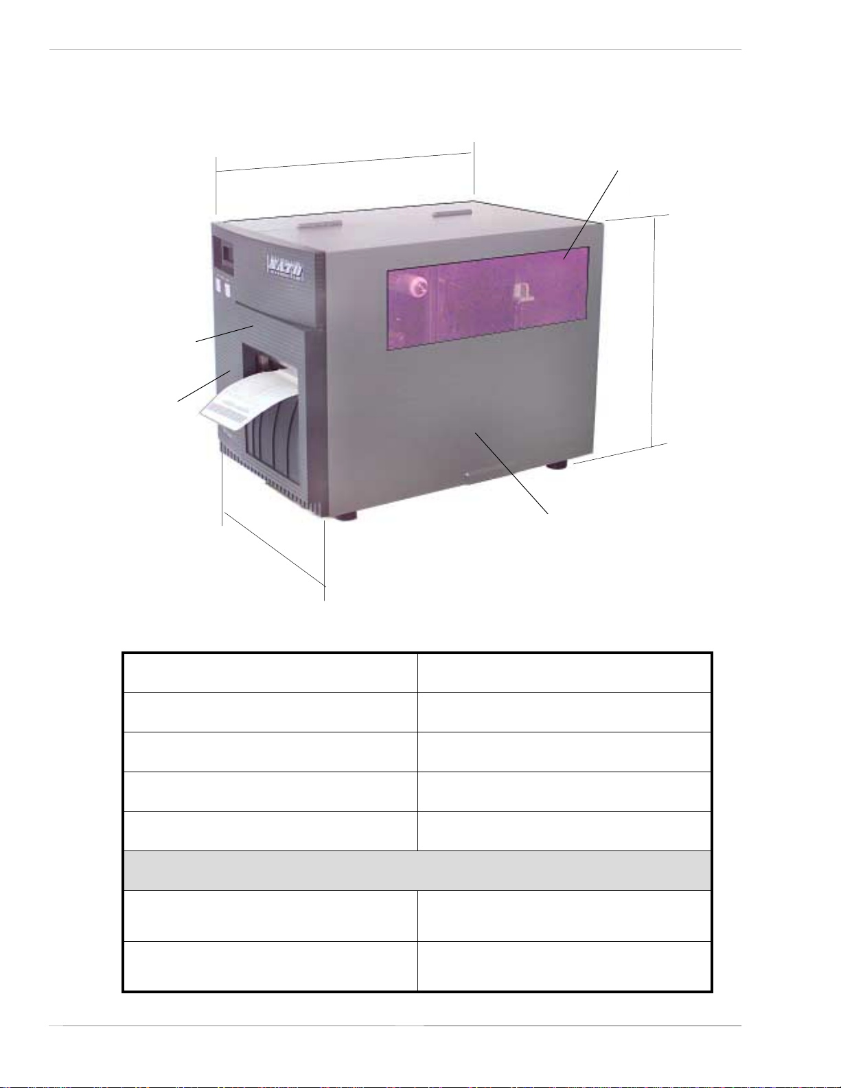
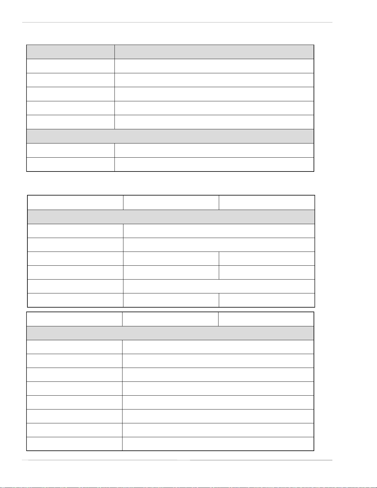
1.2 Physical Characteristics
FRONT ACCESS
DOOR
LABEL OUT
SLOT
Width
Depth
PAPER CHECK
WINDOW
Height
TOP ACCESS
DOOR
Page 1-2
snoisnemiDe214LCe804LC
ediW)mm172(.ni7.01
peeD)mm034(.ni9.61
hgiH)mm123(.ni6.21
thgieW)gk31(.sbl7.82
stnemeriuqeRrewoP
egatloV
noitpmusnoCrewoP
SA TO CL408e/CL412e Service Manual
)%01-/+(V022-511
)%1-/+(zH06/05
eldiW05
gnitarepOW031
PN 9001078
Rev. B
Page 9
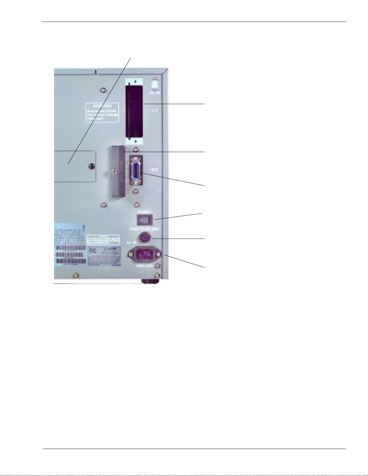
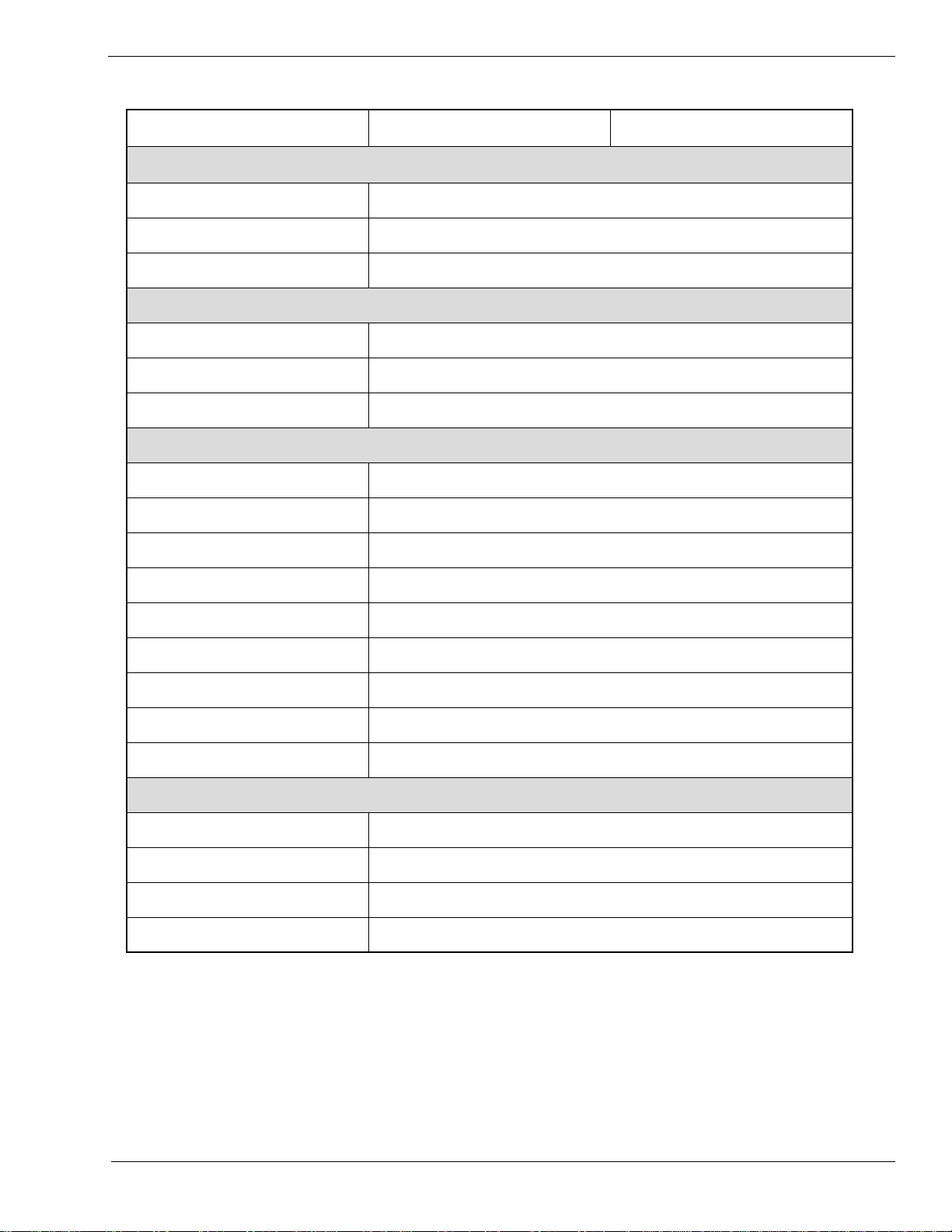
1.3 Printer Features
Section 1. Overview and Specifications
COVER PLATE-REMOVE FOR ACCESS
TO DISPENSER AND FAN-FOLD SLOTS
INTERFACE SLOT
PCMCIA MEMORY
EXPANSION SLOT
EXT CONNECTOR
POWER SWITCH
AC FUSE
AC POWER INPUT
CONNECTOR
Rear Panel
INTERFACE SLOT Slot to plug in an interface adapter. An adapter must be
connected before the printer is operational. The adapter types
available are:
RS232C Serial I/F Module, DB-25.
IEEE1284 Parallel I/F Module, AMP 57-40360
Universal Serial Bus I/F Module
Ethernet 10/100 BaseT I/F Module
RS-422/485 I/F Module, DB-9
MEMORY CARD SLOT One slot for optional PCMCIA Memory Cards.
PN 9001078
Rev. B
EXT CONNECTOR External signal connector for Accessories, AMP 57-60140
POWER SWITCH Turns power On/Off
AC FUSE Input power protection. Type 3A/250V.
AC POWER INPUT Input 115V 50/60 Hz connector. Use the cable provided.
SA TO CL408e/CL412e Service Manual
Page 1-3
Page 10
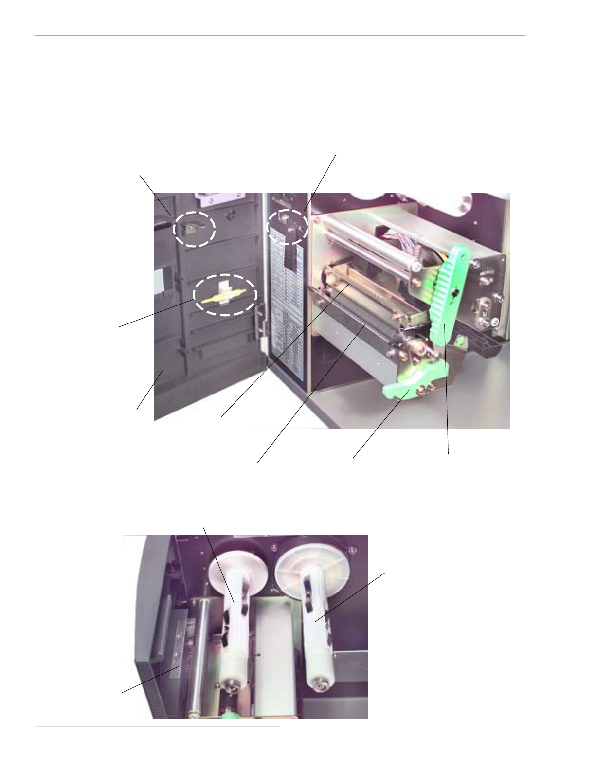
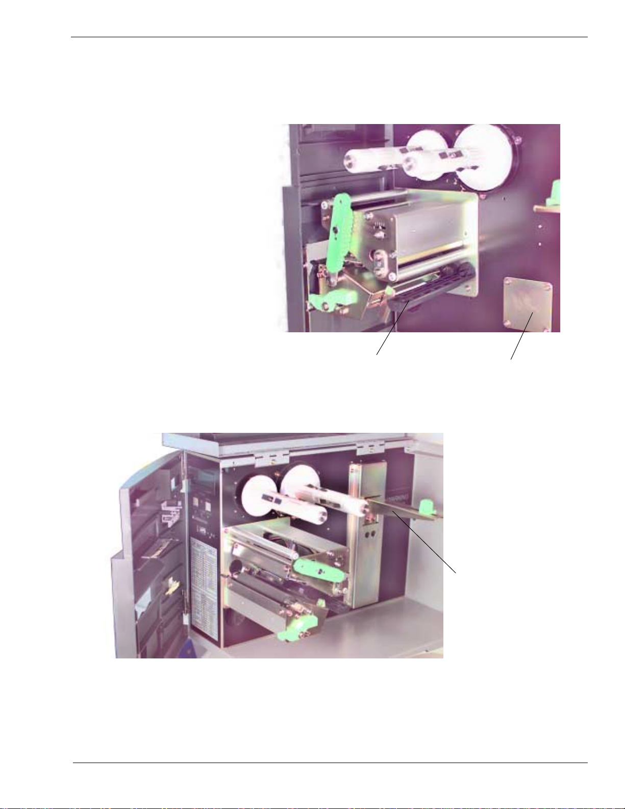
Section 1. Overview and Specifications
Printer Features
FRONT ACCESS DOOR
INTERLOCK :
This switch prevents printer
operation when the Front Access
Door is open. The Top Access
Door must be open before the
Front Access Door can be opened
or closed.
COVER OPEN SENSOR:
When this sensor is activated, the
printer will not operate and
Cover Open message will be
displayed on the display panel.
TOOL FOR
DARKNESS
ADJUSTMENT
FRONT ACCESS
DOOR OPENED
PRINT HEAD
ASSEMBLY UNIT
TEAR OFF
PLATE
RIBBON REWIND
SPINDLE
FRONT ACCESS
DOOR OPEN
LEVER
HEAD OPEN LEVER:
When the print head is
opened, this switch is
activated and the printer
will stop printing.
RIBBON SUPPLY
SPINDLE
BRUSH
(A TTACHED TO
DOOR)
Page 1-4
SA TO CL408e/CL412e Service Manual
PN 9001078
Rev. B
Page 11
Printer Features
Section 1. Overview and Specifications
LABEL GUIDE
ACCESS PLATE
FOR OPTIONAL
LABEL
DISPENSER
MEDIA HOLDER
PN 9001078
Rev. B
SA TO CL408e/CL412e Service Manual
Page 1-5
Page 12
Section 1. Overview and Specifications
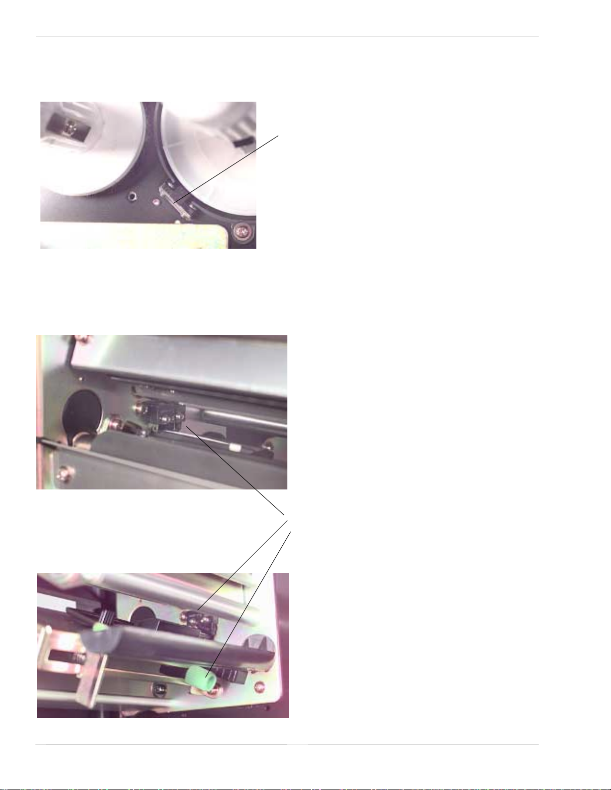
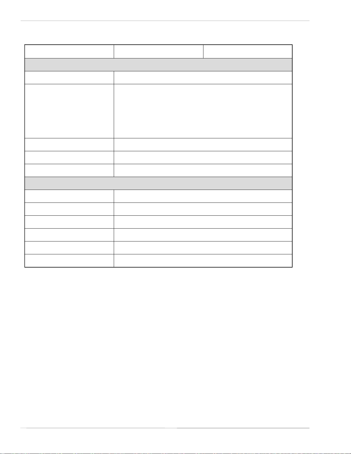
1.4 Sensors
RIBBON MOTION SENSOR:
This sensor is a motion detector that
signals the printer when the ribbon
supply is turning. This sensor is used
for both the ribbon end and ribbon
near end sensing.
LABEL SENSOR:
Both the "Eye-Mark" (reflective) and Gap
(transmissive) sensors can be adjusted over
a limited range. They are both located in
the label sensor unit. The assembly can be
adjusted by loosening the green sensor
knob located underneath the label transport
assembly and sliding the label sensor unit
to the desired position. The gap sensor can
be adjusted from a minimum of 0.67 in.
(17mm) to a maximum of 2.5 in. (64mm)
and the "Eye-Mark" from a minimum of
0.25 in. (6mm) to a maximum of 2.1 in.
(53mm) from the fixed position, "inside
label guide".
Page 1-6
SA TO CL408e/CL412e Service Manual
PN 9001078
Rev. B
Page 13
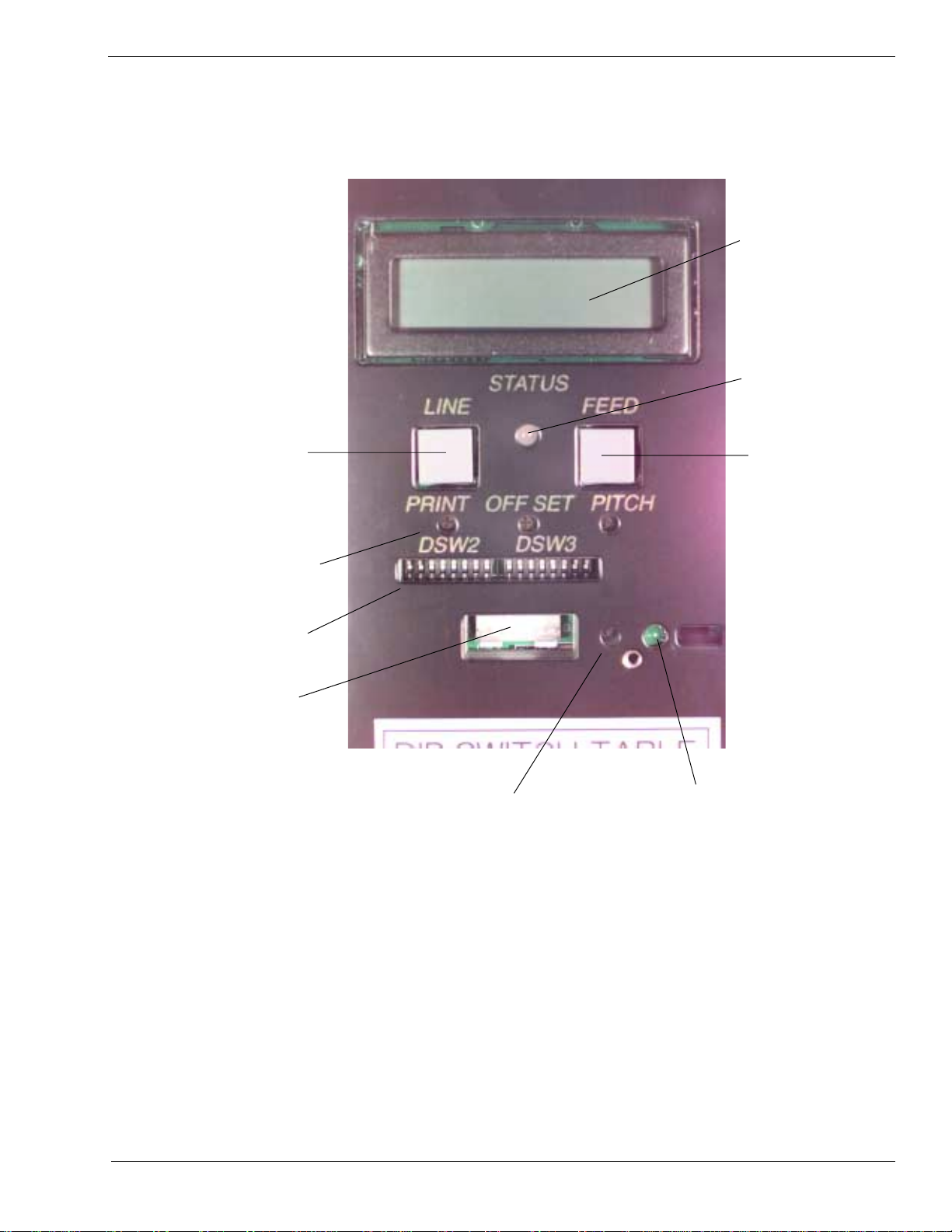
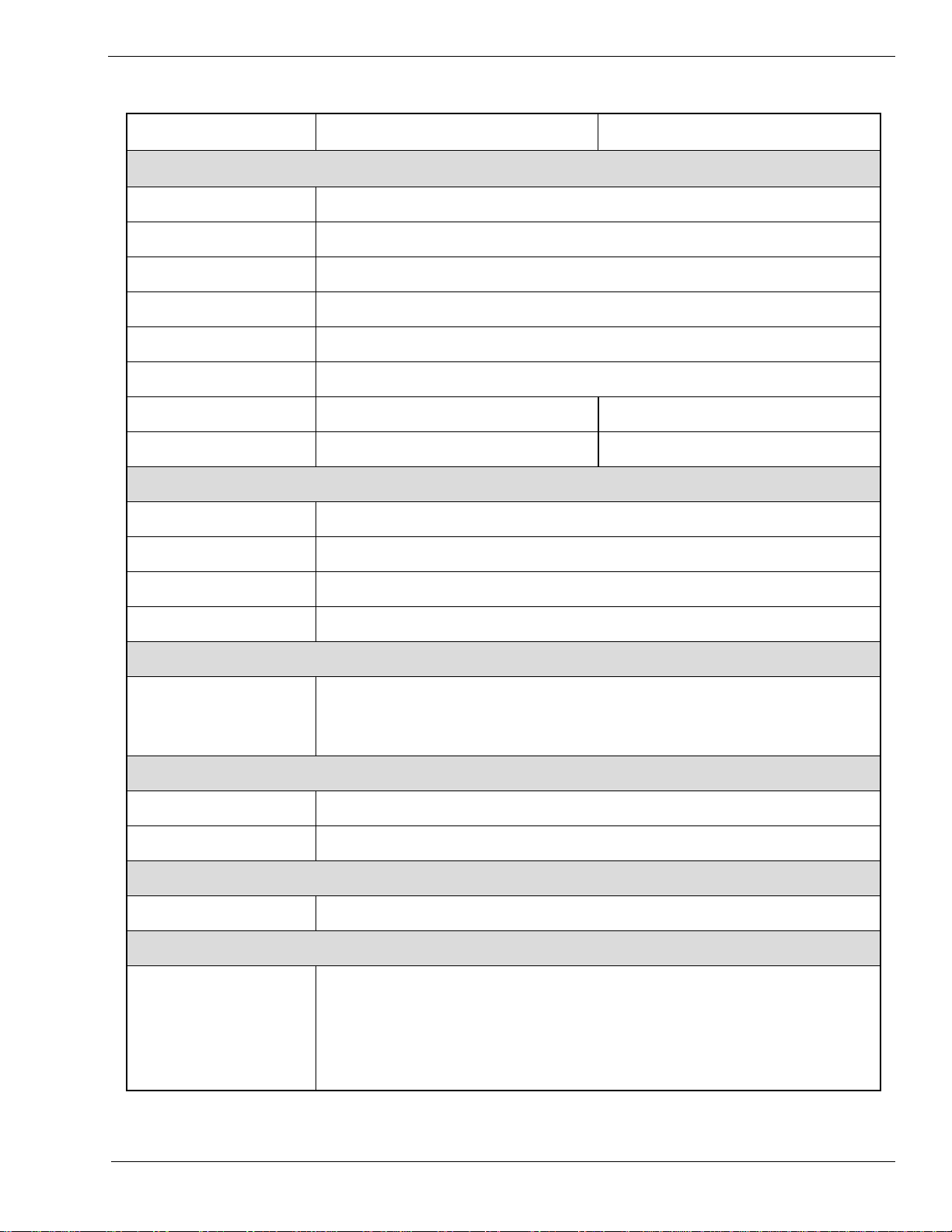
1.5 Operation Panel
Section 1. Overview and Specifications
LCD DISPLAY
PANEL
TWO-COLOR
STATUS LED
LINE KEY
PRINT/OFFSET/PITCH
POTENTIOMETERS
*DSW2 & 3
OPTION
CONNECTIOR
FEED KEY
LABEL TAKEN LED
LABEL T AKEN THRESHOLD
POTENTIOMETER
PN 9001078
Rev. B
*NOTE: Optional RS232 Communication Card contains DSW1 switches which are
configured when supplied with the printer.
The CL408e/CL412e Operator Panel consists of one two-color (red and green) LED
indicator, two momentary contact switches, two DIP switches (a third is located on the
RS232 interface card), four adjustment potentiometers and one LCD display. All of
these are accessible from the front of the printer, however some are not accessible
unless the front cover is open. They are used to set the printer operating parameters
and to indicate the status of the printer to the operator.
SA TO CL408e/CL412e Service Manual
Page 1-7
Page 14

Section 1. Overview and Specifications
Operation Panel
LCD DISPLAY PANEL 2 Line x 16 Character LCD display. Used for setting operational
parameters of the printer.
STATUS LED Two-color (Red, Green) LED that indicates the following status
conditions.
Green-Illuminated when printer is ready to receive data.
It is turned on and off by toggling the LINE key.
Red-Illuminated when there is a system fault such as an
open print head.
LINE KEY Momentary switch. Pressing this key toggles the printer between
the on-line and off-line mode. When the printer is on-line, it is
ready to receive data from the host. This key acts as a pause
during a print job by taking the printer off-line. It can also be
used as a PAUSE function key to stop label during the printing
process.
FEED KEY Momentary switch. Pressing this key feeds one blank label
through the printer when it is off-line. When the printer is online, there is a user selectable option in the Service Mode (see
page 2-28) to either print a copy of the previously printed label
or feed a blank label. The default is to feed a blank label.
POTENTIOMETERS
PRINT Located behind the Front Access Door. Potentiometer is used to
adjust print darkness (fine tuning).
OFFSET Located behind the Front Access Door. Potentiometer is used to
adjust amount of back/forward feed for dispenser/cutter/tear-off
bar position (+/- 3.75mm).
PITCH Located behind the Front Access Door. Potentiometer is used to
adjust home position of the label (+/- 3.75mm). Affects stop
position of label feed, print position and dispense position.
LABEL T AKEN Located behind the Front Access Door. Potentiometer is used to
THRESHOLD
adjust the sensing level of the Label Taken Sensor. Active only
when the Label Dispense option is installed.
DSW2 & DSW3 Located behind the Front Access Door. DIP switch array to set
operational parameters of the printer. DSW1 is used to set the
RS232 parameters and is located on the RS232 interface board if
installed in your printer.
OPTIONAL Located behind the Front Access Door. This connector is used for
CONNECTOR
the cutter and dispenser optional accessories.
LABEL TAKEN LED Located behind the Front Access Door. This LED is illiminated
when a label is not present in the Label Taken Sensor. If it is not
illuminated, a label has been detected in the sensor and printing
will be inhibited until it is removed. This LED is active only
when the Label Dispense option is installed.
Page 1-8
SA TO CL408e/CL412e Service Manual
PN 9001078
Rev. B
Page 15
Section 1. Overview and Specifications
1.6 Installation Considerations
Printer operation can be affected by the printer environment. The location of the
printer should be free from dust, humidity and sudden vibrations. To obtain optimum
results from the printer, avoid locations influenced by:
Direct or bright sunlight, since bright light will make the label sensor less responsive
and may cause the label to be sensed incorrectly.
Warm temperatures which can cause electrical problems within the printer. (See
Section 1-8 Environment.
1.7 Optional Accessories
YROSSECCA214LC/804LC
noisnapxEyromeM
.stnofepyTeurTdedaolnwod
*
4rohsalFBM61otpu(sdraCyromeMAICMCProftolsenO
rofdesuebnaC.MORhsalFlanretniBM4ro/dna)MARSBM
dnaegarotstamrof,noisnapxereffubtnirp,egarotselifcihparg
radnelaC
rettuClebaL
redniweRlebaL
ecafretnIlellaraPeludoMecafretnIlellaraP4821EEEI
ecafretnIlaireSeludoMecafretnI232SRlaireSdeepShgiH
resnepsiDlebaL
F/IlaireSlasrevinUeludoMecafretnIBSU
ecafretnItenrehtEeludoMecafretnITesaB001/01
ecafretnIxaniwT/xaoC
otdesuebnactahtpihcemiT/etaDdetnuomyllanretninA
.gnitnirpfoemitehttaslebalpmatsemit/etad
*
tatucebotslebalgniwollatnemhcattadetnuomyllanretninA
.gnimmargorphguorhtdellortnoC.slanretnideificeps
*
rofgnikcabmorfdeleepotslebalgniwollatnemhcattalanretnI
.pu-ekatgnikcablanretnI.noitacilppa)dnamedno(etaidemmi
erayehtretfalloraotnoslebalsdniwertahtnoitpolanretxE
.detnirp
2-7823MBInasetalumeF/IxaoC.eludoMecafretnIxairT/xaoC
F/IxaniwT.rotcennocCNBAepyTdradnatsahtiwretnirp
-otuahtiwsretnirp4124ro6225,5225,4225MBIsetalume
seitilibapacurht-elbac/etanimret
PN 9001078
Rev. B
Check with your software vendor to make sure these functions are supported.
*
SA TO CL408e/CL412e Service Manual
Page 1-9
Page 16
Section 1. Overview and Specifications
1.8 Environment & Approvals
latnemnorivnE e214LC/e804LC
erutarepmeTgnitarepO14
erutarepmeTegarotS0-
ytidimuHgnitarepOgnisnednoc-non,HR%58-51
ytidimuHegarotSgnisnednoc-non,HR%09xaM
egrahcsiDcitatsortcelEVK8
slavorppAyrotalugeR
ytefaSASC,LU
IME/IFRAssalCCCF
1.9 General Printer Specifications
noitacificepSe804LCe214LC
tnirP
dohteMrefsnarTlamrehTrotceriD
0
0
0
401ot
0
401ot
0
5(F
0
02-(F
0
04ot
)C
0
04ot
)C
)elbatceleSresU(deepSs/mm051ot05-spi6ot2
)eziStoD(eludoMtnirPmm521.-.ni9400.mm380.-.ni3300.
noituloseRmmpd8-ipd302mmpd21-ipd503
htdiWtnirPmumixaMmm401-.ni1.4
htgneLtnirPmumixaMmm9421-.ni2.94mm338-.ni8.23
noitacificepSe804LCe214LC
aideM
htdiWmuminiM)mm22(.ni78.
htgneLmuminiM)mm6(.ni42.
htdiWmumixaM)mm131(.ni1.5
epyT suounitnoCrokcotSgaT,dloF-naF,slebaLtuCeiD
repilaC)mm52.(.ni010.
)xam(DOlloRdniWni-ecaF,)mm812(.ni6.8
Page 1-10
)nim(DIeroC)mm83(.ni5.1
)dednemmoceR(DIeroC)mm67(.ni3
SA TO CL408e/CL412e Service Manual
PN 9001078
Rev. B
Page 17
General Printer Specifications
noitacificepSe804LCe214LC
gnisneS
urht-eeSevissimsnarTelbavoM
kraM-eyEevitcelfeRelbavoM
mroFsuounitnoCdesutonrosneS
nobbiR
htdiWmumixaM)mm111(.ni4.4
htgneL)m054(.tf5741
ssenkcihTdniWniecaF,norcim5.4
slangiSdnaslortnoC
Section 1. Overview and Specifications
DELeniL-nOneerG=sutatS
DELrewoPenoN
DELtuOaideMdeR=sutatS
DELtuOnobbiRdeR=sutatS
DELrorrEdeR=sutatS
lenaPDCLretcarahC61xeniL2
hctiwSeniL-ffO/nOlenaPtnorF
hctiwSdeeFlebaLlenaPtnorF
hctiwSffO/nOrewoPlenaPraeR
stnemtsujdAretemoitnetoP
ssenkraDtnirPlenaPtnorF
hctiPlenaPtnorF
tesffOlenaPtnorF
)1(
)1(
)1(
)1(
PN 9001078
Rev. B
yalpsiDenoN
(1) Single two color (Red, Green) LED
SA TO CL408e/CL412e Service Manual
Page 1-11
Page 18
Section 1. Overview and Specifications
General Printer Specifications
noitacificepSe804LCe214LC
seludoMecafretnI
lellaraPlellaraP4821EEEI
laireS
locotorPlaireS
suBlaireSlasrevinU1.1noisreVBSU
tenrehtETesaB001/01
noissimsnarTataDtamroFIICSA
gnissecorP
)spb006,75ot0069(C232SR
)spb006,75ot0069(584/224SR
)ysuB/ydaeR(lortnoCwolFerawdraH
)ffO-X/nO-X(lortnoCwolFerawtfoS
4ro3,2sutatSlanoitcerid-iB
UPCCSIRtiB23
MORhsalFBM2
MARDSBM61
reffuBevieceRBM59.2
MORhsalFlanoitpOBM4
yromeMAICMCPlanoitpOMARSBM4rohsalFBM61otpU
Page 1-12
SA TO CL408e/CL412e Service Manual
PN 9001078
Rev. B
Page 19
1.10 Character Fonts
noitacificepSe804LCe214LC
stnoFxirtaM
tnoFU)Hstod9xWstod5(
tnoFS)Hstod51xWstod8(
tnoFM)Hstod02XWstod31(
tnoFUXacitevleH)Hstod9xWstod5(
tnoFSX dloBdesnednoCsrevinU)Hstod71xWstod71(
tnoFMX dloBdesnednoCsrevinU)Hstod42xWstod42(
tnoFAOA-RCO)Hstod22xWstod51(A-RCO)Hstod33xWstod22(
tnoFBOB-RCO)Hstod42xWstod02(B-RCO)Hstod63xWstod03(
stnoFgnihtoomSotuA
Section 1. Overview and Specifications
BW)Hstod03xWstod81(tnoFBW
LW)Hstod25xWstod82(tnoFLW
BX dloBdesnednoCsrevinU)Hstod84xWstod84(tnoFBX
LX fireSsnaS)Hstod84xWstod84(tnoFLX
tnoFrotceV
®
stnoFretsaRAFGA
tnoFAtp27ot8,semiTGC
tnoFBtp27ot8,etarivmuirTGC
stnoFelbadaolnwoD
lortnoCretcarahC
gnicapSdexiFrolanoitroporP
stod999x999otstod05x05eziStnoF
snoitairaVtnoF01,acitevleH
margorPytilitUhtiwstnoFepyTeurTdeppaMtiB
PN 9001078
Rev. B
0
0
SA TO CL408e/CL412e Service Manual
0
09,
0
081,
setanidroocYroXehtrehtieniX21otpunoisnapxE
lortnochctiPretcarahC
lortnocecapSeniL
ytilicaftnirPlanruoJ
0
072dna
noitatoR
Page 1-13
Page 20
Section 1. Overview and Specifications
1.1 1 Bar Codes
noitacificepSe804LCe214LC
seigolobmyS
)latnemelppuSNAE/CPU(dnalkooB
31-NAE,8-NAE
RABADOC
93edoC
39edoC
821edoC
5fo2devaelretnI
5fo2lairtsudnI
5fo2xirtaM
ISM
TENTSOP
821-NAE/CCU
E-CPUdnaA-CPU
soitaR shtdiwrabelbanifedresU5:2,3:1,2:1
thgieHraBelbammargorpresU,stod006ot4
0
0
noitatoR0
09,
0
081,
0
072dna
serutaeFrehtO
gnirebmuNlaitneuqeS sedocrabdnasciremunhtobfognirebmunlaitneuqeS
sretcarahCmotsuCsretcarahclaicepsrofegarotsMAR
scihparG
stamrof
XCP.roPMB.,yraniB/xeHOTAS,scihpargelbasserddatodlluF
yalrrevOmroF stamrofxelpmocfognitidedeeps-hgihrofyalrevomroF
Page 1-14
SA TO CL408e/CL412e Service Manual
PN 9001078
Rev. B
Page 21
Section
Configuration
2
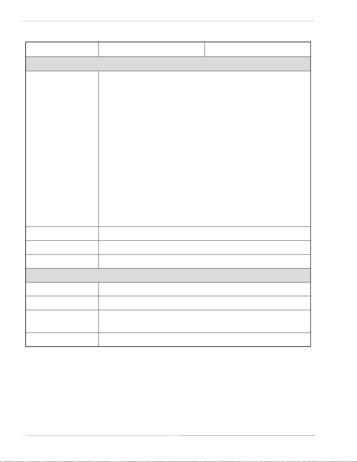
2.1 Dip Switch Settings
Two DIP switches (DSW2 & DSW3) are located inside the Front Access Door.
These switches can be used to set:
• Thermal transfer or direct thermal mode
• Head Check Mode
• Hex Dump Mode
• Label sensor enable/disable
• Single Job or Multi-Job Receive Buffer
• Operation Mode
DIP SWITCHES
In addition, a third DIP switch (DSW1) is located on the optional RS232 Serial
Adapter card and is used to set the RS232C transmit/receive parameters.
DSW1
Each switch is an eight section toggle switch. The On position is always to the
top. To set the switches, first power the unit Off, then position the DIP switches.
Finally after placing the switches in the desired positions, power the printer back
on. The switch settings are read by the printer electronics during the power-up
sequence. They will not become effect until the power is cycled.
PN 9001078
Rev. B
SA TO CL408e/CL412e Service Manual
Page 2-1
Page 22
Section 2. Configuration
Dip Switch Settings
RS232 Transmit/Receive Setting (located on RS232 I/F Module)
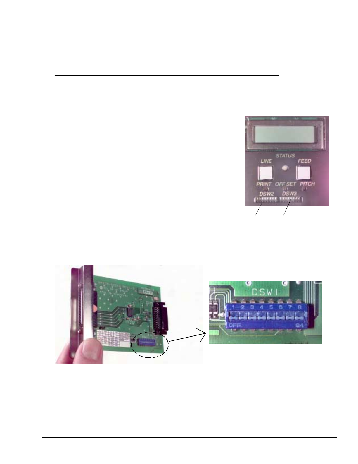
Data Bit Selection (DSW1-1): This switch sets the printer to receive either 7 or 8
data bits for each byte transmitted.
DSW1-1 SETTING
ON
DSW1
Off 8 data bits
OFF
On 7 data bits
1 2 3 4
5 6 7 8
Parity Selection (DSW1-2, DSW1-3): These switches select the type of parity used
for error detection.
DSW1-2 DSW1-3 SETTING
DSW1
Off Off None
ON
Off On Even
On Off Odd
OFF
On On Not Used
1 2 3 4
5 6 7 8
Stop Bit Selection (DSW1-4): Selects the number of stop bits to end each byte
transmission.
DSW1
DSW1-4 SETTING
Off 1 Stop Bit
ON
OFF
On 2 Stop Bits
1 2 3 4
5 6 7 8
Baud Rate Selection (DSW1-5, DSW1-6): Selects the data rate (bps) for the RS232
port.
DSW1
DSW1-5 DSW1-6 SETTING
ON
Off Off 9600
Off On 19200
On Off 38400
On On 57600
OFF
1 2 3 4
5 6 7 8
Protocol Selection (DSW1-7, DSW1-8): Selects the flow control and status
reporting protocols.
(* Will select protocol Bi-Com 2 for M-8400 if DSW2-8 is ON)
DSW1-7 DSW1-8 SETTING
Off Off Rdy/Bsy
Off On Xon/Xoff
ON
OFF
DSW1
On Off Bi-Com 3
On On Bi-Com 4*
1 2 3 4
5 6 7 8
Page 2-2
SA T O CL408e/CL412e Service Manual
PN 9001078
Rev. B
Page 23
Section 2. Configuration
Dip Switch Settings
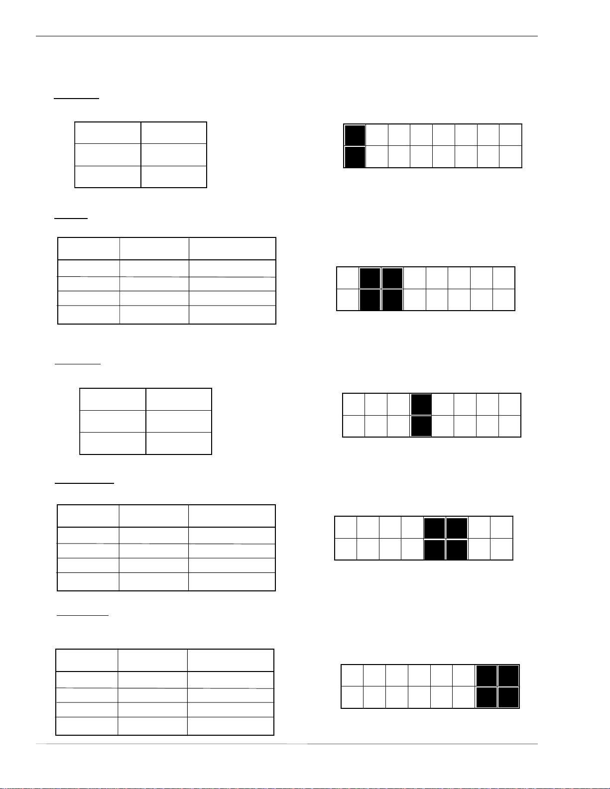
Printer Set up
Print Mode Selection (DSW2-1): Selects between direct thermal printing on
thermally sensitive paper and thermal transfer printing using a ribbon
DSW2
DSW2-1 SETTING
Off Transfer
On Direct Therm
ON
OFF
1 2 3 4
5 6 7 8
Sensor Type Selection (DSW2-2): Selects between the use of a label gap or a
reflective Eye-Mark.
DSW2
DSW2-2 SETTING
Off Gap
ON
OFF
On Eye-Mark
1 2 3 4
5 6 7 8
Head Check Selection (DSW2-3): When selected, the printer will check for head
elements that are electrically malfunctioning.
DSW2
DSW2-3 SETTING
Off Disable
ON
OFF
On Enable
1 2 3 4
5 6 7 8
Hex Dump Selection (DSW2-4):Selects Hex Dump mode.
DSW2
DSW2-4 SETTING
Off Disable
ON
OFF
On Enable
1 2 3 4
5 6 7 8
Receive Buffer Selection (DSW2-5): Selects the operating mode of the receive
buffer. See Section 3: Interface Specifications for more information.
DSW2
DSW2-5 SETTING
Off 1 Item
ON
OFF
On Multi-Job
1 2 3 4
5 6 7 8
For more information about the cause of troubleshooting printer errors, see
Section 8, Troubleshooting.
PN 9001078
Rev. B
SA T O CL408e/CL412e Service Manual
Page 2-3
Page 24
Section 2. Configuration
Dip Switch Settings
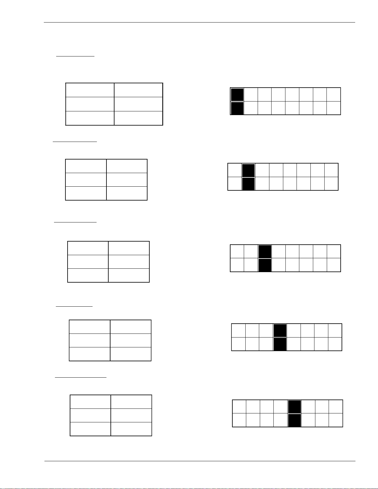
Firmware Download (DSW2-6): Places the printer in the Firmware Download mode
for downloading new firmware into flash ROM.
DSW2
DSW2-6 SETTING
Off Disabled
On Enabled
ON
OFF
1 2 3 4
5 6 7 8
Protocol Code Selection (DSW2-7): Selects the command code set used.
DSW2
DSW2-7 SETTING
Off Standard
ON
OFF
On Non-Std.
1 2 3 4
5 6 7 8
M8400 Emulation Mode (DSW2-8): For emulating earlier series software
commands. Should be used only if problems are encountered when using existing
software. This switch will also affect the setttings selected by DSW1-7 and DSW1-8.
DSW2
DSW2-8 SETTING
ON
Off Disabled
On Enabled
OFF
1 2 3 4
5 6 7 8
Mode Selection (DSW3-1 and DSW3-2): Selects the operating mode of the printer.
Batch/Continuous disables the label taken (dispense option) sensor.
DSW3
DSW3-1 DSW3-2 SETTING
ON
Off Off Batch/Continuous
OFF
Off On Tear Off
1 2 3 4
5 6 7 8
On Off Cutter
On On Dispenser
Page 2-4
SA T O CL408e/CL412e Service Manual
PN 9001078
Rev. B
Page 25
Section 2. Configuration
Dip Switch Settings
Label Sensor Selection (DSW3-3): Enables or disables the Label Pitch sensor. If the
sensor is enabled, it will detect the edge of the label and position it automatically. If
it is disabled, the positioning must be under software control using Line Feed
commands.
DSW3
DSW3-3 SETTING
Off Sensor Used
On Sensor Not
Used
ON
OFF
1 2 3 4
5 6 7 8
Back-Feed Selection (DSW3-4): When Back-Feed is enabled, the printer will
position the label for dispensing/cutting and retract it before printing the next label.
The amount of backfeed is adjustable.
DSW3
DSW3-4 SETTING
Off Enabled
ON
OFF
On Disabled
1 2 3 4
5 6 7 8
External Signal Interface
The EXT connector on the printer rear panel is intended for use with the external
printer accessories such as label rewinders or applicators. The 14-pin Centronics
type connector provides a choice of four different output signals along with various
error conditions.
PN 9001078
Rev. B
EXT Print Start Signal Selection (DSW3-5): Allows an external device to initiate
a label print for synchronization with the applicator. See Section 3: Interface
Specifications for a description of the signal level and requirements. When DSW35 is On, the unit is in the Continuous print mode, Backfeed is disabled an External
Signals are ignored.
DSW3
DSW3-5 SETTING
Off Disabled
ON
OFF
On Enabled
1 2 3 4
SA T O CL408e/CL412e Service Manual
5 6 7 8
Page 2-5
Page 26
Section 2. Configuration
Dip Switch Settings
External Signal Type Selection (DSW3-6, DSW3-7): Both the polarity and signal
type (level or pulse) of the external print synchronizing signal can be selected. See
Section 3 for a definition of signal types.
DSW3-6 DSW3-7 SETTING
DSW3
ON
Off Off Type 4
OFF
Off On Type 3
On O ff Type 2
1 2 3 4
5 6 7 8
On On Type 1
Repeat Print via External Signal (DSW3-8): Allows an applicator or other device
to reprint the last label of the print job. See Section 3: Interface Specifications for a
description of the signal requirements.
DSW3
DSW3-8 SETTING
Off Disabled
ON
OFF
On Enabled
1 2 3 4
5 6 7 8
Page 2-6
SA T O CL408e/CL412e Service Manual
PN 9001078
Rev. B
Page 27
Section 2. Configuration
2.2 Default Settings
Dip Switch Selections
All switches are placed in the Off position (default) except Receive Buffer for shipping.
This will result in the following operating configuration:
Communications:
Protocol:
Sensor: Gap Sensor
Receive Buffer: Multi-Job
Mode: Batch Continuous
Label Sensor: Sensor Used
Backfeed: Enabled
External Signals: Disabled
(1) Applicable only if an RS232 Interface Card is installed in the printer.
Software Default Settings - The printer stores any software settings upon receipt from
the host and uses them until they are again changed by receipt of a command
containing a new setting. These settings are stored in non-volatile memory and are
not affected by powering the printer off. The printer may be reset to use the default
software settings by depressing the LINE and FEED keys simultaneously while
powering the printer on. You will be asked to confirm that you want the printer
default settings by selecting either YES or NO by using the LINE key to step the
underline cursor to the desired setting. If you select YES and press the FEED key, the
following default configuration will be stored:
(1)
(1)
8 data bits, no parity, 1 Stop bit, 9600 Baud
Ready/Busy
(1)
e214LC/e804LC
ssenkraDtnirP3
deepStnirP.cesrep.ni4
ecnerefeRtnirP0000=latnoziroH,0000=lacitreV
oreZhsalS
eniL-nOotuAdelbanE
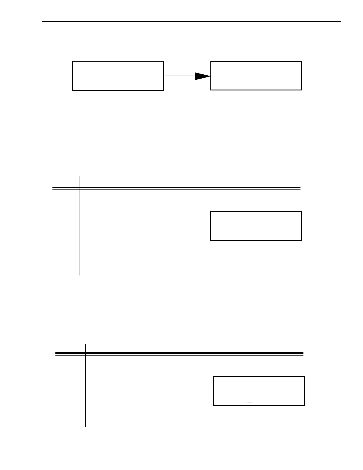
Once the default operation is completed, a DEFAULT SETTING COMPLETED
message will be displayed on the LCD panel and a single "beep" will be heard. The
printer should be powered off while this message is being displayed. This saves the
default settings in the EEPROM where they will be automatically loaded the next time
the printer is powered on.
DEFAULT SETTING
COMPLETED
PN 9001078
Rev. B
SA T O CL408e/CL412e Service Manual
Page 2-7
Page 28
Section 2. Configuration
2.3 LCD Panel Configuration
The LCD Panel on the CL408e/CL412e is used in conjunction with the LINE and FEED
switches by the operator to manually enter printer configuration settings. Many of the
settings can also be controlled via software commands and in the case of conflict between
software and control panel settings, the printer will always use the last valid setting. If you
load a label job that includes software settings and then enter a new setting via the LCD
Panel, the manually set values will be used by the printer. If you set the values manually
and then download a job with software settings, the software settings will be used.
There are 7 configuration and operation modes you can access from the LCD panel. To
enter the desired mode, the KEY SEQUENCE combination listed in the table below must be
performed. The initial LCD display message is shown for each mode.
EDOMECNEUQESYEKYALPSIDLAITINIEGAP
edoMlamroNrewoP
ENILNO
000000:YTQ
edoMdecnavdAREWOP+ENILEDOMDECNAVDA31-2
edoMtnirPtseTREWOP+DEEF
edoMgnitteStluafeD
)locotorPdtS(
edoMecnanetniaM
edoMpmuDxeHREWOP+NO4-2WSD
erawmriF
edoMdaolnwoD
REWOP+DEEF+ENIL
+ENIL+NO4-2WSD
REWOP+DEEF
ENILNO
REWOP+NO6-2WSD
YDAER
EDOMTNIRPTSET
NOITARUGIFNOC
GNITTESTLUAFED
ONSEY
FFO>-NO4-2WSPID
000000:YTQ
DAOLNWODHSALF
9-2
33-2
43-2
EDOMECNANETNIAM
53-2
83-2
93-2
Page 2-8
SA T O CL408e/CL412e Service Manual
PN 9001078
Rev. B
Page 29
Section 2. Configuration
LCD Panel — Normal Mode
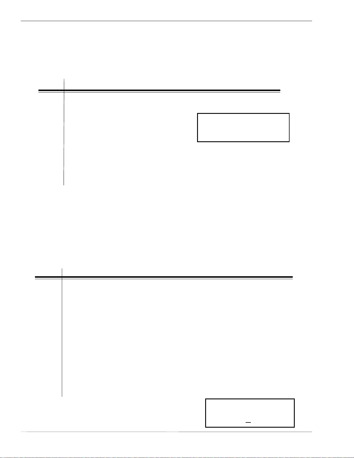
When the printer is first powered on it displays the current ROM version of the printer
then immediately displays the ONLINE mode.
initializing
rom v0.00.00.00
The LCD Panel will display the ONLINE status on the top line of the display. The bottom
line will contain the label quantity (QTY) status. The message will be changed to
OFFLINE whenever the printer is switched offline by depressing the LINE key. As soon as
a print job is received, the QTY message will indicate the number of labels to be printed.
As soon as the label job begins to print, the display will indicate the number of labels
remaining in the print job that remain to be printed. The user can access the User
Settings using the following procedures.
ONLINE
QTY: 000000
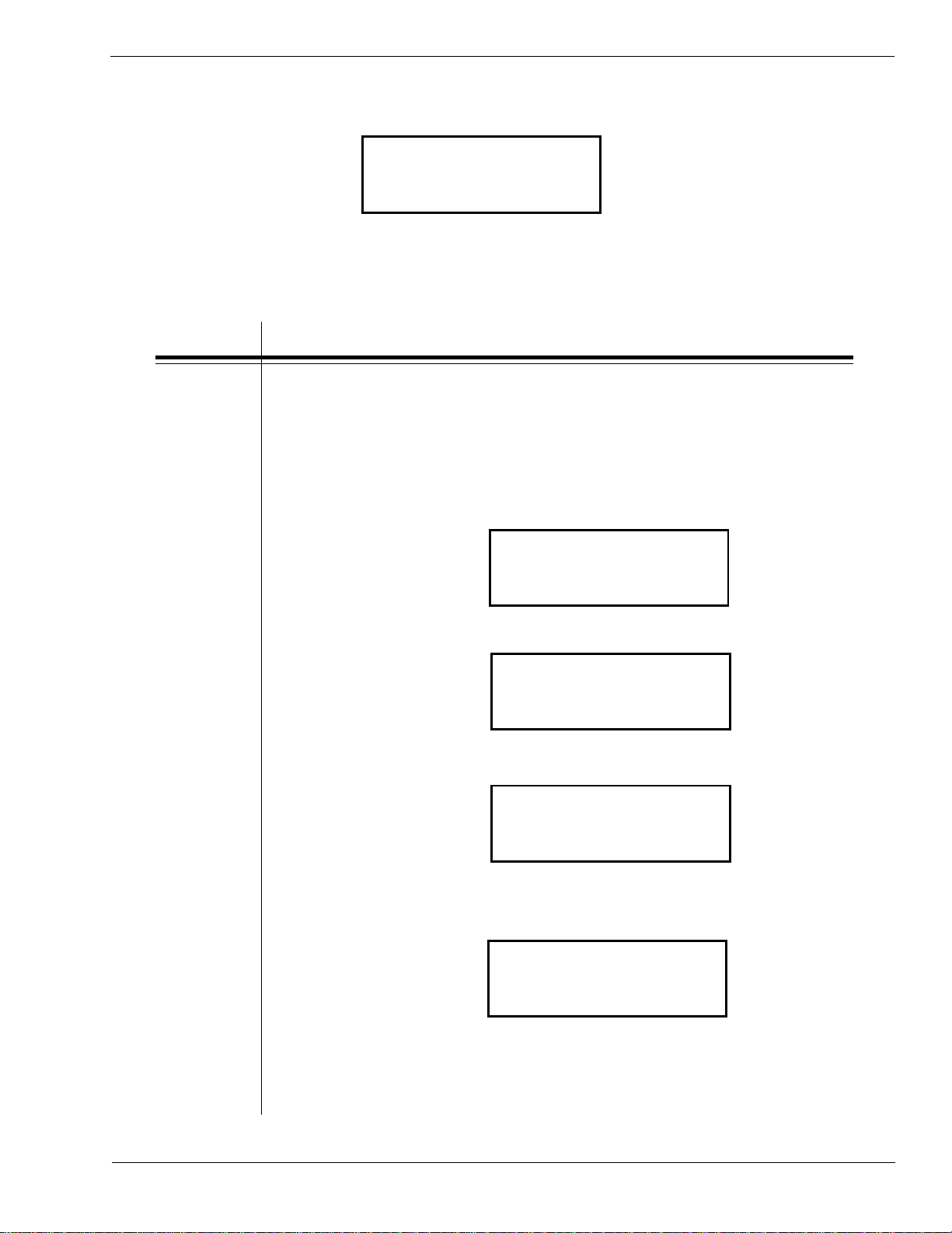
User Settings
STEP PROCEDURE
1. The printer is first taken offline by pressing the LINE key once.
The display will change to OFFLINE.
OFFLINE
000000
2. Press the LINEand FEED keys simultaneously for more than one
second. The printer now displays the first USER mode
adjustment (Print Darkness).
Print Darkness Setting
There are five Darkness (or heat range) settings on the printer. The higher
numbers represent darker settings. The current setting is indicated by a line under
one of the range settings.
To change the setting perform the following steps:
STEP PROCEDURE
1. Use the LINE key to step the underlined cursor to the desired
setting.
2. Once the correct setting is underlined, press the FEED key to
accept the setting and advance to the next adjustment.
1 = Light
2 = Slightly Light
3 = Medium
4 = Slightly Dark
5 = Dark
PRINT DARKNESS
12 345
PN 9001078
Rev. B
SA T O CL408e/CL412e Service Manual
Page 2-9
Page 30
Section 2. Configuration
LCD Panel — Normal Mode
Print Speed Adjustment
There are five Speed settings on the printer. The setting is listed on the bottom line
of the display. The current setting is indicated by an underline under one of the
speed settings. To change the setting:
STEP PROCEDURE
1. Use the LINE key to step the underlined cursor to the desired
speed setting.
2 = 2 in/s (50mm/s)
PRINT speed
3 = 3 in/s (75mm/s)
4 = 4 in/s (100mm/s)
5 = 5 in/s (125mm/s)
6 = 6 in/s (150mm/s)
2. Once the correct setting is underlined, press the FEED key to
accept the setting and advance to the next adjustment.
Pitch Offset Adjustment
The label pitch is the distance from the leading edge (the edge that comes out of the
printer first) of a label and the leading edge of the next label. The leading edge position of
the label can be adjusted relative to the print head +/- 49mm in increments of 1mm.
Once the position is set, it can be fine adjusted +/- 3.75mm using the PITCH
potentiometer on the adjustment panel.
STEP PROCEDURE
1. The underline cursor will initially be positioned underneath the Pitch
Direction setting. Use the LINE key to step the underline to either the
positive (+) or negative (-) selection. A position selection moves the
leading edge of the label forward (away from the print head) while a
negative selection moves the leading edge of the label back into the
mechansim.
2345 6
2. Once the correct setting is underlined, press the FEED key to
3. Use the LINE Key to step the first digit of the counter to the desired setting.
Page 2-10
accept the setting and advance to the Offset adjustment.
The display will increment one step each time the LINE key is pressed. The
reading will advance to a setting of 4 after which it will automatically wrap
and start at 0 again.
pitch offset
+00mm
SA T O CL408e/CL412e Service Manual
PN 9001078
Rev. B
Page 31

LCD Panel — Normal Mode
Pitch Offset Adjustment
STEP PROCEDURE
4. Press the FEED key to accept the setting and advance the cursor to the
second digit. Again use the LINE key to step to the desired setting.
Once it is correct, press the FEED key to advance to the next
adjustment.
Print a test label after completing the adjustments to ensure it is
correct.
Leading Edge of Label
A B C D E F G
Section 2. Configuration
Moved with negative (-)
offset to print on leading
edge of the label
Line Feed Direction
A B C D E F G
A B C D E F G
Original (0 offset) first
line position
Moved with positive (+)
offset to print on trailing
edge of the label
Sensor Position
PN 9001078
Rev. B
SA T O CL408e/CL412e Service Manual
Page 2-11
Page 32

Section 2. Configuration
LCD Panel— Normal Mode
Cancel Print Job
If the printer has a print job(s) loaded in memory, selecting YESwill cause the
job(s) to be cleared. The default selection is NO. Make sure that you want to
cancel the print job before selecting YES as the job cannot be recovered and will
have to be retransmitted to the printer.
To cancel the print, perform the following steps:
cancel print job
yes no
STEP PROCEDURE
1. Use the LINE key to step the underlined cursor to either
No or Yes.
2. Once the correct setting is underlined, press the FEED key to accept
the setting.
3. After the print job(s) have been cleared from memory, the printer will
display a COMPLETED message for 3 seconds and then return to the
initial ONLINE Normal Mode.
cancel print job
COMPLETED
If you wish to change any of the settings, you must enter the User
mode again by taking the printer OFFLINE and simultaneously
pressing FEED and LINEkeys.
Page 2-12
SATO CL408e/CL412e Service Manual
PN 9001078
Rev. B
Page 33

Section 2. Configuration
LCD Panel— Advanced Mode
Advanced mode is provided to make adjustments that require only occasional adjustments.
Since they affect the basic operation of the printer, the procedure for entering this mode is
designed to prevent someone from accidentally changing the settings.
To Enter Advanced Mode:
STEP PROCEDURE
1. Press the LINE key while simultaneously turning the power on.
When the printer emits one long beep, release the LINE key to
display the first screen.
initializing
advanced mode
rom v00.00.00.00
2. Press the FEED key to display the Zero Slash display.
Zero Slash
ZERO SLASH
YES NO
This setting determines if a zero is printed with a slash or without a slash. This setting can
also be controlled via software commands. When YES is selected, the printer internal fonts
will have a slash through the center of the zero character.
STEP PROCEDURE
1. Use the LINE key to step the underlined cursor to either Ye s or No.
2. Once the correct setting is underlined, press the FEED key to accept
the setting and advance to the Auto Online display.
PN 9001078
Rev. B
AutoOnline
auto online
YES NO
This setting determines the mode in which the printer powers up. If YES is selected the
printer powers up in the ONLINE mode and is ready to print. If NO is selected, the
printer powers up in the OFFLINE mode and must be manually placed in the ONLINE
mode by pressing the LINE key before it is ready to print.
STEP PROCEDURE
1. Use the LINE key to step the underline to either the YES or NO
selection.
2. Once the correct setting is underlined, press the FEED key to accept
the setting and advance the display to the Offset display.
SA T O CL408e/CL412e Service Manual
Page 2-13
Page 34

Section 2. Configuration
LCD Panel — Advanced Mode
Print Offset
Print offset
v:+0000 H:+000
Since the printer moves the label in discrete steps equal to the size of the print dot, the
units of measure for Vertical and Horizontal Offset distance is dots.
Vertical Offset is the distance down from the leading edge in dots (the edge of the
label that comes out of the printer first) to the first vertical print position. A positive
setting moves the first print position down the length of the label while making it
negative moves it up the length of the label. The maximum value that can be set is 823
dots.
Horizontal Offset is the distance that the label image is shifted either to the right or
left on the label. For a positive setting the image is shifted to the left (towards the inside
edge of the label). For a negative setting the image the image is shifted to the right
(towards the outside edge of the label). This setting changes the base reference point for
all subsequent label jobs. The effect is identical to the <ESC>A3 Base Reference point
command. The maximum value that can be set is 1424 dots.
STEP PROCEDURE
1. Use the LINE key to step the first digit of the counter to the desired setting.
The display will increment one step each time the LINE key is pressed.
2. Press the FEED key to accept the setting and advance the cursor to the
second digit. Again use the LINE key to step to the desired setting. Once it
is correct, press the FEED key to advance to the next adjustment.
3. Once the setting is correct, press the FEED key to accept the setting and
advance to the next display.
Print a test label after completing the adjustments to ensure it is correct.
Note: This setting can be overridden by the Base Reference Point Command in
your software.
Set Calendar
set calendar
YES NO
This message will only be displayed if the Calendar Option is installed in the printer.
The Calendar is an optional feature in CL408e/CL412e printers allowing the date and time
to be set manually using the LCD Display or via the <ESC>WT Calendar Set command.
The last setting, set either manually via software command, received by the printer will be
the value used. The format of the display is YY/MM/DD hh:mm (Year/Month/Day/
hours:minutes). The date format is fixed and cannot be changed.
To enable the Calendar feature (if installed), press the LINE key until the underline cursor
is beneath the YES. If the Calendar feature is to be disabled, press the LINE key until the
cursor is underneath the NO. When the desired setting is selected, Press the FEED key.
Page 2-14
SA T O CL408e/CL412e Service Manual
PN 9001078
Rev. B
Page 35

LCD Panel — Advanced Mode
Set Calendar
(Continued)
Section 2. Configuration
Calendar
calendar
00/00/00 00:00
00/00/00 00:00
STEP PROCEDURE
1. Year - The first display shown will have the two digit year selection
underlined. You can scroll through the dates by pressing the LINE
key. The year number will increase by one each time the LINE key is
pressed until it reaches its maximum leagal value (i.e., "99" for the
year digits) at which point it will wrap around to the "00" setting.
2. Month - After you have set the correct year, pressing the FEED key
will advance the underline cursor to the two digit Month position.
You can scroll through the numbers corresponding to the month by
pressing the LINE key. The month number will increase by one each
time the LINE key is pressed until it reaches a value of "12" at which
point it will wrap around to the "01" setting.
3. Day - After you have set the correct month, pressing the FEED key
will advance the underline cursor to the two digit Day position. You
can scroll through the numbers corresponding to the month date by
pressing the LINE key. The date number will increase by one each
time the LINE key is pressed until it reaches a value of "31" at which
point it will wrap around to the "01" setting.
4. Hour - After you have set the correct date, pressing the FEED key
will advance the underline cursor to the two digit Hour position. You
can scroll through the numbers corresponding to the hour (using a 24
hour clock) by pressing the LINE key. The hour number will increase
by one each time the LINE key is pressed until it reaches a value of
"24" at which point it will wrap around to the "01" setting.
5. Minute - After you have set the correct hour, pressing the FEED key
will advance the underline cursor to the two digit Minute position.
You can scroll through the numbers corresponding to the hour by
pressing the LINE key. The minute number will increase by one each
time the line key is pressed until it reaches a value of "60" at which
point it will wrap around to the "01" setting.
6. After you have set the minutes, pressing the FEED key will accept the
setting and advance to the Ignore CR/LF selection.
PN 9001078
Rev. B
SA T O CL408e/CL412e Service Manual
Page 2-15
Page 36

Section 2. Configuration
LCD Panel — Advanced Mode
Ignore CR/LF
ignore cr/lf
YES NO
This setting tells the printer to strip out all carriage return/line feed pairs (CRLF) from the
data stream, including graphics and 2D bar codes. It is used primarily to maintain
compatibility with earlier models of SATO printers.
STEP PROCEDURE
1. Use the LINE key to step the underlined cursor to either YES or NO.
2. Once the desired setting is underlined, press the FEED key to accept
the setting and advance to the Character Pitch display.
Character Pitch
character pitch
prop fixed
This setting allows you to set the default character pitch to either fixed character spacing
or proportional character spacing.
STEP PROCEDURE
1. Use the LINE key to step the underlined cursor to the desired setting.
2. Once the desired setting is underlined, press the FEED key to accept
the setting and advance to Cover Open Sensor display.
Note: This command can be overriden by the <ESC>PR or <ESC>PS
Character Pitch Commands.
Cover Open Sensor
cover open sensor
Yes No
This setting allows the user to enable or disable the Cover Open Sensor. Selecting YES will
enable the sensor and selecting NO will disable it.
STEP PROCEDURE
1. Use the LINE key to step the underlined cursor to the desired setting.
Page 2-16
2. Once the desired setting is underlined, press the FEED key to accept
the setting and return to the Advanced Mode Display.
SA T O CL408e/CL412e Service Manual
PN 9001078
Rev. B
Page 37

LCD Printer — Card Mode
Section 2. Configuration
Exit Advanced Mode
To exit the Advanced mode, power off the printer then back on.
The Card Mode allows the operator to manage the Expanded Memory (PCMCIA Card or
Internal Expanded Flash ROM). The Card Mode is entered from the Advanced Mode
display by pressing the LINE key once.
Advanced Mode
The Card Mode display indicates that the printer is in the Card Mode. To advance to the
Mem Select (CC1), press the FEED key.
Advanced Mode
card Mode
Mem Select (CC1)
mem select (CC1)
Card Memory
This selection determines which type of optional expanded memory will be addressed as
"CC1" in the command streams. The CARD selection specifies the optional PCMCIA card as
CC1 and the optional Expanded Flash ROM as CC2.
STEP PROCEDURE
1. Use the LINE key to step the cursor to the desired setting (Card or
Memory).
2. Once the desired setting is underlined, press the FEED key to accept
the setting and advance the display.
PN 9001078
Rev. B
SA T O CL408e/CL412e Service Manual
Page 2-17
Page 38

Section 2. Configuration
LCD Panel — Card Mode
Card ->MemoryCopy
TrueTypeFont Y/N
card ->MemoryCopy
TrueTypeFont y/n
This selection allows you to copy TrueType fonts from the PCMCIA Memory card installed
in the Memory Card slot (on the rear of the printer) to the optional Flash ROM.
STEP PROCEDURE
1. Use the LINE key to step the underlined cursor to the desired setting.
IF Yes is selected, the printer will enter the Card Copy mode.
If No is selected, the display will advance to Card to Memory Copy
SATO Font mode. Press the FEED key to accept the selection and
advance the display.
2. Confirm your selection by stepping the underline cursor to the Yes
selection. If you select No, the display will return to the previous
selection.
copy start
yes no
3. Press the FEED key to accept the selection. If Yes was selected, the
copy process will start.
truetypefontcopy
copying
4. Once the copy process is completed, press the FEED key to advance
the display.
truetypefontcopy
completed
5. If an error is encountered in the copy process, one of the following
messages will be displayed on the second line.
CARD COPY/FORMAT
XXXXXXX ERROR
Page 2-18
R/W Error Indicates a Read/Write error occurred
No Card Error Indicates no card was recognized
Mem Full Error Indicates that there is insufficient
memory available
SA T O CL408e/CL412e Service Manual
PN 9001078
Rev. B
Page 39

Section 2. Configuration
LCD Panel — Card Mode
Card ->MemoryCopy
SatoFont Y/N
card ->MemoryCopy
SATOFont y/n
This selection allows you to copy SATO fonts from the PCMCIA Memory card installed in
the Memory Card slot (on the rear of the printer) to the optional Flash ROM.
STEP PROCEDURE
1. Use the LINE key to step the underlined cursor to the desired setting.
IF Yes is selected, the printer will enter the Card Copy mode.
If No is selected, the display will advance to Card->MemoryCopy All
mode. Press the FEED key to accept the selection and advance the
display.
2. Confirm your selection by stepping the underline cursor to the Yes
selection. If you select No, the display will return to the previous
selection.
copy start
yes no
3. Press the FEED key to accept the selection. If Yes was selected, the
copy process will start.
Sato font copy
copying
4. Once the copy process is completed, press the FEED key to advance
the display.
sato font copy
completed
5. If an error is encountered in the copy process, one of the following
messages will be displayed on the second line.
PN 9001078
Rev. B
CARD COPY/FORMAT
XXXXXXX ERROR
R/W Error Indicates a Read/Write error occurred
No Card Error Indicates no card was recognized
Mem Full Error Indicates that there is insufficient
memory available.
SA T O CL408e/CL412e Service Manual
Page 2-19
Page 40

Section 2. Configuration
LCD Panel — Card Mode
Card ->MemoryCopy
All Y/N
card ->MemoryCopy
all y/n
This selection allows you to copy the entire contents from PCMCIA Memory card installed
in the Memory Card slot on the rear of the printer to the optional internal Expanded
Memory.
STEP PROCEDURE
1. Use the LINE key to step the underlined cursor to the desired setting.
IF Yes is selected, the printer will enter the Card Copy mode.
If No is selected, the display will advance to Card->MemoryCopy All
mode.
2. Confirm your selection by stepping the underline cursor to the Yes
selection. If you select No, the display will return to the previous
selection.
copy start
yes no
3. Press the FEED key to accept the selection. If Yes was selected, the
copy process will start.
card -> memory
copying
4. Once the copy process is completed, press the FEED key to advance
the display.
card ->memory
completed
5. If an error is encountered in the copy process, one of the following
messages will be displayed on the second line.
CARD COPY/FORMAT
XXXXXXX ERROR
R/W Error Indicates a Read/Write error occurred
No Card Error Indicates no card was recognized
Mem Full Error Indicates that there is insufficient
memory available
Page 2-20
SA T O CL408e/CL412e Service Manual
PN 9001078
Rev. B
Page 41
LCD Panel — Card Mode
Section 2. Configuration
Memory->Card Copy
Memory ->cardCopy
All <XMB> Y/N
all <xmb> y/n
This selection allows you to copy the entire contents of the optional Expanded Memory to
the PCMCIA Memory card installed in the Memory Card slot on the rear of the printer.
STEP PROCEDURE
1. Use the LINE key to step the underlined cursor to the desired setting.
IF Yes is selected, the printer will enter the Card Copy mode.
If No is selected, the display will advance to Card->MemoryCopy All
mode.
2. Confirm your selection by stepping the underline cursor to the Yes
selection. If you select No, the display will return to the previous
selection.
copy start
yes no
3. Press the FEED key to accept the selection. If Yes was selected, the
copy process will start.
memory-> card copy
copying
4. Once the copy process is completed, press the FEED key to advance
the display.
memory-> card copy
completed
5. If an error is encountered in the copy process, one of the following
messages will be displayed on the second line.
CARD COPY/FORMAT
XXXXXXX ERROR
R/W Error Indicates a Read/Write error occurred
No Card Error Indicates no card was recognized
Mem Full Error Indicates that there is insufficient
memory available
PN 9001078
Rev. B
SA T O CL408e/CL412e Service Manual
Page 2-21
Page 42

Section 2. Configuration
LCD Panel — Card Mode
Card->Memory Copy
card ->memoryCopy
Program Y/N
program y/n
This selection allows you to copy printer firmware from the PCMCIA Memory card to the
printer.
STEP PROCEDURE
1. Use the LINE key to step the underlined cursor to the desired setting.
IF Yes is selected, the printer will enter the Card Copy mode.
If No is selected, the display will advance to the mode display.
2. Confirm your selection by stepping the underline cursor to the Yes
selection. If you select No, the display will return to the previous
selection.
copy start
yes no
3. Press the FEED key to accept the selection. If Yes was selected, the
copy process will start.
card-> memory copy
copying
4. Once the copy process is completed, press the FEED key to advance
the display.
card-> memory copy
completed
5. If an error is encountered in the copy process, one of the following
messages will be displayed on the second line.
CARD COPY/FORMAT
XXXXXXX ERROR
R/W Error Indicates a Read/Write error occurred
No Card Error Indicates no card was recognized
Mem Full Error Indicates that there is insufficient
memory available
Page 2-22
SA T O CL408e/CL412e Service Manual
PN 9001078
Rev. B
Page 43

LCD Panel — Card Mode
Section 2. Configuration
Memory->Card Copy
Memory->cardCopy
Program Y/N
program y/n
This selection allows the user to copy the current firmware installed in the printer to a
PCMCIA Memory Card.
STEP PROCEDURE
1. Use the LINE key to step the underlined cursor to the desired setting.
IF Yes is selected, the printer will enter the Card Copy mode.
If No is selected, the display will advance to the mode display.
2. Confirm your selection by stepping the underline cursor to the Yes
selection. If you select No, the display will return to the previous
selection.
copy start
yes no
3. Press the FEED key to accept the selection. If Yes was selected, the
copy process will start.
memory-> card copy
copying
4. Once the copy process is completed, press the FEED key to advance
the display.
memory-> card copy
completed
5. If an error is encountered in the copy process, one of the following
messages will be displayed on the second line.
CARD COPY/FORMAT
XXXXXXX ERROR
R/W Error Indicates a Read/Write error occurred
No Card Error Indicates no card was recognized
Mem Full Error Indicates that there is insufficient
memory available
PN 9001078
Rev. B
SA T O CL408e/CL412e Service Manual
Page 2-23
Page 44

Section 2. Configuration
LCD Panel — Card Mode
Card Format
Card format
Yes N o
yes no
Before a PCMCIA card can be used, it must be formatted.
Note: Formatting a card destroys all data currently stored on the Card.
STEP PROCEDURE
1. Use the LINE key to step the underlined cursor to the desired setting.
IF Yes is selected, the printer will enter the Card Format mode.
If No is selected, the display will advance to the mode display.
Memory Format
memory format
Yes No
yes no
Before the internal Expanded Memory can be used, it must be formatted.
Note: Formatting the memory will destroy any stored data.
STEP PROCEDURE
1. Use the LINE key to step the underlined cursor to the desired setting.
IF Yes is selected, the printer will enter the Memory Format mode.
If No is selected, the display will advance to the mode display.
To exit the Card Mode, power off the printer, then back on.
card mode
Page 2-24
SA T O CL408e/CL412e Service Manual
PN 9001078
Rev. B
Page 45
Section 2. Configuration
LCD Panel — Service Mode
The Service Mode allows the operator to set up the basic operation parameters of the
printer and is entered from the Advanced Mode.
To Enter Advanced Mode:
STEP PROCEDURE
1. Press the LINE key while simultaneously turning the power on.
When the printer emits one long beep, release the LINE key to display
the first screen.
ADVANCED MODE
2. Press the LINE key twice to enter the Service Mode.
service mode
The Service Mode display indicates that the printer is in the Card
Mode. To advance to the first selection, press the FEED key.
Gap [X.XV]
gap [x.xv]
Input [X.XV}
input [x.xv]
The CL408/CL412e printers determine the location of the leading edge of the label by
measuring the difference between light levels when it sees either a label gap or a black
"EYE" mark. This adjustment allows you to manually set the threshold voltage level
between the maximum and minimum light levels. DIP switch DSW2-2 selects the sensor
type. If DSW2-2 is in the OFF position, the setting will be for a See-Thru (or Gap) sensor
and the LCD will display "GAP" on the top line along with the current setting. If DSW2-2 is
in the ON position, the LCD will display "EYE" on the top line with its current setting. If
the value entered for the bottom line setting is "0.0V", then the printer will automatically
calculate the setting when the first label is fed after the printer is powered on or the head
is closed. There are some instances where the automatically calculated value must be
adjusted to ensure reliable label feeding, such as when the backing opacity or the
reflectance of the "EYE" mark varies significantly within a roll of labels or between label
rolls. In these instances the value should be set using the following procedures.
PN 9001078
Rev. B
SA T O CL408e/CL412e Service Manual
Page 2-25
Page 46

Section 2. Configuration
LCD Panel — Service Mode
Gap [X.XV]
Input [X.XV}
GAP - When setting the "GAP" threshold, the voltage shown on the top line of the display
must be measured with nothing but the backing in the sensor and then again with a label
still attached to the backing. The formula to be used for setting the threshold is:
(High Voltage Level + Low Voltage Level) x 0.5 = Start Value
STEP PROCEDURE
1. Insert a label still attached to the backing into the sensor and close
the Label Hold-Down. Record the voltage shown on the top line of
the LCD panel. This line should have the message "GAP" on the top
line (DIP switch DSW2-2 = OFF). Make sure the label is all the way
under the sensor.
2. Strip the label from the backing and insert the backing strip under the
sensor and close the Label Lid. Record the voltage shown on the top
line of the LCD panel. The voltage ranges measured should be within
the following range.
gap [x.xv]
input [x.xv]
Backing without label = 0.5V or less
Backing with label = 1.0V above the low value
If the measured values are outside this range, you may have trouble
finding a value that will work properly under all conditions. If this is
the case, a higher quality label may be needed to get adequate
performance.
3. Calculate the starting point voltage using the formula.
4. Use the LINE key to step the counter to the desired setting. The
display will increment one step for each time the LINE key is pressed.
If the LINE key is held down for more than two seconds, it will
automatically go into the fast scroll mode. The reading will advance
to a setting of 3.3 (the maximum voltage) after which it will
automatically wrap and start at "0.0" again. If a value of "0.0" is set,
the printer will automatically set the level each time the printer is
powered on with labels loaded or the head is closed.
5. Once the setting is correct, pressing the FEED key will accept the
setting and advance to the Online Feed display.
Page 2-26
SA T O CL408e/CL412e Service Manual
PN 9001078
Rev. B
Page 47

LCD Panel — Service Mode
Section 2. Configuration
Eye [X.XV]
Input [X.XV}
EYE - When setting the "EYE" threshold, the voltage must be measured with nothing but
the label under the sensor and then again with the printed "eye" mark under the sensor.
The formula to be used for this is:
(High Voltage Level + Low Voltage Level) x 0.5 = Start Value
STEP PROCEDURE
1. Insert a label into the sensor and close the Label Hold-Down. Make
sure the printed "eye" mark in not under the sensor. Record the
voltage shown on the top line of the LCD panel. This line should have
the message "EYE" on the top line (DIP switch DSW2-2 = ON).
2. Now pull the label forward until the "eye" mark is positioned under
the sensor (the voltage reading shown on the top line of LCD panel).
The voltage ranges measured should be within the following ranges:
eye [x.xv]
input [x.xv]
Label Only = 0.3 - 0.5V
Eye-mark = Equal to or greater than 1.2V
above the low value.
If the measured values are outside this range, you may have trouble
finding a value that will work properly under all conditions. If this is
the case, a higher quality label may be needed to get adequate
performance.
3. Calculate the starting point voltage using the formula.
4. Use the LINE key to step the counter to the desired setting. The
display will increment one step for each time the LINE key is pressed.
If the LINE key is held down for more than two seconds, it will
automatically go into the fast scroll mode. The reading will advance
to a setting of 3.3 (the maximum voltage) after which it will
automatically wrap and start at "0.0" again. If a value of "0.0" is set,
the printer will automatically set the level each time the printer is
powered on with labels loaded or the head is closed.
5. Once the setting is correct, pressing the FEED key will accept the
setting and advance to the Auto Online Feed display.
PN 9001078
Rev. B
SA T O CL408e/CL412e Service Manual
Page 2-27
Page 48

Section 2. Configuration
LCD Panel — Service Mode
Auto Online Feed
Auto online feed
Yes N o
yes no
This selection specifies whether or not the printer will automatically feed a blank label
when it is placed in the Online mode.
STEP PROCEDURE
1. Use the LINE key to step the underlined cursor to the desired setting.
IF Yes is selected, the printer will feed a blank label anytime it enters
the Online mode.
If No is selected, the display will advance to the mode display.
Feed on Error
feed on error
Yes No
yes no
This selection specifies whether or not the printer will feed a blank label automatically
when an error condition is cleared.
STEP PROCEDURE
1. Use the LINE key to step the underlined cursor to the desired setting.
IF Yes is selected, the printer will feed a blank label anytime an error
condition is cleared.
If No is selected, the display will advance to the mode display.
Reprint W/Feed
reprint w/feed
Yes No
yes no
This selection specifies whether or not the printer will print the last printed label stored in
memory when the FEED key is pressed in the Normal Online mode.
STEP PROCEDURE
1. Use the LINE key to step the underlined cursor to the desired setting.
IF Yes is selected, the printer will reprint the last label when the FEED
key is pressed when the printer is Online. If the printer is Offline,
pressing the FEED key will feed a blank label.
Page 2-28
If No is selected, the display will advance to the mode display.
SA T O CL408e/CL412e Service Manual
PN 9001078
Rev. B
Page 49

LCD Panel — Service Mode
Section 2. Configuration
Forward/Backfeed
forward/backfeed
Distance Default
distance default
This display will only appear when Backfeed is enabled (DSW3-4 = OFF). The maximum
backfeed distance is 255mm.
STEP PROCEDURE
1. Press the FEED key to use the default distance. This setting will be
appropriate for use with standard labels with a 1/8" gap between labels
and most tag stock applications.
2. Press the LINE key to set your own backfeed distance up to 255mm.
Each time you press the LINE key, the distance is advanced 1mm.
CAUTION: A backfeed distance over 40mm may cause ribbon wrinkle
and require ribbon tension adjustments.
forward/backfeed
distance XXXmm
3. Press the FEED key to accept the selected backfeed distance.
Ext Port
Pin 9 Select
This selection allows user selection of when Pin #9 of the 14 pin EXT connector goes
HIGH, to allow printer status to be determined without using Bi-Directional
Communication Select Mode1 or Mod2, using the Line key. Press FEED key to save and
exit.
MODE 1 = On-Line print job waiting.
MODE 2 = On-Line
EXt pin9 select
mode 1 mode2
PN 9001078
Rev. B
SA T O CL408e/CL412e Service Manual
Page 2-29
Page 50

Section 2. Configuration
LCD Panel — Service Mode
Euro Code
euro code
D5
d5
This selection allows the user to specify the hexadecimal code for the character which is
replaced with the Euro Character. The default is D5 Hex.
STEP PROCEDURE
1. The underline cusor should be positioned underneath the first digit
selection. Use the LINE key to step to the desired setting.
2. Press the FEED key to advance the underline cursor to the second
digit of the desired hexadecimal code.
3. Press the LINE key to step to the desired setting.
4. When the setting is correct, press the FEED key to accept the setting
and advance to the next display.
Select LCD Display
Language
select language
english
This selection allows the user to select the language used in the LCD menu and error
messages. The selections are English, French, German, Spanish, Italian and Portuguese.
STEP PROCEDURE
1. Press the LINE key to advance to the desired language setting.
2. When the setting is correct, press the FEED key to accept the setting
and advance to the next display.
Page 2-30
SA T O CL408e/CL412e Service Manual
PN 9001078
Rev. B
Page 51

LCD Panel — Service Mode
Section 2. Configuration
Priority Setting
priority setting
LCD Command
lcd command
This selection allows the user to assign a priority for Print Darkness, Print Speed and Print
Offset.
STEP PROCEDURE
1. Use the LINE key to step to the desired priority. If LCD is selected, the
setting established via the LCD display/menu system will be used for
an incoming label job, regardless of any different command settings.
If Command is selected, any commands in the label job will take
precedence and be used for printing the job and the LCD Display will
reflect the new setting.
2. Once the desired setting is selected, press the FEED key to accept the
setting and advance to the next display.
ignore can/dle
yes no
This function allows the user to disable:
<DLE> (Hex 10) the print stop command and
<CAN> (Hex 18) the cancel command.
Used for compatibility with some third party hardware and software. It is only displayed
and functional when RS-232C HS serial interface is installed and configured for Status 4
Bi-direction operation.
ribbon near end
enable disable
This function is only displayed when a RS232 HS serial interface card is installed and
configured for Status 3 Bi-direction operation. The disable function was added for
compatibility with older non "e" version printers, where ribbon near end was not reported.
Use the LINE key to select Enable or Disable and press FEED to save and exit.
Service Mode
service mode
PN 9001078
Rev. B
To exit the Service Mode power the printer off, then back on.
SA T O CL408e/CL412e Service Manual
Page 2-31
Page 52

Section 2. Configuration
LCD Panel — Counters Mode
The Counters Mode is provided to allow the user to access the internal printer counters
and is entered from the Advanced Mode.
To Enter Advanced Mode:
STEP PROCEDURE
1. Press the LINE key while simultaneously turning the power on.
When the printer emits one long beep, release the LINE key to display
the first screen.
ADVANCED MODE
2. Press the LINE key 3X to advance to the Counters Mode.
counters mode
3. Press the FEED key to advance the display to the counters selections.
Counters
HD DSP CUT LIFE
The counters are identified in the display as:
HD: Head Counter (should be reset when print head is replaced)
DSP: Dispense Counter
CUT: Cutter Counter
LIFE: Life Counter (cannot be reset)
STEP PROCEDURE
1. Use the LINE key to step the underlined cursor to the desired counter,
the Head (HD) counter or the LIFE counter. The default position is
the Head Counter.
2. Press the FEED key to display the current value (in meters) stored in
the counter.
Counters
hd dsp cut life
head counter
3. Press the FEED key to advance to the next screen.
Page 2-32
head Count clear
Yes no
SA T O CL408e/CL412e Service Manual
xxxxx m
PN 9001078
Rev. B
Page 53

Section 2. Configuration
LCD Panel — Counters Mode
STEP PROCEDURE
4. Use the FEED key to select the desired setting. If you only want to read
the counter value, select NO. If you want to read the counter and reset it
to 0.0, place the underline cursor under YES. Once the desired setting is
selected, press the FEED key to return to the Counter Mode display.
counters mode
To exit the Counters Mode power the printer off, then back on.
Test Print Mode
The Test Print Mode offers four different printer status labels for troubleshooting. If
DSW3-5 is ON, the Test Print cycle must be initiated with a Print Start signal.
Test Print Mode
test print mode
Configuration
configuration
This option allows you to print a test label. It is recommended that you print a test label
after you have changed any of the settings in the Advanced Mode. The test label allows
you to verify that you indeed did make the desired changes.
To enter the User Test Print Mode:
STEP PROCEDURE
1. Power on the printer while pressing the FEED key. Release the FEED
key and the printer will display the Test Print Mode message on the
LCD panel.
2. Use the LINE key to step the underline cusror to the type of test label
you wish to print. The choices are:
Configuration
Bar Code
Head Pattern
Memory
Factory
3. Once you have selected the type of test label to be printed, use the FEED
key to accept the selection and advance to the Test Print Size display. This
display allows you to select the label width.
See last pages in this section for
test label sample print-outs
PN 9001078
Rev. B
SA T O CL408e/CL412e Service Manual
Page 2-33
Page 54

Section 2. Configuration
LCD Panel — Test Print Mode
Test Print Size
test print Size
10 CM
10 cm
Once you have selected the type of test label to be printed, use the FEED key to accept the
selection and the display advances to the Test Print Size display. This display allows you to
select the label width.
STEP PROCEDURE
1. Use the LINE key to select the label width. Each time the LINE key is
pressed, the label size advances 1 cm until it reaches a maximum
width of 10 cm at which point it will wrap to the smallest size of 4 cm.
2. Press the LINE key to accept the selection.
3. Press the FEED key to start printing test labels continuously.
4. Press the FEED key to stop the printer.
NOTE: This display does not
appear when a Memory Test Print
is chosen. Only a small Memory
Test Print can be printed.
press feed key to
stop printing
To exit the Test Print Mode, power the printer off, then back on.
Default Setting Mode
Occassionally it is desirable to reset all printer configuration settings to their original
default conditions. This allows the operator to start the reconfiguration of the printer
starting from a known set of conditions.
Default Setting Mode
default setting
yes no
To enter the Default Setting Mode press the FEED key while simultaneously powering on
the printer. When the printer emits one long beep release the FEED and LINE keys.
STEP PROCEDURE
1. Use the LINE key to select either YES or NO.
2. Once the desired setting is selected, press the FEED key to accept the
selection and the printer will reset to the original default conditions.
3. When the printer has completed the reset process, the Default Setting
Completed display will appear. The printer is now in the default
configuration.
default setting
Page 2-34
completed
To exit the Default Setting Mode, power the printer off, then back on.
SA T O CL408e/CL412e Service Manual
PN 9001078
Rev. A
Page 55

Section 2. Configuration
LCD Panel — Maintenance Mode — Factory Mode
This function is used to clear counters and reset the printer's firmware.
This procedure is used after upgrading the flash firmware or installing a new memory
module.
STEP PROCEDURE
1. Record all current dip switch positions, then place all switches in the OFF position.
2. Place the DSW2-4 in the ON or up position.
3. Press the LINE and FEED key while simultaneously turning ON the power switch.
When the printer beeps, release the keys. The following screens will appear.
initializing
rom v00.00.00.00
4. Place the DSW2-4 in the OFF position and the following screen will appear.
maintenance mode
diPSw2-4 on->off
factory mode
5. Press the FEED key to display the next screen.
counter clear
none
6. Press the LINE key once to change the message to the proper selection.
The counters are identified in the display as:
HD: Head Counter (should be reset only when a print head is replaced).
DSP: Dispense Counter - meters of label stock dispensed.
CUT: Cutter Counter - number of cutter cycles.
LIFE: Life Counter (cannot be reset) meters of label stock run through the printer.
ALL: Clears all counters and resets firmware and returns printer to factory default
setting. This setting is used when upgrading firmware.
PN 9001078
Rev. B
counter clear
all
7. Press the FEED key to clear the selected function. After a pause, the next screen will
appear.
print size
small large
8. Select the print label size by pressing the LINE key. The default is LARGE.
9. Press the FEED key for a test print. Press the FEED key again to stop printing.
test print
press feed key
SA T O CL408e/CL412e Service Manual
Page 2-35
Page 56

Section 2. Configuration
LCD Panel — Maintenance Mode
All Clear Mode
This function is used to clear counters and reset the firmware and doesn't produce a test
label.
STEP PROCEDURE
1. Record all current dip switch positions, then place all switches in the OFF
position.
2. Place the DSW2-4 in the ON or up position.
3. Press the LINE and FEED key while simultaneously turning ON the power
switch. When the printer beeps, release the keys. The following screens will
appear.
initializing
rom v00.00.00.00
4. Place the DSW-4 in the OFF position and the following screen will appear.
maintenance mode
dipsw2-4 on->off
factory mode
5. Press the LINE key to display the next screen.
all clear mode
6. Press the FEED key to display the next screen.
all clear
counter eeprom
7. Press the LINE key to select either COUNTER or EEPROM.
Select Counter to clear all counters.
Select EEPROM to clear/reset the firmware to factory default setting
8. Press the FEED key to display the next screen.
9. Press the LINE key to select YES or NO. If YES is selected press the FEED key
10. The printer will beep three times signaling the competion of the process.
11. Power off the printer to exit Maintenance Mode.
Page 2-36
to clear your selection.
counter all clear
completed
SA T O CL408e/CL412e Service Manual
counter all clear
yes no
all clear mode
PN 9001078
Rev. B
Page 57

Section 2. Configuration
LCD Panel — Clear Non-Standard Protocol
The standard protocol codes used by the printer can be modified to accomodate the
requirements of different host systems. However, if the printer is to be used with a
system that does not use the custom protocol codes, they can be cleared and the default
protocol codes reactivated.
The default values are:
STX = 7BH, ETX = 7DH, ESC = 5EH, ENQ = 40H, NULL = 7E
CAN = 21H and OFFLINE = 5D
H.
H,
Alt. Protocol
Default Complete
To Clear Non-Standard protocol codes, place DSW2-7 in the ON position and power on
the printer while simultaneously pressing the LINE and FEED keys.
STEP PROCEDURE
1. When the printer emits one long beep release the LINE and FEED keys.
2. When the keys are released, the printer will replace the Alternate
protocol codes with the default values.
3. After the default setting is complete, the printer will emit three short
beeps indicating that the process is complete.
initializing
rom v00.00.00.00
To exit the mode, power the printer off, then back on.
alt protocol
default complete
Download User Defined Protocol Codes
The user can define a set of custom protocol codes and download them to the printer
using the <ESC>LD command.
PN 9001078
Rev. B
User Download
Press the Line Key
To enter the User Download mode, place DSW2-7 in the ON position and power on the
printer while simultaneously pressing the LINE key. When the printer emits one long beep
release the LINE key.
STEP PROCEDURE
1. Set DSW2-7 to the OFF position to replace the Standard protocol codes
or ON to replace the Alternate set of protocol codes.
2. Press the LINE key. The printer is now waiting for the data to be sent.
initializing
rom v00.00.00.00
user download
press the line key
user download
waiting
SA T O CL408e/CL412e Service Manual
Page 2-37
Page 58

Section 2. Configuration
LCD Panel — Download User Defined Protocol Codes
User Download
Press the Line Key
(Countinued)
STEP PROCEDURE
3. Transmit the download data command stream to the printer.
4. After the data has been received, the printer will beep and print a status
label. If it does not beep and print a status label, the printer did not
accept the data.
5. If the printer did not beep and print a status label, turn the printer off and
check you data stream for errors snd start the download process over.
6. If the custom codes are correct, press the FEED key to accept them and
terminate the download process. If they are incorrect, turn the printer off
without pressing the FEED key and begin the process again.
Refer to the Operator and Technical Reference Manual for the data stream
command structure required.
Hex Dump Mode
In addition to the User Test Print Labels, the printer can print the contents of the receive buffer
in a hexadecimal format to allow the data stream to be examined for errors and troubleshooting.
Online
initializing
rom v00.00.00.00
To enter the Hex Dump mode, place DSW2-4 in the ON position and power on the
printer.
STEP PROCEDURE
1. The printer is now ready to receive data.
2. Send the data stream to the printer.
3. The receive data will be printed in a hexadecimal format.
4. To return the printer to normal position, place DSW2-4 in the OFF
position and power the printer OFF and then back ON.
online
qty:000000
Page 2-38
SA T O CL408e/CL412e Service Manual
PN 9001078
Rev. B
Page 59

Section 2. Configuration
LCD Panel —Firmware Download Mode
STEP PROCEDURE
1. Record all current dip switch positions, then place all switches in the OFF
position.
2. Place the DSW2-6 in the ON or up position.
3. Turn ON the power switch. The following screens will appear.
initializing
rom v00.00.00.00
flash download
ready
Refer to the specific instructions provided with the flash firmware
files provided by SATO America Technical Support or downloaded
from the SATO America Web Site.
www.satoamerica.com
PN 9001078
Rev. B
SA T O CL408e/CL412e Service Manual
Page 2-39
Page 60

Section 2. Configuration
2.4 Sample T est Labels
CONFIGURA TION BAR CODE
MEMORY
Page 2-40
HEAD CHECK
FACTORY
SA T O CL408e/CL412e Service Manual
PN 9001078
Rev. B
Page 61

Section
Interface Specifications
3.1 Overview
This section presents the interface specifications for the CL408e/CL412e printers.
CL408e/CL412e printers utilize a Plug-In Interface Module for maximum printer
configuration flexibility.
The following information is presented in this section.
Interface Types
The Receive Buffer
IEEE1284 Parallel Interface
RS232C Serial Interface
BI-Directional Communications using the RS232C Serial Interface
Universal Serial BUS (USB)
Local Area Network (LAN)
!
Ext Connector
3.2 Interface Types
The parallel interface for CL408e/CL412e printers is a high speed, bi-directional parallel
interface that conforms to the IEEE 1284 specification. (ECP mode on some computers).
The interface is also compatible with the older Centronics parallel interface standard. If
it does not detect the correct IEEE 1284 signals in the interface connection, it will
automatically operate in the standard Centronics mode which is much slower. To use
the IEEE 1284 parallel interface to its fullest capability requires that the host also have
an IEEE 1284 compatible interface and that the two be connected with a cable that
meets the IEEE 1284 specification. If either of these two are not present, the data rate is
severely compromised.
PN 9001078
Rev. B
SA TO CL408e/CL412e Service Manual
Page 3-1
Page 62

Section 3. Interface Specifications
Interface Types
In order to provide flexibility in communicating with a variety of host computer systems,
CL408e/412e printers use a Plug-In Interface Module. The IEEE1284 Interface module is
shipped with the printer unless another interface type is specified at the time of the order.
The other interfaces available are a high speed (to 57.6K bps) serial interface, an Ethernet
interface or an optional Universal Serial Bus (USB) interface.
The Parallel interface will probably be the most useful in communicating with IBM PCs and
compatibles. The RS232C Serial interface allows connectivity to a number of other hosts.
The USB interface allows the printer to be connected to a computer that supports
peripherals attached to a USB bus.
WARNING: Never connect or disconnect interface cables (or use a switch box) with power
applied to either the host or the printer. This may cause damage to the interface circuitry in
the printer/host and is not covered warranty.
CENTRONICS
PARALLEL INTERFACE
Page 3-2
RS232C SERIAL
INTERFACE
Available Interfaces
SA TO CL408e/CL412e Service Manual
USB INTERFACE
ETHERNET
INTERFACE
PN 9001078
Rev. B
Page 63

Section 3. Interface Specifications
3.3 The Receive Buffer
The CL408e/CL412e printers have the ability to receive a data stream from the host in
one of two ways. The receive buffer may be configured to accept one print job at a
time or multiple print jobs. The single job print buffer is generally used by software
programs that wish to maintain control of the job print queue so that it can move a
high priority job in front of ones of lesser importance. The multiple job buffer on the
other hand prints all jobs in the order they are received by the printer and the order of
printing cannot be changed.
Single Job Buffer
The printer receives and prints one job at a time. Each job must not exceed 2.95MB.
Multi Job Buffer
The printer is able to continuously receive print jobs, compiling and printing other jobs
at the same time. It acts much like a "print buffer" ot maximize the performance of the
host and the printer.
When using the RS232 Serial interface, the Multi Job Buffer uses either the Ready/
Busy with DTR (pin 20) or X-On/X-Off flow control protocols. See these sections
for more details. With an empty receiving buffer, the status of DTR is "high" (or an X-
On status if using X-On/X-Off), meaning the printer is ready to receive data. When
the receive buffer is holding 2.0MB of data (1MB from being full), DTR will go "low"
(or an X-Off is sent) indicating the printer can no longer receive data. This condition
is called "Buffer Near Full"
0
DTR High
or
X-On
2.0 MB 2.95MB
Buffer Near Full
DTR Low
or
X-Off
The receiving buffer will not be able to receive more data again until a "Buffer Available"
condition occurs. This takes place when the receiving buffer has emptied so that only 1MB
bytes of data are being held (2.0MB bytes from being full). At this time, DTR will go "high"
or an X-On is sent to tell the host that it can again receive data.
PN 9001078
Rev. B
SA TO CL408e/CL412e Service Manual
Page 3-3
Page 64

Section 3. Interface Specifications
The Receive Buffer
0
DTR Low
or
X-Off
1MB 2.95MB
DTR High
or
X-On
Buffer Available
All printer error conditions (i.e., label out, ribbon out) will cause the printer to go busy
(DTR "low" or X-Off) until the problem is corrected and the printer is placed online. The
printer will also be busy if taken offline from the front panel.
3.4 IEEE 1284 Parallel Interface
The parallel interface for the CL408e/CL412e printers is a Plug-In Interface Module that
can be installed by the user. It conforms to the IEEE 1284 specification. It will
automatically detect the IEEE 1284 signals and operate in the high speed mode. If it
does not detect the IEEE 1284 signals, it will operate in the standard Centronics mode,
which is significantly slower. For this reason, an interface cable and host interface
conforming to the IEEE 1284 specification must be present to fully utilize the speed
capabilities. This interface also operates bi-directionally and can report the status of the
printer back to the host.
Electrical Specifications:
Printer Connection AMP 57-40360 (DDK) or equivalent
Cable Connection AMP 57-30360 (DDK) or equivalent
Cable IEEE1284 Parallel, 10 ft. (3 m) or less
Signal Level High = +2.4V to +5.0V
Low = 0V to -0.4V
Data Streams:
<ESC>A .. Job#1 .. <ESC>Z<ESC>A .. Job#n .. <ESC>Z
Please Note:
SATO does not recommend the use of mechanical data switches commonly called A/B
switches, as they are known to damage both the computer and printer parallel ports.
Page 3-4
SA TO CL408e/CL412e Service Manual
PN 9001078
Rev. B
Page 65

IEEE 1284 Parallel Interface
NIPLANGISNOITCERIDNIPLANGISNOITCERID
Section 3. Interface Specifications
1EBORTSretnirPoT91
EBORTS
nruteR
21ATADretnirPoT02nruteR1ATADecnerefeR
32ATADretnirPoT12nruteR2ATADecnerefeR
43ATADretnirPoT22nruteR3ATADecnerefeR
54ATADretnirPoT32nruteR4ATADecnerefeR
65ATADretnirPoT42nruteR5ATADecnerefeR
76ATADretnirPoT52nruteR6ATADecnerefeR
87ATADretnirPoT62nruteR7ATADecnerefeR
98ATADretnirPoT72nruteR8ATADecnerefeR
01KCAtsoHoT82nruteRKCAecnerefeR
11ysuBtsoHoT92nruteRYSUBecnerefeR
21
retnirP
rorrE
tsoHoT03nruteREPecnerefeR
ecnerefeR
31TCELEStsoHoT13TINItsoHmorF
41DFOTUA
)1(
tsoHoT23TLUAFtsoHoT
51desUtoN33desUtoN
61dnGcigoL43desUtoN
71GFdnuorGemarF53desUtoN
81
K42=Z(V5+
)mho
(1) Signals required for IEEE 1284 mode.
tsoHoT63NOITCELES
PIN ASSIGNMENTS - IEEE 1284 CABLE END
18
)1(
tsoHmorF
1
PN 9001078
Rev. B
36
SA TO CL408e/CL412e Service Manual
19
Page 3-5
Page 66

Section 3. Interface Specifications
3.5 RS232C Serial Interface
The High Speed Serial Interface is a Plug-In Interface Module that can be installed in
the printer by the user.
General Specifications:
Asynchronous ASCIIHalf-duplex communication
Ready/Busy Hardware Flow Control
Pin 20, DTR Control
Pin 4, RTS Error Condition
X-On/X-Off Software Flow Control
Bi-Directional Communication
Data Transmission Rate 9600, 19200, 38400, 57600 bps
Character Format 1 Start Bit (fixed)
7 or 8 data bits (selectable)
Odd, Even or No Parity (selectable)
1 or 2 Stop bits (selectable)
Electrical Specifications:
Connector DB-25S (Female)
Cable DB-25P (Male), 50 ft. maximum length. For cable configuration,
refer to Cable Requirements appropriate to the RS232C protocol
chosen.
Signal Level High = +5V to +12V
Low = -5V to -12V
PIN ASSIGNMENTS - RS232C PRINTER END
13
1
Page 3-6
25
SA TO CL408e/CL412e Service Manual
14
PN 9001078
Rev. B
Page 67

RS232C Serial Interface
Cable Requirements
9BD52BDTSOHNOITCENNOCRETNI52BDRETNIRP
11 GF1)dnuorGemarF(GF
23 DR2)ataDtimsnarT(DT
32 DT3)ataDevieceR(DR
85 STC4)dnesottseuqeR(STR
74 STR5)dneSotraelC(STC
402RTD6)ydaeRteSataD(RSD
66 *RSD02)ydaeRlanimreTataD(RTD
Section 3. Interface Specifications
57 GS7)dnuorGemarF(GS
* This connection at the host side of the interface would depend upon the pin that is being used as the
Ready/Busy signal by the driving software. Typically on a PC, it would be either CTS (pin 5) or DSR (pin 6)
on a DB-25 connector.
Please Note:
SATO does not recommend the use of mechanical data switches commonly called A/B
switches, as they are known to damage both the computer and printer serial ports.
PN 9001078
Rev. B
SA TO CL408e/CL412e Service Manual
Page 3-7
Page 68

Section 3. Interface Specifications
NIPNOITCERIDNOITPIRCSEDLANGIS
1ecnerefeR)dnuorGemarF(GF
RS232C Interface Signals
2tsoHoT
3retnirPoT .retupmoctsohehtmorfretnirpehtotataD-)ataDevieceR(DR
4tsoHoT
5retnirPoT
6retnirPoT
7ecnerefeR)dnuorGlangiS(GS
.retupmoctsohehtotretnirpehtmorfataD-)ataDtimsnarT(DT
.)locotorplanoitceriD-iB(atadsutatsrosretcarahcffO-X/nO-XsdneS
otlortnocwolfysuB/ydaeRhtiwdesU-)dneSottseuqeR(STR
ehtsselnuhgihsniamerdnahgihsiSTR.noitidnocrorrenaetacidni
etatshgihehtotnruterdluowSTR,esacsihtni(neposidaehtnirp
)enil-nokcabdecalpsiretnirpehtdnadesolcsidaehtnirpehtretfa
.)tuolebal.g.e(gnitnirpgnirudsrucconoitidnocrorrenaro
semussaretnirpeht,hgihsienilsihtnehW-)dneSotraelC(STC
atadeviecertonlliwretnirpehT.dettimsnartebotydaersiatadtaht
deitebdluohsti,desugniebtonsienilsihtfI.wolsienilsihtnehw
.)4nipot(hgih
eblliwretnirpeht,hgihsienilsihtnehW-)ydaeRteSataD(RSD
siataderofebhgihebtsumenilsihT.atadeviecerotydaer
ot(hgihdeitebdluohsti,desugniebtonsienilsihtfI.dettimsnart
.)02nip
02tsoHoT
naoteudroyllaunamrehtieenil-ffosiretnirpehtnehwwolseog
.levellluF
Ready/Busy Flow Control
Ready/Busy is the hardware flow control for the serial interface on the CL408e/CL412e
printers. By raising/lowering the voltage level on Pin 20 of the RS232 port, the printer
notifies the host when it is ready to receive data. Pin 4 (RTS) and pin 20 (DTR) are the
important signals on the printer for this method of flow control. The host must be capable
of supporting this flow control method for it to function properly.
wolfysuB/ydaeRotseilppalangissihT-)ydaeRlanimreTataD(RTD
tI.hgihsinipsihtnehwatadeviecerotydaersiretnirpehT.lortnoc
tI.edomreffuBboJelgniSehtnignitnirpelihwdna,noitidnocrorre
raeNreffuBehtsehcaerreffubehtniatadehtnehwwologoslalliw
Page 3-8
SA TO CL408e/CL412e Service Manual
PN 9001078
Rev. B
Page 69

Section 3. Interface Specifications
X-On/X-Off Flow Control
X-On/X-Off flow control must be used whenever hardware (Ready/Busy) flow control
is not available or desirable. Instead of a voltage going high/low at pin 20, control
characters representing "Printer Ready" (X-On = 11 hexadecimal) or "Printer Busy" (X-
Off = 13 hexadecimal) are transmitted by the printer on pin 2 (Transmit Data) to the
host. In order for this method of flow control to function correctly, the host must be
capable of supporting it. X-On/X-Off operates in a manner similar to the function of
pin 20 (DTR) as previously explained. When the printer is first powered on and goes
on-line, an X-On is sent out. In the Single Job Buffer mode, when the printer receives a
viable job, it transmits an X-Off and begins printing. When it is done printing, it
transmits an X-On. In the Multi Job Buffer mode, the printer sends an X-Off when the
when the "Buffer Near Full" level is reached and a X-On when the data level of the
buffer drops below the "Buffer Available" mark. When the printer is taken off-line
manually, it transmits an X-Off indicating it cannot accept data. When it is placed back
on line manually, it sends an X-On, indicating it is again available for receipt of data. If
an error occurs during printing (paper out, ribbon out), the printer sends nothing in the
Single Job Buffer mode since the last character transmitted was an X-Off. When the
error is cleared and the printer is resumes printing, no X-On is sent until the current job
is completed and the printer is once again ready to receive the next job. If it is in the
Multi-Job Buffer mode, it sends an X-Off as soon as an error condition is detected.
When the error is cleared and the printer is placed back on-line, it transmits as X-On
indicating it is again ready to accept data.
Upon power up if no error conditions are present, the printer will continually send
X-On characters at five millisecond intervals until it receives a transmission from the
host.
Data Streams
The data streams for X-On/X-Off and Ready/Busy flow control are constucted in the
same way as they are for Ready/Busy flow control.
<ESC>A .. Job#1 .. <ESC>Z<ESC>A .. Job#n .. <ESC>Z
Example: <ESC>A .. Job#1 .. <ESC>Z
NOTE: All characters are in ASCII.
3.6 Universal Serial Bus (USB) Interface
The Universal Serial Bus (USB) interface is a Plug-In Interface Module that can be
installed by the user. It requires a driver (shipped with each printer that has the interface
installed) that must be loaded on your PC and the PC must be configured to support USB
peripherals using Windows 98 or above. Details for loading the USB driver are contained
in the USB Interface Manual that is shipped with each printer with a USB Optional interface
installed. Up to 127 devices may be connected to a USB port.
PN 9001078
Rev. B
SA TO CL408e/CL412e Service Manual
Page 3-9
Page 70

Section 3. Interface Specifications
Universal Serial Bus (USB) Interface (Cont)
General Specifications:
Connector: USB Type B Plug
Cable: 10ft (3 m) max.
Host: Windows 98
USB Port
Electrical Specifications:
Power Supply: Bus Power through cable
Power Consumption:: +5V@80ma
3.7 Ethernet Interface
The Ethernet interface is a Plug-In Interface Module that can be installed by the user. It
requires a driver (shipped with each printer) that has the interface installed. The driver must
be loaded on your PC and the PC must be configured to run one of the supported network
protocols using a 10/100BaseT LAN connection. Details for loading the Ethernet driver are
contained in the Ethernet Interface Manual that is shipped with each printer with a Ethernet
interface installed.
General Specifications:
Type: 10/100BaseT
Connector: RJ-45 Receptical
Cable: Category 5
Electrical Specifications:
Power Supply: Powered from printer
Refer to the manual & CD supplied with the interface card.
3.8 Bi-Directional Communications
This is a two-way communications protocol between the host computer and the printer, thus
enabling the host to check printer status. When Bi-Com 4, Bi-Com 3 or Bi-Com 2
communications is selected on the serial interface card, there is no busy signal from the printer.
The host must request the complete status from the printer, including ready/busy.
Refer to the Operator's and T echnical Manual for complete information.
Page 3-10
SA TO CL408e/CL412e Service Manual
PN 9001078
Rev. B
Page 71

Section 3. Interface Specifications
3.9 Accessory (EXT) Connector
The EXT connector on the rear panel of the CL408e/CL412e printers is intended for use with
external printer accessories such as label rewinders or applicators. The 14 pin Centronics type
connector provides a choice of four different output signals along with various error conditions. A
DB-9 to 14 pin Centronics adapter cable is provided for legacy applications.
Old
DB-9
14 Pin
Pin Assignments
Centronics
NIPNIPNOITCERIDNOITPIRCSEDLANGIS
131tsoHoTV5+/-ccV
201tsoHoT
.tuoyletelpmocsinobbirehtnehwwoleb
nobbirfotnuomaehtnehwhgihseognipsihT-dnEraeNnobbiR
lliwtuptuoehT.)m41(teef64yletamixorppasitfahsdniwnuehtno
34 tsoHoT
47 retnirPoT
55 retnirPoT
66 tsoHoT
71 tsoHoT.stsixerorrelebalanehw)V0(wolseognipsihT-tuOlebaL
83 tsoHoT.tuosinobbirnehw)V0(wolseognipsihT-tuOnobbiR
92 ecnerefeRdnuorGlangiS
8retnirPoT.tupnilangisrofecruoSrewoPdetalosI
9tsoHoT
noitidnocrorrenastcetedretnirpehtnehwwolseognipsihT-rorrE
.llufsireffubgniviecerronepodaehsahcus
detnirpereblliwbojtnirpanilebaltsalehtfoetacilpudA-tnirpeR
.deviecersilangissihtnehw
otdellupsinipsihtnehwlebalenotnirplliwretnirpehT-tratStnirP
no5-3WSDhctiwsgnicalpybdelbaneebtsumlangissihT.dnuorg
.noitisopFFOehtnilenaPlortnoCeht
ecivedlanretxerehtororotacilppanaevirdotdesusitI-tnirPdnE
esoohcyamuoY.elcyctnirpehthtiwnoitazinorhcnysgniriuqer
6-3WSDlenaplortnocgnisuslangistuptuofosepytruofneewteb
.egaptxennostrahcgnimiteeS.snoitceles7-3WSDdna
boJtnirPeniL-nO=egatloVhgiHdetcelesDCLni1edoMnehW
.gnitiaw
seogsihT.eniL-nO=egatloVhgiHdetcelesDCLni2edoMnehW
.eniL-ffOretnirpnehw)V0(wol
PN 9001078
Rev. B
11devreseR
21tsoHoTsecivedlanretxerofrewoP-A2@%01-/+V42+
41dnuorGemarF
SA TO CL408e/CL412e Service Manual
Page 3-11
Page 72

Section 3. Interface Specifications
NOTE: The signals on pins 1, 3, 4, 6, 9 and 10 each have an open collector output. These pins normally
measure +.07V maximum when a true condition exists. If a false condition occurs, the voltage will drop to
0V. To achieve a signal level of +5V, you must add a 330 ohm, ¼ W pull-up resistor between the open
collector output pin and Vcc (pin 13) as illustrated. This will provide a signal level of +5V for a true
condition and 0V when a false condition exists. The maximum voltage that can be applied to these pins is
+50V and the maximum current they can sink is 500 milliamps.
Pin 13
Vcc= +5V
Pin 1, 3, 4, 6, 9 or 10
330 ohm, 1/4W
Signal Out
Standard Operation
Print Start
Input
Print Repeat
Input
Print End
T ype 1
Print End
T ype 2
Print End
T ype 3
Start of Print Cycle End of Print Cycle
+5V
0V
+5V
0V
+5V
0V
20 Milliseconds
+5V
0V
+5V
0V
Page 3-12
Print End
T ype 4
+5V
0V
SA TO CL408e/CL412e Service Manual
PN 9001078
Rev. B
Page 73

Section 3. Interface Specifications
Repeat Print
Print Start
Print Repeat
Print End
T ype 1
Print End
T ype 2
Print End
T ype 3
Print End
T ype 4
Input
Input
+5V
0V
+5V
0V
+5V
0V
+5V
0V
+5V
0V
+5V
Start of Print Cycle
20 Milliseconds
End of Print Cycle
Error Signals
Print Motion
Paper End
Ribbon End
Machine Error
Print End
T ype 1
Print End
T ype 2
Print End
T ype 3
0V
Motion
Stopped
+5V
0V
+5V
0V
+5V
0V
+5V
0V
+5V
0V
+5V
0V
Paper or Ribbon End
Head Open
Paper/Ribbon
Replenished
Head Closed
PN 9001078
Rev. B
Print End
T ype 4
+5V
0V
SA TO CL408e/CL412e Service Manual
Page 3-13
Page 74

Section 3. Interface Specifications
®
Page 3-14
SA TO CL408e/CL412e Service Manual
PN 9001078
Rev. B
Page 75

Section
Electrical Checks and Adjustments
"
4.1 Overview
This chapter describes how to check CL408e/CL412e Printers voltage levels and adjust
threshold sensor voltages.
The power supply converts 125 VAC into regulated DC voltages. The printer uses: +5V
and +24V. These DC voltages are not adjustable, however you can measure these DC
voltages at test points located on the PCB. Section 4.2 contains procedures for measuring
DC voltage levels.
You can adjust threshold voltage levels for label sensors. These adjustments are made to
allow for variations in the characteristics of the labels used with the printer. If you cannot
calibrate the label sensor voltage level within the specified voltage range, you should
reposition the label sensor by following the adjustment procedures included in this
section. After completing the label sensor adjustment procedures, perform the label
sensor voltage level adjustment procedure.
You can check or adjust:
• Power Supply
• Label Sensors
• Ribbon Sensor
• Pitch Offset
• Label Positions
Checks and adjustments in this section require standard metric tools.
Also required:
Digital Multimeter required for use with SA TO TP Test Module (V oltage
Checker) Part # RH1773100 and is required for most electrical
adjustments.
PN 9001078
Rev. B
SA TO CL408e/CL412e Service Manual
Page 4-1
Page 76

Section 4. Electric Checks and Adjustments
4.2 Steps Prior to Some Procedures
Some adjustments in this section require access to potentiometers and the test point
connector located on the main PCB. Raise the door and remove the LH cover for
accessing the main PCB.
STEP PROCEDURE
1. Turn the printer OFF and disconnect the AC power cord.
2. Raise the access door and remove (2) screws holding the
electronics side cover to the inside frame.
3. Remove (2) screws holding the electronics side cover to the
outside frame. Lift off the cover to expose the main PCB.
Refer to the appropriate section to begin adjustments.
RAISE THE TOP ACCESS
DOOR AND REMOVE (2)
SCREWS HOLDING THE SIDE
COVER TO THE FRAME
Page 4-2
REMOVE (2) SCREWS
HOLDING THE SIDE COVER
TO THE OUTSIDE FRAME
SA TO CL408e/CL412e Service Manual
ELECTRONICS
COMPARTMENT
REMOVE SIDE
COVER
PN 9001078
Rev. B
Page 77
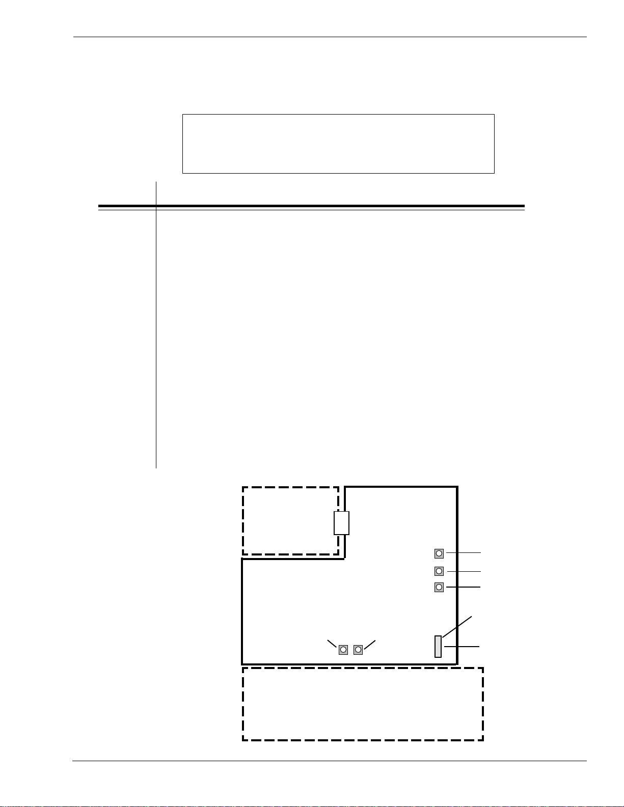
Section 4. Electric Checks and Adjustments
4.3 DC Power Voltage Checks
To check voltage levels, first check the fuses (Section 6.3) and replace if necessary. Then
remove the LH cover, (Section 4.2) and perform the following steps.
Addtional equipment required: TP Test Module
Digital Multimeter
STEP PROCEDURE
Refer to illustrations on pages 4-3 through 4-5.
1. Attach the connector from the TP Test Module to the test port on
the main PCB. Note correct positioning of connector. Nibs on the
connector are placed down in the receptacle on the PCB in the
forward position.
2. Attach the ground probe of the multimeter to the TP Test Module
Gnd pin.
3. Attach the positive probe of the multimeter to the +SIG pin on
the TP Test Module terminal.
4. Turn printer on and rotate the dial to a dial POS on the TP Test
Module. Record the values from the Multimeter LCD.
5. Confirm voltages are correct. If not, then replace power supply.
Refer to Section 6.4.
6. After performing tests, replace the LH cover to the printer.
INTERFACE
BOARD
VR5 IM
VR4 GAP
MAIN PCB
VR1 OFS
TEST POINT
VR2 DEM
VR3 CE
CONNECTOR
CN13
PN 9001078
Rev. B
POWER SUPPLY
SA TO CL408e/CL412e Service Manual
Page 4-3
Page 78

Section 4. Electric Checks and Adjustments
3
3
3
3
3
3
3
3
3
3
3
3
3
3
3
3
3
3
3
3
3
3
3
3
3
3
3
3
3
3
3
3
3
3
3
3
3
3
3
3
3
3
3
3
3
3
3
3
3
3
3
3
3
3
3
3
3
3
3
3
3
3
3
3
3
4
4
4
4
4
4
DC Power Voltage Checks
CONNECT TP TEST
MODULE TO PCB
TEST POINT @
CN13
MAIN PCB
TP TEST
MODULE
Page 4-4
TP TEST MODULE
TO PCB TEST
POINT @ CN13
23
23
23
23
23
23
CORRECT POSITION
CONNECTOR
RECEPT ACLE ON
OF NIBS ON
CONNECTOR
PCB @ CN13
SA TO CL408e/CL412e Service Manual
234567890123456789012
234567890123456789012
234567890123456789012
234567890123456789012
234567890123456789012
234567890123456789012
234567890123456789012
234567890123456789012
234567890123456789012
2
234567890123456789012
2
234567890123456789012
234567890123456789012
234567890123456789012
234567890123456789012
234567890123456789012
234567890123456789012
234567890123456789012
234567890123456789012
234567890123456789012
234567890123456789012
234567890123456789012
234567890123456789012
234567890123456789012
234567890123456789012
234567890123456789012
234567890123456789012
234567890123456789012
234567890123456789012
234567890123456789012
234567890123456789012
234567890123456789012
234567890123456789012
234567890123456789012
234567890123456789012
234567890123456789012
234567890123456789012
234567890123456789012
234567890123456789012
234567890123456789012
234567890123456789012
234567890123456789012
234567890123456789012
234567890123456789012
234567890123456789012
234567890123456789012
234567890123456789012
234567890123456789012
234567890123456789012
234567890123456789012
234567890123456789012
2
234567890123456789012
2
234567890123456789012
234567890123456789012
234567890123456789012
234567890123456789012
234567890123456789012
234567890123456789012
234567890123456789012
234567890123456789012
234567890123456789012
234567890123456789012
TP TEST
MODULE
CONNECTOR
PN 9001078
Rev. B
Page 79

DC Power Voltage Checks
CABLE TO PCB
DIAL
Section 4. Electric Checks and Adjustments
LCD DISPLA Y
PROBES
COM
GROUND
PIN
TP TEST MODULE
GND
A1
SIG PIN
VOLT
DIGITAL
MULTIMETER
SOPlaiDCSIDEGNAREGATLOVELUDOMTSETPT
GS
CN
0V5+V2.5+ot8.4+)DNG(1AHC-)V5+(3AHC
1V0.2+V1.2+ot09.1+)DNG(1AHC-)V0.2+(4AHC
2V3.3+V5.3+otV1.3+)DNG(1AHC-)V3.3+(5AHC
3V42+V5.42+otV5.32+)DNG(1AHC-)V42+(6AHC
TEST POINT CHART
B1
PN 9001078
Rev. B
+5V
+2.0V
+3.3V
+24V
A6
NOTE: The power supply voltages are not
adjustable. All voltages must read within +/10% of the nominal value for correct operation
of the printer.
B6
SA TO CL408e/CL412e Service Manual
Page 4-5
Page 80

Section 4. Electric Checks and Adjustments
4.4 Potentiometer Assignments & Adjustments
tsujdAotRVMETILAIDNOITISOP
V50
V423
1RVTESFFOHCTIP
4RVPAG5
5RVKRAM-EYE4
2RV
3RV
desUtoN
MED
desUtoN
EC
DESUTON
e214/e804LCnO
DESUTON
e214/e804LCnO
POTENTIOMETERS ARE
LOCA TED ON MAIN PCB
tsujdAotRVMETI
1RVTNIRP
2RVTESFFO
3RVHCTIP
ekaTlebaL
rosneS
resnepsiD
POTENTIOMETERS ARE
LOCA TED ON FRONT PANEL
Page 4-6
SA TO CL408e/CL412e Service Manual
PN 9001078
Rev. B
Page 81

Section 4. Electric Checks and Adjustments
Potentiometer Assignments & Adjustments
PN 9001078
Rev. B
INTERF ACE
BOARD
MAIN PCB
VR2 DEM
VR3 CE
POWER SUPPLY
SA TO CL408e/CL412e Service Manual
VR5 IM
VR4 GAP
VR1 OFS
TEST POINT
CONNECTOR
CN13
Page 4-7
Page 82

Section 4. Electric Checks and Adjustments
4.5a Print Position Adjustment
Print Position is adjusted with the Pitch potentiometer on the Front Panel or VR1
potentiometer on the main PCB board to change print position.
The following instructions are for adjusting the potentiometer on the Front Panel. Refer to
Section 4.5b for making adjustments using the potentiometer on the PCB board.
Note: The print position can be
changed with the PITCH-VR but
the stop position cannot be
PITCH-VR
STEP PROCEDURE
1. Open the Front Door for access to Pitch-VR.
changed. The stop position can
be changed with the OFFSET VR.
PITCH-VR adjustment range is
+/- 3.75mm.
2. Turn Pitch-VR to the center position.
3. Press the FEED key while simultaneously turning ON the power switch.
4. When the printer beeps, release the key. The following screens will appear.
initializing
rom v00.00.00.00
5. Press the FEED key to display the next screen.
test print mode
configuration
test print size
10cm
6. Use the LINE Key to step to the second digit of the counter to the desired
setting. The display will increment one step each time the LINE key is
pressed. After the reading will advances to a setting of 09, it will
automatically wrap and start at 10 CM again.
7. Press the FEED key for a test print. Press the FEED key again to stop
printing.
press feed key
Page 4-8
to stop printing
8. Adjust the position using the potentiometer and feed another label. When
the adjustment is correct, turn the printer off. If the print position can't be
adjusted replace the Display Panel PCB. Refer to Section 6.
SA TO CL408e/CL412e Service Manual
PN 9001078
Rev. B
Page 83

4.5b Print Position Adjustment
Section 4. Electric Checks and Adjustments
Using the VR1 potentiometer on the main PCB board.
STEP PROCEDURE
VR1 adjustment range is
+/- 3.75mm.
Refer to Section 4.2 for access to main PCB
1. Record all current dip switch positions, then place all switches in the OFF
position and the power switch OFF.
2. Turn VR1 on the main PC Board to the center position.
3. Place DSW2-4 in the ON (up) position.
4. Press the LINE and FEED key while simultaneously turning the power
switch ON.
5. When the printer beeps, release the keys. The following screens will appear.
initializing
rom v00.00.00.00
6. Place DSW2-4 in the OFF (down) position and the screen will display the
next screen.
maintentance mode
dipsw2-4 on->Off
factory mode
7. Press the FEED key to display the next screen.
counter clear
none
8. Confirm "None" then press the FEED key to display the next screen.
print size
small large
The default is Large.
9. Press the FEED key for a test print. Press the FEED key again to stop
printing.
test print
press the feed key
10. Adjust the position using the VR1 potentiometer and feed another label.
When the adjustment is correct, turn the printer off. If the print position
can't be adjusted with the VR1, replace the Main PCB. Refer to Section 6.
PN 9001078
Rev. B
SA TO CL408e/CL412e Service Manual
Page 4-9
Page 84

Section 4. Electric Checks and Adjustments
4.6 Label Gap Adjustment
Additional equipment required: TP Test Module
STEP PROCEDURE
Refer to Section 4.2 for access to main PCB
1. Turn VR4 (GAP) potentiometer on the main PCB all the way to the
left.
2. Refer to Section 4.3.
Set the digital multimeter to DC voltage measurement mode.
Attach the connector from the TP Test Module to the test port on the
main PCB. Note correct positioning of connector. Nibs on the connector
are placed down in the receptacle on the PCB in the forward position.
Set the dial to 5.
Digital Multimeter
3. Connect (+) probe of the multimeter to Sig+ and (-) probe to pin
GND.
4. For Low level (Label Gap part with backing only) adjustment, put label
gap part in the sensor. Then adjust the electrical level with VR4 on the
main PCB so that it will measure less than 0.5 V.
5. For High level (paper part) adjustment, put paper part in the sensor
and check the electrical level. If the level difference is +1.0 V more
than the Low level, it is acceptable. If it is lower than 1.0V repeat
STEPS 4 & 5 and readjust VR4.
6. Standard values: Low level (gap): below 0.5 V
High level (paper part): Low level +1.0 V or
higher. If these values do not result, try the
following:
a) Repeat the process
b) Clean the sensor
c) Verify sensor is operational
Page 4-10
d) Replace labels with higher quality labels
e) Perform factory reset
SA TO CL408e/CL412e Service Manual
PN 9001078
Rev. B
Page 85

4.7 Eye-Mark Adjustment
Additional equipment required: TP Test Module
STEP PROCEDURE
Refer to Section 4.2 for access to main PCB
1. Turn VR5 (IM) potentiometer on the main PCB all the way to the left.
2. Refer to Section 4.3.
Set the digital multimeter to DC voltage measurement mode.
Attach the connector from the TP Test Module to the test port on the
main PCB. Note correct positioning of connector. Nibs on the connector
are placed down in the receptacle on the PCB in the forward position.
Set the dial to 4.
Section 4. Electric Checks and Adjustments
Digital Multimeter
3. Connect (+) probe of the multimeter to Sig+ and (-) probe to pin
GND.
4. For Low level (no "Eye-Mark" part) adjustment, put paper part in the
sensor. Then adjust the electrical level with VR5 on the main PCB so
that it will measure less than 0.5 V.
5. For High level ("Eye-Mark" part) adjustment, put paper part with the
"Eye-Mark" part in the sensor and check the electrical level. If the level
difference is +1.0 V more than the Low level, it is acceptable. If not,
return to STEP 4 and readjust VR5.
6. Standard values: Low level (no "Eye-Mark" part): +0.5 V or less.
High level ("Eye-Mark"): Low level +1.0 V or
higher. If these values do not result, try the
following:
a) Repeat the process
b) Clean the sensor
c) Verify sensor is operational
PN 9001078
Rev. B
d) Replace labels with higher quality labels
e) Perform factory reset
SA TO CL408e/CL412e Service Manual
Page 4-11
Page 86

Section 4. Electric Checks and Adjustments
4.8 Offset Label Stop Position Adjustment
Used for fine adjustment of label stop position for Tear Off, Cutter and Dispense Modes.
The Label Stop Position is adjusted with the Offset potentiometer on the Front Panel.
Note: The stop position only is
changed with the Offset-VR.
The print position is changed with
OFFSET-VR
STEP PROCEDURE
the Pitch-VR.
The OFFSET-VR adjustment range
is +/- 3.75mm.
1. Open the Front Door for access to Offset-VR.
2. Turn Offset-VR to the center position.
3. Press the FEED key while simultaneously turning ON the power switch.
4. When the printer beeps, release the key. The following screens will appear.
initializing
rom v00.00.00.00
5. Press the FEED key to display the next screen.
test print mode
configuration
test print size
10cm
6. Use the LINE Key to step to the second digit of the counter to the desired
setting. The display will increment one step each time the LINE key is
pressed. After the reading will advances to a setting of 09, it will
automatically wrap and start at 10 CM again.
7. Press the FEED key for a test print. Press the FEED key again to stop
8. Adjust stop the position using the Offset-VR and feed another label. When the
Page 4-12
printing.
press feed key
to stop printing
adjustment is correct, turn the printer off. If the print position can't be
adjusted replace the Display Panel PCB. Refer to Section 6.
SA TO CL408e/CL412e Service Manual
PN 9001078
Rev. B
Page 87

Section 4. Electric Checks and Adjustments
4.9a Ribbon Sensor Operation Verification
No adjustment is provided
for this sensor
SEE PAGE 1-6 FOR
PLACE DSW2-1 IN
THE OFF POSITION
STEP PROCEDURE
1. Open the Front Door for access to DIP Switches.
2. Record all dip switch positions, then place DSW2-1 in the OFF position and
the power switch OFF.
3. Remove the ribbon from the printer and close the Head Open Lever.
SENSOR LOCA TION
4. Turn the power switch ON to initialize the printer. The following screens will
display.
initializing
rom v00.00.00.00
5. Press the LINE key to place the printer off-line.
6. Press the FEED key. The printer will beep and the following screen will
display to confirm that the ribbon is not in position and confirm the sensor is
functioning.
online
qty:000000
Ribbon end
7. Turn off the printer and reinstall the ribbon.
8. Turn ON the printer. The printer will initialize as in Step 4. Be sure to place
the printer off line. Press the FEED key to generate a blank label and
confirm ribbon has been installed and is in position.
PN 9001078
Rev. B
SA TO CL408e/CL412e Service Manual
Page 4-13
Page 88

Section 4. Electric Checks and Adjustments
4.9b Ribbon Sensor Voltage Checking
There is no adjustment POT for the ribbon sensor on the CL408e/412e. The CE POT on
the main logic board has no effect on the voltage values. The voltage values only can be
taken off the connector SEN4 on the display.
Refer to illustrations below.
PIN 1 = Brown
PIN 2 = Red
PIN 3 = Orange
PIN 4 = Yellow
PIN 3 (Signal) and PIN 4 (Ground) are the test pins. Low value when the carbon assembly
is rotated is around 0.16V. High value is around 4.8V.
If the voltages you monitor are at or close to these voltages, the ribbon out problem is
being caused by improper ribbon tension adjustment.
If the voltages are not at or close to these values, it indicates a component problem. The
order suggested for component replacement trouble shooting is ribbon sensor first, display
panel next, and finally the main logic board.
PULL SEN4 CONNECTOR
SLIGHTL Y A W A Y FROM
DISPLAY PANEL
CONNECTIOR SO THAT
VOLTAGE PROBES CAN BE
ATTACHED TO THE
EXPOSED PINS
Page 4-14
SA TO CL408e/CL412e Service Manual
PN 9001078
Rev. B
Page 89

Ribbon Sensor Voltage Checking
ATTACH THE GROUND
(BLACK) PROBE FROM
THE MULTIMETER TO PIN 4
(GROUND) AND THE
SIGNAL (WHITE) PROBE TO
PIN 3
Section 4. Electric Checks and Adjustments
TO CHECK VOLTAGE RANGE FOR
RIBBON SENSOR, ROTATE CARBON
UNWIND SPINDLE.
LOW V ALUE ~/- 1.6V
HIGH V ALUE ~/- 4.8V
PN 9001078
Rev. B
SA TO CL408e/CL412e Service Manual
Page 4-15
Page 90

Section 4. Electric Checks and Adjustments
4.10 Print Darkness Adjustment
STEP PROCEDURE
1. Open the Front Door for access to Pitch Potentiometer.
2. Turn the power switch ON.
3. Send print data from your PC and confirm the result.
ADJUST PITCH
POTENTIOMETER
FOR OPTIMUM
PRINT
4. Adjust the Pitch Potentiometer to obtain optimum print quality. If
quality is still lacking, refer to Section 2 Configuration, Print Darkness
Setting, page 2-9.
Page 4-16
SA TO CL408e/CL412e Service Manual
PN 9001078
Rev. B
Page 91

Section
Mechanical Adjustments
#
5.1 Overview
The SATO CL408e/CL412e contain adjustable sub-assemblies. This means that during
your regular maintenance, your service technicians are able to make adjustments to reset
the printer to factory specifications therby ensuring optimum performance of your printer
The main mechnaical sub-assemblies are:
• Ribbon Unwind/Rewind Assembly's
• Ribbon Guide Roller Assembly
• Print Head Assembly
• Drive Belt Assembly
In this section you will find procedures for:
• Ribbon Clutch Adjustments
• Ribbon Guide Plate Adjustment
• Tear Plate Adjustment
• Print Head Position Alignment
• Print Head Balance Adjustment
• Print Head Alignment Adjustment
• Timing Belt Tension Adjustment
Checks and adjustments in this section require standard metric tools.
Other equipment is listed where needed.
PN 9001078
Rev. B
SA T O CL408e/CL412e Service Manual
Page 5-1
Page 92

Section 5. Mechanical Adjustments
5.2 Ribbon Clutch Adjustments
Excessive ribbon and rewind tension will result in variable ribbon motion and could be the
cause of print quality problems.
Follow the procedures 5.2.1 and 5.2.2 to verify that the ribbon rewind and unwind tensions
are within specifications or if adjustment of either clutch is necessary.
Required Equipment: 1 Kg Tension Gauge
Ribbon Core, empty
String
12mm Wrench
#2 Pozidrv Screwdriver
5.2.1 Ribbon Rewind Clutch Adjustment
STEP PROCEDURE
1. Switch the printer OFF and disconnect the power cable.
2. Raise the top access door and open the front access door. Remove the ribbon
and label stock if installed. Fig. 5-1
3. Attach string to an empty ribbon core and place on the Ribbon Rewind
Spindle. Wind the string tightly around the ribbon core in a single layer and in
in clockwise direction. Attach the free end of the string to the tension gauge.
Fig. 5-2
4. Gradually lift the tension gauge, pulling the string to unwind it from the core.
Once the spindle gegins to move, the gauge should indicate 950 to 1050
grams of tension. Excessive or insufficient tension must be corrected by
adjusting the Ribbon Rewind Clutch.
5. To adjust the clutch, loosen the locking screw and move the adjust nut CW for
more tension and CCW for less tension. Tighten the locking screw and repeat
steps 3 and 4 until the correct tension is achieved.
RAISE THE TOP
ACCESS DOOR
Page 5-2
OPEN THE FRONT
ACCESS DOOR
Fig. 5-1
SA T O CL408e/CL412e Service Manual
PN 9001078
Rev. B
Page 93
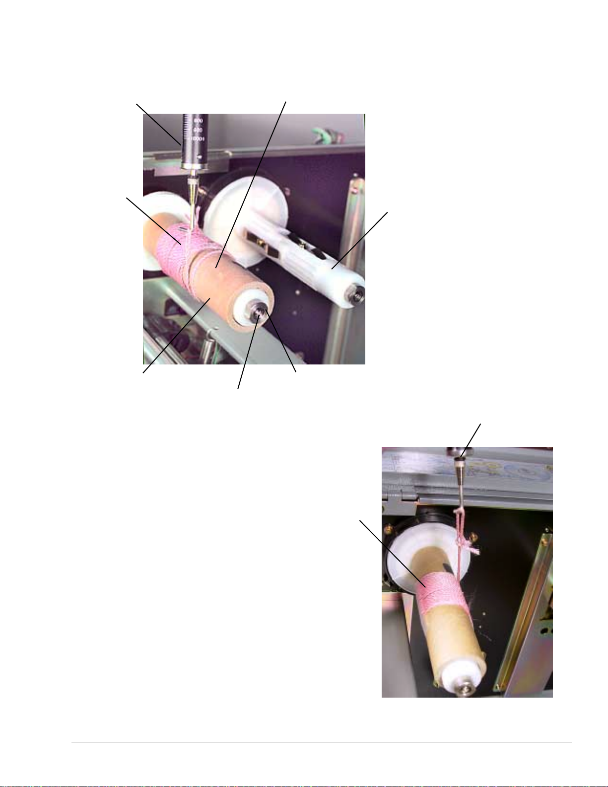
Ribbon Clutch Adjustments
TENSION GAUGE
STRING
Section 5. Mechanical Adjustments
950-1050g
REWIND
RIBBON
UNWIND
SPINDLE
EMPTY RIBBON
CORE
Fig. 5-2
ADJUST NUT
LOCKING SCREW IS
INSIDE ADJUST NUT
REWIND CLUTCH
TENSION GAUGE
450-550g
UNWIND
PN 9001078
B
Rev. A
Fig. 5-3
SA T O CL408e/CL412e Service Manual
UNWIND CLUTCH
Page 5-3
Page 94

Section 5. Mechanical Adjustments
Ribbon Clutch Adjustments
5.2.2 Ribbon Unwind Clutch Adjustment
STEP PROCEDURE
1. Switch the printer OFF and disconnect the power cable.
2. Raise the top access door and open the front access door. Remove the ribbon
and label stock if installed. Fig. 5-1
3. Attach string to an empty ribbon core and place on the Ribbon Unwind
Spindle. Wind the string tightly around the ribbon core in a single layer and in
in counter-clockwise direction. Attach the free end of the string to the tension
gauge. Fig. 5-3
4. Gradually lift the tension gauge, pulling the string to unwind it from the core.
Once the spindle begins to move, the gauge should indicate 450 to 550 grams
of tension. Excessive or insufficient tension must be corrected by adjusting
the Ribbon Unwind Clutch.
5. To adjust the clutch, loosen the locking screw and move the adjust nut CW for
more tension and CCW for less tension. Tighten the locking screw and repeat
steps 3 and 4 until the correct tension is achieved.
Page 5-4
SA T O CL408e/CL412e Service Manual
PN 9001078
Rev. A
B
Page 95

Section 5. Mechanical Adjustments
5.3 Ribbon Guide Plate Adjustment
If the ribbon is not smooth across the guide plate (ribbon wrinkle) adjustment is required.
To remedy the problem perform the Print Head Balance Adjustment (Section 5.6) before
doing the Ribbon Guide Plate Adjustment.
Required Equipment: #2 Pozidrv Screwdriver
STEP PROCEDURE
1. Check for even ribbon tension by watching the ribbon movement under the
guide plate as it moves upward toward the ribbon rewind spindle. If it
appears uneven, proceed to next step.
2. Loosen the mounting screws and reposition the plate. Fig. 5-4
3. Tighten the mounting screws.
GUIDE PLA TE
MOUNTING
SCREWS
Fig. 5-4
PN 9001078
Rev. B
SA T O CL408e/CL412e Service Manual
Page 5-5
Page 96

Section 5. Mechanical Adjustments
5.4 Tear Plate Adjustment
Required Equipment: #2 Pozidrv Screwdriver
STEP PROCEDURE
1. Loosen the Tear Plate mounting screws and position plate so that the lip is
parallel to the bottom of the printer assembly. Figs. 5-5
2. Tighten the mounting screws.
LIP
MOUNTING SCREWS
LIP TO BE PARALLEL
WITH BOTTOM
SURFACE
Page 5-6
Figs. 5-5
SA T O CL408e/CL412e Service Manual
PN 9001078
Rev. B
Page 97

Section 5. Mechanical Adjustments
5.5 Print Head Position Alignment
MINOR ADJUSTMENT
Required Equipment: 10mm Open End Wrench
#2 Pozidrv Screwdriver
To adjust the print head alignment and make print quality consistent across
label, perform the following steps:
STEP PROCEDURE
1. Loosen the center and right screw on the ribbon adjustment plate. Print a user
test pattern (Section 8.9). Realign the right side of print head by prying adjust
plate forward or backward with a flat blade screwdriver. Refer to illustrations
and note adjustment marks. Figs. 5-6
2. Tighten the screws.
RIBBON ADJUST
PLATE
ADJUSTMENT
MARKS
SCREWS
Figs. 5-6
PN 9001078
Rev. B
SA T O CL408e/CL412e Service Manual
Page 5-7
Page 98

Section 5. Mechanical Adjustments
5.6 Print Head Balance Adjustment
Required Equipment: 10mm Open End Wrench
#2 Pozidrv Screwdriver
To optimize print quality, perform the following steps to adjust the Print Head Balance
using head pattern as a guide. Proper adjustment is necessary to avoid ribbon wrinkle.
STEP PROCEDURE
1. Load the ribbon and label stock into the printer.
2. Hold eccentric nut along flats with 10mm box wrench and loosen holding screw.
Fig. 5-7
3. Adjust eccentric nut by rotating CW or CCW.
Rotating CW increases print density on left side of label. CCW decreases print
density on the right side of label. Note indexing marks on plate. Allowable
range is between 7-11 o'clock.
4. Tighten screw to secure eccentric nut in place.
5. Loosen and adjust screw along slot to move indexing pointer for maximum print
quality.
LOOSEN SCREW
1/4 TURN
Page 5-8
Fig. 5-7
INDEXING
MARKS
USE 10mm BOX WRENCH
TO ADJUST ECCENTRIC
NUT CW OR CCW AND
TIGHTEN SCREW
SA T O CL408e/CL412e Service Manual
PN 9001078
Rev. B
Page 99

Section 5. Mechanical Adjustments
5.7 Print Head Alignment Adjustment
MAJOR ADJUSTMENT
Required Equipment: #2 Pozidrv Screwdriver
To further optimize print quality, especially when using thick label stock, additional
adjustments are possible. Perform the following steps using head pattern as a guide.
STEP PROCEDURE
1. Load the ribbon and label stock into the printer.
2. Loosen and adjust screw along slot to move indexing pointer for maximum
print quality. Fig. 5-8
Fig. 5-8
INDEXING POINTER
SHIFTS HEAD
BACKWARD/FORWARD
PN 9001078
Rev. B
SA T O CL408e/CL412e Service Manual
Page 5-9
Page 100

Section 5. Mechanical Adjustments
5.8 Timing Belt Tension Adjustment
Required Equipment: 1 Kg Tension Gauge
#2 Pozidrv Screwdriver
To adjust the Timing Belt Tension, perform the following steps:
STEP PROCEDURE
1. Press in the center of each timing belt with the tension gauge and note the
tension reading when the belt is moved 1 to 2mm.
2. If the tension reading of each belt is not within range of 80 - 120g, adjust the
position of the pulley by loosening the (4) stepper motor mounting screws and
moving motor to achieve the required range. After adjusting motor, tighten but
do not over tighten screws. Belts should have some movement. Fig. 5-9
TIMING BELTS
MOTOR
MOUNTING
SCREWS
Fig. 5-9
Page 5-10
SA T O CL408e/CL412e Service Manual
PN 9001078
Rev. B
 Loading...