

SARGENT FM8700 User Manual
U.S. Patent No. 268,003
C
INSTALLATION INSTRUCTIONS
anadian Patent No. RD 1981
FM8700, 12-FM8700 Surface Vertical Rod Exit Device
FOR INSTALLATION ASSISTANCE, CALL SARGENT AT 1-800-727-5477 • www.sargentlock.com
NOTE:THIS DEVICE IS ONE COMPONENT OF A SPECIFIC COMBINATION
OF HARDWARE REQUIRED FOR THIS OPENING TO MEET FEMA 361
REQUIREMENTS. FOLLOW ALL INSTALLATION STEPS AS DIRECTED,
IN SEQUENCE GIVEN.
NOTE: FOR 12-FM8700 SINGLE DOOR APPLICATION, (4) THERMAL PINS
ARE REQUIRED. SEE TEMPLATE 4628, PG. 4.
Rail Lengths & Cutting Instructions, Pg.4.
TOOLS REQUIRED
• Power drill, drill bits #7, #16, #25, 3/32",
1/4", 11/32", 3/8", 25/64", and 3/4"
• Taps, #10-24, #12-24, 1/4"-20, 7/16"-20
• Hacksaw or power cutter
Screwdrivers, Phillips #2, #3
•
• Allen wrenches, 1/8", 3/16", 5/16", 3/8"
• Level, Pencil, Tape Measure
1
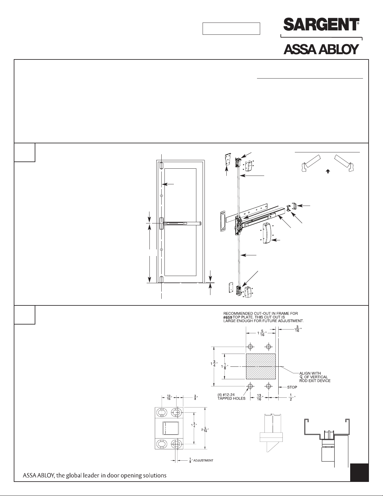
1. MARK VERTICAL REFERENCE
LINE A.
A is CENTERLINE for chassis,
top and bottom cases
2. MARK HORIZONTAL REFERENCE
LINE B at
41" above finished floor.
B is CENTERLINE for
chassis and rail
3. TAPE TOP CASE AND CHASSIS
TEMPLATES TO DOOR (PACKED
WITH DEVICE)
2
INSTALL TOP BOLT AND STRIKE
“B”
41"
“A”
Inside
face of
d
oor
Interlocking
shim
5/8"
Max
Finished floor
Top case
Bottom rod
Bottom case
op rod
T
Chassis
Push rail assembly
Chassis cover
THIS EXIT DEVICE IS HANDED
OUT
R
ight hand
r
everse bevel
End cap bracket
End cap
Left hand
reverse bevel
PREPARE CUT-OUT IN FRAME FOR
659 TOP BOLT / STRIKE
Use 11/64" drill, 12-24 tap, #3 Phillips screwdriver.
INSTALL 659 TOP BOLT/STRIKE
Transfer vertical centerline to door frame. With
the door closed, align INTERLOCKING SHIM
with 659 TOP BOLT/STRIKE and place on vertical
reference line. Mark and drill 4 mounting holes
using 11/64" drill and 12-24 tap.
MOUNT 659 TOP BOLT/STRIKE, (4)
#12-24 x 3/4" PH.FL.HD.Mach. Screws
NOTE: ALL FOUR FASTENERS
REQUIRED. DO NOT TIGHTEN UNTIL STEP 4
#659 Top Plate
Copyright © 2006-2010, Sargent Manufacturing Company,an ASSA ABLOYGroup
company.All rights reserved. Reproductionin whole or in part without the express
written permissionof Sargent Manufacturing Company is prohibited.
Frame Cutout
Top Bolt
Top bolt assembly in
frame, cut-away view
A7827D 3-10-10
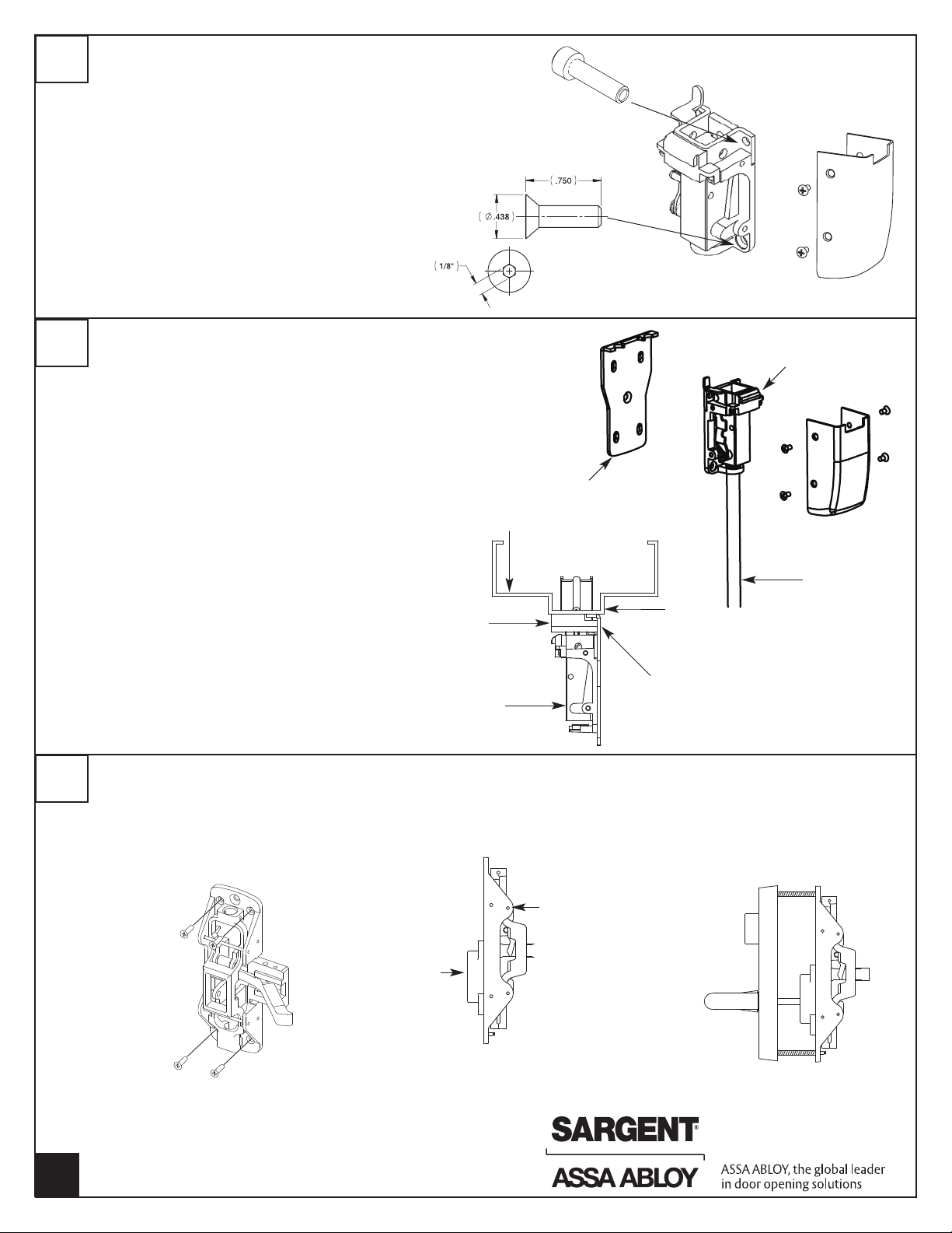
1
3
INSTALL TOP CASE
Top Chassis Assembly
With the door closed center the TOP CHASSIS ASSEMBLY
and INTERLOCKING SHIM on vertical reference line.
Ensure INTERLOCKING SHIM is engaged in TOP
BOLT/STRIKE
Mark location of (4) mounting screws
USE 3/8" DRILL BIT to drill two TOP MOUNTING HOLES
THROUGH DOOR. Install (2) sex nuts, p/n 60-0502 from
OUTSIDE door surface. Install (2)
-12-24 x 3/4 Socket Head Cap Screws from INSIDE.
ATTACH USING (2) 12-24 x 3/4" flat head socket head
screws in two BOTTOM mounting holes (1/8" Allen
wrench).
4
SECURING INTERLOCKING SHIM
With the TOP CHASSIS ASSEMBLY and INTERLOCKING SHIM
secured, the 659 TOP BOLT/STRIKE should engage the TOP
CHASSIS ASSEMBLY and INTERLOCKING SHIM when door
is closed.
Trace the outline of the INTERLOCKING SHIM
Remove the TOP CHASSIS ASSEMBLY to expose the center
hole on the INTERLOCKING SHIM. Ensure the INTERLOCKING
SHIM is aligned with the tracing. Mark and tap center hole (1)
12-24 x ¾” flat head socket head screw.
REINSTALL TOP CHASSIS ASSEMBLY.
Check for TOP CHASSIS ASSEMBLY and 659 TOP
BOLT/STRIKE engagement. Tighten all screws.
INSTALL TOP CASE COVER using (4) 8-32 x 5/16” screws
(2) 12-24 x 3/4"
Socket Head Cap
Screws
(2) 12-24 x 3/4" Flat Head
S
Door Frame
Top Plate
ocket Screws
Interlocking
Shim
Top case
Top rod
Door Stop
5
INSTALL CENTER CHASSIS
SECURE CHASSIS and CHASSIS SHIM with
(4) #10-24 x 3/4" PH.FL.HD.Mach. Screws, 4
corner mounting holes.
NOTE: USE ALL FOUR SCREWS PROVIDED.
Bell housing
op Case
T
POSITION TRIM ON
DOOR - Align spindle
with BELL HOUSING
Chassis
Interlock Shim
THRU-BOLT CHASSIS
to ET TRIM with
(2) 1/4"-20 x 2 3/8"
PH.FL.HD.Mach. Screws
2
A7827D 3-10-10
Copyright © 2006-2010, Sargent Manufacturing Company,an ASSA ABLOYGroup
company.All rights reserved. Reproductionin whole or in part without the express
written permissionof Sargent Manufacturing Company is prohibited.
 Loading...