

Sargent Fireguard 2900 Series,Fireguard 12-2960,Fireguard 9-2960,Fireguard 2960 Installation Instructions Manual
2900 FIREGUARD® Electromechanical Closer-Holder Device Models
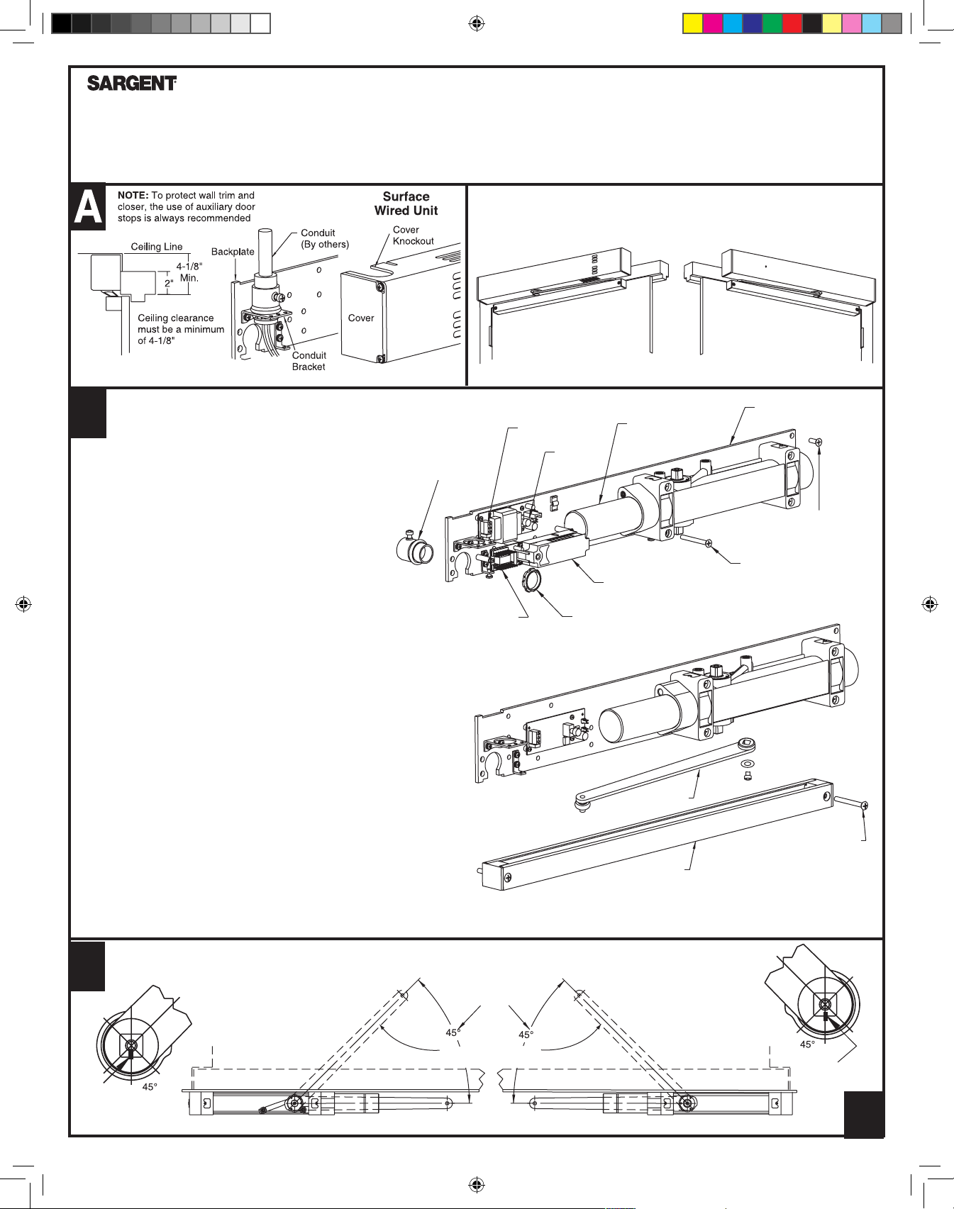
B
NOTE:
12-2960, 9-2960 and 2960 Multipoint Hold Open with Rigid Arms
Pull (Hinge) Side Installation Instructions
CAUTION: FAILURE TO INSTALL OR ADJUST PROPERLY MAY RESULT IN INJURY OR DAMAGE
For assistance, contact SARGENT at 800-810-WIRE (9473) or www.sargentlock.com
FOR MODELS 12-2960 / 9-2960 / 2960
1. Use dimensions shown on page 5 provided to locate
attaching screws on frame and door. Prepare holes
For concealed wire applications only
Locate and drill 1-1/8" diameter hole in the frame face for
3/4" conduit. (This is normally done at the time the frame
is being installed.) Connect conduit to backplate before
fastening backplate to frame
2. Attach backplate/closer assembly to frame. Position backplate
end with terminal strips away from hinge edge of frame
3. Make electrical connections:
A) 12-2960: Select and follow the wiring diagram from wiring
instructions sheet A7408 and 'Checkout Procedure' from Page 3.
B) 9-2960: Make solenoid wire connections with power input wires
from 12-2960 using two wire nuts provided in screw pack. Select
proper wiring diagram and 'Checkout Procedure' from Page 3.
4. Make input power connections to the power supply board as directed.
NOTE: If electrical connections are to be made at a later date,
place cover on chassis now to prevent its loss, see Step F.
3/4" Conduit
(By others)
MODEL
12-2960
RH - Right Hand Door
LHR - Left hand Reverse
Terminal
Strips
On/Off
Switch
Terminal
Strips
Devices are handed
and must be the same
hand as door.
Closer/Holder
Smoke
Detector
Conduit Nut
(By others)
12-2960
MODELS
2960/9-2960
LH - Left Hand Door
RHR - Right Hand Reverse
Backplate
Backplate
Screw (6)
Closer
Screw (4)
5. Installation of arm on closer: With appropriate size wrench, rotate
closer top spindle approximately 45ϒ (see step C below) (NOTE:
Closing both valves for door speed and latching speed makes this
procedure much easier). Position closer arm on bottom spindle
approximately parallel to the door and arm length away from hinge.
Secure arm with screw and washer
6. Installation of track on door: Remove end cap from track. Position
track with open side up. Insert roller end of closer arm in sliding
groove of track. With arm engaged in slide groove, slide track, into
position so that prepared holes on door align with track holes
Replace end cap and secure track to door
Companion unit (without electronics) not shown
Position of Arms and Index Settings
C
View Looking Up When
Assembling Arm to Spindle
Index
Mark on
Spindle
Right Hand Door
2960
9-2960
Approximate
Preload
Position of Main Arm
When Assembled to Spindle
Rigid Arm
Track
View Looking Up When
Assembling Arm to Spindle
Left Hand Door
Track Screw
(2 Reqd)
Index
Mark on
Spindle
A7395C
1
A7395C.indd 1 10/29/18 12:44 PM
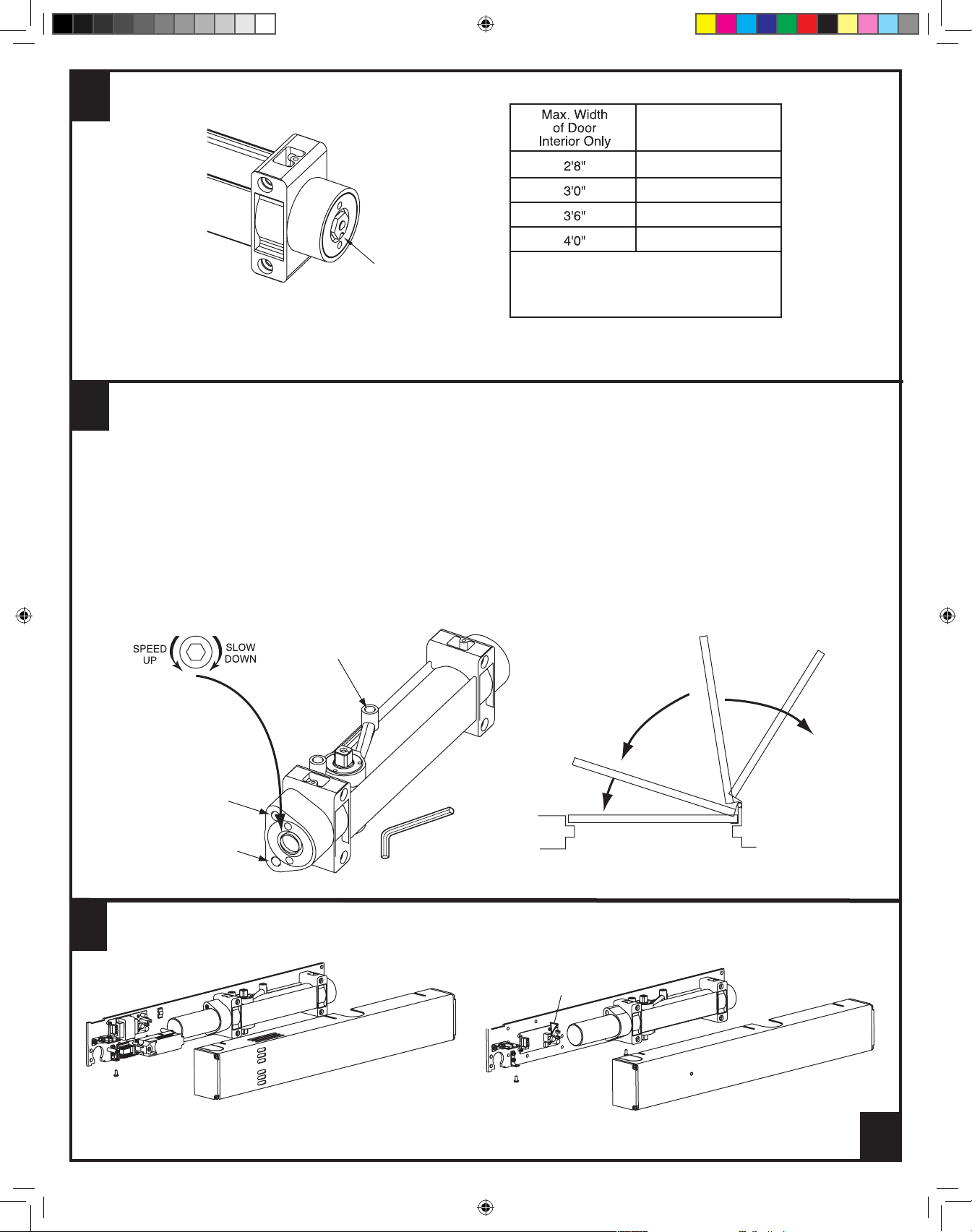
Adjust Spring Power According to Chart
D
Clockwise Turns
of Adjusting Nut
8
8
12
16
5/8 " Adjustment Nut
Tu rn the spring adjusting nut clockwise the required number of turns to match door width as indicated in chart. Where strong drafts exist, increase spring power
as needed. 351 Series door closers leave the factory with the spring adjustment set at eight (8) turns
Maximum adjustment is
approximately 20 turns.
Do not forcibly extend
adjustment beyond limits.
Adjustment Instructions
E
Minimum recommended door closing time is 6 seconds for doors opened to 90 degrees.
Use 1/8" hex (Allen) wrench to adjust valves as needed.
Closing and latching speeds:
Turn valves clockwise to slow down or counterclockwise to speed up door movement.
F
Backcheck:
To regulate the intensity of backcheck action, turn valve clockwise to increase or counterclockwise to decrease checking.
Caution: Set valve for slight cushioning effect. Closer can be damaged if the checking action is too abrupt. Never use the backcheck
as a door stop. Always use a door stop to stop the door.
Backcheck
valve
CLOSING SPEED
RANGE
Closing
speed
valve
Latching
speed
valve
To Install Cover
Adjust closers as directed
in steps D and E
LATCHING SPEED
1/8” HEX SOCKET
WRENCH
1. Assemble (3) short cover screws
(#8-32 x 5/16") into bottom of
closer body and cover mounting
bracket, approx. one turn
RANGE
2. Slide cover onto backplate and
closer assembly. Secure with
three cover screws
BACKCHECK
RANGE
12-2960
CAUTION: Avoid
interference with
electronics and wires
during installation of cover
A7395C.indd 2 10/29/18 12:44 PM
9-2960 Without Electronics not shown
On/Off
Switch
2960
A7395C
2
 Loading...