

Sargent EK Exit Device Retrofit Kit,Passport 1000 Installation Instructions Manual
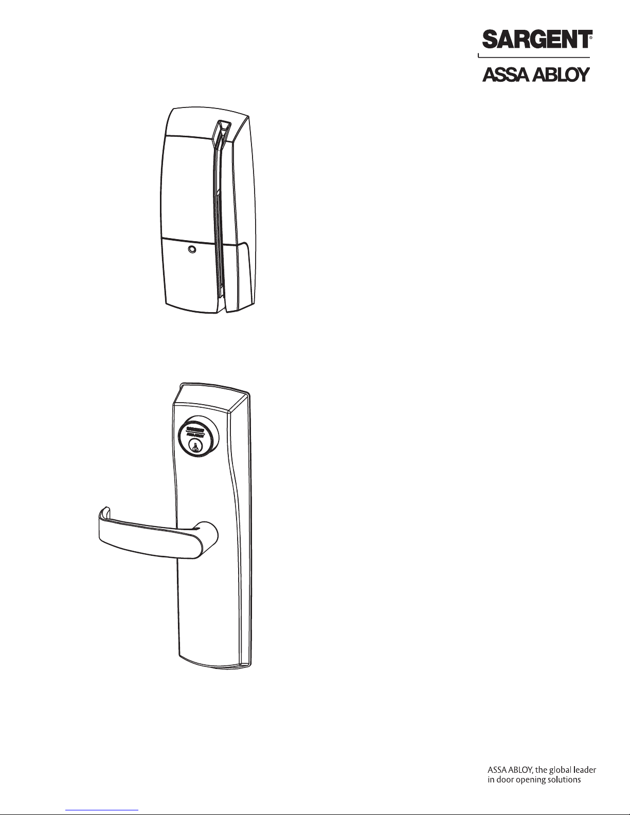
EK Exit Device
Retrofit Kit
for
Passport 1000
Installation Instructions
A8112C
04/16
Copyright © 2016, Sargent Manufacturing Company, an ASSA ABLOY Group company.
All rights reserved. Reproduction in whole or in part without the express written permission
of Sargent Manufacturing Company is prohibited.

Table of Contents
Warning ...................................................................................3
1
2
General Description .................................................................4
3
Hardware Specifications .........................................................4
4
Electronic Specifications .........................................................4
5
Installation Instructions ..........................................................5
Operational Check .................................................................23
6
1
Warning
Changes or modifications to this unit not expressly approved by the party responsible
for compliance could void the user’s authority to operate the equipment.
FCC
NOTE: This equipment has been tested and found to comply with the limits for a Class B digital device, pursuant
to Part 15 of the FCC Rules. These limits are designed to provide reasonable protection against harmful interference in a residential installation.
This equipment generates, uses, and can radiate radio frequency energy and, if not installed and used in accordance with the instructions, may cause harmful interference to radio communications. However, there is no
guarantee that interference will not occur in a particular installation. If this equipment does cause harmful interference to radio or television reception, which can be determined by turning the equipment off and on, the user is
encouraged to try to correct the interference by one or more of the following measures:
• Reorient or relocate the receiving antenna.
• Increase the separation between the equipment and receiver.
• Connect the equipment into an outlet on a circuit different from that to which the receiver is connected.
• Consult the dealer or an experienced radio/TV technician for help.
Industry Canada:
Statement: The term “IC:” before the radio certification number only signifies that Industry Canada
technical specifications were met.
This Class B digital apparatus meets all requirements of the Canadian Interference Causing Equipment Regulations. Operation is subject to the following two conditions: (1) this device may not cause harmful interference, and
(2) this device must accept any interference received, including interference that may cause undesired operation.
Cet appareillage numérique de la classe B répond à toutes les exigences de l’interférence canadienne
causant des règlements d’équipement. L’opération est sujette aux deux conditions suivantes: (1) ce
dispositif peut ne pas causer l’interférence nocive, et (2) ce dispositif doit accepter n’importe quelle
interférence reçue, y compris l’interférence qui peut causer l’opération peu désirée.
To comply with “Fire Listed” doors, the batteries must be replaced with alkaline batteries only.
!
Any retrofit or other field modification to a fire rated opening can potentially impact the fire rating of the opening,
and SARGENT® makes no representations or warranties concerning what such impact may be in any specific
situation. When retrofitting any portion of an existing fire rated opening, or specifying and installing a new firerated opening, please consult with a code specialist or local code official (Authority Having Jurisdiction) to ensure
Copyright © 2016, Sargent Manufacturing Company, an ASSA ABLOY Group company. All rights reserved.
Reproductions in whole or in part without express written permission of Sargent Manufacturing Company is prohibited.
04/30/16
1-800-810-WIRE • www.sargentlock.com • A8112C
compliance with all applicable codes and ratings.
Observe precautions for handling electrostatic sensitive devices.
3
EK Exit Device Retrofit Kit for Passport 1000
2
General Description
The EK Exit Device Retrofit Kit is designed to link the SARGENT Passport 1000 Series P1/P2 product line
with non-SARGENT rim exit devices. The EK Retrofit Kit is designed specifically to link to the Von Duprin®
98/99 Series rim exit device. Refer to Von Duprin Retrofit Chart (page 9) for replaceable Von Duprin exit
trim. The P1/P2 Passport locks provide access control with magnetic swipe and optional contactless
reader and/or keypad, as well as detailed audit capabilities.
For double door openings that require only a mechanical outside exit trim on one side of the opening, a
dummy trim (706-5-EK1) is available. This option ensures a consistent aesthetic across both doors.
3
Hardware Specifications
EK Exit Device Retrofit Kit for Passport 1000
• Retrofits existing Von Duprin 98/99 rim exit device. Consult the Von Duprin Retrofit Chart (page 9) for more
specific information regarding the various trims that can be replaced.
• Outside lever is unlocked through access control credentials or mechanical key override
• Accepts various rim cylinders (cylinder not included). For a partial list of cylinders by others, see table on
page 9.
• Can be used with all P1 & P2 features
• On-board memory
• RX switch required (not included)*
*Von Duprin® RX Switch Retrofit Kit (part number 050251-00) available through an authorized
Von Duprin distributor.
4
Electronic Specifications
P1
• 2,400 users per lock; 10,000 event audit trail
• Multiple time zone and holiday access scheduling
• First-In unlock configuration, either by time or by
user (selectable)
• Centralized lock management
• Real time door status monitoring
• Lockdown capable
P2
• 2,400 users per lock; 10,000 event audit trail
• Multiple time zone and holiday access scheduling
• First-in unlock configuration, either by time or by
user (selectable)
• Wireless (WiFi 802.11 b/g), battery-operated
• Input Power: DC 9V, 1.5A (6 AA alkaline batteries
or optional hard-powered)
• Uses existing Magstripe keycards (track 2)
• HID® multiCLASS SE® technology offers
support for the following credentials:
• 2.4 GHz credential compatibility:
• Secure Identity Object™ (SIO) on
Mobile IDs (Bluetooth Smart)
• 13.56 MHz credential compatibility:
• iCLASS®
• iCLASS SE® (SIO-enabled)
®
Classic
®
®
®
Classic
• iCLASS Seos
• SIO on MIFARE
• SIO on MIFARE® DESfire® EV1
• MIFARE
• DESfire® EV1
• NFC-enabled mobile phones
• 125 kHz credential compatibilty:
• HID Prox
• Magnetic Stripe
Copyright © 2016, Sargent Manufacturing Company, an ASSA ABLOY Group company. All rights reserved.
Reproductions in whole or in part without express written permission of Sargent Manufacturing Company is prohibited.
04/30/16
1-800-810-WIRE • www.sargentlock.com • A8112C
4
EK Exit Device Retrofit Kit for Passport 1000
5
Installation Instructions
5
5
*For mechanical (dummy) trim installation, refer
to Steps 4, 5, and 7 only.
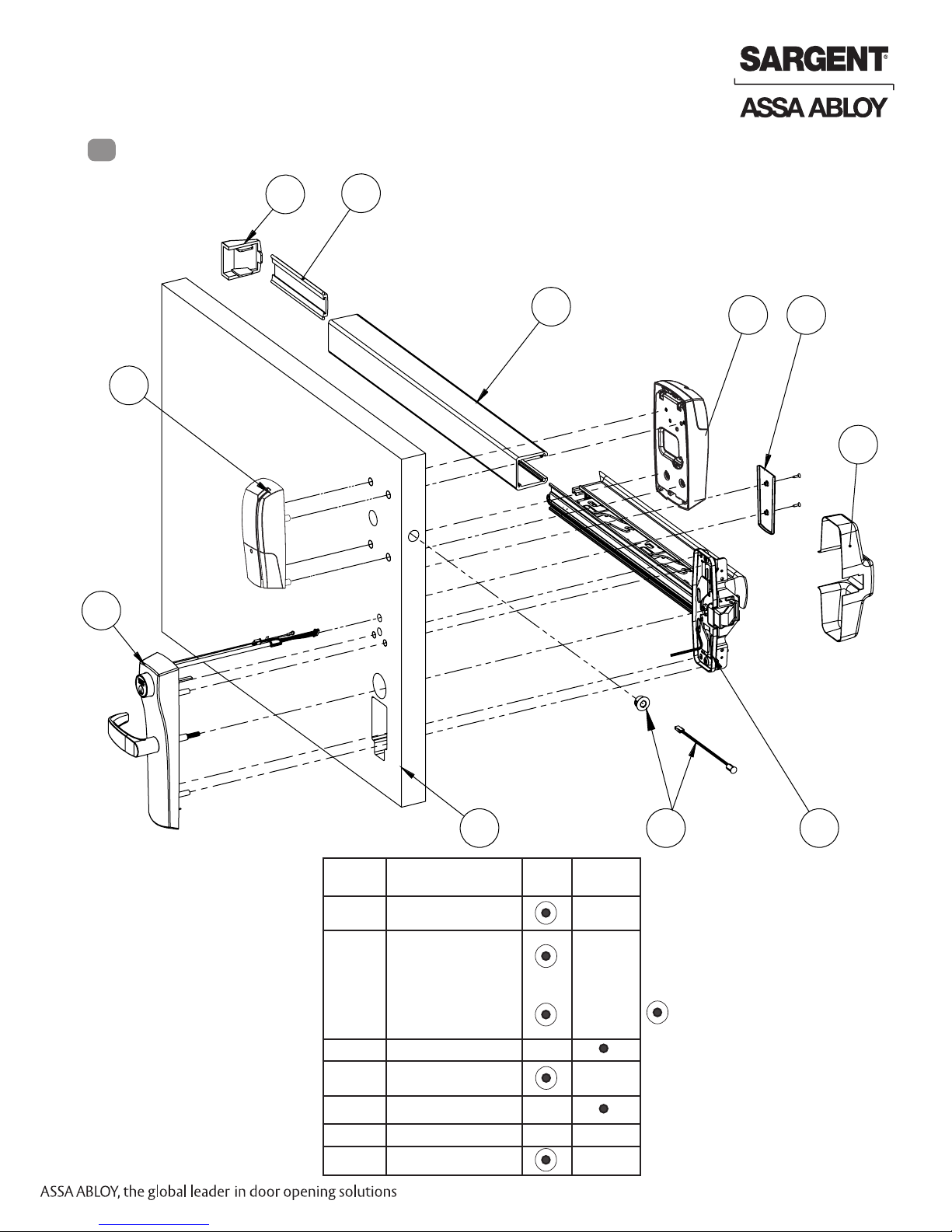
Major Component Assembly Breakdown
5
4
6
1
5
2
3
Item Description EK Kit Existing
1 Outside Escutcheon
Assembly
2 Outside Trim Assembly
Replacement EK Retrofit
Kit P/N 777-5-EK1
*Replacement for
Mechanical
(dummy) trim only
P/N 706-5-EK1
3 Door
4 Inside Escutcheon
Assembly
5 Exit Device Assembly
6 Wire Cover
7 Door Position Switch
5
Hardware
1-800-810-WIRE • www.sargentlock.com • A8112C
7
Indicates replacement part item consult factory for ordering string
5
Copyright © 2016, Sargent Manufacturing Company, an ASSA ABLOY Group company. All rights reserved.
Reproductions in whole or in part without express written permission of Sargent Manufacturing Company is prohibited.
04/30/16

EK Exit Device Retrofit Kit for Passport 1000
1 Remove All Von Duprin® 98/99 Exit Hardware from Door
See diagram and part description on page 4 showing existing assemblies to be removed.
2 Door Preparation
Inside
A. Verify Hand and Bevel of Door
• Check hand of door.
The trim is field reversible.
Ensure exit trim is oriented to appropriate
handing
• Door should be fitted and hung.
B. Door Preparation
• Based on 1-3/4” door thickness. Consult factory for other door thicknesses.
• Use existing door prep (Fig. 2B) to locate templates.
• Use A8104 (field prep template) or 4701 (door manufacturer template) for P1-prefix applications.
• Use A8105 (field prep template) or 4700 (door manufacturer template) for P2-prefix applications.
Note: All instruction examples show wood door installation.
• Refer to template for cutout requirements.
Left Hand
Reverse
LHR
Outside
Fig. 2A
Right Hand
Reverse
RHR
Outside of Door
Existing Von
Duprin 996 trim
shown
Fig. 2B
Copyright © 2016, Sargent Manufacturing Company, an ASSA ABLOY Group company. All rights reserved.
Reproductions in whole or in part without express written permission of Sargent Manufacturing Company is prohibited.
04/30/16
1-800-810-WIRE • www.sargentlock.com • A8112C
Inside of Door
Note: highlighted sections
indicate existing Von Duprin
996 trim cutouts.
6
EK Exit Device Retrofit Kit for Passport 1000
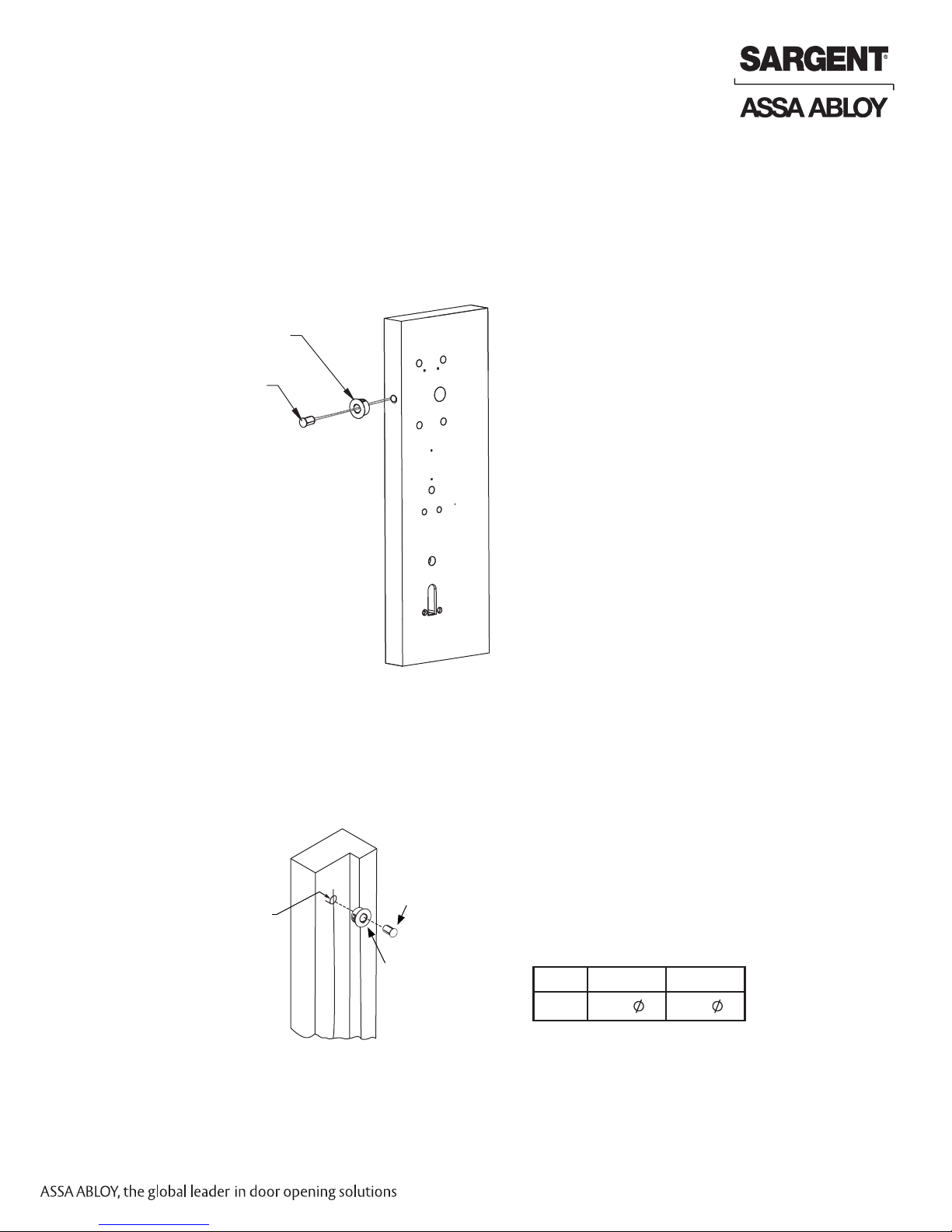
C. Install Door Position Switch (DPS)
1. Insert connector end of DPS through the raceway on the latch edge of the door (Fig. 2C).
Note: For metal doors, use DPS Collar.
2. Push DPS firmly into place by hand.
IMPORTANT: DO NOT TAP SWITCH WITH ANY TOOL.
Inside of Door
Collar is used only
with metal doors
Door Position
Switch (DPS)
Fig. 2C
3. Determine frame hole for (DPS) magnet by aligning with DPS hole on door side.
4. Cutout hole for (DPS) magnet using Table 2E to determine hole size.
5. Install (DPS) magnet into frame (Fig. 2D).
Note: For metal doors, use DPS Collar.
IMPORTANT: DO NOT TAP DPS MAGNET WITH ANY TOOL.
Door frame
Door Position
Switch Magnet
Dim 1
Table 2E
Collar is used only
with metal doors
Dim 1
Fig. 2D
Wood Frame Metal Frame
3/8” 3/4”
Copyright © 2016, Sargent Manufacturing Company, an ASSA ABLOY Group company. All rights reserved.
Reproductions in whole or in part without express written permission of Sargent Manufacturing Company is prohibited.
7
1-800-810-WIRE • www.sargentlock.com • A8112C
04/30/16
EK Exit Device Retrofit Kit for Passport 1000
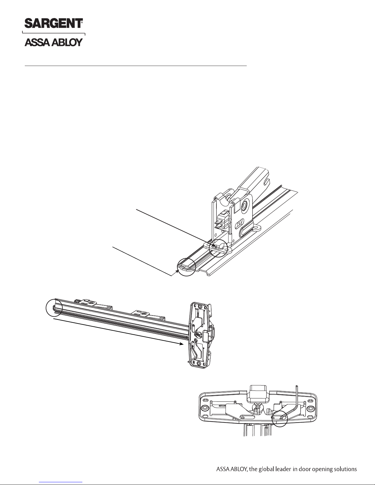
3 Von Duprin® 98/99 Series Rim Exit Hardware Preparation
A. Installing and Wiring the Request to Exit - RX Switch (not included)
The RX kit must be installed in order for the product to operate as intended. The RX kit can be ordered
from an authorized distributor. (Refer to Von Duprin® RX Switch Kit P/N 050251-00)
1. Install RX Switch assembly onto base plate assembly per manufacturer’s instructions.
• Note: Do not route wires as shown on the Von Duprin RX switch kit instructions.
• Use caution when routing wires throughout the exit device, being careful not to damage
or pinch wires.
2. Route wires through slot.
3. Route wires around edge of base
plate assembly.
4. Route wires along underside of base
plate assembly.
Fig. 3A
Riga 45
Fig. 3B
5. Route wires from switch in front along
underside of base plate, through hole
and slot.
Copyright © 2016, Sargent Manufacturing Company, an ASSA ABLOY Group company. All rights reserved.
Reproductions in whole or in part without express written permission of Sargent Manufacturing Company is prohibited.
04/30/16
1-800-810-WIRE • www.sargentlock.com • A8112C
Fig. 3C
8
 Loading...