

Page 1
™
Degree
Technical Manual
Key System
Copyright © 2013-2014, Sargent Manufacturing Company, an ASSA ABLOY Group company.
All rights reserved. Reproduction in whole or in part without the express written permission
of Sargent Manufacturing Company is prohibited.
Page 2
Table of Contents
Degree™ Key System Technical Manual
Table of Contents
The Degree™ Advantage . . . . . . . . . . . . . . . . . . . . . . . . . . . . . . . . . . . . . . . . . . 1
DG1 Key Cuts . . . . . . . . . . . . . . . . . . . . . . . . . . . . . . . . . . . . . . . . . . . . . . . . . .2
DG2 & DG3 Key Cuts . . . . . . . . . . . . . . . . . . . . . . . . . . . . . . . . . . . . . . . . . . . . .3
Pinning Formula . . . . . . . . . . . . . . . . . . . . . . . . . . . . . . . . . . . . . . . . . . . . . . . .4
Construction Master Keying (21-Option). . . . . . . . . . . . . . . . . . . . . . . . . . . . . . . .5
Visual Key Control Tamper Proof Packaging . . . . . . . . . . . . . . . . . . . . . . . . . . . . . . 6
Degree Pin Kits. . . . . . . . . . . . . . . . . . . . . . . . . . . . . . . . . . . . . . . . . . . . . . . . .7
Cylinder Parts: DG1-34 Rim/ DG1-40 Series Mortise. . . . . . . . . . . . . . . . . . . . . . . . .8
Cylinder Parts: DG2-34 Rim/ DG2-40 Series Mortise. . . . . . . . . . . . . . . . . . . . . . . . .9
Cylinder Parts: DG3-34 Rim/ DG3-40 Series Mortise. . . . . . . . . . . . . . . . . . . . . . . .10
Cylinder Parts: DG1-LFIC Cores . . . . . . . . . . . . . . . . . . . . . . . . . . . . . . . . . . . . . 11
Cylinder Parts: DG2-LFIC Cores . . . . . . . . . . . . . . . . . . . . . . . . . . . . . . . . . . . . . 12
Cylinder Parts: DG3-LFIC Cores . . . . . . . . . . . . . . . . . . . . . . . . . . . . . . . . . . . . . 13
Cylinder Parts: DG1 Bored, Auxiliary, & Integralock . . . . . . . . . . . . . . . . . . . . . . . . 14
Cylinder Parts: DG2 Bored, Auxiliary, & Integralock . . . . . . . . . . . . . . . . . . . . . . . . 15
Cylinder Parts: DG3 Bored, Auxiliary, & Integralock . . . . . . . . . . . . . . . . . . . . . . . . 16
Reproduction in whole or in part without the express written permission of Sargent Manufacturing Company is prohibited.
On The Cover
DG1-41 Mortise cylinder, Degree Key
and Degree DG1-6300 series core
1-800-727-5477 • www.sargentlock.com
90726:E 4/30/14 Copyright © 2013-2014, Sargent Manufacturing Company, an ASSA ABLOY Group company. All rights reserved.
Page 3
e Degree™ Advantage
Degree™ Key System Technical Manual
The Degree Key System
The patented Degree system from SARGENT
provides the right level of security for each
opening in your facility. Three levels of ANSI/
BHMA Grade 1 protection, from patented
keyway to UL437 certified, secures every opening.
A common key for all three levels of security
enhances key control and simplifies administrative
procedures. Key blanks are controlled through
authorized distribution and geographical
protection is available. Available for mortise, rim,
component and Large Format Interchangeable
Core (LFIC) cylinders, SARGENT offers the
right Degree of protection for every door in
your facility.
Benefits
• Patent protection from unauthorized key
duplication through 2027
• New keyway family protects system integrity
from legacy systems
• Keys are significantly stronger than
competitive systems
• User-friendly design with minimal components
provides easy field service
• Availability in all existing SARGENT cylinder
types provides cost-effective upgrade for
SARGENT facilities
• Bump resistance for added protection
Degree Level 1 (DG1) features a utility patented
keyway and provides protection against bumping
for mortise, rim and component fixed cylinders.
These cylinders easily retrofit into existing
hardware and are appropriate for most
applications. The keys for DG1 can only open
DG1 cylinders.
Degree Level 2 (DG2) builds on the utility
patented keyway of DG1 and adds patented side
bar locking with unique angled bottom pins that
provide end users with geographical exclusivity.
Cylinders provide protection against bumping
and picking. Because of its superior key control
and patent protection until 2027, DG2 products
are recommended for use in conjunction with
DG3 for new installations or when retrofitting
systems, including large format interchangeable
core systems.
Degree Level 3 (DG3) combines the utility
patented keyway and side bar locking with
unique angled bottom pins that provide end
users with geographical exclusivity, and adds
certification to UL437. They are classified as high
security because of their superior resistance to
physical attack and protection against unauthorized
key duplication. Because of its superior key control,
patent protection until 2027, and physical
strength, we recommend DG3 products for new
high-security installations or when retrofitting
systems, including large format interchangeable
core systems. SARGENT also offers anti-vandal
and high security locksets that complement
DG3 cylinders for those openings most vulnerable
to attack.
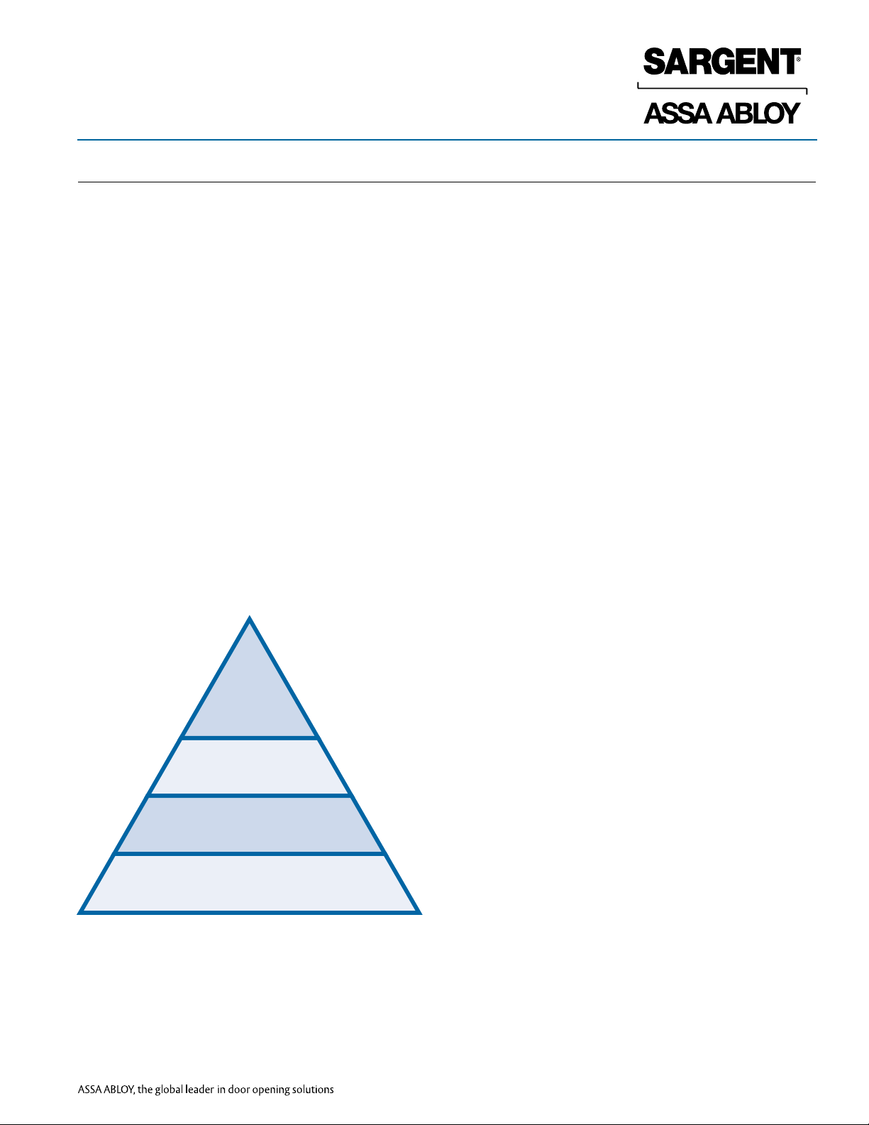
SARGENT Cylinder & Key Control Products
High
Security
Security
Patented Keyway
Open Conventional
High Security: UL437 Drill & Pick Resistant Systems offer protection
against physical attacks. Includes Degree DG3, UL-Signature
and UL-Keso.
Extra
Security: Protection against picking. Includes Degree DG2,
Control
Signature and Keso.
Patented Keyway: Keys are protected against unauthorized
duplication. Includes Degree DG1 and XC.
Open Conventional: Legacy systems whose patents
have run out and are not protected.
Intermediate
Control
Reproduction in whole or in part without the express written permission of Sargent Manufacturing Company is prohibited.
1-800-727-5477 • www.sargentlock.com
1
90726:E 4/30/14 Copyright © 2013-2014, Sargent Manufacturing Company, an ASSA ABLOY Group company. All rights reserved.
Page 4
DG1 Key Cuts
Degree™ Key System Technical Manual
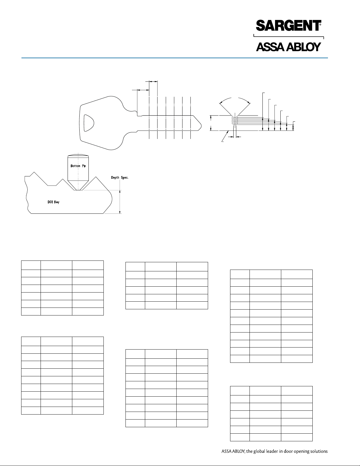
DG1 cuts from Bow to Tip
.170±.001
.2440±.0025
TYP.
1234 56
(.307)
90°
TYP.
.054±.001
REFERENCE LINE BOTTOM OF KEY
.271±.0015
.241±.0015
(1)
(2)
.211±.0015
.181±.0015
.151±.0015
(3)
(4)
.121±.002
(5)
(6)
Bottom Pins (BP)
for DG1- cylinders
Size # Part No. Length
1 DG-0021 .231
2 DG-0022 .261
3 DG-0023 .291
4 DG-0024 .321
5 DG-0025 .351
6 DG-0026 .381
Driver Pins (DP)
for DG1- standard cylinders
Size # Part No. Length
1 DG-0051 .030
2 DG-0052 .060
3 DG-0053 .090
4 DG-0054 .120
5 DG-0055 .150
6 DG-0246 .180
7 DG-0247 .210
8 DG-0248 .240
9 DG-0249 .270
Reproduction in whole or in part without the express written permission of Sargent Manufacturing Company is prohibited.
Master Wafers (MW)
for all DG- series
Size # Part No. Length
1 DG-0051 .030
2 DG-0052 .060
3 DG-0053 .090
4 DG-0054 .120
5 DG-0055 .150
Driver Pins (DP)
for DG2- & DG3- cylinders and
all DG- Large Format
Interchangeable Cores
Size # Part No. Length
1 DG-0051 .030
2 DG-0052 .060
3 DG-0053 .090
4 DG-0054 .120
5 DG-0045 .150
6 DG-0044 .180
7 DG-0043 .210
8 DG-0042 .240
9 DG-0041 .270
Control Drivers (CD) for all DG- Large
Format Interchangeable Cores (3 & 4
Chambers)
Size # Part No. Length
1 DG-0051 .030
2 DG-0052 .060
3 DG-0053 .090
4 DG-0054 .120
5 DG-0055 .150
6 n/a
7 DG-0247 .210
8 DG-0248 .240
9 DG-0249 .270
10 DG-0250 .300
11 DG-0251 .330
Driver Pins (DP) for Bump
Resistance (DG1 Only)
Size # Part No. Length
1 DG-0036 .120
2 DG-0035 .150
3 DG-0034 .180
5 DG-0033 .210
6 DG-0032 .240
7 DG-0031 .270
90726:E 4/30/14 Copyright © 2013-2014, Sargent Manufacturing Company, an ASSA ABLOY Group company. All rights reserved.
2
1-800-727-5477 • www.sargentlock.com
Page 5
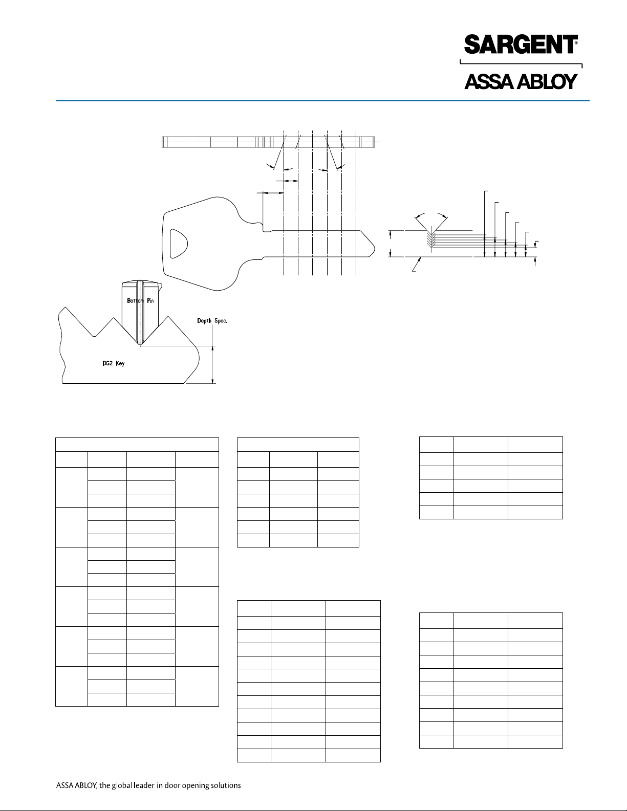
DG2 & DG3 Key Cuts
Degree™ Key System Technical Manual
DG2 DG3 cuts
Dimensions shown are to theoretical intersection
Bottom Pins (BP)
for DG2- & DG3- cylinders
.170 ±.001
.2440±.0025
R
C
R
20°
TYP.
1234 56
LL
20°
C
.259±.001 (1)
.229±.001 (2)
.199±.001 (3)
.169±.001 (4)
.139±.001 (5)
.109±.001 (6)
(.307)
86°
TYP.
REFERENCE LINE BOTTOM OF KEY
Master Wafers (MW)
for all DG- series
First 5 positions (Angled Pins)
Size # Angle Part No. Length
L DG-0111
1
R DG-0131
L DG-0112
2
R DG-0132
L DG-0113
3
R DG-0133
L DG-0114
4
R DG-0134
L DG-0115
5
R DG-0135
L DG-0116
6
R DG-0136
.231C DG-0121
.261C DG-0122
.291C DG-0123
.321C DG-0124
.351C DG-0125
.381C DG-0126
6th (last) position
Size # Part No. Length
1 DG-0021 .231
2 DG-0022 .261
3 DG-0023 .291
4 DG-0024 .321
5 DG-0025 .351
6 DG-0026 .381
Control Drivers (CD) for all DGLarge Format Interchangeable
Cores (3 & 4 Chambers)
Size # Part No. Length
1 DG-0051 .030
2 DG-0052 .060
3 DG-0053 .090
4 DG-0054 .120
5 DG-0055 .150
6 n/a
7 DG-0247 .210
8 DG-0248 .240
9 DG-0249 .270
10 DG-0250 .300
11 DG-0251 .330
Size # Part No. Length
1 DG-0051 .030
2 DG-0052 .060
3 DG-0053 .090
4 DG-0054 .120
5 DG-0055 .150
Driver Pins (DP)
for DG2- & DG3- cylinders and
all DG- Large Format
Interchangeable Cores
Size # Part No. Length
1 DG-0051 .030
2 DG-0052 .060
3 DG-0053 .090
4 DG-0054 .120
5 DG-0045 .150
6 DG-0044 .180
7 DG-0043 .210
8 DG-0042 .240
9 DG-0041 .270
Reproduction in whole or in part without the express written permission of Sargent Manufacturing Company is prohibited.
1-800-727-5477 • www.sargentlock.com
3
90726:E 4/30/14 Copyright © 2013-2014, Sargent Manufacturing Company, an ASSA ABLOY Group company. All rights reserved.
Page 6

Pinning Formula
Degree™ Key System Technical Manual
Fixed Core Cylinders - All 6 Chambers
Large Format Interchangeable Cores
(Chambers 1-2-5-6)
Non-LFIC
Driver Pin (DP)
10 MINUS
Plug Total
Master Wafer
(MW) Pin =
Deepest Minus
Shallowest
Operating Cut
Bottom Pin =
Shallowest
Operating Cut
Example
Master Key 1 2 3 4 6 4
Change Key 3 4 5 2 2 2
Driver Pin (DP) 7 6 5 6 4 6
Master Wafer (MW) 2 2 2 2 4 2
Bottom Pin (BP) 1 2 3 2 2 2
Plug Total (MW + BP)
Large Format Interchangeable Core -
(Chambers 3 and 4 Only)
LFIC
Driver Pin (DP)
13 MINUS Plug
Total and
Control Driver
Control
Driver (CD) =
Control Cut PLUS 6
MINUS Plug Total
Master Wafer
(MW) Pin =
Deepest MINUS
Shallowest
Operating Cut
Bottom Pin =
Shallowest
Operating Cut
Control Chambers
Example
Control Key 1 5 5 4 3 2
Master Key 1 5 2 6 3 2
Change Key 3 1 4 3 1 5
Driver Pin (DP) 7 5 2 3 7 5
Control Driver (CD) x x 7 4 x x
Master Wafer (MW) 2 4 2 3 2 3
Bottom Pin (BP) 1 1 2 3 1 2
Plug Total (MW +BP)
Instructions
Bottom Pin = shallowest operating cut
Master Wafer (if required) = Deepest minus
shallowest operating cut
(Plug Total = Bottom Pin + Master Wafer)
Driver Pin = 10 MINUS Plug Total
Reproduction in whole or in part without the express written permission of Sargent Manufacturing Company is prohibited.
90726:E 4/30/14 Copyright © 2013-2014, Sargent Manufacturing Company, an ASSA ABLOY Group company. All rights reserved.
4
1-800-727-5477 • www.sargentlock.com
Instructions
Bottom Pin = shallowest operating cut
Master Wafer (if required) = Deepest minus
shallowest operating cut
(Plug Total = Bottom Pin + Master Wafer)
Control Driver (CD) = Control cut PLUS 6 MINUS
Plug Total
Driver Pin = 13 MINUS Plug Total and CD# = DP
Page 7

Construction Master Keying
(21- Option)
Degree™ Key System Technical Manual
Construction Master Keying (Lost/Wafer Design) for DG1-, DG2- & DG3-
SARGENT Degree cylinders when master keyed are offered with the
convenience of construction keying when specified with the 21- option.
This is not recommended with DG3 key systems or any system where strict
key control and management is enforced.
Construction keying simplifies the process when the building gets turned
over. With this feature, the 21- cylinder is master keyed with a special
construction feature in one of the chambers. The plug is prepped in two
places along both sides of the same chamber containing the construction
feature. This allows the construction master key to be used during the
construction phases.
It is highly recommended that all construction keys are collected and
accounted for once the project is complete to protect the integrity of the
key system. This is not recommended with DG3 key systems or any system
where strict key control & management is enforced.
Wafer
New systems supplied with six construction master keys unless
otherwise specified. Orders to existing key systems that require
additional construction keys are to be specified and ordered separately.
Orders with 21- will have all change keys shipped separately from
hardware. Six construction master keys provided per system unless
otherwise specified.
The 21- is not available with hotel function cylinders or large format
interchangeable cores (6300 series). If construction keying is required
for LFIC, specify 64-DG- construction keyed cores.
As change key rotates,
construction wafer falls into
“donut” hole in the side of plug.
Only construction wafer will
fall due to hole through its center.
Cutaway cylinder showing construction
master key being used, putting the wafer
below the shear line while key is turned.
Note the two empty “donut” holes
on either side of the chamber.
Change key rotated to
position for extraction.
Change key inserted in cylinder
putting the wafer at the shear line.
Construction key inserted after
wafer is trapped. Driver now
extends into plug chamber.
Construction key if used will not rotate.
Reproduction in whole or in part without the express written permission of Sargent Manufacturing Company is prohibited.
1-800-727-5477 • www.sargentlock.com
5
90726:E 4/30/14 Copyright © 2013-2014, Sargent Manufacturing Company, an ASSA ABLOY Group company. All rights reserved.
Page 8

Visual Key Control
Tamper Proof Packaging
Degree™ Key System Technical Manual
Visual Key Control (Stamping)
To allow for easier key and cylinder identification, SARGENT offers permanent stamping of keys and/or optional cylinder concealed stamping with
industry standard alpha-numeric key set symbols.
All DG keys are stamped with key set symbol and “DO NOT DUPLICATE” as standard.
All DG master and control keys are stamped with the key set symbol and the key system register # cylinders as standard, (Item B) unless alternate
stamping is requested on the order.
Master level keys do not include bitting numbers. Master level keys include system register numbers stamped on the first line and the standard visual key
control designations on the second line (Item B).
Change keys have one line for up to 7 characters for key set stamping available for permanent Visual Key Control
• Key and cylinder identified by industry standard alpha-numeric keyset symbols
• Cylinder-slide stamping available on mortise, rim, LFIC and all bored cylinders except for 8-Line and 7600 (Items C, D, & E)
• Core side engraving available for 8-Line and 7600 (Item F)
Keyway
AB1
PAT. NO. 7,552,608
DO NOT DUPLICATE
Item A
Change (Day)
Key Stamping
Key Set
Example
system
number
Symbol to
identify
factory-cut
key
PAT. NO. 7,552,608
DO NOT DUPLICATE
Item B
Master Level
Key Stamping
Example
of keyset
Item C
Item D
Item E
Item F
Tamper Proof Packaging
Reproduction in whole or in part without the express written permission of Sargent Manufacturing Company is prohibited.
For the highest level of security for the end user, tamper proof packaging is used on all Degree master keys and key blanks. This heat sealed shrink wrap
identified with “SARGENT Sealed For Your Security” provides assurance of the integrity of the factory generated key system.
90726:E 4/30/14 Copyright © 2013-2014, Sargent Manufacturing Company, an ASSA ABLOY Group company. All rights reserved.
6
1-800-727-5477 • www.sargentlock.com
Page 9

Degree Pin Kits
Degree™ Key System Technical Manual
437 DG1 Standard Pinning Kit
The 437 DG1 Kit is used to pin DG1 fixed and LFIC cylinders. The heavy duty steel kit prevents pins from mixing.
The kit includes:
- 100 each of bottom pins sizes 1-6
- 100 each of control drivers sizes 1-11
- 100 each of driver pins sizes 1-9
- 100 each of bump resistant pins sizes 4-9
- 25 sidebar springs part number DG-0059
- 100 KIK spring cover part number 13-1341
- 25 KIL/MRT/RIM/LFIC spring cover DG-0040
- 10 each Sidebar (LFIC only) part number DG-2818
- 100 each compression spring part number DG-0017
- 100 each compression spring (LFIC only) part number DG-0097
- Tweezer
- Degree key gauge
See pages 2 and 3 for individual pin part #s.
The kit has additional empty compartments for future upgrades to DG2 and DG3 cylinders.
The 437 DGM “Master Kit” has all pins needed for pinning DG1, DG2 and DG3 cylinders.
437 DGM Master Pinning Kit
The 437 DGM “Master Kit” includes all pins needed to re-pin DG1, DG2 and DG3 cylinders.
Kit includes all the same components as in the 437 DG1 kit, with the additional parts to service DG2
and DG3 cylinders.
- 10 each Side bar part number DG 0056
- 25 each slider spring part number DG 0060
- 100 each of Left, Center and Right “Chisel Bottom Pins” sizes 1 thru 6
See pages 2 and 3 for individual part numbers.
Cylinder Spray Lubricant
Degree cylinders are mechanical devices and require preventive maintenance. At a minimum, Degree
cylinders should be lubricated twice a year; more if installed in extreme installations.
Degree cylinders should not be exposed to chemical washes or painted.
3.0 oz aerosol part number 18-0070.
Cylinder Spray Cleaner/Deicer: 3.0 oz aerosol part number 18-0435.
1-800-727-5477 • www.sargentlock.com
7
Reproduction in whole or in part without the express written permission of Sargent Manufacturing Company is prohibited.
90726:E 4/30/14 Copyright © 2013-2014, Sargent Manufacturing Company, an ASSA ABLOY Group company. All rights reserved.
Page 10

Cylinder Parts:
DG1-34 Rim/ DG1-40 Series Mortise
Degree™ Key System Technical Manual
DG1-34 Rim/ DG1-40 Series Mortise Cylinder Parts
Item Description Part Number Where Used / Cylinder Length Comment
DG-2894 DG1-34 –
DG-2911 DG1-41 & 78-DG1-41 1-1/8" (29mm)
1 Plug
2 Cylinder Shell
3 Conical Bottom Pin See Page 2 and 3 DG1-40 Series Mortise & DG1-34 Rim
4 Master Wafer See Page 2 and 3 DG1-40 Series Mortise & DG1-34 Rim
5 Bump-Resistant Driver Pin See Page 2 and 3 DG1-40 Series Mortise & DG1-34 Rim
6 Compression Spring DG-0017 DG1-40 Series Mortise & DG1-34 Rim
7 Cam See Degree Catalog DG1-40 Series Mortise
8 Screw DG-0016 DG1-40 Series Mortise # 2-56 x 5/16" (8mm) PH. FL.
10 Retainer DG-0090 DG1-34 Rim
11 Tailpiece Retainer DG-0195 DG1-34 Rim
12 Tailpiece DG-0196 DG1-34 Rim
13 Spring Cover DG-0040 DG1-40 Series Mortise & DG1-34 Rim
14 Standard Connecting Screws 13-0074 DG1-34 Rim # 12-24 x 2-1/8" (54mm)
15 Rim Cylinder Back Plate 13-0086 DG1-34 Rim
DG-2912 DG1-42 & 78-DG1-42 1-1/4" (32mm)
DG-2913 DG1-43 & 78-DG1-43 1-3/8" (35mm
DG-2914 DG1-44 1-1/2" (38mm)
DG-2915 DG1-46 1-3/4" (44mm)
DG-0621 DG1-41 & DG1-34 1-1/8" (29mm)
DG-0622 DG1-42 1-1/4" (32mm)
DG-0623 DG1-43 1-3/8" (35mm)
DG-0624 DG1-44 1-1/2" (38mm)
DG-0625 DG1-46 1-3/4" (44mm)
DG-0221 78-DG1-41 1-1/8" (29mm)
DG-0222 78-DG1-42 1-1/4" (32mm)
DG-0223 78-DG1-43 1-3/8" (35mm)
Plug finishes: 04, 15
Shell finishes: 03, 04, 09,
10, 10B, 10BL, 14, 15,
20D, 26, 26D
No finish.
For use with mortise locks
with LE3 or LE4 trim only.
13
6
5
3
2
Reproduction in whole or in part without the express written permission of Sargent Manufacturing Company is prohibited.
90726:E 4/30/14 Copyright © 2013-2014, Sargent Manufacturing Company, an ASSA ABLOY Group company. All rights reserved.
8
1-800-727-5477 • www.sargentlock.com
4
15
8
7
12
11
1
10
14
Page 11

Cylinder Parts:
DG2-34 Rim/ DG2-40 Series Mortise
Degree™ Key System Technical Manual
DG2-34 Rim / DG2-40 Series Mortise Cylinder Parts
Item Description Part Number Where Used / Cylinder Length Comment
DG-0191 DG2-34 –
DG-0411 DG2-41 & 78-DG2-41 1-1/8" (29mm)
1 Plug
2 Cylinder Shell
3 Chisel Tipped Bottom Pin See Page 2 and 3 DG2-40 Series Mortise & DG2-34 Rim In pin chambers 1 through 5
4 Conical Bottom Pin See Page 2 and 3 DG2-40 Series Mortise & DG2-34 Rim In pin chamber 6 only
5 Master Wafer See Page 2 and 3 DG2-40 Series Mortise & DG2-34 Rim
6 Driver Pin See Page 2 and 3 DG2-40 Series Mortise & DG2-34 Rim
7 Compression Spring DG-0017 DG2-40 Series Mortise & DG2-34 Rim
8 Slider C6M6 DG-0087 DG2-40 Series Mortise & DG2-34 Rim For keys with a #6 slider cut
9 Slider Spring DG-0060 DG2-40 Series Mortise & DG2-34 Rim
10 Sidebar Spring DG-0059 DG2-40 Series Mortise & DG2-34 Rim
11 Sidebar DG -2818 DG2-40 Series Mortise & DG2-34 Rim
12 Cam See Degree Catalog DG2-40 Series Mortise
13 Screw DG-0016 DG2-40 Series Mortise # 2-56 x 5/16" (8mm) PH. FL.
15 Retainer DG-0090 DG2-34 Rim
16 Tailpiece Retainer DG-0195 DG2-34 Rim
17 Tailpiece DG-0196 DG2-34 Rim
18 Spring Cover DG-0040 DG2-40 Series Mortise & DG2-34 Rim
19 Standard Connecting Screws 13-0074 DG2-34 Rim # 12-24 x 2-1/8" (54mm)
20 Rim Cylinder Back Plate 13-0086 DG2-34 Rim
DG-0412 DG2-42 & 78-DG2-42 1-1/4' (32mm)
DG-0413 DG2-43 & 78-DG2-43 1-3/8" (35mm
DG-0414 DG2-44 1-1/2" (38mm)
DG-0415 DG2-46 1-3/4" (44mm)
DG-0631 DG2-41 & DG2-34 1-1/8" (29mm)
DG-0632 DG2-42 1-1/4" (32mm)
DG-0633 DG2-43 1-3/8" (35mm)
DG-0634 DG2-44 1-1/2" (38mm)
DG-0635 DG2-46 1-3/4" (44mm)
DG-0231 78-DG2-41 1-1/8" (29mm)
DG-0232 78-DG2-42 1-1/4" (32mm)
DG-0233 78-DG2-43 1-3/8" (35mm)
Plug finishes: 04, 15
Shell finishes: 03, 04, 09,
10, 10B, 10BL, 14, 15,
20D, 26, 26D
No finish.
For use with mortise locks
with LE3 or LE4 trim only.
18
7
6
3
2
11
10
8
9
5
4
16
1
13
12
17
15
20
1-800-727-5477 • www.sargentlock.com
19
Reproduction in whole or in part without the express written permission of Sargent Manufacturing Company is prohibited.
9
90726:E 4/30/14 Copyright © 2013-2014, Sargent Manufacturing Company, an ASSA ABLOY Group company. All rights reserved.
Page 12

Cylinder Parts:
DG3-34 Rim/ DG3-40 Series Mortise
Degree™ Key System Technical Manual
DG3-34 Rim / DG3-40 Series Mortise Cylinder Parts
Item Description Part Number Where Used / Cylinder Length Comment
DG-2895 DG3-34 –
DG-2881 DG3-41 & 78-DG3-41 1-1/8" (29mm)
DG-2882 DG3-42 & 78-DG3-42 1-1" (32mm)
DG-2883 DG3-43 & 78-DG3-43 1-3/8" (35mm
DG-2884 DG3-44 1-1/2" (38mm)
DG-2885 DG3-46 1-3/4" (44mm)
DG-0641 DG3-41 & DG3-34 1-1/8" (29mm)
DG-0642 DG3-42 1-1/4" (32mm)
DG-0643 DG3-43 1-3/8" (35mm)
DG-0644 DG3-44 1-1/2" (38mm)
DG-0645 DG3-46 1-3/4" (44mm)
DG-0241 78-DG3-41 1-1/8" (29mm)
DG-0242 78-DG3-42 1-1/4" (32mm)
DG-0243 78-DG3-43 1-3/8" (35mm)
Plug finishes: 04, 15
Shell finishes: 03, 04, 09,
10, 10B, 10BL, 14, 15,
20D, 26, 26D
No finish.
For use with mortise locks
with LE3 or LE4 trim only.
10
11
12
13
14
16
17
18
19
20
21
1
2
3
Chisel Tipped Bottom Pin See Page 2 and 3 DG3-40 Series Mortise & DG3-34 Rim In pin chambers 1 through 5
4
5
6
7
8
9
Standard Connecting Screws 13-0074 DG3-34 Rim # 12-24 x 2-1/8" (54mm)
Plug
Cylinder Shell
Conical Bottom Pin See Page 2 and 3 DG3-40 Series Mortise & DG3-34 Rim In pin chamber 6 only
Master Wafer See Page 2 and 3 DG3-40 Series Mortise & DG3-34 Rim
Driver Pin See Page 2 and 3 DG3-40 Series Mortise & DG3-34 Rim
Compression Spring DG-0017 DG3-40 Series Mortise & DG3-34 Rim
Slider C6M6 DG-0087 DG3-40 Series Mortise & DG3-34 Rim For keys with a #6 slider cut
Slider Spring DG-0060 DG3-40 Series Mortise & DG3-34 Rim
Sidebar Spring DG-0059 DG3-40 Series Mortise & DG3-34 Rim
Sidebar DG -2818 DG3-40 Series Mortise & DG3-34 Rim
Security Plate DG-0057 DG3-40 Series Mortise & DG3-34 Rim Required for UL437
Cam See Degree Catalog DG3-40 Series Mortise
Screw DG-0016 DG3-40 Series Mortise # 2-56 x 5/16" (8mm) PH. FL.
Retainer DG-0090 DG3-34 Rim
Tailpiece Retainer DG-0195 DG3-34 Rim
Tailpiece DG-0196 DG3-34 Rim
Spring Cover DG-0040 DG3-40 Series Mortise & DG3-34 Rim
Cylinder Back Plate 13-0086 DG3-34 Rim
19
7
6
3
2
12
Reproduction in whole or in part without the express written permission of Sargent Manufacturing Company is prohibited.
8
90726:E 4/30/14 Copyright © 2013-2014, Sargent Manufacturing Company, an ASSA ABLOY Group company. All rights reserved.
10
1-800-727-5477 • www.sargentlock.com
9
11
10
5
4
17
1
14
13
18
16
21
20
Page 13

Cylinder Parts:
DG1-LFIC Cores
Degree™ Key System Technical Manual
DG1 LFIC Cores
Item Description Part Number Comment
1
2
3
4
5
6
7
8
9
10
11
12
Plug DG-0200 Plug finishes: 04, 15
Cylinder Shell DG-0290 Shell finishes: 04, 15
Control Sleeve DG-0215
Conical Bottom Pin See Page 2 and 3
Master Wafer See Page 2 and 3
Control Pin See Page 2 and 3
Driver Pin See Page 2 and 3
Compression Spring DG-0097
Plug Retainer DG-0090
Sidebar Spring DG-0059
Sidebar DG-0056
Spring Cover DG-0040
12
8
7
5
6
9
4
2
1
3
10
11
1-800-727-5477 • www.sargentlock.com
11
Reproduction in whole or in part without the express written permission of Sargent Manufacturing Company is prohibited.
90726:E 4/30/14 Copyright © 2013-2014, Sargent Manufacturing Company, an ASSA ABLOY Group company. All rights reserved.
Page 14

Cylinder Parts:
DG2-LFIC Cores
Degree™ Key System Technical Manual
DG2 LFIC Cores
Item Description Part Number Comment
1 Plug DG-0201 Plug finishes: 04, 15
2 Cylinder Shell DG-0291 Shell finishes: 04, 15
3 Control Sleeve DG-0216
4 Chisel Tipped Bottom Pin See Page 2 and 3 In pin chambers 1 through 5
5 Conical Bottom Pin See Page 2 and 3 In pin chamber 6 only
6 Master Wafer See Page 2 and 3
7 Control Pin See Page 2 and 3
8 Driver Pin See Page 2 and 3
9 Compression Spring DG-0097
10 Slider C6M6 DG-0087 For keys with a #6 slider cut
11 Slider Spring DG-0060
12 Sidebar Spring DG-0059
13 Sidebar DG-2818
14 Plug Retainer DG-0090
15 Spring Cover DG-0040
15
9
7
4
2
1
12
Reproduction in whole or in part without the express written permission of Sargent Manufacturing Company is prohibited.
11
10
13
8
6
5
14
3
90726:E 4/30/14 Copyright © 2013-2014, Sargent Manufacturing Company, an ASSA ABLOY Group company. All rights reserved.
12
1-800-727-5477 • www.sargentlock.com
Page 15

Cylinder Parts:
DG3-LFIC Cores
Degree™ Key System Technical Manual
DG3 LFIC Cores
Item Description Part Number Comment
1 Plug DG-2901 Plug finishes: 04, 15
2 Cylinder Shell DG-0292 Shell finishes: 04, 15
3 Control Sleeve DG-0216
4 Chisel Tipped Bottom Pin See Page 2 and 3 In pin chambers 1 through 5
5 Conical Bottom Pin See Page 2 and 3 In pin chamber 6 only
6 Master Wafer See Page 2 and 3
7 Control Pin See Page 2 and 3
8 Driver Pin See Page 2 and 3
9 Compression Spring DG-0097
10 Slider C6M6 DG-0087 For keys with a #6 slider cut
11 Slider Spring DG-0060
12 Sidebar Spring DG-0059
13 Sidebar DG-2818
14 Plug Retainer DG-0090
15 Spring Cover DG-0040
15
9
7
4
2
1
12
13
11
10
8
6
5
14
3
Reproduction in whole or in part without the express written permission of Sargent Manufacturing Company is prohibited.
1-800-727-5477 • www.sargentlock.com
13
90726:E 4/30/14 Copyright © 2013-2014, Sargent Manufacturing Company, an ASSA ABLOY Group company. All rights reserved.
Page 16

Cylinder Parts:
DG1 Bored, Auxiliary & Integralock
Degree™ Key System Technical Manual
13
6
5
3
2
1
4
9
8
7
12
11
10
DG1 Bored, Auxiliary, & Integralock Cylinder Parts
Item Description Part Number Where Used / Cylinder Length Comment
Plug with tailpiece retainer
1
2
3
4
5
6
7
8
9
10
11
12
Reproduction in whole or in part without the express written permission of Sargent Manufacturing Company is prohibited.
13
(item 7)
Plug with roll pin DG-3071 7, 8, 9 Line Cylinders (Knob Locks)
Plug DG-3029 460, 470, 480, 7500DB Series Deadbolt Cylinders
Plug DG-3043 7600 Integralock Cylinder
Cylinder Shell
Conical Bottom Pin See Page 2 and 3 All Cylinders
Master Wafer See Page 2 and 3 All Cylinders
Driver Pin See Page 2 and 3 All Cylinders
Compression Spring DG-0017 All Cylinders
Tailpiece Retainer 13-0680 6, 7, 8L, 10, 11, 6500, 7500 Line Cylinders (Lever Locks)
Tailpiece
Plug Retainer DG-0090
Plug Retainer (Deadbolt) DG-0150 460, 470, 480, 7500DB Series Deadbolt Cylinders
Retainer Screw DG-0151 460, 470, 480, 7500DB Series Deadbolt Cylinders # 2-56 x 1/4" (6mm) PH. PAN
Tailpiece
Spring Cover
DG-3061
DG-0171 6, 7, 8L, 10, 11, 6500, 7500 Line Cylinders (Lever Locks)
DG-0261 7, 8, 9 Line Cylinders (Knob Locks)
DG-0161 460, 470, 480, 7500DB Series Deadbolt Cylinders
DG-0271 7600 Integralock Cylinder
13-0895 7, 8L, 10, 6500, 7500 Line Cylinders (Lever Locks)
13-1385 11 Line Cylinders
13-0907 6 Line (S & N knobs) Cylinders
13-0908 6 Line (B knob) Cylinders
DG-2875 Single-Cylinder Deadbolts
DG-2876 Double-Cylinder Deadbolts
13-1341
DG-0039
6, 7, 8L, 10, 11, 6500, 7500 Line Cylinders
(Lever Locks)
Plug finishes: 04, 15
No finish
6, 7, 8L, 10, 11, 6500, 7500 Line Cylinders (Lever Locks)
7, 8, 9 Line Cylinders (Knob Locks)
7600 Integralock Cylinder
6, 7, 8L, 10, 11, 6500, 7500 Line Cylinders (Lever Locks)
460, 470, 480, 7500DB Series Deadbolt Cylinders
7, 8, 9 Line Cylinders (Knob Locks)
7600 Integralock Cylinder
90726:E 4/30/14 Copyright © 2013-2014, Sargent Manufacturing Company, an ASSA ABLOY Group company. All rights reserved.
14
1-800-727-5477 • www.sargentlock.com
Page 17

Cylinder Parts:
DG2 Bored, Auxiliary & Integralock
Degree™ Key System Technical Manual
18
7
5
3
2
9
815
1
6
4
14
13
12
10
11
17
16
DG2 Bored, Auxiliary, & Integralock Cylinder Parts
Item Description Part Number Where Used / Cylinder Length Comment
Plug with tailpiece retainer
1
Plug with roll pin DG-3072 7, 8, 9 Line Cylinders (Knob Locks)
2
Chisel Tipped Bottom Pin See Page 2 and 3 All Cylinders In pin chambers 1 through 5
3
4
Conical Bottom Pin See Page 2 and 3 All Cylinders In pin chamber 6 only
5
6
7
Compression Spring DG-0017 All Cylinders
8
9
10
11
12
Tailpiece Retainer 13-0680 6, 7, 8L, 10, 11, 6500, 7500 Line Cylinders (Lever Locks)
13
14
15
Plug Retainer (Deadbolt) DG-0150 460, 470, 480, 7500DB Series Deadbolt Cylinders
16
17
18
(item 12)
Plug DG-0166 460, 470, 480, 7500DB Series Deadbolt Cylinders
Plug DG-0276 7600 Integralock Cylinder
Cylinder Shell
Master Wafer See Page 2 and 3 All Cylinders
Driver Pin See Page 2 and 3 All Cylinders
Slider C6M6 DG-0087 All Cylinders For keys with a #6 slider cut
Slider Spring DG-0060 All Cylinders
Sidebar Spring DG-0059 All Cylinders
Sidebar DG -2818 All Cylinders
Tailpiece
Plug Retainer DG-0090
Retainer Screw DG-0151 460, 470, 480, 7500DB Series Deadbolt Cylinders # 2-56 x 1/4" (6mm) PH. PAN
Tailpiece
Spring Cover
DG-3062
DG-0172 6, 7, 8L, 10, 11, 6500, 7500 Line Cylinders (Lever Locks)
DG-0262 7, 8, 9 Line Cylinders (Knob Locks)
DG-0162 460, 470, 480, 7500DB Series Deadbolt Cylinders
DG-0272 7600 Integralock Cylinder
13-0895 7, 8L, 10, 6500, 7500 Line Cylinders (Lever Locks)
13-1385 11 Line Cylinders
13-0907 6 Line (S & N knobs) Cylinders
13-0908 6 Line (B knob) Cylinders
DG-2875 Single-Cylinder Deadbolts
DG-2876 Double-Cylinder Deadbolts
13-1341
DG-0039
6, 7, 8L, 10, 11, 6500, 7500 Line Cylinders
(Lever Locks)
Plug finishes: 04, 15
No finish
6, 7, 8L, 10, 11, 6500, 7500 Line Cylinders (Lever Locks)
7, 8, 9 Line Cylinders (Knob Locks)
7600 Integralock Cylinder
6, 7, 8L, 10, 11, 6500, 7500 Line Cylinders (Lever Locks)
460, 470, 480, 7500DB Series Deadbolt Cylinders
7, 8, 9 Line Cylinders (Knob Locks)
7600 Integralock Cylinder
Reproduction in whole or in part without the express written permission of Sargent Manufacturing Company is prohibited.
1-800-727-5477 • www.sargentlock.com
15
90726:E 4/30/14 Copyright © 2013-2014, Sargent Manufacturing Company, an ASSA ABLOY Group company. All rights reserved.
Page 18

Cylinder Parts:
DG3 Bored, Auxiliary & Integralock
Degree™ Key System Technical Manual
18
7
5
3
2
9
815
1
6
4
14
13
12
10
11
17
16
DG3 Bored, Auxiliary, & Integralock Cylinder Parts
Item Description Part Number Where Used / Cylinder Length Comment
Plug with tailpiece retainer
(item 12)
1
2
3
4
5
6
7
8
9
10
11
12
13
14
15
16
17
18
Reproduction in whole or in part without the express written permission of Sargent Manufacturing Company is prohibited.
Plug with roll pin DG-3073 7, 8, 9 Line Cylinders (Knob Locks)
Plug DG-3030 460, 470, 480, 7500DB Series Deadbolt Cylinders
Plug DG-3044 7600 Integralock Cylinder
Cylinder Shell
Chisel Tipped Bottom Pin See Page 2 and 3 All Cylinders In pin chambers 1 through 5
Conical Bottom Pin See Page 2 and 3 All Cylinders In pin chamber 6 only
Master Wafer See Page 2 and 3 All Cylinders
Driver Pin See Page 2 and 3 All Cylinders
Compression Spring DG-0017 All Cylinders
Slider C6M6 DG-0087 All Cylinders For keys with a #6 slider cut
Slider Spring DG-0060 All Cylinders
Sidebar Spring DG-0059 All Cylinders
Sidebar DG -2818 All Cylinders
Tailpiece Retainer 13-0680 6, 7, 8L, 10, 11, 6500, 7500 Line Cylinders (Lever Locks)
Tailpiece
Plug Retainer DG-0090
Plug Retainer (Deadbolt) DG-0150 460, 470, 480, 7500DB Series Deadbolt Cylinders
Retainer Screw DG-0151 460, 470, 480, 7500DB Series Deadbolt Cylinders # 2-56 x 1/4" (6mm) PH. PAN
Tailpiece
Spring Cover
DG-3063
DG-0172 6, 7, 8L, 10, 11, 6500, 7500 Line Cylinders (Lever Locks)
DG-0262 7, 8, 9 Line Cylinders (Knob Locks)
DG-0162 460, 470, 480, 7500DB Series Deadbolt Cylinders
DG-0272 7600 Integralock Cylinder
13-0895 7, 8L, 10, 6500, 7500 Line Cylinders (Lever Locks)
13-1385 11 Line Cylinders
13-0907 6 Line (S & N knobs) Cylinders
13-0908 6 Line (B knob) Cylinders
DG-2875 Single-Cylinder Deadbolts
DG-2876 Double-Cylinder Deadbolts
13-1341
DG-0039
6, 7, 8L, 10, 11, 6500, 7500 Line Cylinders
(Lever Locks)
Plug finishes: 04, 15
No finish
6, 7, 8L, 10, 11, 6500, 7500 Line Cylinders (Lever Locks)
7, 8, 9 Line Cylinders (Knob Locks)
7600 Integralock Cylinder
6, 7, 8L, 10, 11, 6500, 7500 Line Cylinders (Lever Locks)
460, 470, 480, 7500DB Series Deadbolt Cylinders
7, 8, 9 Line Cylinders (Knob Locks)
7600 Integralock Cylinder
90726:E 4/30/14 Copyright © 2013-2014, Sargent Manufacturing Company, an ASSA ABLOY Group company. All rights reserved.
16
1-800-727-5477 • www.sargentlock.com
Page 19

Page 20

SARGENT Manufacturing Company
100 Sargent Drive
New Haven, CT 06511 USA
800-727-5477
www.sargentlock.com
Founded in the early 1800s, SARGENT® is a market leader in locksets, cylinders, door closers, exit devices, electro-mechanical products and access control systems for
new construction, renovation, and replacement applications. The company’s customer base includes commercial construction, institutional, and industrial markets.
Copyright © 2013-2014, Sargent Manufacturing Company, an ASSA ABLOY Group company. All rights reserved. Reproduction in whole or in part without the express
written permission of Sargent Manufacturing Company is prohibited.
90726:E 4/30/14
 Loading...