

Page 1
FOR ASSISTANCE, CONTACT SARGENT AT 800-727-5477 or www.sargentlock.com
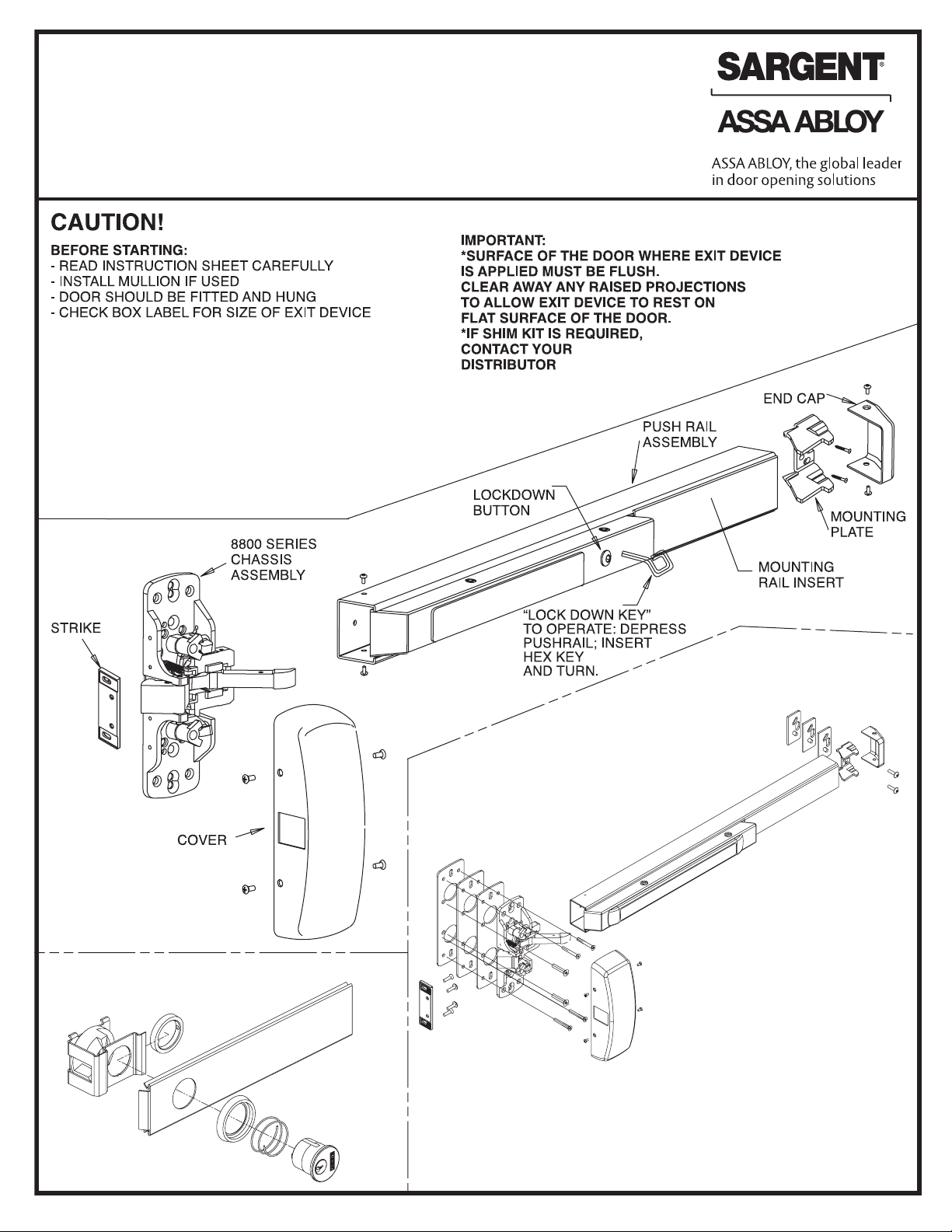
INSTRUCTIONS FOR INSTALLING 8888, 12-8888, 8800, 12-8800,
WS8800, 12-WS8800, HC-8800 and 12-HC8800 SERIES
RIM EXIT DEVICES WITH ALL STANDARD TRIM
US PATENT No 268003 • CANADIAN PATENT No RD1981
WS8800 & 12-WS8800 Rim Exit Device
(Shown Below)
- Requires 3 shims under the
chassis and end bracket
HC8800 & 12-HC8800 Rim Exit Device
(Not Shown )
- Requires 2 shims under the chassis and end bracket
16- Cylinder Lockdown
(Exploded View for clarity)
AVAILABLE STOCK LENGTHS
Length “E”: 32” door, no cut off required.
Can be cut to fit doors down to 24” wide.
Length “F”: 36” door, no cut off required.
Can be cut to fit doors down to 33” wide.
Length “J”: 42” door, no cut off required.
Can be cut to fit doors down to 37” wide.
Length “G”: 48” door, no cut off required.
Can be cut to fit doors down to 43” wide.
Copyright © 2006, 2008, 2009, 2012 Sargent Manufacturing Company, an ASSA ABLOY
Group company. All rights reserved. Reproduction in whole or in part without the
express written permission of Sargent Manufacturing Company is prohibited.
A6770P
Page 2
A6770P
Copyright © 2006, 2008, 2009, 2012 Sargent Manufacturing
Company, an ASSA ABLOY Group company. All rights reserved.
Reproduction in whole or in part without the express written
permission of Sargent Manufacturing Company is prohibited.
Page 3

IDENTIFY TYPE OF INSTALLATION
TO DETERMINE LOCATION OF
VERTICAL REFERENCE LINE
PANIC EXIT DEVICE AND
FIRE EXIT DEVICE (12- PREFIX)
649
DOUBLE DOOR WITH 980 MULLION
AND 649 STRIKES
PREPARE DOOR
PLASTIC TEMPLATE
(RECOMMENDED METHOD):
INSTALL STRIKE FIRST, THEN
EXIT DEVICE
1. APPLY PLASTIC TEMPLATE ON DOOR USING
REFERENCE LINES AND 649 STRIKE
2. MARK THEN SPOT AND DRILL HOLES
PAPER TEMPLATE:
INSTALL EXIT DEVICE FIRST, THEN STRIKE
1. APPLY PROPER TEMPLATE ON DOOR USING
REFERENCE LINES. ATTACH IT WITH SUPPLIED TAPE
2. SPOT AND DRILL HOLES
A6770P
Copyright © 2006, 2008, 2009, 2012 Sargent Manufacturing
Company, an ASSA ABLOY Group company. All rights reserved.
Reproduction in whole or in part without the express written
permission of Sargent Manufacturing Company is prohibited.
Page 4

A6770P
Copyright © 2006, 2008, 2009, 2012 Sargent Manufacturing
Company, an ASSA ABLOY Group company. All rights reserved.
Reproduction in whole or in part without the express written
permission of Sargent Manufacturing Company is prohibited.
Page 5

(PREP DOOR FOR TRIM TO BE USED)
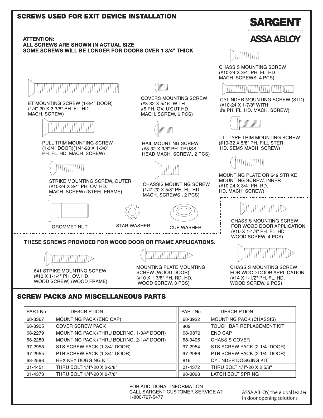
1. ATTACH CHASSIS TO THE SURFACE OF DOOR WITH
(4) #10-24 x 3/4" SCREWS
2. POSITION TRIM ON DOOR AND THROUGH-BOLT TRIM TO
CHASSIS WITH (2) 1/4-20 x 5/8" LONG SCREWS
3. USING THE CUP WASHER, THROUGH-BOLT BOTTOM OF TRIM
A6770P
THROUGH-BOLTING
Copyright © 2006, 2008, 2009, 2012 Sargent Manufacturing
Company, an ASSA ABLOY Group company. All rights reserved.
Reproduction in whole or in part without the express written
permission of Sargent Manufacturing Company is prohibited.
Page 6

(-53) LATCH BOLT MONITERING
ADJUSTMENT
NOTE: THE LATCH BOLT SWITCH WILL COME
PRE-SET FOR THE MOST COMMON APPLICATIONS.
IF THE SENSITIVITY NEEDS TO BE ADJUSTED,
FOLLOW THE STEPS BELOW.
1. LOOSEN SCREW AND NUT
2. ROTATE SWITCH (UP FOR QUICKER
REACTION OR DOWN FOR
SLOWER REACTION).
3. TIGHTEN SCREW AND NUT
4. CHECK OPERATION
NOTE: MAKE SURE SWITCH IS
LOCATED ON THE MOUNTING
POST AND THE SCREW AND
NUT ARE SECURELY FASTENED
Using your mobile phone, scan this Microsoft® Tag.
Download the free mobile app at http://gettag.mobi
Copyright © 2006, 2008, 2009, 2012 Sargent Manufacturing
Company, an ASSA ABLOY Group company. All rights reserved.
Reproduction in whole or in part without the express written
A6770P
permission of Sargent Manufacturing Company is prohibited.
SIXTH
 Loading...