

Page 1
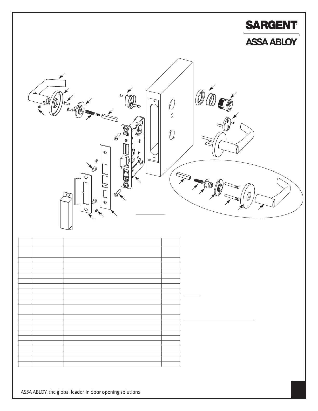
Instructions for Installing
SARGENT 7900 Lever or Knob Mortise Lock
U.S. Patent Number: 5,678,870
All trim components shown will vary by function number
Trim one-side functions - refer to separate instruction sheet
1
4
5
6
18
9
1
20
7
2
3
16
12
13
* IMPORTANT: Knob trim has
14
15
17
Part # Description Req.
1 ———– Inside lever/knob
(designs vary- some handed) 1
2 82-1038 Lever set screw 10-32 (T20 Torx head) 1
3 82-0347 Lever spring 2
4 ———– Rose (designs vary) Escutcheons optional 2
5 01-1495 Machine screw #8-32 x 5/8" 2
*6 82-4577 Inside adapter & plate assembly 1
7 82-0368 Spindle 2
8 81-0723 Through-bolt posts 2
*9 82-0691 Bushing 1
*10 82-4576 Outside mounting plate assy. 1
11 ———– Outside lever/knob
(designs vary- some handed) 1
12 ———– Lockbody (functions vary) 1
13 01-1019 Metal/machine screw #12-24 x1/2" 2
14 ———– Outside front plate (functions vary) 1
15 01-1028 Metal/machine screw #8 - 32 x 1/4" 2
16 01-1019 Machine screw # 12 - 24 x 1/2" 2
17 82-0110 Curve lip strike (1-1/4" lip) 1
18 130W Thumb Turn 1
19 97 Rosette Cylinder Collar/Rosette 1
20 ———– Cylinder-per function only (key systems vary) 21 184W
Emergency release 65 & 66 Functions
different mounting plates and
bushings than the lever trim.
21
7
3
9
10
8
4
11
Outside Lever
& Rose Assembly
(“O” Rose with “BL” Lever)
Tools Required:
• Phillips screwdriver (# 2 and # 3 size)
• Flat blade screwdriver
• T20 Torx wrench
Strikes - Standard strike part# 82-0110- 1-1/4"
lip x Lip Length x Finish (wrought box strike optional)
Screw Pack for all lockbodies - Lockbody,
front & strike screws (part #77-4236).
1
Copyright © 2006-2010, Sargent Manufacturing Company,
an ASSA ABLOY Group company. All rights reserved.
Reproduction in whole or in part without the express
written permission of Sargent Manufacturing Company
is prohibited.
A7859:C 7-16-10
1
Page 2
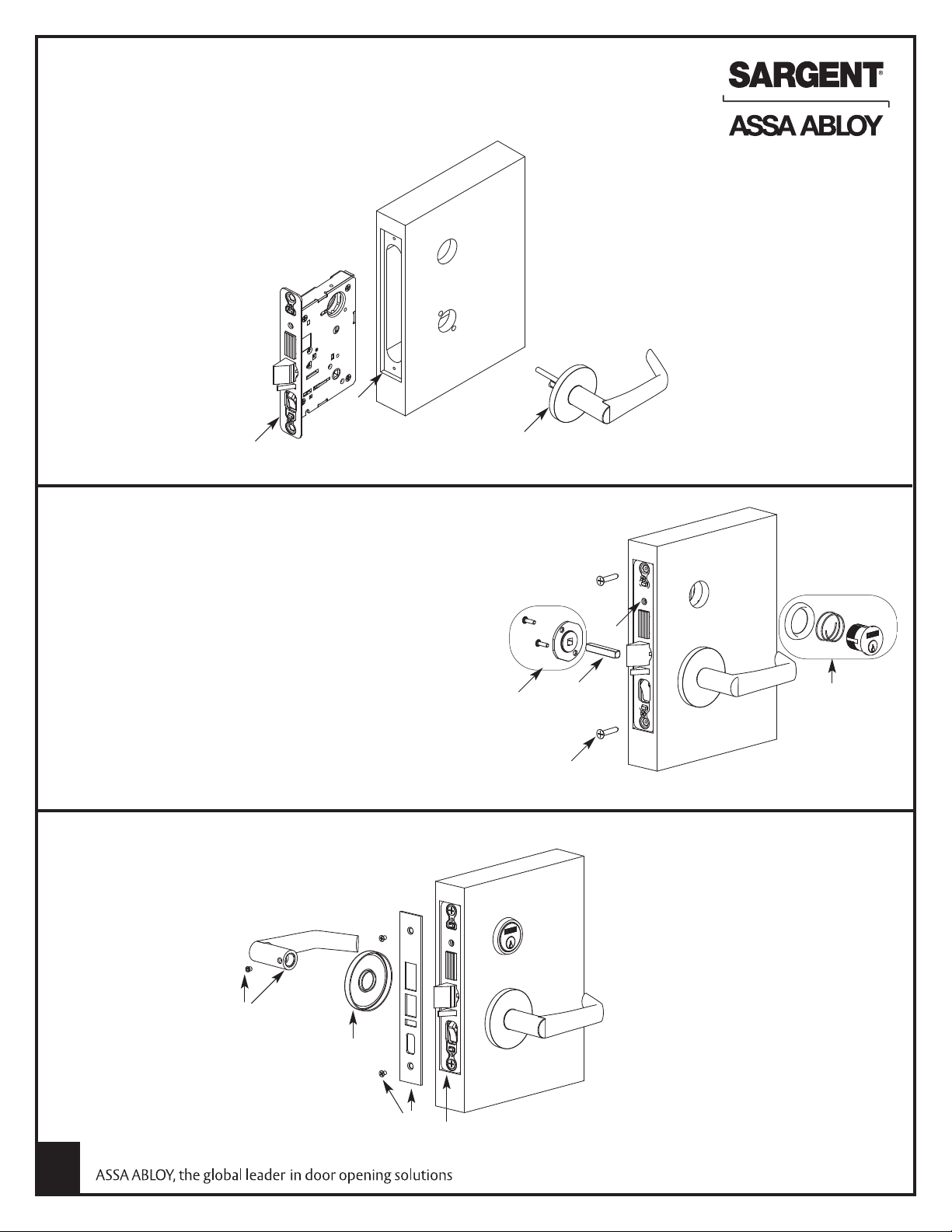
Installation Instructions for 7900 Mortise Locks
See particular trim section for your lock - rose trim shown
nside of
I
door
(1) Important: Check template 4589 or 4588 to
prep door for function holes, size & location.
Verify strike location according to
template. Clean out door pocket and
door edge of any debris.
Note: Always keep door held
open while installing lock
2) Make sure the hand of the lockbody match
(
the hand of the door (see page 4 on how to
rehand lockbody). Slide lockbody into the
door's mortise pocket.
(3) Slide outside trim assembly through the door
and lockbody.
1
2
Right Hand Door Shown
(4) For cylinder functions; slide cylinder through the spring and
collar/rosette; then thread the cylinder into the lockbody until
cylinder face is flush with collar/rosette.
Note: SARGENT logo must be horizontal & on the top portion
of the cylinder. Standard cylinder for 1-3/4" door is a #41
(1-1/8) length.
(5) Tighten cylinder clamp screw with a #2 Phillips screwdriver
(6) Secure lockbody in mortise pocket with two #12 x 1-1/4"
for wood doors or two machine screws #12-24 x 1/2" for
metal doors.
(7) Slide spindle into lockbody hub
(8) Slide inside adapter & plate assembly over spindle & secure
with two # 8 -32 x 5/8" screws
(9) Screw rose onto inside adapter &
plate assembly until tight against
door (For escutcheons, see
instruction page 3)
Outside of
door
3
8
Inside of
door
7
6
Note: If installing lever/knob
on just one side, see separate
instruction sheet
5
4
Outside of
door
(11) As required; install
thumbturn/emergency release
according to instructions on bag
(12) Attach outside front with two
#8-32 x 1/4" flat head screws
(13) Check lock for proper operation by
function number prior to closing door
10
(10) Position inside lever and secure
set screw with T20 Torx wrench
2
Note: LFIC and SFIC cylinders require a
control key (key stamped with “C”) to
remove and install the cylinder cores.
9
12
13
Copyright © 2006-2010, Sargent Manufacturing Company,
an ASSA ABLOY Group company. All rights reserved.
Reproduction in whole or in part without the express
written permission of Sargent Manufacturing Company
is prohibited.
Not provided standard; must be requested
separately.
A7859:C 7-16-10
Page 3

Instructions for CE, LE, TE, KW1 and LW1 Escutcheon
M
I
Inside of
door
Plate varies
per escutcheon
Through-bolt the inside escutcheon to the
outside escutcheon with two #8-32 x 1-7/8"
screws (item I)
Note: Screw heads should be visible on inside
of door only
Note: Cylinder collar(s) are required
for functions with two cylinders and
cylinders longer than # 41 (1-1/8").
Outside of
door
Instructions for WT Escutcheon
Inside of
The inside & outside escutcheons are surface applied
using eight #6 x 3/4" wood screws or eight #6-32 x 3/4"
metal/machine screws (item M)
door
Note: Cylinder collar(s) are required
for functions with two cylinders and
cylinders longer than # 41 (1-1/8") or
doors 1-3/8" thick
Outside of
door
Copyright © 2006-2010, Sargent Manufacturing Company,
an ASSA ABLOY Group company. All rights reserved.
Reproduction in whole or in part without the express
written permission of Sargent Manufacturing Company
is prohibited.
A7859:C 7-16-10
3
Page 4

9
3
Dummy trim
9
4
Dummy trim
9
5
Single trim
dummy lock
65/F22
Privacy bedroom
o
r bath lock
66/F19
Privacy bedroom
o
r bath lock
7
0/71
Electrical
7
0: Fail safe
71: Fail secure
7
2/73
Electrical
7
2: Fail safe
73: Fail secure
4
5/F12
Dormitory or
e
xit lock
5
0/51F15
Hotel guest
lock/Store room
deadbolt lock
55/F04
O
ffice or
entry lock
3
7/F05
Classroom lock
3
8/F32
C
lassroom
security intruder
l
atchbolt lock
2
4/F21
Room door
lock
25/F13
D
ormitory or
exit lock
26/F14
Store door lock
0
4/F07
Storeroom
closet lock
1
5/F01
Passage or closet
latch
1
6/F09
Apartment or exit
or public toilet
l
ock
43/F20
Apartment
c
orridor door lock
SARGENT 7900 Mortise Lock Function List
INSIDE
INSIDE
OUTSIDE
OUTSIDE
LEFT HAND
LEFT HAND
REVERSE
BEVEL
RIGHT HAND
RIGHT HAND
REVERSE
BEVEL
DOOR HANDS DETERMINED FROM OUTSIDE (KEYED/LOCKED)
DOOR HANDING
Note: Shaded Levers are rigid at all times
How To Change Hand of Lock
7900 lockbody
(right hand shown)
To Change Hand of Locking Piece
1. Position lockbody with red surface of locking
piece visible
2. Insert blade type screwdriver into lockingvpiece slot
to rotate locking piece
3. Push locking piece toward back of lockbody and
rotate 180°, until RED surface shows on opposite side
4. RED indicates locked (outside) side
To Reverse the Bevel of Latchbolt & Deadlatch
1. Remove outside front
2. Rotate latchbolt 180º
3. Replace outside front, which prevents the latch
from rotating
4. Flip deadlatch by hand to match bevel of latchbolt
Lockbody
Outside front
Inside front
Locking guide slot/
red locking piece
4
Copyright © 2006-2010, Sargent Manufacturing Company,
an ASSA ABLOY Group company. All rights reserved.
Reproduction in whole or in part without the express
written permission of Sargent Manufacturing Company
is prohibited.
A7859:C 7-16-10
 Loading...