

Page 1
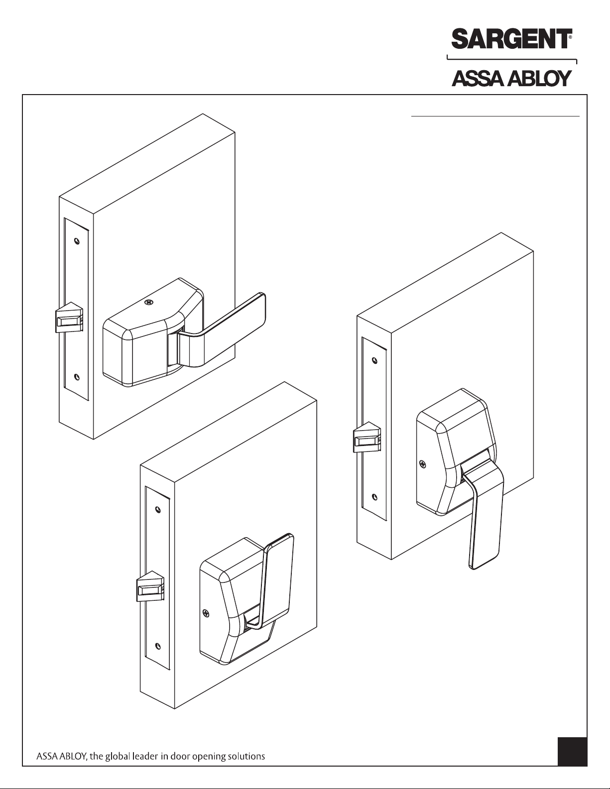
INSTALLATION INSTRUCTIONS
7800 MORTISE LOCK WITH PT PADDLE TRIM
FOR INSTALLATION ASSISTANCE, CALL SARGENT AT 1-800-727-5477 • www.sargentlock.com
TOOLS REQUIRED
• Phillips screwdriver #2
• Drill
• 7/46" Drill Bit (Wood Door)
• #8-32 Tap (Metal Door)
• 0.136" (#18) Tap Drill
• Screw Pack with screws for lockbody,
fronts & strike screws (part # 77-4236)
• T15 torx bit
• 1/8" Allen key
Copyright © 2011, Sargent Manufacturing Company, an ASSA ABLOY Group company.
All rights reserved. Reproduction in whole or in part without the express written
permission of Sargent Manufacturing Company is prohibited.
A8130C
1
Page 2
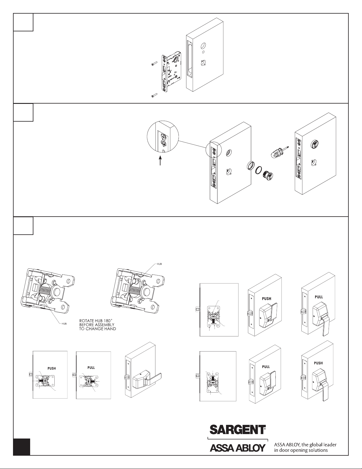
1
INSTALLATION OF LOCK
• Slide lock into the door
• Secure lock in door with (2) wood screws
#12 x 1-1/4" or machine screws #12-24 x 1/2"
• Do not tighten screws fully at this point
2
INSTALLATION OF CYLINDER
* For non-cylinder functions proceed to STEP 3
• Thread the cylinder into the lockbody
• Verify the cylinder is flush with the collar and the
name is horizontal
• Secure cylinder with cylinder clamping screw
located above the deadbolt opening
• Verify the cylinder functions correctly
3
DETERMINE ORIENTATION AND HANDING OF TRIM
• The trim can be mounted vertically or horizontally
*NOTE: Chassis is packed with paddle attached
Remove paddle before installing
Note that the lock front
screws are not fully
tightened, screws will
be tightened once trim
is installed
Install Cylinder
Vertical Mounting
Tighten Cylinder
Clamping Screw
Outside of door
Horizontal Mounting
THRU
SPRING
BOLT
CHASSIS
THRU
BOLT
THRU
BOLT
CHASSIS
THRU
BOLT
SPRING
To change from PUSH to PULL orientation, chassis will need
to be turned 180° and paddle installed in the correct direction
*NOTE: Before installing chassis to door, make sure
spring orientation is correct
Copyright © 2011, Sargent Manufacturing Company, an ASSA ABLOY Group company.
2
A8130C
All rights reserved. Reproduction in whole or in part without the express written
permission of Sargent Manufacturing Company is prohibited.
CHASSIS
THRU
BOLT
SPRING
CHASSIS
SPRING
THRU
BOLT
THRU
BOLT
THRU
BOLT
Page 3

4
INSTALLATION OF CHASSIS
• Check handing of chassis before installing mounting screws
• Insert the (2) mounting posts through the outside chassis,
then secure with (2) #8-32 x 5/8" machine screws through
the inside chassis
Do not tighten fully at this point
• Lockbody screws on edge of door are to be securely fastened
at this point
• Level chassis
• Tighten thru bolt screws
• Attach the outside front plate to lock front with (2) #8-32 x 1/4"
flat head screws
• Tighten all screws firmly, be sure not to over tighten
Machine
Screws
Thru
Bolt
5
INSTALLATION OF PADDLES AND COVERS
• Insert paddle in slot
• Install set screw
• Slide cover over paddle and align with mounting holes
• Install cover screws
Set screw
1/8" Allen key
CHASSIS
UP POSITION
PADDLE
(2) Torx cover screws
T15 torx bit
DOWN POSITION
PADDLE
Copyright © 2011, Sargent Manufacturing Company, an ASSA ABLOY Group company.
All rights reserved. Reproduction in whole or in part without the express written
permission of Sargent Manufacturing Company is prohibited.
Cover
A8130C
3
Page 4

7800PT MULTI FUNCTION LOCK INSTRUCTIONS
36
05
37
38
04 06 13 17 31
CHECK HUB
HUB
INSIDE
INSIDE
OUTSIDE
OUTSIDE
LEFT HAND
LEFT HAND
REVERSE
BEVEL
RIGHT HAND
RIGHT HAND
REVERSE
BEVEL
DOOR HANDS DETERMINED FROM OUTSIDE
DOOR HANDING
How to Change Function of Lock:
Green catch screw must be located as designated on lock case to create desired function.
3 locations: One for 05, 37 & 38 functions (15 function in unlocked position)
One for 04, 06, 13, 17 & 31 functions
And one for 36 function
Note: When moving green catch screw to 04, 06, 13, 17 & 31 functions, hub
position must be at 45° as shown on lockcase.
Note: 17 function requires both levers to be rigid. Rotate red locking piece 90°,
so red surface of slide faces back of lockbody.
7800PT lockbody is required when using PT paddle trim, 8200 lever lockbody
will not function properly with the PT trim.
Items needed to create each of the following functions:
Function
04 X X X
05 X X X X***
06 X X X
13 X X
17 X X X X
31 X X X
36 X X X
37 X X X
38 X X X X
Outside
Lever
Inside
Lever
Trim One
Side Kit
Outside
Cylinder
Inside
Cylinder
Thumb
Turn
#41 Cylinder is standard for both single & double cylinder
functions for 1-3/4" thick door
NOTE: Trim-one-side functions always require an
inside trim assembly which can be used on the inside
or outside of the door
U.S. Patent (Pending) No. 5,678,870
How To Change Hand of Lock
Note: Red surface of locking piece must face secure
(keyed/locked) side of door.
To rotate locking piece:
1. Position lockbody with red surface of locking piece visible.
2. Insert blade type screwdriver into locking piece slot to rotate
locking piece.
3. Push locking piece toward back of lock body and rotate 180°
until RED surface shows on opposite side.
IMPORTANT: 04, 06, 13, 17 and 31 Functions require:
(a) Green catch screw
to be removed
(b) Rotate hub 45°
to vertical position
(c) Rotate locking piece
for required hand
(d) Red surface faces
locked side of door
(e) Rotate hub to the
original 45° position
as shown on lockcase
(f) Green catch screw is
then reinstalled
4
A8130C
Copyright © 2011, Sargent Manufacturing Company, an ASSA ABLOY Group company.
All rights reserved. Reproduction in whole or in part without the express written
permission of Sargent Manufacturing Company is prohibited.
Locking
piece
slot
Red color
indicates locked
side of door or
hold back side
(91 and 92
Functions)
Note: Beveled surface of latch must face strike. The deadlatch
is self adjusting. To change hand of latch:
1. Insert screwdriver blade into
the spade shaped slot
2. Rotate screwdriver 90º to push latch out until back of latch
clears lock front. Then rotate latch 180º. Latch will then re-enter
lockbody. (Note: Latch can not be unscrewed)
 Loading...