

Page 1
Replacement Instructions
1
57/59- Prefix 80 Series Exit Device
PCB Module Assembly
Replacement Instructions
Prefix Part
Number
59- 52-4837 Standard
59- BC- 52-4838 BOCA (30 seconds)
57- 52-4830 Standard
57- BC- 52-4831 BOCA (30 seconds)
Description
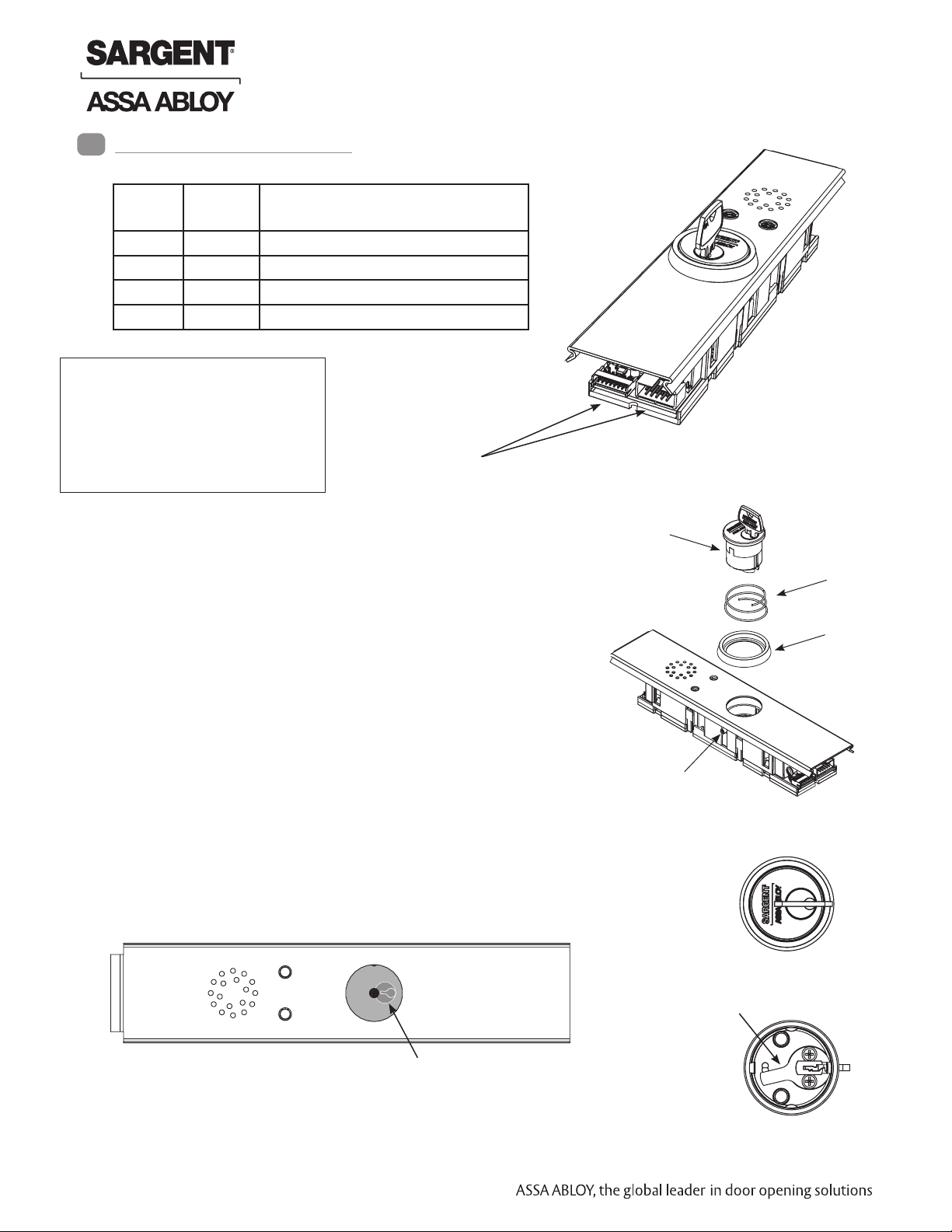
PCB Module Assembly Replacement
NOTE: Use caution when
removing insert assembly
to avoid damaging the rail
harness connected to the
PCB module assembly.
1. Ensure power to device is disconnected.
2. Carefully disconnect all connectors (Fig. 1).
3. Remove insert assembly from rail mounting assembly.
4. Loosen set screw by turning counter-clockwise using
5/64” allen wrench.
5. Extract and slide cylinder through spring and collar.
Connector Locations
Insert Assembly
Fig. 1
Cylinder with Key
Spring
Collar
When replacing cylinder, slide cylinder through spring
then collar, taking care to orient cylinder as shown.
Cylinder Orientation
See illustration on circuit board for correct orientation of
cylinder/cam when installing.
Note that proper position of cam allows for removal of key.
Top View with cylinder removed
Illustration (on circuit board)
Copyright © 2013, Sargent Manufacturing Company, an ASSA ABLOY Group company. All rights reserved.
Reproductions in whole or in part without express written permission of Sargent Manufacturing Company is prohibited.
10/31/13
1 1-800-810-WIRE • www.sargentlock.com • A8184A
Set Screw
Top of Cylinder
Cylinder Cam
Bottom of Cylinder
Page 2
57/59- Prefix 80 Series Exit Device
PCB Module Assembly
Replacement Instructions
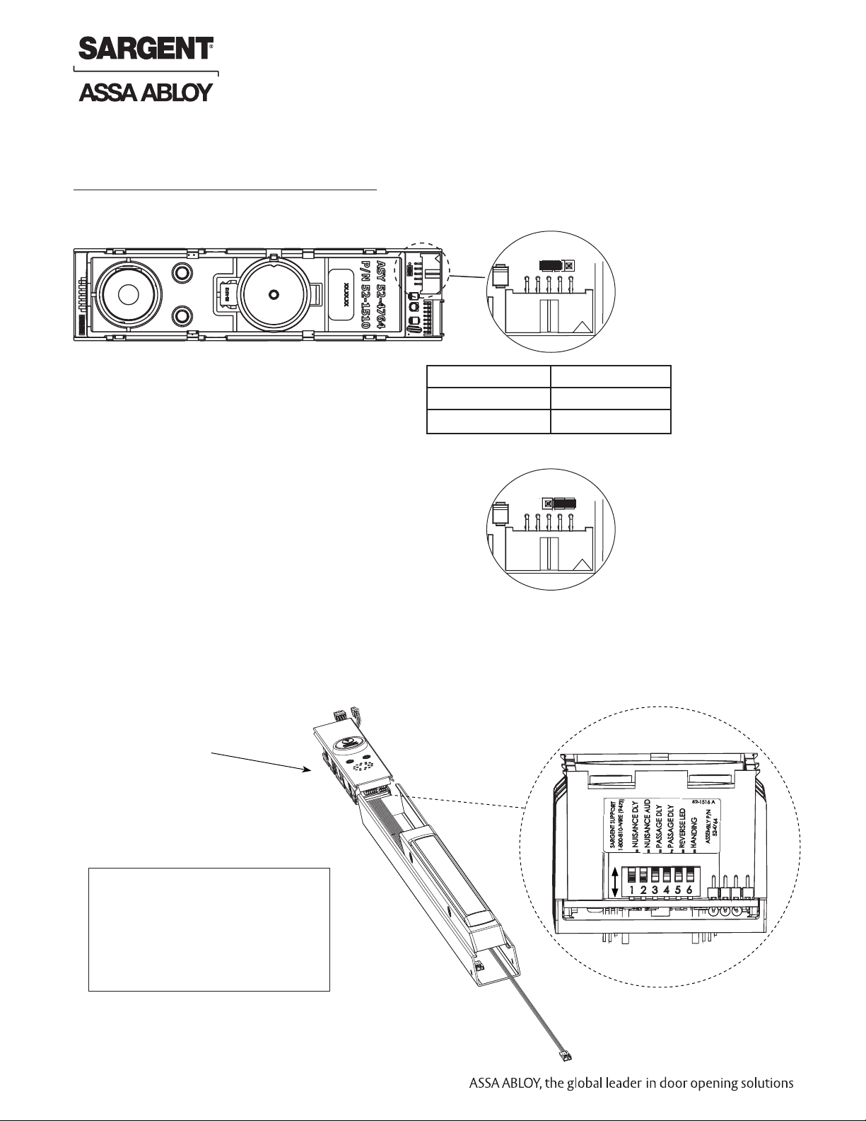
NOTES
With Rim, Mortise and Vertical Rod exit devices:
When jumper is missing or in wrong position, the Yellow Diagnostic LED turns ON. To locate (J5) jumper,
remove Insert Assembly and Insert Assembly Plate:
1 2 3
J5
FUNCTION JUMPER
57- J5-1 & J5-2
59-STD J5-2 & J5-3
Default factory setting
for 57- shown
1 2 3
J5
Default factory setting
for 59- shown
Dip Switch Settings
Installer should note DIP switch settings of module being replaced to ensure
same settings are made for replacement module.
Insert Assembly
S2
OFF
NOTE: Use caution when
ON
removing insert assembly
to avoid damaging the rail
harness connected to the
PCB module assembly.
Copyright © 2013, Sargent Manufacturing Company, an ASSA ABLOY Group company. All rights reserved.
Reproductions in whole or in part without express written permission of Sargent Manufacturing Company is prohibited.
10/31/13
2 1-800-810-WIRE • www.sargentlock.com • A8184A
Page 3

57/59- Prefix 80 Series Exit Device
PCB Module Assembly
Replacement Instructions
S2-1 Nuisance Delay - (Field selectable 0 or 1 second) A one second nuisance delay can be enabled by setting Dip Switch
(S2-1) to the “On” position. When nuisance delay is enabled, the unit will require the push bar to be depressed for
more than one second in order to trigger an irreversible alarm condition. If the push bar is released before the 1 second
has elapsed, the unit will go back into the “delayed egress mode” and the alarm will not sound. Nuisance delay is set
to “On” position at factory.
If the Dip Switch S2-1 is in the “Off” position, there will be no nuisance delay and alarm horn will sound immediately
when the push bar is depressed.
S2-2 Nuisance Audible - (Field selectable on or off) An audible horn is enabled by setting Dip Switch S2-2 to the “On”
position. The internal horn will sound as soon as the push bar is depressed, signaling that the device is armed. If the
pushbar is held down for more than 1 second, an irreversible alarm condition begins. If Dip Switch S2-2 is in the “Off”
position, the horn will not sound during nuisance delay.
Nuisance audible is set to “On” position at factory to sound horn when rail is depressed during nuisance delay.
S2-1
S2-4
5 6
5 6
OFF
ON
OFF
ON
5 6
S2-2
5 6
S2 Dip Switch Position
S2-3
OFF
OFF
ON
ON
S2-4
OFF
ON
OFF
ON
Momentary Egress
Time
5 seconds (Default)
10 seconds
20 seconds
40 seconds
S2-1 On - (1) second Nuisance Delay
S2-1 Off - No Nuisance Delay
S2-2 On - Nuisance Audible On
S2-2 Off - Nuisance Audible Off
S2-3 & S2-4 Momentary Egress Time Used to select the momentary egress time
of 5, 10, 20 or 40 seconds. This switch is
preset at the factory for five seconds.
S2-3
OFF
ON
OFF
ON
S2-5 Reverse LED - Field selectable green or red. When S2-5 is “Off” the exit device LED is green when in armed
mode (default) and red when in maintained or momentary egress mode. When S2-5 is “On” the exit device
LED is red when in armed mode and green when in maintained or momentary egress.
S2-5
S2-5 On - Red (Armed); Green (maintained or momentary egress)
S2-5 Off - Green (Armed); Red (maintained or momentary egress)
OFF
ON
5 6
S2-6 Handing - Field selectable LHRB or RHRB. For a LHRB exit device S2-6 is “Off” for the top LED on the insert
to be used when the device is armed. For a RHRB exit device S2-6 is “On” for the top LED on the insert to be
used when the device is armed.
Copyright © 2013, Sargent Manufacturing Company, an ASSA ABLOY Group company. All rights reserved.
Reproductions in whole or in part without express written permission of Sargent Manufacturing Company is prohibited.
10/31/13
S2-6 Off - LHRB; Top LED indicates “Armed”
S2-6 On - RHRB; Top LED indicates “Armed”
OFF
ON
3 1-800-810-WIRE • www.sargentlock.com • A8184A
S2-6
5 6
 Loading...