

Page 1
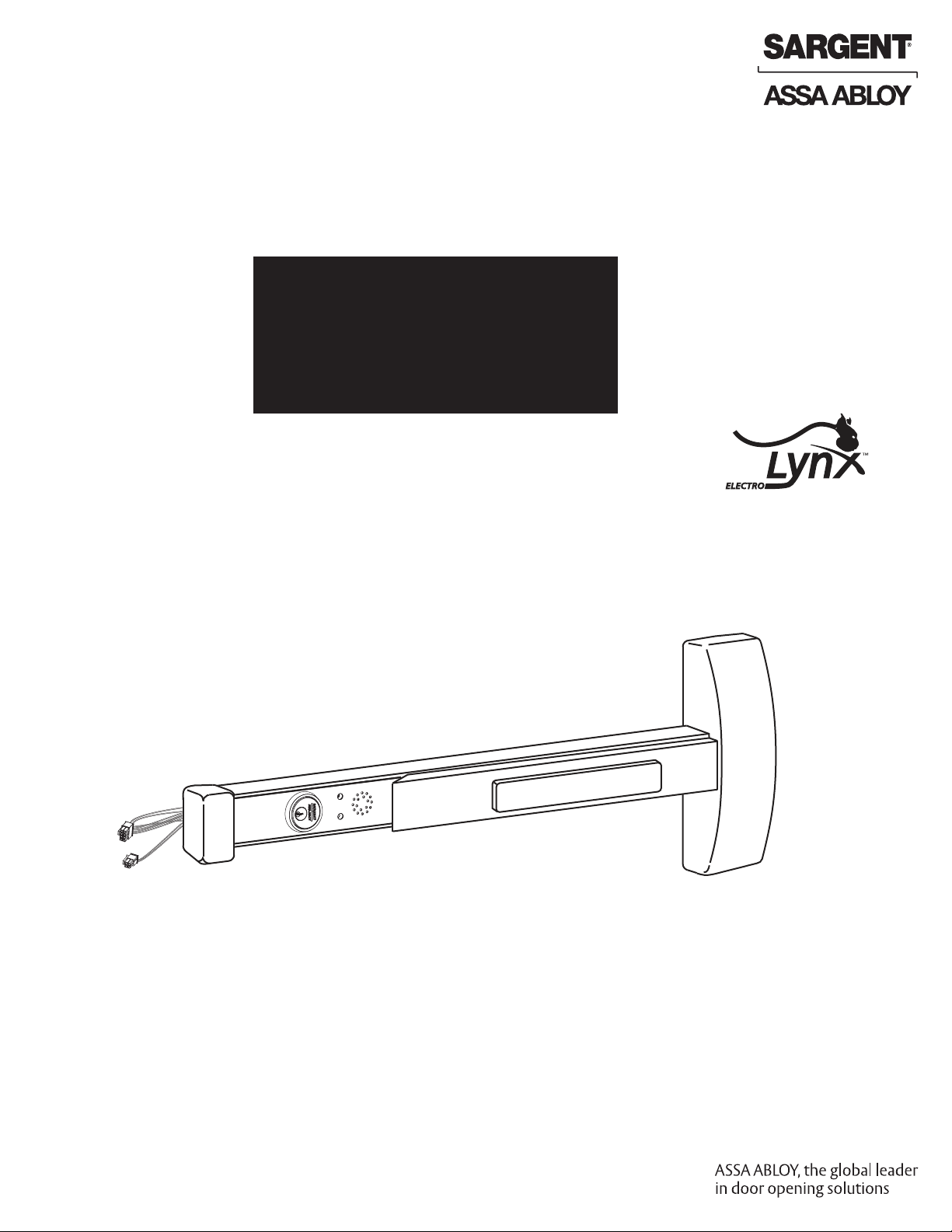
57-
Delayed Egress
Exit Device
Installation Instructions
For installation assistance, contact SARGENT at 800-810-WIRE (9473)
A7743C
04/13
Copyright 2013, Sargent Manufacturing Company, an ASSA ABLOY Group company.
All rights reserved. Reproduction in whole or in part without the express written
permission of Sargent Manufacturing Company is prohibited.
Page 2
Table of Contents
1
Warning................................................................ 3
2
General Description.................................................. 4
3
Parts Breakdown...................................................... 4
4
Installation Instructions............................................. 5
5
Factory Default Settings............................................. 9
6
57- Dip Switch Settings.............................................10
7
57- Wiring............................................................ 11
8
Exit Device Plug-in Connector Installation.......................14
9
System Wiring Examples.......................................... 15
10
Operating Instructions.............................................. 18
11
Troubleshooting...................................................... 21
®
®
is a registered trademark of ASSA ABLOY, Inc.
A7743C
04/13
ElectroLynx
As part of their promise to provide innovative, fast and
effective, and higher security solutions to their customers,
ASSA ABLOY Group companies offer ElectroLynx, a universal
quick-connect system that simplifies the electrification of the
door opening.
ElectroLynx
Copyright 2013, Sargent Manufacturing Company, an ASSA ABLOY Group company.
All rights reserved. Reproduction in whole or in part without the express written
permission of Sargent Manufacturing Company is prohibited.
Page 3
1
Warning
Changes or modifications to this device not expressly approved by ASSA ABLOY
could void the user’s authority to operate the equipment.
FCC:
This equipment has been tested and found to comply with the limits for a Class B digital device, pursuant to Part
15 of the FCC Rules. These limits are designed to provide reasonable protection against harmful interference in a
residential installation. This equipment generates, uses, and can radiate radio frequency energy and, if not installed
and used in accordance with the instructions, may cause harmful interference to radio communications. However,
there is no guarantee that interference will not occur in a particular installation. If this equipment does cause harmful
interference to radio or television reception, which can be determined by turning the equipment off and on, the user
is encouraged to try to correct the interference by one or more of the following measures:
• Reorient or relocate the receiving antenna.
• Increase the separation between the equipment and receiver.
• Connect the equipment into an outlet on a circuit different from that to which the receiver is connected.
• Consult the dealer or an experienced radio/TV technician for help.
Industry Canada:
This Class B digital apparatus meets all requirements of the Canadian Interference Causing Equipment Regulations.
Operation is subject to the following two conditions: (1) this device may not cause harmful interference, and (2) this
device must accept any interference received, including interference that may cause undesired operation.
Cet appareillage numérique de la classe B répond à toutes les exigences de l’interférence canadienne causant des
règlements d’équipement. L’opération est sujette aux deux conditions suivantes: (1) ce dispositif peut ne pas causer
l’interférence nocive, et (2) ce dispositif doit accepter n’importe quelle interférence reçue, y compris l’interférence qui
peut causer l’opération peu désirée.
“This equipment complies with FCC radiation exposure limits set forth for an uncontrolled environment. This
equipment should be installed and operated with minimum distance 20cm between the radiator and your body. This
transmitter must not be co-located or operating in conjunction with any other antenna or transmitter.”
Under Industry Canada regulations, this radio transmitter may only operate using an antenna of a type and maximum
(or lesser) gain approved for the transmitter by Industry Canada. To reduce potential radio interference to other
users, the antenna type and its gain should be so chosen that the equivalent isotropically radiated power (e.i.r.p.) is
not more than that necessary for successful communication.
Conformément à la réglementation d’Industrie Canada, le présent émetteur radio peut fonctionner avec une antenne
d’un type et d’un gain maximal (ou inférieur) approuvé pour l’émetteur par Industrie Canada. Dans le but de réduire
les risques de brouillage radioélectrique à l’intention des autres utilisateurs, il faut choisir le type d’antenne et son
gain de sorte que la puissance isotrope rayonnée équivalente (p.i.r.e.) ne dépasse pas l’intensité nécessaire à
l’établissement d’une communication satisfaisante.
Any retrofit or other field modification to a fire rated opening can potentially impact the fire rating of the opening,
and SARGENT Manufacturing makes no representations or warranties concerning what such impact may be in
any specific situation. When retrofitting any portion of an existing fire rated opening, or specifying and installing a
!
new fire-rated opening, please consult with a code specialist or local code official (Authority Having Jurisdiction) to
ensure compliance with all applicable codes and ratings.
Copyright © 2013, Sargent Manufacturing Company, an ASSA ABLOY Group company. All rights reserved.
Reproductions in whole or in part without express written permission of Sargent Manufacturing Company is prohibited.
04/15/13
3
1-800-810-WIRE • www.sargentlock.com • A8151B
Page 4
57- Prefix 80 Series Exit Device
General Description
2
The SARGENT 57-Delayed Egress Exit Device is designed to work with an external electromagnetic lock in areas that require a delayed egress which alarms at the door when any attempt is made to violate the door.
The 57- device can be tied into a fire alarm system.
NOTE: Proper connections and appropriate peripheral hardware are required.
BC-Prefix Option
The BC prefix for 57- indicates that the unit has been programmed to comply with the section of the BOCA code
relating to delayed egress.
BOCA allows for automatic reset of the delayed egress unit. Under BOCA, the unit can automatically reset thirty (30)
seconds after the door has been cycled. If the door is opened any time during the thirty (30) seconds, the timer in the
unit resets and waits another thirty (30) seconds before rearming. This requires a door position switch.
Note: If a door position switch is not used (Blue wire connected to Black wire), the unit will automatically reset in
30 seconds.
Electrical Specifications
• Input Voltage: 24VDC regulated/filtered
• Power Consumption: 100 mA Unloaded (typical/standard), 375 mA Loaded (with Optional features)
• Operating Temp: 0°C to 49°C (32°F to 120°F)
• Maximum Electromagnetic Lock load: 275mA. If desired load exceeds this limit, an external relay
module may be used.
All components must be installed according to prevailing electrical codes.
There are no user serviceable parts on the 57- PCB module assembly.
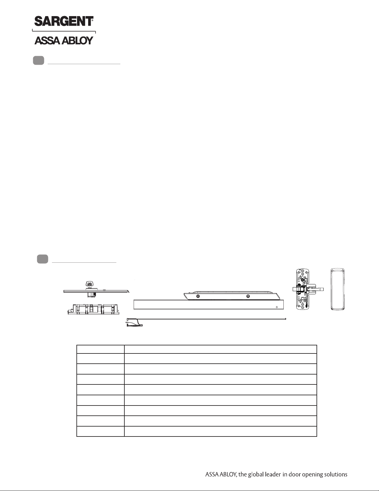
Parts Breakdown
3
PCB Module
Assembly
Part No. Description
Consult factory Rail Assembly
Consult factory Chassis Assembly
Consult factory Insert Assembly
Consult factory Chassis Cover
Insert
Assembly
52-4810 Harness Assembly - “E” and “F” size rails
52-4811 Harness Assembly - “J” and “G” size rails
52-4830 PCB Module Replacement Pack - Standard
52-4831 PCB Module Replacement Pack - BOCA (BC prefix)
Rail Assembly
Harness
Assembly
Chassis
assembly
Chassis
Cover
Copyright © 2013, Sargent Manufacturing Company, an ASSA ABLOY Group company. All rights reserved.
Reproductions in whole or in part without express written permission of Sargent Manufacturing Company is prohibited.
04/15/13
4 1-800-810-WIRE • www.sargentlock.com • A7743C
Page 5
57- Prefix 80 Series Exit Device
Installation Instructions
4
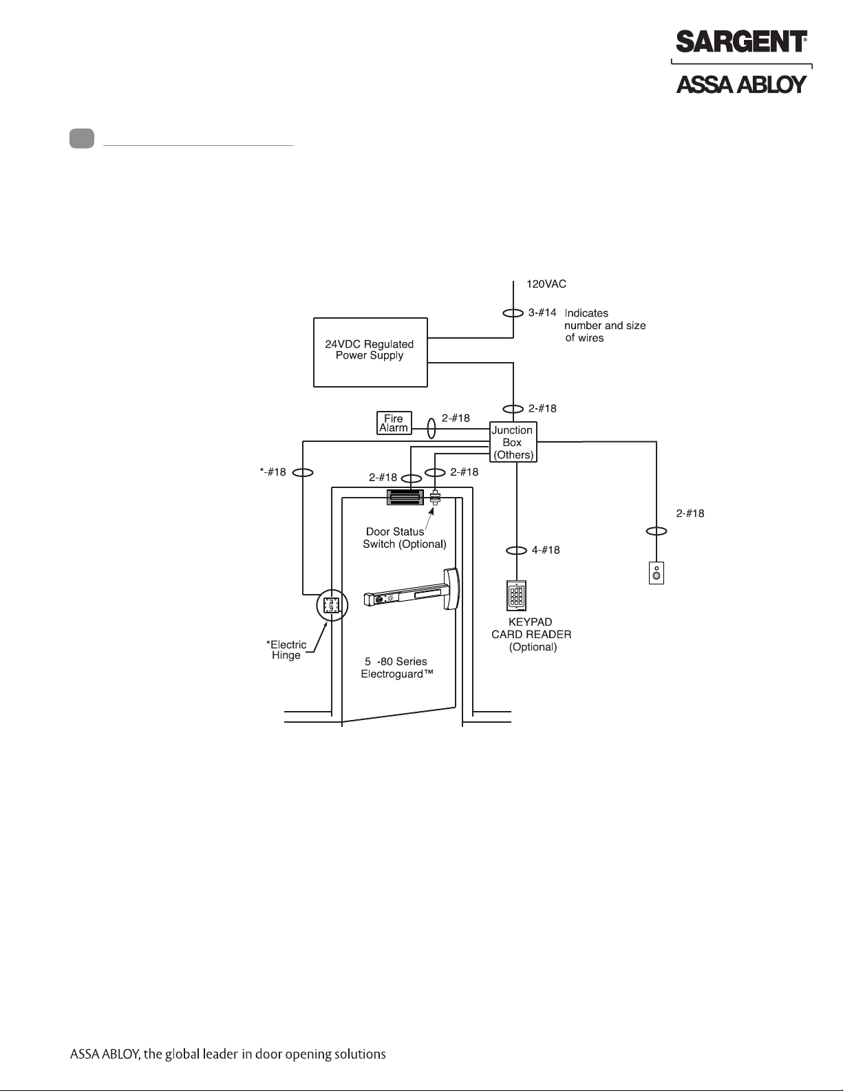
1. Determine locations of components at the door
2. Mount all hardware and peripheral equipment according to manufacturer’s instructions
NOTE: For exit device mechanical installation, refer to mechanical instruction sheets and
templates included with product.
3. Power supply should be mounted near door to avoid power drop due to excessive wire runs
4. Features used will determine wire requirements of electric hinge or other power transfer*
Sample Elevation Diagram
Electromagnetic
Lock
2
31
54 6
8
7 9
0 #
*
SARGENT
REMOTE RESET
(Optional)
7
*Refer to specific mechanical instructions for proper installation of 57- 80
Series exit devices.
1-800-810-WIRE • www.sargentlock.com • A7743C 5
Copyright © 2013, Sargent Manufacturing Company, an ASSA ABLOY Group company. All rights reserved.
Reproductions in whole or in part without express written permission of Sargent Manufacturing Company is prohibited.
04/15/13
Page 6
57- Prefix 80 Series Exit Device
Installation Instructions (Continued)
4
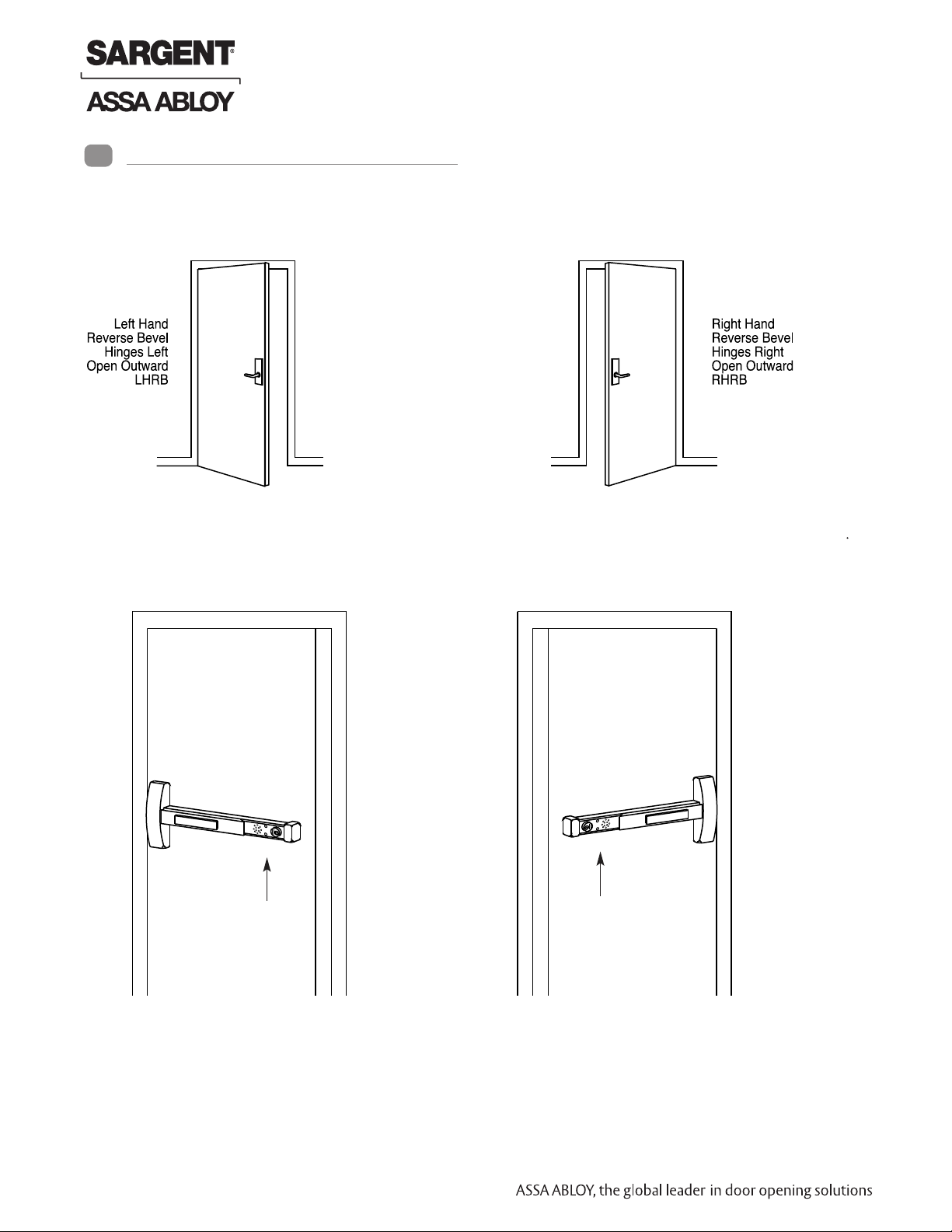
Verify hand and bevel of door. Exit devices are always reverse bevel and are mounted on the inside of the door.
Outside View
On inside of door, exit devices are oriented as follows:
Outside view
8800 LHRB shown
Lights from top to bottom:
Green, Red (Default)
Inside View
All subsequent illustrations in this document are shown as RHRB
Copyright © 2013, Sargent Manufacturing Company, an ASSA ABLOY Group company. All rights reserved.
Reproductions in whole or in part without express written permission of Sargent Manufacturing Company is prohibited.
04/15/13
6 1-800-810-WIRE • www.sargentlock.com • A7743C
8800 RHRB shown
Lights from top to bottom:
Green, Red (Default)
Inside view
Page 7
Installation Instructions (Continued)
4
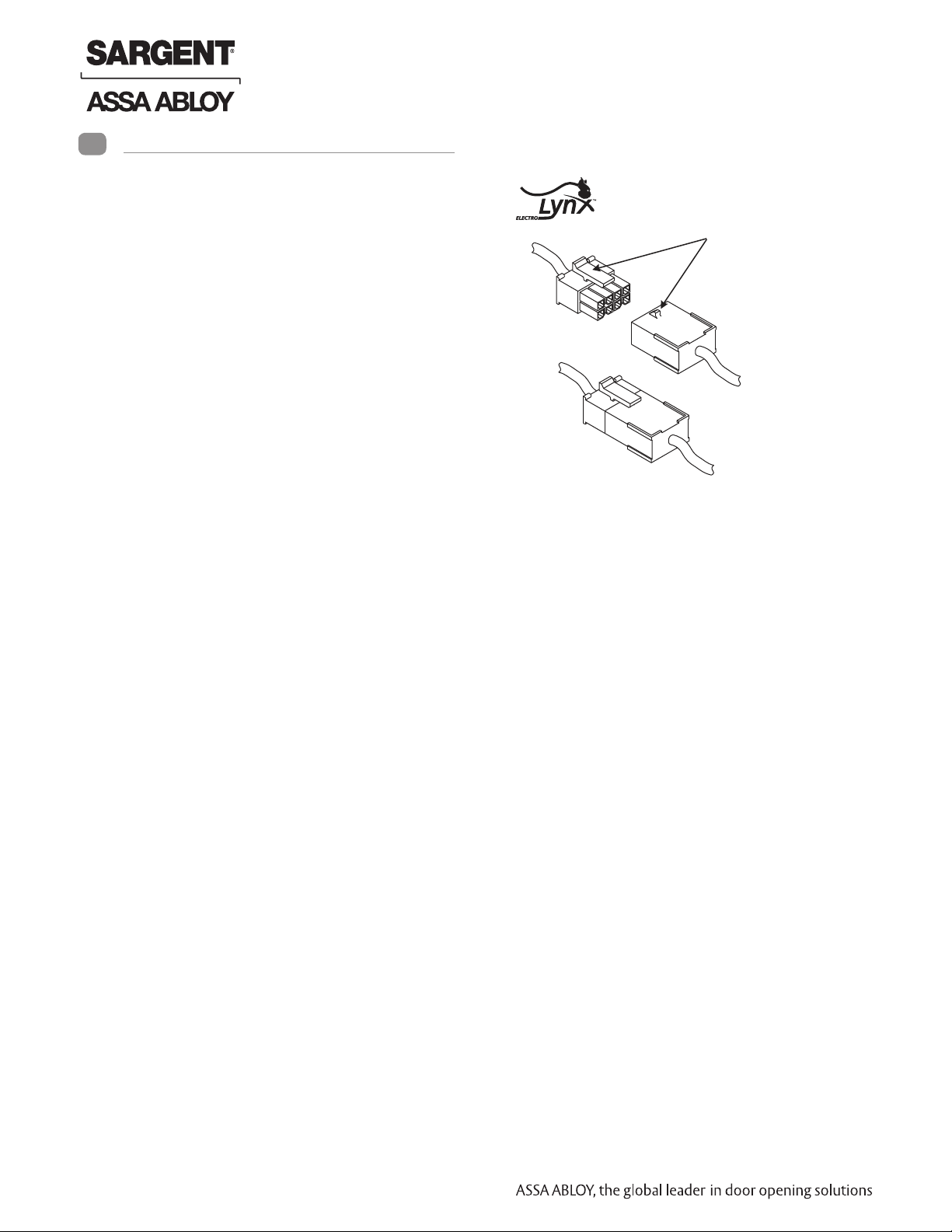
ElectroLynx® Connector System Notes:
The system is designed to be installation friendly with
pluggable connectors from the electric hinge through
the door to the rail. The only wiring required is to the
flying leads on the pigtail harness assembly on the
frame side of the electric hinge.
IMPORTANT:
The plug and receptacle connectors are designed
to mate and lock together as shown in the figure.
Plug the connectors into each other with the locking
mechanism aligned as indicated.
Do NOT force connectors on any other way
57- Prefix 80 Series Exit Device
Locking mechanism
Plug
Receptacle
57- Exit Device - ElectroLynx Wiring Notes (Consult factory for assistance if required)
1. The ElectroLynx connector system is designed to be installation friendly with pluggable connectors from the
electric hinge through the door to the rail. The rail, raceway, electric hinge, and pigtail harness connector
terminations and wire colors all match.
2. For most applications, an 8-pin electric hinge is required.
3. Plug raceway connectors into ElectroLynx hinge connectors. Hard wire to corresponding pigtail harness wires
as required.
Installation Notes:
1. With new applications, a raceway harness with 8 & 4-pin connectors will be pre-installed inside the door by
ASSA ABLOY door manufacturer when specified during the ordering process. Raceway harness kits are also available
for retrofit applications. (For retrofit applications, refer to retrofit instructions)
2. If door does not have a raceway harness with connectors, either consult factory for raceway retrofit kit or cut
connectors off product and hard wire, as required.
3. Wiring to pigtail harness is per facility wiring requirement.
The rail, raceway, electric hinge and pigtail connector ( - +) terminations and wire colors all match.
Copyright © 2013, Sargent Manufacturing Company, an ASSA ABLOY Group company. All rights reserved.
Reproductions in whole or in part without express written permission of Sargent Manufacturing Company is prohibited.
04/15/13
7 1-800-810-WIRE • www.sargentlock.com • A7743C
Page 8
57- Prefix 80 Series Exit Device
Installation Instructions (Continued)
4
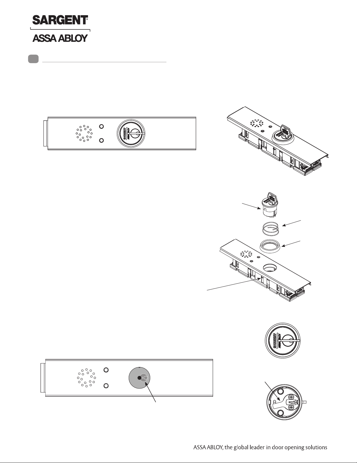
Cylinder Installation
1. Prepare door according to template(s) and instructions supplied with exit device.
2. Verify cylinder (size varies; consult factory) is installed in rail insert with collar prior to installing
exit device on door.
Top View of Insert
To Remove/Replace Cylinder
1. Ensure power is disconnected.
2. Loosen set screw by turning counter-clockwise using
5/64” allen wrench.
3. Extract and slide cylinder through spring and collar.
When replacing cylinder, slide cylinder through spring
then collar, taking care to orient cylinder as shown
Set Screw
Cylinder Orientation
See illustration on circuit board for correct orientation of
cylinder when installing.
Note that proper position of cam allows for removal of key.
Side View
Cylinder with Key
Spring
Collar
Top View with cylinder removed
Illustration (on circuit board)
Copyright © 2013, Sargent Manufacturing Company, an ASSA ABLOY Group company. All rights reserved.
Reproductions in whole or in part without express written permission of Sargent Manufacturing Company is prohibited.
04/15/13
8 1-800-810-WIRE • www.sargentlock.com • A7743C
Top of Cylinder
Cylinder Cam
Bottom of Cylinder
Page 9

57- Prefix 80 Series Exit Device
Factory Default Settings
5
Default factory presets for the 57- are as follows:
Status LEDs/Time Horn
Armed (Delayed Egress) Solid GREEN Off
Momentary Egress (Passage Delay) Flashing RED for (5) seconds Off
Disarmed Solid RED Off
Alarm Flashing RED & GREEN (15)
On
seconds for egress
Nuisance Delay (1) second On
Nuisance Audible On
Momentary Egress Time (5) seconds
Reverse LED RED (Armed)
Handing ”Top” LED (Armed) for
LHRB or RHRB
If default feature settings need to be changed, carefully slide the insert assembly
from the rail assembly to make the proper DIP switch adjustments (see Section 5
- DIP Switch Settings).
For example, solid RED can be set to indicate that the rail is ”Armed” with solid
GREEN indicating that rail is ”Disarmed”.
Insert Assembly
NOTE: Use caution when
removing insert assembly
to avoid damaging the rail
harness connected to the
PCB module assembly.
Copyright © 2013, Sargent Manufacturing Company, an ASSA ABLOY Group company. All rights reserved.
Reproductions in whole or in part without express written permission of Sargent Manufacturing Company is prohibited.
04/15/13
9 1-800-810-WIRE • www.sargentlock.com • A7743C
S2
OFF
ON
Page 10

57- Prefix 80 Series Exit Device
57- Dip Switch Settings
6
S2-1 Nuisance Delay - (Field selectable 0 or 1 second) A one second nuisance delay can be enabled by setting Dip
Switch (S2-1) to the “On” position. When nuisance delay is enabled, the unit will require the push bar to be depressed for more than one second in order to trigger an irreversible alarm condition. If the push bar is released before the 1 second has elapsed, the unit will go back into the “delayed egress mode” and the alarm will not sound.
Nuisance delay is set to “On” position at factory.
If the Dip Switch S2-1 is in the “Off” position, there will be no nuisance delay and alarm horn will sound immediately when the push bar is depressed.
S2-2 Nuisance Audible - (Field selectable on or off) An audible horn is enabled by setting Dip Switch S2-2 to the “On”
position. The internal horn will sound as soon as the push bar is depressed, signaling that the device is armed. If
the pushbar is held down for more than 1 second, an irreversible alarm condition begins. If Dip Switch S2-2 is in
the “Off” position, the horn will not sound during nuisance delay.
Nuisance audible is set to “On” position at factory to sound horn when rail is depressed during nuisance delay.
S2-1
S2-4
5 6
5 6
OFF
ON
OFF
ON
5 6
S2-2
5 6
S2 Dip Switch Position
S2-3
OFF
OFF
ON
ON
S2-4
OFF
ON
OFF
ON
Momentary Egress
Time
5 seconds (Default)
10 seconds
20 seconds
40 seconds
S2-1 On - (1) second Nuisance Delay
S2-1 Off - No Nuisance Delay
S2-2 On - Nuisance Audible On
S2-2 Off - Nuisance Audible Off
S2-3 & S2-4 Momentary Egress Time Used to select the momentary egress time
of 5, 10, 20 or 40 seconds. This switch is
preset at the factory for five seconds.
S2-3
OFF
ON
OFF
ON
S2-5 Reverse LED - Field selectable green or red. When S2-5 is “Off” the exit device LED is green when in armed
mode (default) and red when in maintained or momentary egress mode. When S2-5 is “On” the exit device
LED is red when in armed mode and green when in maintained or momentary egress.
S2-5
S2-5 On - Red (Armed); Green (maintained or momentary egress)
S2-5 Off - Green (Armed); Red (maintained or momentary egress)
OFF
ON
5 6
S2-6 Handing - Field selectable LHRB or RHRB. For a LHRB exit device S2-6 is “Off” for the top LED on the insert
to be used when the device is armed. For a RHRB exit device S2-6 is “On” for the top LED on the insert to be
used when the device is armed.
Copyright © 2013, Sargent Manufacturing Company, an ASSA ABLOY Group company. All rights reserved.
Reproductions in whole or in part without express written permission of Sargent Manufacturing Company is prohibited.
04/15/13
S2-6 Off - LHRB; Top LED indicates “Armed”
S2-6 On - RHRB; Top LED indicates “Armed”
OFF
ON
10 1-800-810-WIRE • www.sargentlock.com • A7743C
S2-6
5 6
Page 11

57- Prefix 80 Series Exit Device
57- Wiring
7
A. IMPORTANT
Caution: Disconnect all input power before beginning installation to prevent electrical
shock and equipment damage
1. Installer must be a trained, experienced service person
2. All wiring must comply with applicable local electrical codes, ordinances and regulations
3. Field cut rail assemblies are not allowed. Exit device must be ordered for specific door width.
Ground ring terminal
4, Green (EG)
2
4
8
3
7 6 5
1
1, Black (-Return)
2, Red (+24)
3, White RR
5, Orange (EI)
6, Blue (DS)
7, Brown (Mag-)
8, Red (Mag+)
2
4
3
1
Note: 55- option only*
2, Blue (C)
3, Brown (NO)
4, Yellow (NC)
Electroguard (57-, 19-57-)
80 Series Rail
Legend
EI = External Inhibit
DS = Door Status Switch
EG = Earth Ground
NO = Normally Open
NC = Normally Closed
RR = Remote Reset
C = Common
B. Installation Notes:
1. With new applications, a raceway harness with 8 & 4-pin connectors will be pre-installed inside the door by
ASSA ABLOY door manufacturer when specified during the ordering process. Raceway harness kits are also available
for retrofit applications. (For retrofit applications, refer to retrofit instructions)
2. If door does not have a raceway harness with connectors, either consult factory for raceway retrofit kit or cut
connectors off product and hard wire, as required.
3. Wiring to pigtail harness is per facility wiring requirement.
The rail, raceway, electric hinge and pigtail connector ( - +) terminations and wire colors all match.
4. *55- only (option) Switch contact rating: 2A @ 30VDC
5. Tape or cap off ends of unused pigtail wires (not shown) to ensure that they do not short.
Copyright © 2013, Sargent Manufacturing Company, an ASSA ABLOY Group company. All rights reserved.
Reproductions in whole or in part without express written permission of Sargent Manufacturing Company is prohibited.
04/15/13
11 1-800-810-WIRE • www.sargentlock.com • A7743C
Page 12

57- Prefix 80 Series Exit Device
57- Wiring (Continued)
7
The following are the input and output connector designations.
Harness Circuit
Connector Board Input/ Harness Function
Pin No.* Pin No. Output Wire Color
8-2 J1-1 input Red +24VDC power
8-1 J1-2 input Black -Return
8-3 J1-4 input White
8-5 J1-5 input Orange External inhibit - disarm unit from
8-6 J1-6 input Blue Door position sensor (Door Status/Monitor)
8-4 Chassis Ground Green ESD (Earth) Ground
8-7 J1-8 output Brown -Return Magnet -
8-8 J1-10 output Red +24VDC Magnet
*Example: 8-2 is the 8-pin connector position #2
N.O.
N.O.
Remote Reset
i/s or o/s (key switch, card reader, keypad)
N.C.
Copyright © 2013, Sargent Manufacturing Company, an ASSA ABLOY Group company. All rights reserved.
Reproductions in whole or in part without express written permission of Sargent Manufacturing Company is prohibited.
04/15/13
12 1-800-810-WIRE • www.sargentlock.com • A7743C
Page 13

57- Prefix 80 Series Exit Device
57- Wiring (Continued)
7
Harness I/O Circuit
Connector Board Function
Pin No. Pin No.
8-2 J1-1 24VDC Power Supply Input (+)
This input may be tied to the normally closed contact of a building’s fire alarm system.
If the fire alarm is activated, this contact will open, voiding the 15 second delay for egress.
8-1 J1-2 Return - Power Supply -return (-).
8-3 J1-4 Remote Reset - This input may be tied to a momentary normally open contact at
a remote location to reset the device when in alarm. Additionally when the device is armed
this input may be used for momentary egress with the time per the Dip switch settings.
8-4 Chassis Ground Chassis Ground - The chassis ground wire must terminate at earth ground of the
equipment power supply or the main power source.
8-5 J1-5 External Inhibit Input - Used to provide remote override of the delayed egress
when in the armed condition. Most common exter nal inhibits are: card readers, keypad,
key switches, or remote control console. More than one external inhibit device must be
wired in parallel.
8-6 J1-6 Door Position Sensor - An external door status switch can be connected to
the 57- to provide additional security. If the door status switch is utilized, an
irreversible alarm will sound if the door is forced open while the device is armed.
Unit will not arm if door is not shut. Once the irreversible alarm sounds, it will have
to be reset at the door. If the door status switch is not utilized, connect the Blue wire to
-Return (Black wire) of the 5-pin harness.
8-7 -Return Magnet
8-8 +24VDC Output Magnet
External Magnet Connection - This output can supply up to 275mA load to an external
magnet. This output may be connected to a 24VDC relay module if load shall exceed
275mA.
Copyright © 2013, Sargent Manufacturing Company, an ASSA ABLOY Group company. All rights reserved.
Reproductions in whole or in part without express written permission of Sargent Manufacturing Company is prohibited.
04/15/13
13 1-800-810-WIRE • www.sargentlock.com • A7743C
Page 14

Exit Device Plug-in Connector Installation
8
Mounting
bracket
Screw
1” dia. hole
in door
Ring terminal
(from harness)
Insert bracket mounting screw through *ground
ring terminal. Fasten mounting bracket with
mounting bracket screws (ring terminal).
*Ring terminal must be grounded as indicated.
!
Pigtail harness
assembly with
8-pin connector
locations
4
57- Prefix 80 Series Exit Device
1
2
57- 80 Series Rail
Electric Hinge with
8-pin hinge connector
Raceway harness with
8 & 4-pin connectors.
The 4-pin connectors are not
used here.
3
with 8-pin connector
Note: No field rail cutoff allowed. Exit device must be ordered for specific door width.
1. Mount exit device per instruction sheet provided.
To insure trouble free operation, check that the push rail can be fully depressed. On
vertical rod exit devices, check that the latch bolts do not go into hold back position
until the push rail is fully depressed.
2. Plug rail connector into raceway connector then feed through 1” hole in door.
Install rail mounting bracket with two screws supplied. Install rail end cap.
3. Plug raceway connector into electric hinge connector then feed through door prep.
Mount electric hinge to door.
4. Go to (a) if wiring now. Go to (b) if wiring is to be done later.
a. Refer to sections 8 and 9. Wire loose frame side wires to loose wires on
pigtail harness as required using connectors allowed by local code. Plug pigtail
harness connector into electric hinge connector. Feed harnesses through frame
prep and mount electric hinge. Refer to operating instructions in section 10.
Apply power and test exit device.
b. Plug pigtail harness connector into electric hinge connector. Feed harnesses
Copyright © 2013, Sargent Manufacturing Company, an ASSA ABLOY Group company. All rights reserved.
Reproductions in whole or in part without express written permission of Sargent Manufacturing Company is prohibited.
through frame prep and mount electric hinge.
04/15/13
14 1-800-810-WIRE • www.sargentlock.com • A7743C
Page 15

57- Prefix 80 Series Exit Device
System Wiring Examples
9
Sample Wiring #1 – Basic 57- Delayed Egress with Fire Alarm and Remote Reset
During a fire alarm condition, the fire alarm contact opens which de-energizes the rail magnet and allows
immediate egress.
24VDC 1.0AMP Regulated and Filtered Power Supply
110-120 VAC
NOTE: This drawing shows the
BPS Series. The PM Series
Line voltage
fuse (1 AMP)
Voltage adjust
for battery
backup
Connector
to power on LED
Low voltage AC
From transformer
HOT
123
AC F
AC
DC
Output
NEUT
DC
GND
has no line voltage input, fuse
or connector to power on LED
2.5 AMP polyswitch breaker
Battery Pack
Red
Black
Unconnected
terminal
for switch
hookup
(+24), 2
Red
Normally Closed Fire
Alarm Contact
(If Required)
White, RR
Blue (DS), 6
(- Return), 1
Black
Green (EG), 4
N.O.
7, Brown, Mag (-)
8, Yellow, Mag (+)
2
4
6
8
1
3
5
7
Pigtail harness
assembly with
8-pin connector
Red (+)
Black (-)
1584
Electromagnetic
Lock
Wiring Notes:
1. Rail, raceway, electric hinge and
pigtail 8-pin connector terminations
and wire colors all match.
Plug pigtail harness
connector into 8-pin
hinge connector at
frame side of door
Electric hinge with
8-pin connectors
57- 80 Series Rail with 8 &
4-pin connectors The 4-pin
connector is not used here
2. Tape or cap off ends of unused pigtail
wires (not shown) to ensure that they
do not short.
3. A fire alarm tie-in is required on fire
rated openings.
4. The fire alarm contact (when
required) must be wired to drop
24VDC power to rail. In this case,
Raceway harness with 8 & 4-pin
connectors. The 4-pin connector
is not used here.
Copyright © 2013, Sargent Manufacturing Company, an ASSA ABLOY Group company. All rights reserved.
Reproductions in whole or in part without express written permission of Sargent Manufacturing Company is prohibited.
Note: Typical raceway location is
shown. Other locations may exist
depending on door type
terminate fire alarm contact
between the red (+ 24VDC) wire
and supply + 24VDC output.
04/15/13
15 1-800-810-WIRE • www.sargentlock.com • A7743C
Page 16

System Wiring Examples (Continued)
9
Sample Wiring #2 – 57- Exit Device with inside Keypad,
Fire Alarm, Door Status and Remote Horn
A valid code entry at the 4291 (Inside) keypad shunts the 57- exit device and allows egress for a time period programmable
at the keypad. During a fire alarm condition, the contact opens which de-energizes the external electromagnet and allows immediate egress. When the rail is armed and the door is forced open, the 3287 door status switch signals the rail sounding the
rail alarm.
3520 24VDC 1.0AMP Regulated and Filtered Power Supply
110-120 VAC
NOTE: This drawing shows the
BPS Series. The PM Series
GND
HOT
AC
DC
Output
NEUT
DC
has no line voltage input, fuse
or connector to power on LED
2.5 AMP polyswitch breaker
Battery pack
Red
Black
Unconnected
terminal for
switch hookup
Line voltage
fuse (1 AMP)
Voltage adjust for
battery backup
Connector to
power on LED
Low voltage AC
From transformer
AC F
57- Prefix 80 Series Exit Device
Red (+24), 2
Normally Closed Fire
Alarm Contact
(If Required)
White (RR), 3
5, Orange (EI)
6, Blue (DS)
7, Brown (Mag -)
8, Yellow (Mag +)
Black (-24), 1
Green (EG), 4
6
2
4
8
7
3 1 5
Pigtail harness
assembly with
8-pin connector
Plug pigtail harness
connector into
8-pin hinge connector
at frame side
of door
Electric Hinge with
8-pin hinge connector
Raceway harness with
8 & 4-pin connectors.
The 4-pin connectors are not
used here.
Copyright © 2013, Sargent Manufacturing Company, an ASSA ABLOY Group company. All rights reserved.
Reproductions in whole or in part without express written permission of Sargent Manufacturing Company is prohibited.
04/15/13
16 1-800-810-WIRE • www.sargentlock.com • A7743C
1584
Electromagnetic
Lock
57- 80 Series Rail
with 8-pin connector
Red (+)
Black (-)
Green(NC)
White (C)
Door Status
Switch
3287
(-)
C
4291
Keypad
(Inside)
2 3
1
5
4
7 8 9
#
0
*
6
NO
(+)
Wiring Notes:
1. Rail, raceway, electric hinge and
pigtail 8-pin connector terminations
and wire colors all match.
2. Tape or cap off ends of unused pigtail
wires (not shown) to ensure that they
do not short.
3. A fire alarm tie-in is required on fire
rated openings.
4. The fire alarm contact (when
required) must be wired to drop
24VDC power to rail. In this case,
terminate fire alarm contact between
the red (+ 24VDC) wire and supply +
24VDC output.
Page 17

57- Prefix 80 Series Exit Device
System Wiring Examples (Continued)
9
Sample Wiring #3 – 57- Exit Device with Fire Alarm, Keypads and Fail Safe ET
During a fire alarm condition, the contact opens which de-energizes the rail electromagnet and allows immediate
egress. A valid code entry at the 4291 (Inside) keypad shunts the 57- exit device and allows egress for a time period
programmable at this keypad. A valid code entry at the 4292 (Outside) keypad unlocks the 773 or 775 Fail Safe ET and
shunts the 57- exit device and allows ingress for a time period programmable at this keypad.
Line voltage
fuse (1 AMP)
Voltage adjust for
battery backup
Connector
to power on LED
Low voltage AC
From transformer
3520 24VDC 1.0AMP Regulated and Filtered Power Supply
110-120 VAC
NOTE: This drawing shows the
HOT
1 2 3
AC F
AC
DC
Output
GND
NEUT
DC
Unconnected
terminal for switch
hookup
BPS Series. The PM Series has no
line voltage input, fuse or connector
to power on LED.
2.5 AMP polyswitch breaker
Battery Pack
Red
Black
Electromagnetic
7, Brown (Mag -)
8, Yellow (Mag +)
Return
Return
Red (+)
Lock
Black (-)
Copyright © 2013, Sargent Manufacturing Company, an ASSA ABLOY Group company. All rights reserved.
Reproductions in whole or in part without express written permission of Sargent Manufacturing Company is prohibited.
04/15/13
17 1-800-810-WIRE • www.sargentlock.com • A7743C
Wiring Notes:
1. Rail, raceway, electric hinge and
pigtail 8-pin connector terminations
and wire colors all match.
2. A fire alarm tie-in is required on fire
rated openings.
3. The fire alarm contact (when
required) must be wired to drop
24VDC power to rail.
In this case, terminate fire alarm
contact between the red (+24VDC)
wire and supply +24VDC output.
Page 18

57- Prefix 80 Series Exit Device
Operating Instructions
10
Note: Power-up sequence is as follows:
• Both insert LEDs illuminate "red" for 2 seconds while concurrently sounding buzzer for 500ms.
• Both insert LEDs illuminate "green" for 2 seconds (no buzzer)
• The (4) diagnostic LEDS on bottom of module illuminate for 2 seconds.
• Insert LED illuminates to the switch position (armed or not armed).
There are three modes of operation: Armed (Delayed Egress), Momentary Egress and Maintained Egress.
These modes are set by fully inserting a valid key and rotating it in either a clockwise or counter-clockwise
direction until there is a click (detent).
Note that a second click must be engaged in order to set momentary egress.
To remove the key, it must be returned to its original center position.
1st click
Delayed Egress (Armed)
Momentary Egress
Center (key out)
Maintained (Disarmed)
Armed Mode (Delayed Egress)
Red LED
Green LED
*Depends on handing
2nd click
1. Apply power to the System; horn will sound for one second
2. Both LEDs will flash RED, then both LEDs will flash GREEN
3. Green (default) or Red LED on Electroguard™ insert will illuminate
(See DIP switch settings section 7)
4. Rail assembly is armed. Latchbolt cannot be retracted by de pressing the push rail for immediate egress. If rail is depressed for
(min.) one second, alarm will sound.
5. If any of above sequence fails to function, the unit is not armed.
See: Troubleshooting section
Momentary Egress Mode
Copyright © 2013, Sargent Manufacturing Company, an ASSA ABLOY Group company. All rights reserved.
Reproductions in whole or in part without express written permission of Sargent Manufacturing Company is prohibited.
04/15/13
18 1-800-810-WIRE • www.sargentlock.com • A7743C
1. Rotate key counter-clockwise to 2nd click and return key to
center position (key out)
2. Red (Default) or Green LED flashes on insert for a factory preset
time of 5 seconds. (For other time selections and LED color, see
Dip Switch Settings section 7.) The rail assembly will disarm itself
and de-energize the external magnet for this time period allowing
for momentary egress.
3. After the factory preset time of 5 seconds, delay expires. Rail
assembly re-arms itself and the external magnet is re-energized.
4. Unit is then in Delayed Egress Mode (or Power Up State)
Page 19

Operating Instructions (Continued)
10
57- Prefix 80 Series Exit Device
Maintained Egress Mode
Resetting the Unit from Maintained Egress
Mode to Armed Mode
1. Rotate key fully clockwise (one click) and return key to
center position (remove key)
2. Red (default) or Green LED will illuminate. See Dip Switch
Settings section 5 for LED color settings.
3. Rail assembly is disarmed allowing the device to operate as
a standard exit device permitting free egress
1. Rotate key counter-clockwise and return key to center position
(remove key)
2. Maintained Red (Default) or Green LED de-energizes and Armed
Green (default) or Red LED will illuminate.
See Dip Switch Settings section 5.
3. The rail assembly re-arms itself into the Delayed Egress Mode.
External electromagnetic lock is energized. Door is locked.
While in the Delayed Egress Mode
Copyright © 2013, Sargent Manufacturing Company, an ASSA ABLOY Group company. All rights reserved.
Reproductions in whole or in part without express written permission of Sargent Manufacturing Company is prohibited.
1. The rail assembly is armed - Green (default) or Red LED is illuminated,
preventing immediate egress. See Dip Switch Settings section 5.
2. When the push rail is depressed for more than (1) second (nuisance
delay), the alarm will sound and the Red and Green LEDs alternately
flash. If there is no nuisance delay, alarm will sound immediately when
push rail is depressed and the Red and Green LEDs will again flash
alternately.
3. The alarm will continue to sound until the rail assembly is reset by
inserting the key into the cylinder located on the mounting insert and
rotating the key clockwise (one click) to return the unit to the armed
mode.
NOTE: A 57-BC-80 Series device automatically resets 30 seconds
after door has been closed. (Requires door position switch)
4. During first 15 seconds after alarm begins, the rail assembly remains
armed and external electromagnet is locked, preventing immediate
egress. After 15 seconds, the rail releases the external electromagnet,
allowing egress.
NOTE: The delayed egress time can be factory-set to 30 seconds.
Local authority having jurisdiction (LHJ) prevails.
Delay times may be regulated by local codes ordinances
and regulations.
04/15/13
19 1-800-810-WIRE • www.sargentlock.com • A7743C
Page 20

57- Prefix 80 Series Exit Device
Operating Instructions (Continued)
10
Unit Tied Into A Fire Alarm System – Optional for Non-Labeled Devices
1. In case of a fire/emergency, the rail assembly will release the external
electromagnet instantaneously, voiding the 15 second delay, allowing
immediate egress and continuous immediate egress.
2. LED will be extinguished and the rail will remain unlocked.
3. Once the fire alarm contact re-closes, the rail assembly automatically sets the
unit into the armed mode, preventing immediate egress.
NOTE: Fire Alarm contact must be a normally closed (N.C.) contact
External Inhibit Input - Optional
Used to provide remote override of the delayed egress unit when in an armed condition.
1. External inhibit is a normally open (N.O.) contact to common (-return)
2. If triggered, the unit is in an unarmed state for the duration of the time delay in the card reader, key switch or other
external inhibit. Once the time delay from external inhibit device expires, the unit arms itself immediately.
Remote Reset Input - Optional
Used to provide remote reset when the delayed egress unit is in alarm and momentary egress when delayed egress iunit
is armed.
1. Remote reset input is a normally open (N.O.) contact to common (-return)
2. If triggered when unit is in alarm, the device is immediately reset to armed mode
3. If triggered when unit is in armed mode, the device shall allow momentary egress for the time specified by the
DIP switch settings then return to armed mode.
Copyright © 2013, Sargent Manufacturing Company, an ASSA ABLOY Group company. All rights reserved.
Reproductions in whole or in part without express written permission of Sargent Manufacturing Company is prohibited.
04/15/13
20 1-800-810-WIRE • www.sargentlock.com • A7743C
Page 21

57- Prefix 80 Series Exit Device
Troubleshooting
11
The tables below are provided to assist in the installation and troubleshooting of the 57- exit device.
The following table lists the status and function of the (2) Green/Red LEDs located on the rail insert.
Visible Insert LEDs Function
Green (Default) or Red ON only Rail is Armed - Delayed Egress Mode
Red(Default) or Green ON only Rail is Disarmed – Maintained (Free) Egress Mode
Red (Default) or Green “Flashing” Rail is in Momentary Egress Mode
Green and Red “Alternate”, Rail Horn is ON Rail is in violation
IMPORTANT: Always remove power to the rail before disconnecting or reconnecting connectors at the
57- PCB module assembly. Disconnect the 24VDC Power Supply or remove the Red (+24VDC)
power wire at the rail.
The diagnostic LEDs are visible after install with end cap removed.
Insert LEDs
Diagnostic
LEDs
Refer to the following table and notes for an explanation of each LED’s function.
Diagnostic LEDs Function
Yellow
Green (Magnet)
ON – *Jumper is missing or in wrong position
OFF – should always be OFF
ON – External Magnet is energized (+24VDC from main board)
OFF – External Magnet is de-energized
Red (Push Rail Switch) ON – Rail Push Bar is depressed
OFF – Rail Push Bar is released
Orange (Door Status Switch) ON – Door Status Switch is open. Door is open/violated.
OFF – Door Status Switch is closed. Door is closed and secure.
*See Jumper position and function table on following page
Copyright © 2013, Sargent Manufacturing Company, an ASSA ABLOY Group company. All rights reserved.
Reproductions in whole or in part without express written permission of Sargent Manufacturing Company is prohibited.
04/15/13
21 1-800-810-WIRE • www.sargentlock.com • A7743C
Page 22

57- Prefix 80 Series Exit Device
Troubleshooting (Continued)
11
NOTES
With Rim, Mortise and Vertical Rod exit devices:
When jumper is missing or in wrong position, the Yellow Diagnostic LED turns ON. To locate (J5) jumper,
remove Insert Assembly amd Insert Assembly Plate:
1 2 3
J5
Default factory setting
for 57- shown
FUNCTION JUMPER
57- J5-1 & J5-2
59-STD J5-2 & J5-3
1. When the rail is armed (in Delayed Egress Mode) and the door is closed and latched, the Green (default) or
Red LED and the Green Diagnostic LED should be ON only. All other diagnostic LEDs should be OFF.
2. With the rail armed, depressing the rail push bar slightly will turn the Red Diagnostic LED ON. The rail
should go into alarm immediately (no nuisance delay) or after being pressed in for 1 second (1-second
nuisance delay). The rail will be in the irreversible alarm mode – Insert Green and Red LED flash and the rail
horn sounds. After a standard delay of 15 seconds (or 30-second optional delay), the external magnet deenergizes and passage is allowed. The rail horn will continue to sound until the rail is reset either with a key
or remotely.
3. When a Door Status switch is used and the door is opened the Orange Diagnostic LED will turn ON, which
indicates that the door is not secure. When NOT using a Door Status switch, the Blue wire should be connected to Black (-Return). In this case, the LED will always be OFF.
MINIMUM REQUIREMENTS FOR ARMING RAIL (DELAYED EGRESS MODE)
* To Arm 57- Rail– The Blue Door Status Switch (DSS) wire must be connected
directly to the Black wire (-Return) or the contacts must be closed as shown.
The White wire (formerly Green) must be connected to the Black wire (-Return)
as shown.
57-80 Series
Copyright © 2013, Sargent Manufacturing Company, an ASSA ABLOY Group company. All rights reserved.
Reproductions in whole or in part without express written permission of Sargent Manufacturing Company is prohibited.
* Only these (3) wires are needed to arm rail along with the correct
LBM switch and Push Rail Switch position as shown before
** Fire Alarm Contact (if required)
04/15/13
22 1-800-810-WIRE • www.sargentlock.com • A7743C
Blue
Black ( - )
Red ( + )
DSS *
**
-Return
+24VDC
Page 23

57- Prefix 80 Series Exit Device
Troubleshooting (Continued)
11
Symptom / Failure
* Refer to Diagnostic LED Table/Description and Minimum Requirements to Arm Rail sections.
A. Rail won’t arm
(Armed LED won’t turn ON / Horn sounds immediately or after a delay)
When trying to arm, the rail goes into alarm immediately after momentary egress times out or after a short
delay after the momentary egress times out.
Are the Yellow, Red and Orange Diagnostic LEDs OFF?
YES – Replace defective PCB module assembly.
*NO – All of these LEDs should be OFF. Troubleshoot according to which LED is ON. If any
LED stays ON after troubleshooting, consult 800-810-WIRE.
B. Rail won’t arm
(Armed LED won’t turn ON / Horn stays OFF)
- The rail is receiving an external inhibit signal.
- The Orange wire is connected to Black wire (-Return) through external device or directly.
- The rail is in fire alarm condition.
C. Rail won’t arm
(Horn sounds / Insert LEDs flash RED then GREEN sequence every (10) seconds. No diagnostic
LEDs are on.
- Push rail hall switch circuit defective or out of activation range. Consult 800-810-WIRE.
D. Rail Arms, but the external electromagnet is not locked when depressed
(Armed LED and Green Diagnostic LED are ON)
-Defective magnet or open magnet wires. If wires can’t be repaired, consult 800-810-WIRE.
(Armed LED is ON and Green Diagnostic LED is OFF).
E. Rail Arms, but will not go into alarm when depressing push bar
Does the Red Diagnostic LED turn ON when depressing push bar?
YES – Replace defective PCB module assembly.
NO – The push rail hall switch is defective or out of activation range. If wires can’t be repaired or if
switch can’t be adjusted (on rails which allow adjustment), consult 800-810-WIRE.
F. Rail flashes RED, flashes GREEN and sounds horn every ten (10) seconds
-Defective push rail assembly or hall switch. Consult 800-810-WIRE.
IMPORTANT: RAIL IS NOT ARMED WHEN IN THIS CONDITION!
Copyright © 2013, Sargent Manufacturing Company, an ASSA ABLOY Group company. All rights reserved.
Reproductions in whole or in part without express written permission of Sargent Manufacturing Company is prohibited.
04/15/13
23 1-800-810-WIRE • www.sargentlock.com • A7743C
Page 24

Founded in the early 1800’s, SARGENT® is a market leader in locksets, cylinders, door closers, exit devices, electromechanical products and access control systems for new construction, renovation, and replacement applications. The
company’s customer base includes commercial construction, institutional, and industrial markets.
© SARGENT Manufacturing Company
ASSA ABLOY is the global leader in door opening solutions, dedicated to
satisfying end-user needs for security, safety and convenience. A7743C-04/13
 Loading...