


|
|
VWM-900 |
INSTRUCTION MANUAL |
|
|
|
|
|
|
|
|
|
|
|
|
|
|
|
|
|
|
|
|
|
||||||
4-HEAD Hi-Fi STEREO VCR |
English |
|
|
|
|
|
||||||||||||
|
|
|
|
|
|
|
|
|
|
|
|
|
|
|
|
|
|
|
|
|
|
|
|
|
|
|
|
|
|
|
|
|
|
|
|
|
|
|
|
|
|
|
|
|
|
|
|
|
|
|
|
|
|
|
|
|
|
|
|
|
|
|
|
|
|
|
|
|
|
|
|
|
|
|
|
|
|
|
|
|
|
|
|
|
|
|
|
|
|
|
|
|
|
|
|
|
|
|
|
|
|
|
|
|
|
|
|
|
|
|
|
|
|
|
|
|
|
|
|
|
|
|
|
|
|
|
|
|
|
|
|
|
|
|
|
|
|
|
|
|
|
|
|
|
|
|
|
|
|
|
|
|
|
|
|
|
|
|
|
|
|
|
|
|
|
|
|
|
|
|
|
|
|
|
|
|
|
|
|
|
|
|
|
|
|
|
|
|
|
|
|
|
|
|
|
|
|
|
|
|
|
|
|
|
|
|
|
|
Only cassettes marked  can be used with this video cassette recorder.
As an ENERGY STAR® Partner, SANYO has determined that this product or product model meets the ENERGY STAR® guidelines for energy efficiency.
SANYO'S HELP-LINE
Call the toll-free number below if you have any difficulties operating this product. 1-800-813-3435 (Weekdays: 7:30 AM - 4:00 PM Central Time)
Please read this manual carefully before connecting your VCR and operating it for the first time. Keep the manual in a safe place for future reference.
CAUTION
RISK OF ELECTRIC SHOCK
DO NOT OPEN
CAUTION : TO REDUCE THE RISK OF ELECTRIC SHOCK,
DO NOT REMOVE COVER (OR BACK);
NO USER-SERVICEABLE PARTS INSIDE
REFER SERVICING TO QUALIFIED SERVICE PERSONNEL.
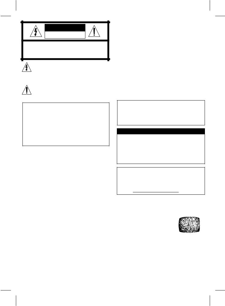
This lightning flash with arrowhead symbol within an equilateral triangle is intended to alert the user to the presence of uninsulated dangerous voltage within the product’s enclosure that may be of sufficient magnitude to constitute a risk of electric shock to persons.
The exclamation point within an equilateral triangle is intended to alert the user to the presence of important operating and maintenance (servicing) instructions in the literature accompanying the product.
WARNING :
TO REDUCE THE RISK OF FIRE OR ELECTRIC SHOCK, DO NOT EXPOSE THIS PRODUCT TO RAIN OR MOISTURE.
CAUTION : TO PREVENT ELECTRIC SHOCK, DO NOT USE THIS PLUG WITH AN EXTENSION CORD, RECEPTACLE OR OTHER OUTLET UNLESS THE PLUG CAN BE FULLY INSERTED WITHOUT EXPOSING ANY PARTS OF THE BLADES.
IMPORTANT COPYRIGHT INFORMATION : Many television programs and films are copyrighted. In certain circumstances, copyright law may apply to private in-home video taping of copyrighted materials.
FCC WARNING: This equipment may generate or use radio frequency energy. Changes or modifications to this
equipment may cause harmful interference unless the modifications are expressly approved in the instruction manual. The user could lose the authority to operate this equipment if an unauthorized change or modification is made.
REGULATORY INFORMATION: FCC Part 15
This product has been tested and found to comply with the limits for a Class B digital device, pursuant to Part 15 of the FCC Rules. These limits are designed to provide reasonable protection against harmful interference when the product is operated in a residential installation. This product generates, uses, and can radiate radio frequency energy and, if not installed and used in accordance with the instruction manual, may cause harmful interference to radio communications. However, there is no guarantee that interference will not occur in a particular installation. If this product does cause harmful interference to radio or television reception, which can be determined by turning the product off and on, the user is encouraged to try to correct the interference by one or more of the following measures:
Reorient or relocate the receiving antenna. Increase the separation between the product and receiver.
Connect the product into an outlet on a circuit different from that to which the receiver is connected.
Consult the dealer or an experienced radio/TV technician for help.
Note to CATV system installer (USA only): This reminder is provided to call the CATV system installer’s attention to Section 820-40 of the NEC which provides guidelines for proper grounding and, in particular, specifies that the cable ground shall be connected to the grounding system of the building, as close to the point of cable entry as practical.
MOISTURE CONDENSATION
If you pour a cold liquid into a glass, water vapor in the air will condense on the surface of the glass. This is moisture condensation. Moisture condensation on the head drum, one of the most crucial parts of the unit, will cause damage to the tape. When the VCR is exposed to a rapid temperature change from cold to warm, some condensation will occur. Under this condition, connect the power cord to the AC line, press POWER on and allow at least two hours for the VCR to dry out.
The serial number is found on the back of this unit. This number is unique to this unit and not available to others. You should record requested information here and retain this guide as a permanent record of your purchase.
Model No. |
VWM-900 |
Serial No.
Video Head Cleaning
Video head clogging
The video heads are the means by which the unit reads the picture from the tape during playback. In the unlikely event that the heads become dirty enough to be clogged, no picture will be played back. This can easily be determined if, during playback of a known good tape, there is good sound, but no picture (picture is extremely snowy). If this is the case, use a high quality head cleaning system or have them cleaned professionally.
Snowy Picture
Video head cleaning
Video head cleaning is needed when the playback picture becomes unclear. This signifies that the heads are getting dirty and can occur when playing poor quality or damaged tapes. If the heads require cleaning, use an equivalent high quality chemical non-abrasive (wet) head cleaning tape or have them cleaned professionally. If playing a head cleaning tape in the unit once does not improve the picture, play it several times before requesting service.
Notes
DO NOT ATTEMPT TO CLEAN THE VIDEO HEADS OR SERVICE THE UNIT BY REMOVING THE TOP COVER. Video heads may eventually wear out and should be replaced when they fail to produce clear pictures.
To help prevent video head clogging, use only good quality VHS tapes. Discard worn out tapes.
2
IMPORTANT SAFETY INSTRUCTIONS
CAUTION: PLEASE READ AND OBSERVE ALL WARNINGS AND INSTRUCTIONS IN THIS OWNER’S MANUAL. AND THOSE MARKED ON THE PRODUCT. RETAIN THIS BOOKLET FOR FUTURE REFERENCE.
This product has been designed and manufactured to assure personal safety. Improper use can result in electric shock or fire hazard. The safeguards incorporated in this product will protect you if you observe the following procedures for installation, use, and servicing.
This product does not contain any parts that can be repaired by the user.
DO NOT REMOVE THE CABINET COVER, OR YOU MAY BE EXPOSED TO DANGEROUS VOLTAGE. REFER SERVICING TO QUALIFIED SERVICE PERSONNEL ONLY.
1.Read these instructions. - All these safety and operating instructions should be read before the product is operated.
2.Keep these instructions. - The safety, operating and use instructions should be retained for future reference.
3.Heed all warnings. - All warnings on the product and in the operating instructions should be adhered to.
4.Follow all instructions. - All operating and use instructions should be followed.
5.Do not use this apparatus near water. – For example: near a bath tub, wash bowl, kitchen sink, laundry tub, in a wet basement; or near a swimming pool; and like.
6.Clean only with dry cloth. – Unplug this product from the wall outlet before cleaning. Do not use liquid cleaners.
7.Do not block any ventilation openings. Install in accordance with the manufacturer’s instructions. - Slots and openings in the cabinet are provided for ventilation and to ensure reliable operation of the product and to protect it from over heating. The openings should never be blocked by placing the product on a bed, sofa, rug or other similar surface. This product should not be placed in a built-in installation such as a bookcase or rack unless proper ventilation is provided or the manufacturer’s instructions have been adhered to.
8.Do not install near any heat sources such as radiators, heat registers, stoves, or other apparatus (including amplifiers) that produce heat.
9.Do not defeat the safety purpose of the polarized or grounding-type plug. A polarized plug has two
blades with one wider than the other. A grounding type plug has two blades and a third grounding prong. The wide blade or the third prong are provided for your safety. If the provided plug does not fit into your outlet, consult an electrician for replacement of the obsolete outlet.
10.Protect the power cord from being walked on or pinched particularly at plugs, convenience receptacles, and the point where they exit from the apparatus.
11.Only use attachments/accessories specified by the manufacturer.
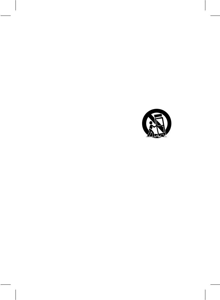
12.Use only with the cart, stand, tripod, bracket, or table specified by the manufacturer, or sold with apparatus. When a cart is used, use caution when moving the cart/apparatus combination to avoid injury from tip-over.
13.Unplug this apparatus during lightning storms or when unused for long periods of time.
14.Refer all servicing to qualified service personnel. Servicing is required when the apparatus has been damaged in any way, such as power-supply cord or plug is damaged, liquid has been spilled or objects have fallen into the apparatus, the apparatus has been exposed to rain or moisture, does not operate normally, or has been dropped.
3

CONTROL NAMES AND
LOCATIONS
FRONT
POWER STOP/ |
CASSETTE |
REW PLAY FF |
EJECT |
COMPARTMENT |
|
|
|
|
|
|
|
|
|
|
|
|
|
|
|
|
|
|
|
|
|
|
|
|
|
|
|
|
|
|
|
|
|
|
|
|
|
|
|
|
|
|
|
|
|
|
|
|
|
|
|
|
|
|
|
|
|
|
|
|
|
|
|
|
|
|
|
|
|
|
|
|
|
|
|
|
|
|
|
|
|
|
|
|
|
|
|
|
|
|
|
|
|
|
|
|
|
|
|
|
|
|
|
|
|
|
|
|
|
|
VIDEO IN/ |
CHANNEL |
|
|
Remote |
REC |
PAUSE/ |
||||||||||
AUDIO IN (L/R) |
|
|
(V/v) |
|
|
|
Sensor |
|
|
STILL |
|||||||
|
JACKS |
|
|
|
|
|
|
|
|
|
|
|
|
|
|
|
|
|
|
|
|
|
INDICATOR PANEL |
|
|
|
|
||||||||
POWER indicator |
|
|
TAPE IN indicator |
TIMER indicator |
|||||||||||||
|
|
|
|
|
|
|
|
|
|
|
|
|
|
|
|
|
|
|
|
|
|
|
|
|
|
|
|
|
|
|
|
|
|
|
|
|
|
|
|
|
|
|
|
|
|
|
|
|
|
|
|
|
|
VCR indicator |
REC (Record) |
Use TV/VCR on the remote control to turn this |
indicator |
indicator ON or OFF. |
|
ON: for playback, VCR programming, or |
|
watching TV programs through the VCR tuner. |
|
OFF: for watching TV programs through the |
|
TV tuner. |
|
REAR
Power Cord |
VIDEO IN/ |
VIDEO OUT/ |
|
|
ANT.IN |
|
AUDIO IN (L/R) |
AUDIO OUT (L/R) |
|
||
|
JACKS |
JACKS |
|
|
|
|
|
|
|
AUDIO |
|
|
|
|
|
|
R |
|
|
|
|
|
ANT.IN |
|
|
LINE1(AUX1) |
IN |
OUT |
|
|
|
|
|
VHF/UHF |
|
|
|
|
|
|
L |
|
|
|
IN |
OUT |
/CATV |
|
|
|
|
VIDEO |
RF OUT |
RF OUT (VHF/UHF/CATV)
REMOTE CONTROL 
POWER |
EJECT |
|
Number buttons |
TV/VCR |
|
SLOW |
Ad JUMP |
|
PLAY |
INPUT |
|
REW |
SP/SLP |
|
CLEAR |
PAUSE |
|
REC |
FF |
|
D E F G arrows |
STOP |
|
TV CONTROL |
MENU |
|
buttons |
ENTER |
|
TV POWER, TV |
||
(CLK/COUNT) |
||
INPUT, TV CH + |
||
|
||
and TV CH – , |
CH(channel)/ |
|
VOL + and VOL –. |
TRACK(tracking) |
REMOTE CONTROL OPERATIONS
Aim the remote control unit at the sensor on the front panel of the VCR.
For TV operation:
This remote control will only work with Sanyo TVs.
HOW TO INSTALL THE BATTERIES 1
2
3
NOTES
•The remote control will not operate properly if an obstuction is between the VCR and the remote control.
•If the functional range is short, try new batteries.
•Batteries installed backwards may leak and damage your Remote Control.
•Do not mix old and new batteries or carbon types with alkaline types.
•Remove the batteries from the battery compartment if the remote control will not be used for a long time.
IMPORTANT NOTE:
SPENT OR DISCHARGED BATTERIES MUST BE RECYCLED OR DISPOSED OF IN A SAFE MANNER IN COMPLIANCE WITH ALL APPLICABLE LAWS. FOR DETAILED INFORMATION, CONTACT YOUR LOCAL COUNTY SOLID WASTE AUTHORITY.
4

INSTALLATION
Placing your VCR on top of or under the TV receiver may result in interference on the TV screen when the VCR is on. If this occurs, move the VCR to a position beside the TV receiver.
VCR TO TV CONNECTION
R-AUDIO-L VIDEO
 OUT
OUT OUT
OUT
IN |
IN |
Cable/ |
|
|
Antenna |
|
|
AUDIO |
|
|
|
|
R |
|
|
|
ANT.IN |
LINE1(AUX1) |
IN |
OUT |
|
|
|
L |
|
|
IN |
OUT |
VHF/UHF |
|
/CATV |
||
|
|
|
|
|
|
VIDEO |
RF OUT |
ANTENNA TO VCR CONNECTIONS
1 Disconnect the antenna leads from the rear of the TV receiver.
2 Identify the type of cable from your antenna. If it is a round cable as illustrated, it is a 75 ohm coaxial antenna cable. This cable will connect directly to the connector marked ANT.IN on your VCR.
If your antenna lead wire is a flat type antenna cable, connect it to a Antenna Adaptor (300-ohm to 75-ohm) (not supplied) and slip the Adaptor onto the ANT.IN connector. The Adaptor does not screw on to the VCR, it just slips over the connector.
IN OUT
|
|
AUDIO |
|
|
|
|
R |
|
|
|
ANT.IN |
LINE1(AUX1) |
IN |
OUT |
|
|
|
L |
|
|
|
|
|
|
IN |
OUT |
VHF/UHF |
|
/CATV |
||
|
|
|
|
|
|
VIDEO |
RF OUT |
|
|
|
When using the RF coaxial cable (Supplied)
Connect the 75-ohm Coaxial Cable to RF OUT (VHF/UHF/CATV) on the VCR. Connect the other end to the 75ohm antenna input on the back of the TV.
When using the Audio/Video cable (Not supplied)
If your TV has A/V input jacks, you can connect your VCR’s AUDIO/VIDEO jacks to the back of your TV.
Direct audio/video connections usually result in better picture and sound quality for tape playback. Please see your TV’s owner’s manual for details on how to set your TV to the VIDEO mode using the TV/VIDEO button on your TV.
VCR Output Channel Setting
1.Set the TV to the VCR channel (3 or 4).
2.While the VCR is turned off, press and hold CHANNEL (V/v) on the front panel for more than five seconds. Indicators on the INDICATOR PANEL blinks as follows:
(CH 03)
(CH 04)
3.Use CHANNEL (V/v) on the front panel to change the RF output channel (CH 03 or CH 04).
4.Turn the VCR off and then on again.
Without Cable Box
If your cable wire is connected to your TV without a converter or descrambler box, unscrew the wire from your TV and attach it to the ANT.IN connector on the VCR. Use the supplied round coaxial cable to connect the VCR’s RF OUT (VHF/UHF/CATV) connector and the 75 ohm antenna input connector on the TV. With this connection, you can receive all midband, super band, and hyperband channels.
With Cable Box
If a converter is required in your cable system, follow the instruction below.
The cable hookup permits both TV and VCR operation.
To view or record a CATV channel
1Set the TV to the VCR channel (3 or 4).
2Set the VCR channel selector to the output channel of the Cable Converter box by pressing the CH/TRACK (v/V) or the number buttons (0-9) of your VCR. (Example: CH3).
3Select the channel to view on the Cable Converter Box.
NOTES
•With this connection, you CANNOT record one program while viewing another.
•Channel memory programming is not needed when using this connection.
5
 Loading...