


Overview
The LC72336 and LC72338 are single-chip
microcontrollers for use in electronic tuners. These
products include on chip a PLL circuit that can operate at
up to 150 MHz and 1/3 duty LCD drivers. They feature a
highly efficient instruction set and powerful hardware.
Functions
• High-speed programmable divider
• Program memory (ROM)
— LC72336: 6143 × 16 bits (12 kB)
— LC72338: 8191 × 16 bits (16 kB)
• Data memory (RAM): 512 × 4 bits
• All instructions are one-word instructions
• Cycle time: 1.33 µs
• Stack: 8 levels
• LCD drivers: Up to 96 segments (1/3 duty, 1/3 bias)
• Serial I/O: Up to 3 channels (8-bit 3-wire type)
• External interrupts: 2 interrupts (INT0, INT1)
Interrupt on rising or falling edge (selectable)
• Internal interrupts: 3 interrupt
Two built-in timer interrupts and 1 serial I/O interrupt
• Nested interrupt levels: 4 levels
• D/A converter: 4 channels (8-bit PWM output)
• A/D converter: 4 channels
(6-bit successive approximation)
• General-purpose ports:
— Input ports: 8
— Output ports: 12 (16 maximum)
— I/O ports: 8 (20 maximum, can be switched between
input and output in bit units.)
• PLL block: Supports 4 types of dead zone control, and
includes a built-in unlock detection circuit.
Supports 12 different reference frequencies.
• Universal counter: 20 bits (Can be used for either
frequency or period measurement.)
• Timers: Eight types of time measurement
• Beep function: Six beep tones
• Reset: Built-in voltage detection type reset circuit
• Halt mode: Stops the controller operating clock.
• Operating supply voltage: 4.5 to 5.5 V (3.5 to 5.5 V if
only the controller block operates.)
Package Dimensions
unit: mm
3174-QFP80E
CMOS LSI
Ordering number : EN5157C
O3097HA (OT)/13095HA (OT) No. 5157-1/16
SANYO: QIP80E
[LC72336, 72338]
SANYO Electric Co.,Ltd. Semiconductor Bussiness Headquarters
TOKYO OFFICE Tokyo Bldg., 1-10, 1 Chome, Ueno, Taito-ku, TOKYO, 110 JAPAN
Single-Chip Microcontrollers
with Built-In LCD Driver and PLL Circuits
LC72336, 72338
This LSI can easily use CCB that is SANYO’s original bus format.
• CCB is a trademark of SANYO ELECTRIC CO., LTD.
• CCB is SANYO’s original bus format and all the bus
addresses are controlled by SANYO.
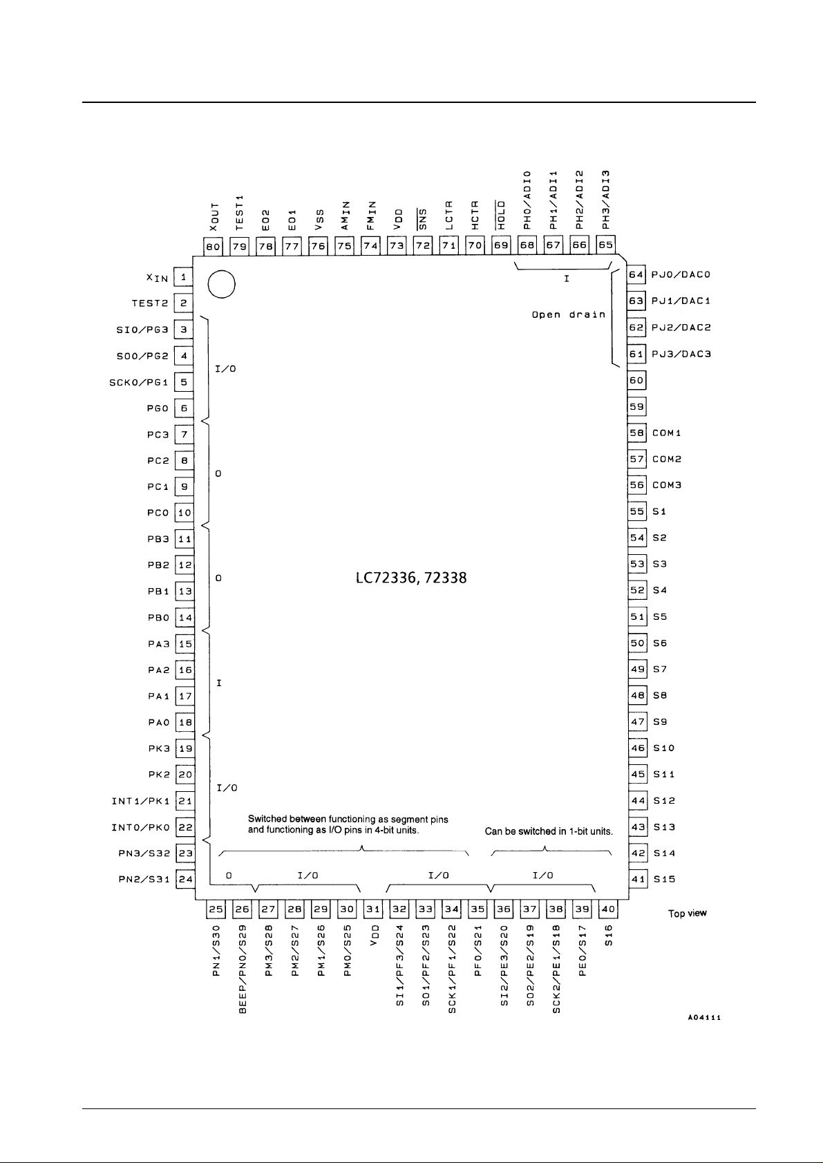
Pin Assignment
No. 5157-2/16
LC72336, 72338
V
dd1
V
dd2
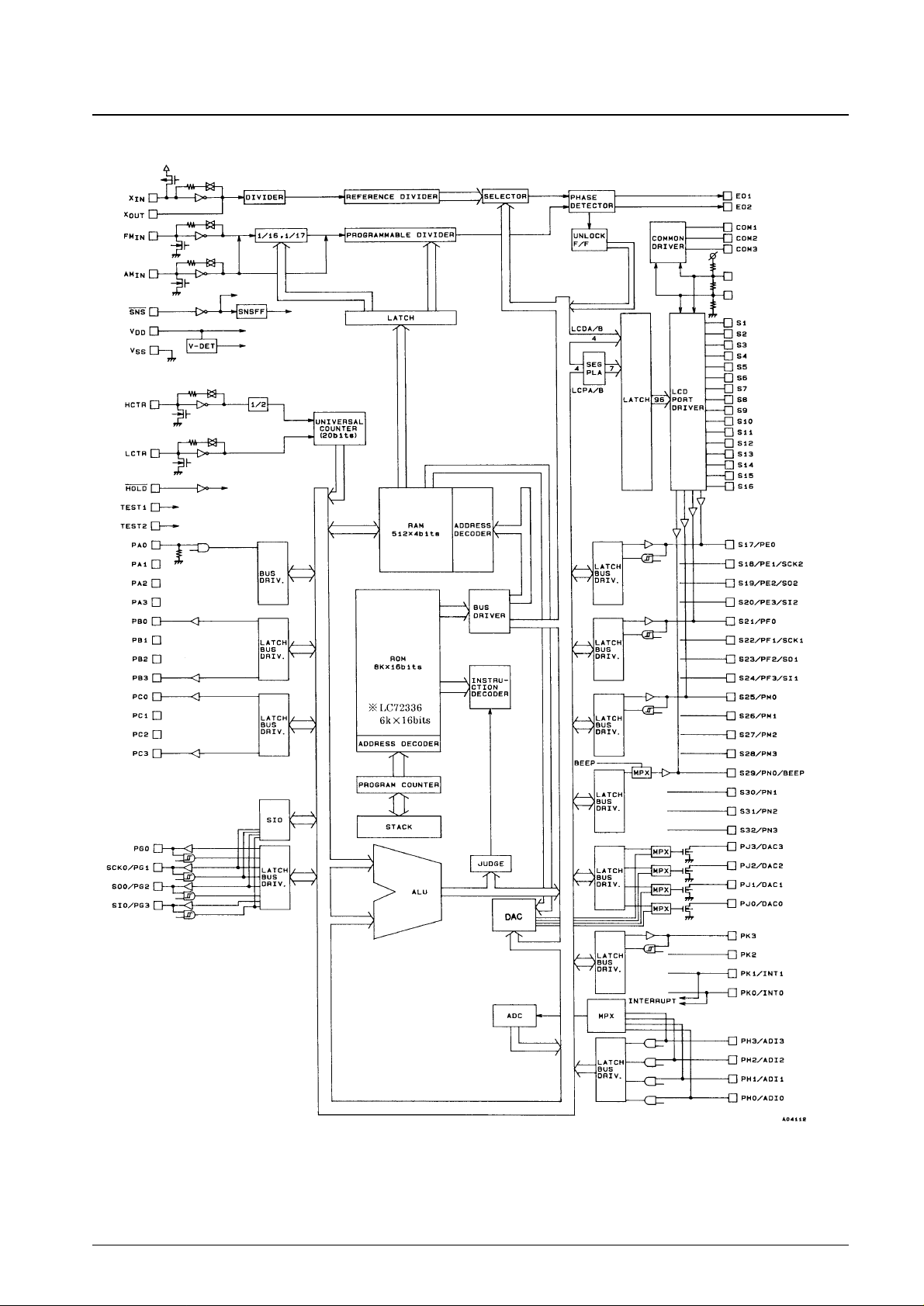
Block Diagram
No. 5157-3/16
LC72336, 72338
V
dd1
V
dd2
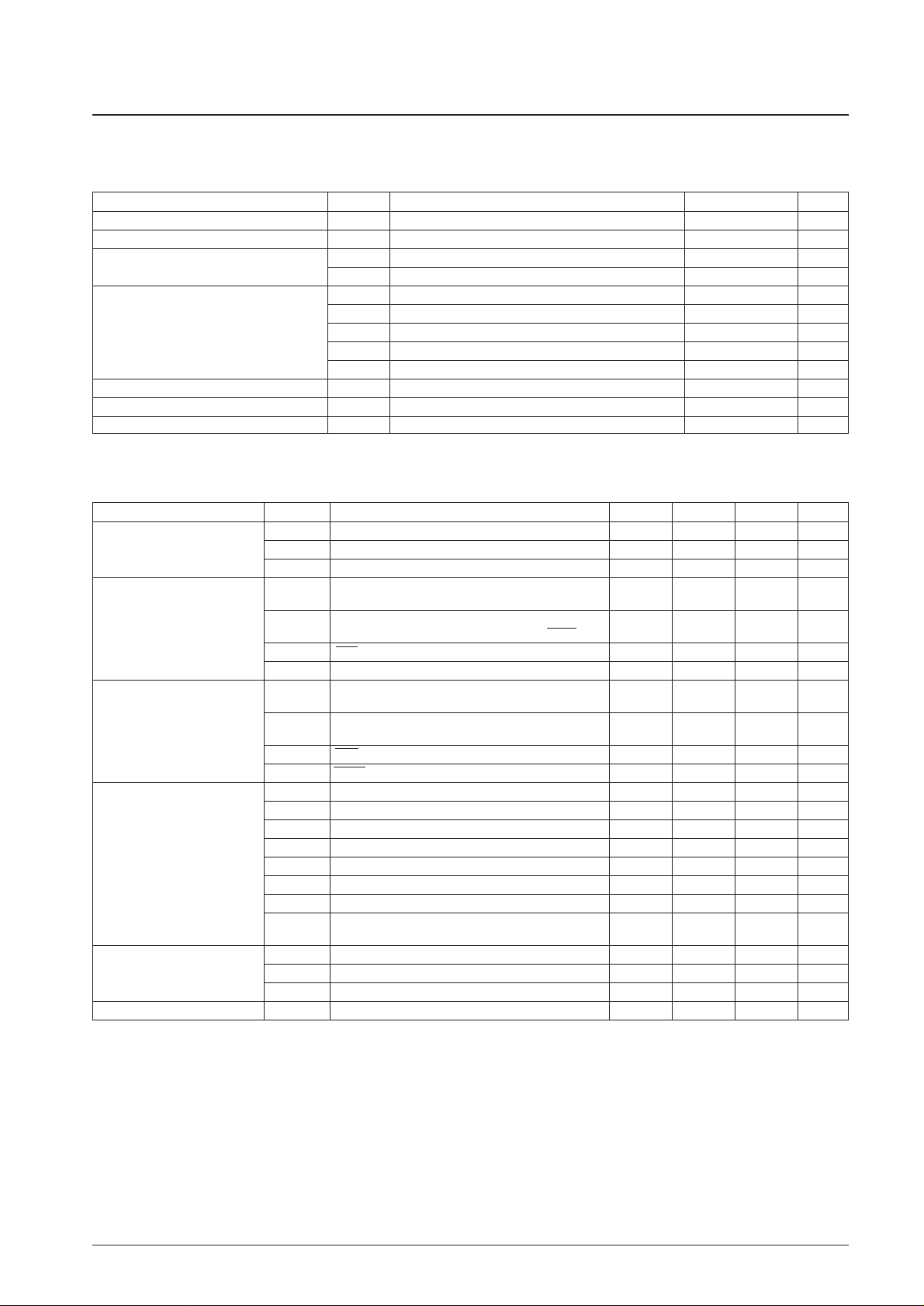
Specifications
Absolute Maximum Ratings at Ta = 25°C, VSS= 0 V
Note: * Reference value
Allowable Operating Ranges at Ta = –40 to +85°C, VDD= 3.5 to 5.5 V
No. 5157-4/16
LC72336, 72338
Parameter Symbol Conditions Ratings Unit
Maximum supply voltage V
DD
max –0.3 to +6.5 V
Input voltage V
IN
All input pins –0.3 to VDD+ 0.3 V
Output voltage
V
OUT
(1) Port PJ –0.3 to +15 V
V
OUT
(2) All output ports other than V
OUT
(1) –0.3 to VDD+ 0.3 V
I
OUT
(1) Port PJ 0 to +5 mA
I
OUT
(2) PE, PF, PG, PK, PM, PN, EO1, EO2 0 to +3 mA
Output current I
OUT
(3) Ports PB and PC 0 to +1 mA
I
OUT
(4) S1 to S32 300 µA
I
OUT
(5) COM1 to COM3 3 mA
Allowable power dissipation Pd max Ta = –45 to 85°C 300 mW*
Operating temperature Topr –40 to +85 °C
Storage temperature Tstg –45 to +125 °C
Parameter Symbol Conditions min typ max Unit
V
DD
(1) CPU and PLL operating 4.5 5.0 5.5 V
Supply voltage V
DD
(2) CPU operating 3.5 5.5 V
V
DD
(3) Memory retention 1.3 5.5 V
V
IH
(1)
Ports PE, PH, and PM,
0.7 V
DD
V
DD
V
HCTR and LCTR (when selected for input)
Input high-level voltage
V
IH
(2)
Ports PF, PG, and PK,
0.8 V
DD
V
DD
V
LCTR (frequency measurement mode), and HOLD
V
IH
(3) SNS 2.5 V
DD
V
V
IH
(4) Port PA 0.6 V
DD
V
DD
V
V
IL
(1)
Port PE, PH, and PM,
0 0.3 V
DD
V
HCTR and LCTR (when selected for input)
Input low-level voltage
V
IL
(2)
Port PA, PF, PG, and PK,
0 0.2 V
DD
V
LCTR (frequency measurement mode)
V
IL
(3) SNS 0 +1.3 V
V
IL
(4) HOLD 0 0.4 V
DD
V
f
IN
(1) XIN 4.0 4.5 5.0 MHz
f
IN
(2) FMIN: VIN(2), VDD(1) 10 150 MHz
f
IN
(3) FMIN: VIN(3), VDD(1) 10 130 MHz
f
IN
(4) AMIN (H): VIN(3), VDD(1) 2.0 40 MHz
Input frequency
f
IN
(5) AMIN (L): VIN(3), VDD(1) 0.5 10 MHz
f
IN
(6) HCTR: VIN(3), VDD(1) 0.4 12 MHz
f
IN
(7) LCTR: VIN(3), VDD(1) 100 500 kHz
f
IN
(8)
LCTR (frequency measurement mode):
1 20 × 10
3
Hz
V
IH
(2), VIL(2), VDD(1)
V
IN
(1) XIN 0.5 1.5 Vrms
Input amplitude V
IN
(2) FMIN 0.10 1.5 Vrms
V
IN
(3) FMIN, AMIN, HCTR, LCTR 0.07 1.5 Vrms
Input voltage range V
IN
(4) ADI0 to ADI3 0 V
DD
V
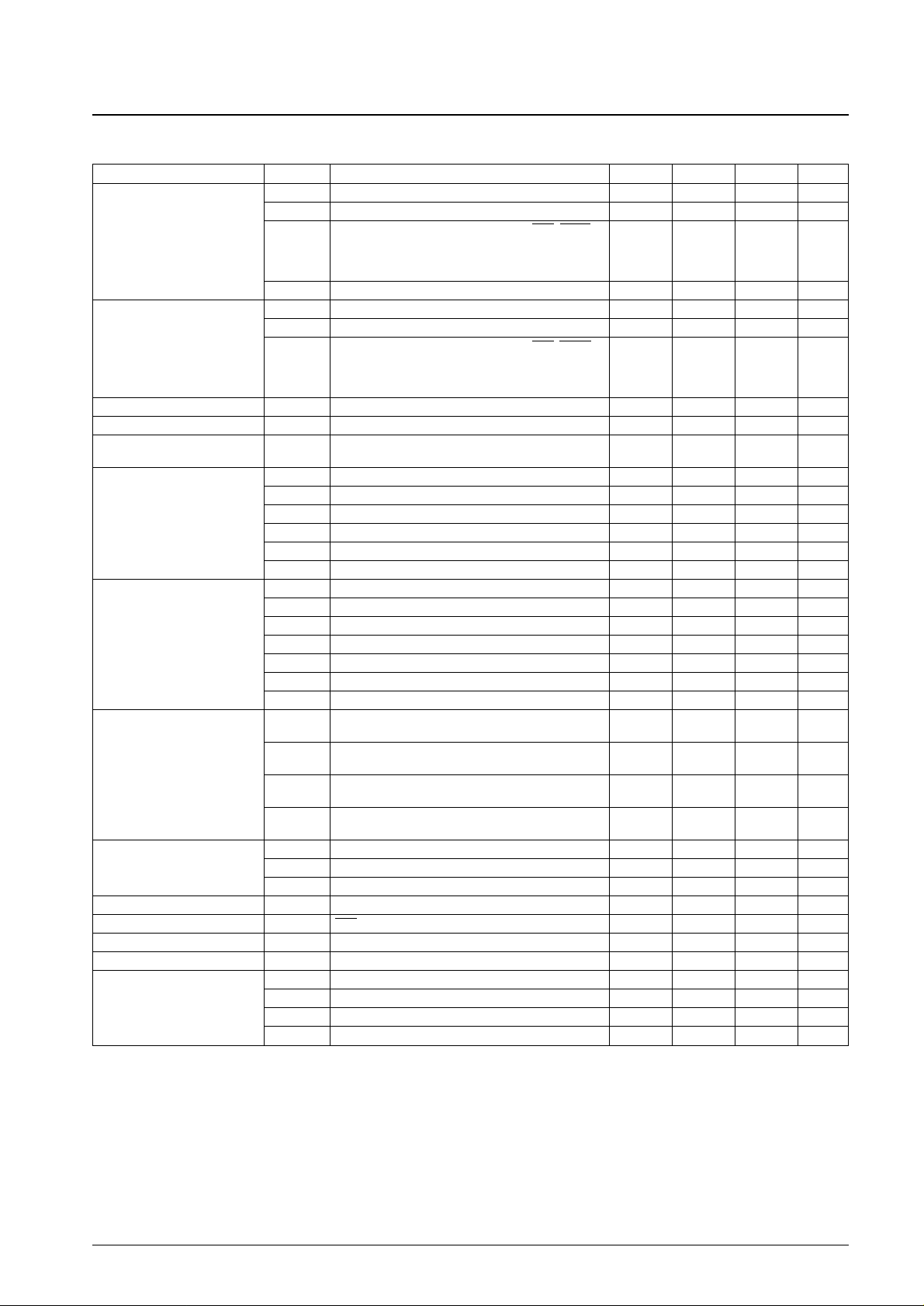
Electrical Characteristics for the Allowable Operating Ranges
Note: * In case of instruction execution for 20 steps at intervals of 1 ms, with the PLL, counter functions and other functions all stopped.
No. 5157-5/16
LC72336, 72338
Parameter Symbol Conditions min typ max Unit
I
IH
(1) XIN: VI= VDD= 5.0 V 2.0 5.0 15 µA
I
IH
(2) FMIN, AMIN, HCTR, LCTR: VI= VDD= 5.0 V 4.0 10 30 µA
Ports PA, PE, PF, PG, PH, PK, and PM, SNS, HOLD,
Input high-level current
I
IH
(3)
HCTR, LCTR: No pull-down resistors on port PA,
3.0 µA
V
I
= VDD= 5.0 V, with input mode selected
for ports PE, PF, PG, PK, and PM
IIH(4) With pull-down resistors on port PA, VI= VDD= 5.0 V 50 µA
I
IL
(1) XIN: VI= V
SS
2.0 5.0 15 µA
I
IL
(2) FMIN, AMIN, HCTR, LCTR: VI= V
SS
4.0 10 30 µA
Input low-level current
Ports PA, PE, PF, PG, PH, PK, and PM, SNS, HOLD,
I
IL
(3)
HCTR, LCTR: No pull-down resistors on port PA,
3.0 µA
V
I
= VSS, with input mode selected
for ports PE, PF, PG, PK, and PM
Input floating voltage V
IF
With pull-down resistors on port PA 0.05 V
DD
V
Pull-down resistance R
PD
(1) With pull-down resistors on port PA, VDD= 5 V 75 100 200 kΩ
Hysteresis V
H
Ports PF, PG, and PK, LCTR
0.1 V
DD
0.2 V
DD
V
(in frequency measurement mode)
V
OH
(1) Ports PB and PC: IO= –1 mA VDD– 2.0 V
V
OH
(2) Ports PE, PF, PG, PK, PM, and PN: IO= –1 mA VDD– 1.0 V
Output high-level voltage
V
OH
(3) EO1, EO2: IO= –500 µA VDD– 1.0 V
V
OH
(4) XOUT: IO= –200 µA VDD– 1.0 V
V
OH
(5) S1 to S32: IO= –20 µA VDD– 1.0 V
V
OH
(6) COM1, COM2, COM3: IO= –100 µA VDD– 1.0 V
V
OL
(1) Ports PB and PC: IO= 50 µA 2.0 V
V
OL
(2) Ports PE, PF, PG, PK, PM, and PN: IO= 1 mA 1.0 V
V
OL
(3) EO1, EO2: IO= 500 µA 1.0 V
Output low-level voltage V
OL
(4) XOUT: IO= 200 µA 1.0 V
V
OL
(5) S1 to S32: IO= 20 µA 1.0 V
V
OL
(6) COM1, COM2, COM3: IO= 100 µA 1.0 V
V
OL
(7) Port PJ: IO= 5 mA 0.75 2.0 V
V
MID
(1) S1 to S32: IO= ±20 µA
2/3 V
DD
±
V
1.0
V
MID
(2) S1 to S32: IO= ±20 µA
1/3 V
DD
±
V
Output mid-level voltage
1.0
V
MID
(3) COM1, COM2, COM3: IO= ±100 µA
2/3 V
DD
±
V
1.0
V
MID
(4) COM1, COM2, COM3: IO= ±100 µA
1/3 V
DD
±
V
1.0
I
OFF
(1) Ports PE, PF, PG, PK, PM, and PN –3.0 +3.0 µA
Output off leakage current I
OFF
(2) EO1 , EO2 –100 +100 nA
I
OFF
(3) Port PJ –5.0 +5.0 µA
AD conversion error — ADI0 to ADI3: V
DD
(1) –1/2 +1/2 LSB
Reject pulse width P
REJ
SNS 50 µs
Power-down detection voltage V
DET
2.7 3.0 3.3 V
Pull-down resistance R
PD
(2) TEST1, TEST2 10 kΩ
I
DD
(1) VDD(1): fIN(2) = 130 MHz, Ta = 25°C 12 mA
Current drain
I
DD
(2) VDD(2): halt mode*, Ta = 25°C (Fig. 1) 0.45 mA
I
DD
(3) VDD= 5.5 V, oscillator stopped, Ta = 25°C (Fig. 2) 5 µA
I
DD
(4) VDD= 2.5 V, oscillator stopped, Ta = 25°C (Fig. 2) 1 µA
 Loading...