

Sanyo DSR-M800P Instruction Manual
00e_cover_dsr_m800_6.fm Page 0 Tuesday, February 4, 2003 4:14 PM
Digital Video Recorder
|
|
|
|
|
|
|
|
|
Instruction manual |
|
|
|
English |
GB |
|
|
|
|
|
|
|
|
|
|
|
|
|
|
|
|
|
|
Bedinugsanleitung |
|
|
|
Deutsch |
D |
|
|
|
||||||
|
|
|
|
|
|
|
|
|
|
|
|
|
|
|
|
|
Manuel D'instructions |
|
|
|
|
|
F |
|
|
|
|
|
|
|
|
|
|
|
|
|
|
|
|
|
Manuel de Instrucciones |
|
|
|
|
|
E |
|
|
|
|
|
|
|
|
|
|
|
|
|
|
|
|
|
Manuale di Istruzioni |
|
|
|
Italiano |
I |
|
|
|
||||||
|
|
|
|
|
|
|
|
|
|
|
|
|
|
|
|
|
|
|
|
|
|
|
|
|
|
|
|
|
|
|
|
About this manual
Before installing and using this unit, please read this manual carefully. Be sure to keep it handy for later reference.
Über diese Anleitung
Lesen Sie bitte diese Bedienungsanleitung vor der Installation und der Verwendung des Gerätes sorgfältig durch. Bewahren Sie die Anleitung zum späteren Nachschlagen auf.
À propos de ce manuel
Avant d’installer et d’utiliser cet appareil, veuillez lire ce manuel attentivement. Assurez-vous de le garder à portée de la main pour référence ultérieure.
Acerca de este manual
Antes de instalar y usar este aparato, lea detenidamente este manual. Asegúrese de guardarlo a mano para futuras referencias.
Nota su questo manuale
Leggere attentamente questo manuale prima di passare all’installazione ed all’uso di questo apparecchio. Conservare il manuale in un posto sicuro per riferimenti futuri.
POWER |
|
|
|
|
|
ALARM |
|
SEARCH |
|
|
|
|
PLAY/ |
|
MENU |
REVIEW |
CUE |
EXIT/OSD |
STOP |
|
TIMER |
|
REC/STOP |
||||
|
|
|
|
|
||
|
|
|
|
|
|
STILL |
|
MENU RESET |
|
|
|
|
|
FULL |
|
|
|
|
|
LOCK/REMOTE |
|
|
|
|
|
|
USB |
LAN |
|
|
|
|
|
|
(LINK/ACT.) |
|
|
|
|
|
|
e_dsr_m800.book Page 1 Monday, February 3, 2003 10:51 AM
PRECAUTION
WARNING: TO REDUCE THE RISK OF FIRE OR ELECTRIC SHOCK, DO NOT EXPOSE THIS APPLIANCE TO RAIN OR OTHER MOISTURE. To avoid electrical shock, do not open the cabinet. Refer servicing to qualified personnel only.
If the power supply cord (AC power cord) of this appliance is damaged, it must be replaced. Return to a SANYO Authorised Service Centre for replacement of the cord.
Location
For safe operation and satisfactory performance of your unit, keep the following in mind when selecting a place for its installation:
Shield it from direct sunlight and keep it away from sources of intense heat.
Avoid dusty or humid places.
Avoid places with insufficient ventilation for proper heat dissipation. Do not block the ventilation holes at the top and bottom of the unit. Do not place the unit on a carpet because this will block the ventilation holes.
Install the unit in a horizontal position only. Avoid locations subject to strong vibrations.
Avoid moving the unit between cold and hot locations. Do not place the unit directly on top of a monitor TV, as this may cause playback or recording problems.
Avoiding Electrical Shock and Fire
Do not handle the power cord with wet hands.
Do not pull on the power cord when disconnecting it from an AC wall outlet. Grasp it by the plug.
If any liquid is spilled on the unit, unplug the power cord immediately and have the unit inspected at a factoryauthorised service centre.
Do not place anything directly on top of this unit.
SERVICE
This unit is a precision instruments and if treated with care, will provide years of satisfactory performance. However, in the event of a problem, the owner is advised not to attempt to make repairs or open the cabinet. Servicing should always be referred to your dealer or Sanyo Authorized Service Centre.
CAUTION
Danger of explosion if battery is incorrectly replaced. Replace only with the same or equivalent type recommended by the manufacturer.
Discard used batteries according to the manufacture’s instructions.
1
00e_02_dsr_m800_6.fm Page 2 Thursday, February 6, 2003 12:05 PM
INTRODUCTION
Main features
This digital video recorder can be used to store images recorded by a monitoring camera onto its built-in hard disk.
Comes with a large-capacity (120 GB or 240 GB) hard disk.
For the 120 GB model, a hard disk upgrade is available (sold separately) that gives you a total of 240 GB of memory.
Complete range of recording/playback functions
z You can play back and record images at the same time.
z You can record and play back audio.
z The timer record function lets you make recordings at different times each day. (JP.29)
The search function lets you instantly display the desired image. (JP.18)
z Searching in order of alarm occurrence z Searching by date/time
The security lock function lets you restrict users, for data and equipment management. (JP.34)
Expandable, can be connected to a PC
z The Ethernet terminal lets you connect the digital video recorder to a network, for remote operation/ remote monitoring.*
z Network connection lets you control up to 1,000 DVRs (digital video recorders) using 4 PCs.*
z Can be connected to a system controller (sold separately) using the RS-485 terminal.
z A CompactFlash reader can be connected using the USB terminal, letting you upload/download menu data.
Items marked by asterisks (*) require the VA-SW800 remote operation software (sold separately). For more information, contact a Sanyo service center.
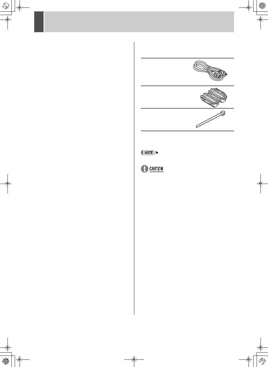
Accessories
Check that you have all the parts below.
Power cord
Ferrite core (3)
For: LAN connection cable
DVR power cord
TV monitor power cord
Power cord tie
Symbols used in this manual
Information describing operation methods or how to get the most out of functions
Information describing the correct use of the digital video recorder
(JP. xx) Indicates manual page to refer to.
Copyright
zThis manual and software are copyrighted by Sanyo Electric Co., Ltd.
zBrand and product names used in this manual are the trademarks or registered trademarks of their respective companies.
zExcept for personal use, copyright law prohibits the use of recorded copyrighted images without the permission of the copyright holder
zSanyo's DSR-M800P Digital Video Recorder uses software components distributed as freeware based on end user license agreements or copyright notifications (collectively referred to as “EULAs”) set forth by third parties.
2

e_dsr_m800toc.fm Page 3 Saturday, April 5, 2003 4:33 PM
CONTENTS
INTRODUCTION |
|
1 BEFORE USE................................................. |
5 |
Notes on handling internal hard disk drive |
|
components .................................................... |
5 |
Do not use the digital video recorder in the |
|
following locations:.......................................... |
5 |
The hard disk and cooling fan are |
|
consumables................................................... |
5 |
Installation conditions...................................... |
5 |
For important recordings................................. |
5 |
Hard disk protection ........................................ |
6 |
Care ................................................................ |
6 |
During extended disuse .................................. |
6 |
Backup battery ................................................ |
6 |
MENU button .................................................. |
6 |
2 NAMES AND FUNCTIONS OF PARTS ......... |
7 |
Front panel ...................................................... |
7 |
Rear panel....................................................... |
8 |
3 INSTALLATION AND CONNECTIONS ......... |
9 |
Basic connections ........................................... |
9 |
System controller connections ........................ |
9 |
Connecting a remote control circuit................. |
9 |
Connecting cables to the control and alarm |
|
terminals........................................................ |
10 |
Connecting to a network ............................... |
10 |
Connecting the power cord ........................... |
10 |
|
OPERATION |
|
1 |
SCREEN DISPLAY AND POSITION ........... |
11 |
|
Operation display area.................................. |
11 |
|
Changing the position of the operating |
|
|
display........................................................... |
11 |
2 |
SETTING THE LANGUAGE/CLOCK........... |
12 |
|
To change the language ............................... |
12 |
|
Setting the time ............................................. |
13 |
3 |
NORMAL RECORDING/TIMER |
|
|
RECORDING ................................................ |
14 |
|
Normal recording .......................................... |
14 |
|
Timer recording............................................. |
14 |
4 |
ALARM RECORDING .................................. |
15 |
|
Alarm recording............................................. |
15 |
5 |
NORMAL RECORDING/TIMER RECORDING |
|
|
PLAYBACK .................................................. |
16 |
|
Playback........................................................ |
16 |
|
Playback while fast-forwarding/rewinding ..... |
16 |
|
Viewing still images....................................... |
17 |
|
Frame advance (reverse).............................. |
17 |
6 |
SEARCHING FOR RECORDED IMAGES ... |
18 |
|
Alarm search ................................................. |
18 |
|
Date/time search ........................................... |
19 |
7 |
PREVENTING ACCIDENTAL OPERATION |
|
|
(KEY LOCK FUNCTION).............................. |
21 |
|
Setting the key lock function ......................... |
21 |
|
Releasing the key lock function..................... |
21 |
3
e_dsr_m800.book Page 4 Monday, February 3, 2003 10:51 AM
CONTENTS
|
SETTINGS |
|
|
MENU CONFIGURATION AND |
|
|
OPERATIONS .............................................. |
22 |
|
Displaying the menu screen and sub-menu |
|
|
screens ......................................................... |
22 |
|
To restore menu setting items to their |
|
|
initial values .................................................. |
22 |
|
Overview of sub-menus ................................ |
23 |
1 |
LANGUAGE/CLOCK SET............................ |
24 |
|
<SUMMER TIME> settings........................... |
24 |
|
<EXT.CLOCK SET> settings ........................ |
25 |
2 |
REC MODE SET........................................... |
27 |
|
<REC MODE SET> setting items ................. |
27 |
|
Settings ......................................................... |
28 |
|
Starting recording again when the FULL |
|
|
indicator lights ............................................... |
28 |
3 |
TIMER REC SET .......................................... |
29 |
|
Timer setting items........................................ |
29 |
|
Timer reservations every day at the same |
|
|
time with the same image quality.................. |
29 |
|
To cancel all timer reservations .................... |
30 |
|
Timer reservations spanning more than |
|
|
24 hours ........................................................ |
30 |
|
Setting holidays............................................. |
31 |
4 |
DISPLAY/BUZZER SET ............................... |
32 |
|
<DISPLAY/BUZZER SET> setting items ...... |
32 |
|
Settings ......................................................... |
33 |
5 |
SECURITY LOCK SET................................. |
34 |
|
Password setting example ............................ |
34 |
|
Password setting........................................... |
34 |
|
Setting passwords......................................... |
34 |
|
Setting the user password............................. |
35 |
|
Setting the authorization for recording and |
|
|
playback operations ...................................... |
36 |
|
Setting the security lock ................................ |
36 |
6 |
RS-485/NETWORK SET .............................. |
37 |
|
Network connections and settings ................ |
37 |
|
RS-485 connections and settings ................. |
38 |
7 |
POWER FAILURE/USED TIME ................... |
39 |
8 |
MENU UPLOAD/DOWNLOAD..................... |
40 |
|
Settings ......................................................... |
40 |
9 |
INITIALIZE/ADD HDD .................................. |
42 |
|
Initializing the hard disk................................. |
42 |
|
Adding a hard disk (120 GB model only) ...... |
43 |
OTHER
1 INTERFACE SPECIFICATIONS |
44 |
|
2 SPECIFICATIONS |
46 |
|
||||
RS-485 specifications ................................... |
44 |
|
Dimensions ................................................... |
47 |
RS-485 termination switch settings............... |
44 |
|
|
|
DVR/VCR command table ............................ |
45 |
|
|
|
|
|
|
|
|
OPERATION INTRODUCTION
SETTINGS
OTHER
4

e_dsr_m800.book Page 5 Monday, February 3, 2003 10:51 AM
1 |
BEFORE USE |
Notes on handling internal hard disk drive components
This unit has a built-in hard disk drive (HDD).
Be sure to observe the following points carefully when operating, setting-up and servicing the unit.
Do not subject the unit to shocks or vibration.
If the unit is subjected to shocks or vibration, it may damage the HDD or cause corruption of the data stored in the HDD. z Do not move the unit while the power is turned on.
Always be sure to turn off the power before removing the unit from or placing it onto the rack.
z When transporting the unit, pack it securely using the specified packing materials. In addition, use a method of transportation that minimizes vibration.
z When placing the unit down on a surface such as a floor, attach the specified feet to the base of the unit and place it down gently. If the feet are not attached, place the unit down very carefully so that it does not make any noise.
Do not move the unit for 30 seconds after turning off the power.
After the power is turned off, the disk inside the HDD will continue to spin for a brief period due to inertia, and the heads will be in an unstable state.
During this time, the unit is even more susceptible to shocks and vibration than when power is being supplied. Make sure that the unit is not subjected to even gentle vibration for at least 30 seconds after turning off the power.
Do not operate the unit when condensation has formed.
If the unit is operated when condensation has formed, it may cause operating problems.
If sudden changes in the ambient temperature occur, wait for the temperature to stablize before operating the unit.
Notes when replacing the HDD
Be sure to follow the correct replacement procedure when replacing the HDD.
zHDDs that have been removed from their packing may not operate correctly if they are subjected to any shocks and vibration. It is recommended that you place HDD onto a soft, level surface with the printed circuit board facing upward after unpacking it.
zBe careful not to subject the HDD to shocks or vibration when removing and tightening screws as part of the HDD replacement procedure. Make sure that all screws are tightened securely so that they will not become loose.
The HDD is sensitive to static electricity, so you should take proper precautions to prevent static electricity buildup.
Handling the HDD unit by itself
If transporting or storing the HDD unit by itself, always be sure to pack it in the specified packing first.
In addition, use a method of transportation that minimizes the vibration.
If the HDD becomes damaged, handle the unit and the damaged HDD that has been removed in order for it to be replaced carefully to prevent the problem from being aggravated until as the nature of the problem can be checked and analyzed.
Do not use the digital video recorder in the following locations:
zThe hard disk is sensitive to dust, vibrations and shocks, and should also not be used near magnetic objects. To prevent loss of recorded data, observe the following precautions:
zDo not subject the digital video recorder to shocks.
zDo not use the digital video recorder on a vibrating or unstable surface.
zDo not disconnect the power plug from the wall outlet during recording or playback.
zDo not use the digital video recorder in areas of extreme temperature changes (10ºC or more per hour).
zCondensation may occur if the digital video recorder is moved to an area of extremely different temperature or high humidity. If the digital video recorder is used with condensation inside it, operating problems may occur.
zDo not install the digital video recorder in areas of constant vibration such as motor vehicles or trains.
The hard disk and cooling fan are consumables.
Under use in an ambient temperature of 25ºC, the hard disk should generally be replaced after 2 years, and the cooling fan after 3 years. These figures are intended as guidelines only, and are not guarantees of part performance.
The POWER indicator flashes if a problem occurs in the hard disk or fan. (JP.10)
Installation conditions
The digital video recorder has ventilation holes on its left, rear and bottom panels. Make sure these holes are not blocked after installation.
Do not use the unit in an area of poor ventilation such as a bookshelf or box.
When installing the unit in a rack, ensure a gap of at least 5 cm at the top and bottom.
For important recordings
zAlways make a test recording beforehand to check that the digital video recorder's playback is normal.
zNote that no compensation will be provided for losses due to recording or playback problems arising from problems with the digital video recorder or its connected devices during operation.
5

01e_dsr_m800_6.fm Page 6 Saturday, April 5, 2003 2:30 PM
1 |
BEFORE USE |
zTo be prepared for malfunctions or accidents, back up important recordings periodically, or record using mirroring.
Hard disk protection
The hard disk is checked automatically at power ON. If a hard disk problem is found, the POWER indicator flashes. If you need to initialize the disk or save images stored on the disk, contact a Sanyo service center.
Care
zTo clean the digital video recorder, unplug the power plug from the wall outlet and wipe the unit lightly with a soft cloth.
zTo remove heavy grime, wipe the digital video recorder with a well-wrung cloth soaked in a solution of water and neutral detergent, and then wipe it with a dry cloth.
zDo not clean the unit with benzene or paint thinner. Doing so may break down the finish or strip the paint.
zWhen using a chemical cloth, be sure to follow the precautions provided with it.
zDo not spray insecticide or other volatile chemicals on the cabinet. Do not allow rubber or vinyl products to come into contact with the digital video recorder for extended periods.
Doing so may break down the finish or strip the paint.
During extended disuse
Extended disuse may cause problems in functions, so turn the power on and operate the unit occasionally during such periods.
Backup battery
The digital video recorder comes with a built-in lithium battery. When the digital video recorder has been connected to a wall outlet for at least 48 hours and the date and time have been set, the clock function will continue to operate for up to 30 days after the power plug is disconnected.
When disposing of the digital video recorder, contact a Sanyo service center for information on how to dispose of the lithium battery.
MENU button
You cannot use the [MENU] button while the unit is connected to a PC (VA-SW800). Also, you cannot perform PC operations from a PC when the [MENU] button can be used.
INTRODUCTION
6
e_dsr_m800.book Page 7 Monday, February 3, 2003 10:51 AM
2 
 NAMES AND FUNCTIONS OF PARTS
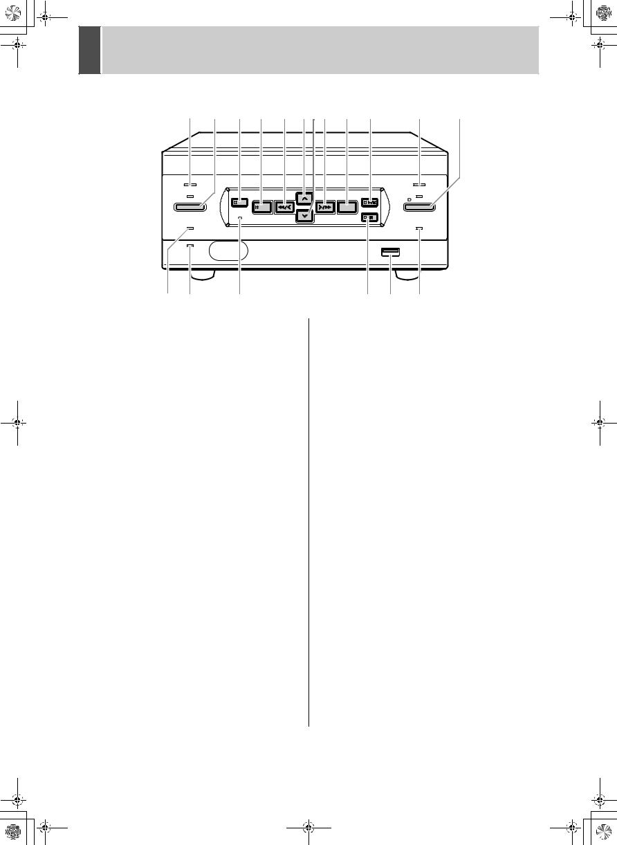
Front panel
1 |
2 |
3 |
4 |
5 |
6 |
7 |
8 |
9 |
10 |
11 |
12 |
POWER |
|
|
|
|
|
|
|
|
|
ALARM |
|
|
|
SEARCH |
|
|
|
|
|
|
PLAY/ |
|
|
TIMER |
|
MENU |
REVIEW |
|
|
CUE |
EXIT/OSD |
STOP |
REC/STOP |
|
|
|
|
|
|
|
|
||||||
|
|
|
|
|
|
|
|
|
|
||
|
|
|
|
|
|
|
|
|
STILL |
|
|
MENU RESET
|
FULL |
|
|
LAN |
|
|
(LINK/ACT.) |
|
13 |
14 |
15 |
|
|
LOCK/REMOTE |
|
USB |
|
16 |
17 |
18 |
1.POWER indicator
Lights when the power is ON.
Flashes when there is a problem with the hard disk or fan. (JP.10)
2.[TIMER] button and indicator (JP.14)
When the button is pressed while recording or stopped, the digital video recorder enters timer record standby, and the indicator lights. When the set time arrives, the digital video recorder starts timer recording.
3.[SEARCH] button and indicator (JP.18)
When the button is pressed while recording or stopped, the indicator lights, and the search setting screen appears.
4.[MENU] button
Used to display the menu screens (setting screens). The indicator lights when a menu screen is displayed.
5.[REVIEW] button
When pressed during playback, lets you rewind the image while watching it on screen. Also used for menu screen operations.
6.[ ] button
Used to move the cursor in menu screens up. Also used to change setting values.
7.[ ] button
Used to move the cursor in menu screens down. Also used to change setting values.
8.[CUE] button
When pressed during playback, lets you fast-forward the image while watching it on screen. Also used for menu screen operations.
9.[EXIT/OSD] button
Returns to the normal screen when the main menu or a sub-menu is displayed.
10.[PLAY/STOP] button
Plays back the normal image (indicator lights). When pressed during playback, stops playback.
11.ALARM indicator
Flashes when recording an alarm image.
12.[REC/STOP] button and indicator
Starts normal recording. Indicator lights during recording.
During recording, pressing the button for at least 3 seconds stops recording and turns off the indicator.
13.FULL indicator (JP.14)
Lights when the remaining memory in the hard disk’s recording area has reached zero and recording has stopped.
14.LAN indicator
Lights when the digital video recorder is connected to a network. Flashes when data is being sent and received.
15.[MENU RESET] button (JP.22)
Used to initialize the currently displayed menu settings, and to set the time.
16.[STILL] button
When pressed during playback, freezes the screen image (the indicator lights). Pressing the button again resumes playback.
17.USB terminal (JP.40)
Used to connect a CompactFlash memory card reader.
18.LOCK/REMOTE indicator (JP.21, P.34)
Lights when operations have been locked by the key lock or security lock setting.
If an operation button is pressed when the security lock is set, a buzzer sounds. The key lock cannot be set during playback.
The indicator flashes at 1Hz when there is a network connection, and flashes at 4Hz when there is a network connection while locked.
7
01e_dsr_m800_6.fm Page 8 Saturday, April 5, 2003 2:34 PM |
2 NAMES AND FUNCTIONS OF PARTS |
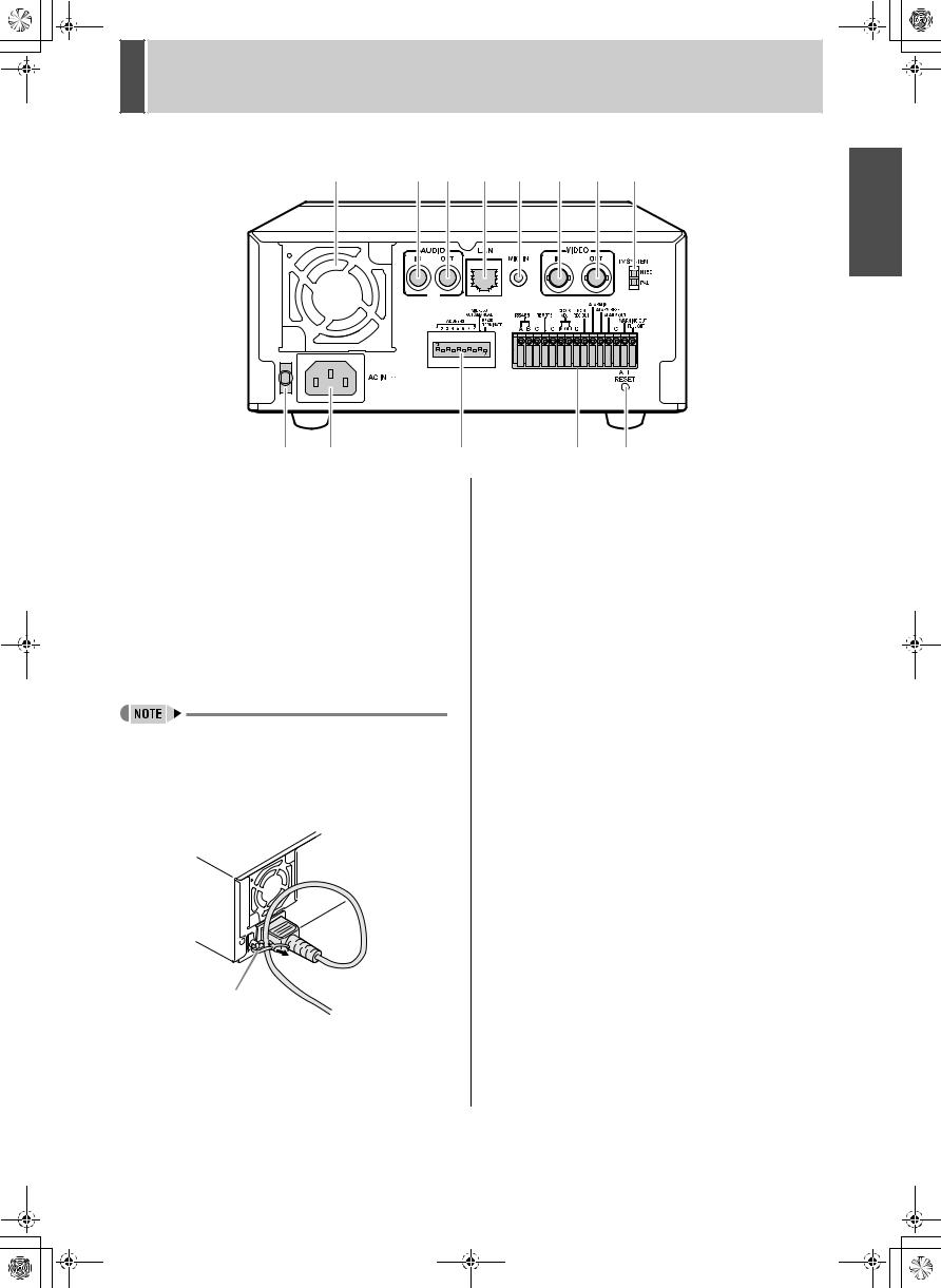
Rear panel
1 |
2 |
3 |
4 |
5 |
6 |
7 |
8 |
9 |
10 |
11 |
12 |
13 |
INTRODUCTION
1.FAN
2.AUDIO IN terminal
3.AUDIO OUT terminal
4.LAN terminal (JP.37)
5.MIC IN terminal
6.VIDEO IN terminal
7.VIDEO OUT terminal
8.TV SYSTEM selector switch
Used to select the video signal between NTSC and PAL systems for the camera input and TV monitor output connected to the digital video recorder.
zTurn the power OFF then ON again after selecting NTSC or PAL.
9.Power cord holder
Secure the power cord to the holder using the cord tie (accessory) as shown in the illustration.
Cord tie
10.AC INLET
AC power input terminal (3-core)
11.Dip switches (JP.37)
ADDRESS |
Used to set the device address of the |
|
TCP/IP or RS-485 (SSP) interface. |
ADDRESS AUTO |
Used to select whether to acquire the |
MANUAL |
IP address by automatic allocation, or |
|
to specify the lowest-order byte of the |
|
address using the dip switches. |
RS485 TERMINATE |
RS-485 termination ON/OFF switch |
|
|
12.Control and alarm terminals
Pin |
Signal |
RS485A |
To RS-485 terminal signal A *1 |
RS485B |
To RS-485 terminal signal B *1 |
C |
Common *1 |
REMOTE |
For wired remote control (VA-RMN01) |
C |
Common |
CLOCK ADJ IN |
Input for clock setting |
CLOCK ADJ OUT |
Output for clock setting |
C |
Common |
NON REC OUT |
NON-REC output |
ALARM IN |
Alarm input |
ALARM RESET |
Alarm reset input |
ALARM OUT |
Alarm output |
C |
Common |
WARNING OUT |
Warning output *2 |
FULL OUT |
Recording area full warning |
|
|
*1 Used for twisted-pair cable connection. *2 The following warnings are output:
zHard disk drive error z Fan error z Recording error
zNo input signal when VIDEO LOSS is ON.
13.ALL RESET switch
Resets the clock and backup mode setting.
8

01e_dsr_m800_6.fm Page 9 Tuesday, March 11, 2003 10:19 AM |
|
3 |
INSTALLATION AND CONNECTIONS |
This section describes how to connect the digital video recorder to the CCTV camera and other devices. Be sure to read the instruction manuals for each connected device. Make connections carefully. Improper connections can cause smoke or malfunctions.
Basic connections
The connections for the camera, TV monitor, microphone and PC are shown below.
CCTV camera (sold separately)
PC or hub
|
Microphone |
Video input |
|
Amp |
terminal |
||
|
|||
|
|
TV monitor (sold separately)
Ferrite core: Attach to the set side of the TV monitor power cord (do not wind).
*Use a shielded LAN connection cable, and wind it once around the supplied ferrite core.
System controller connections
The connections for a system controller are shown below. Use a twisted-pair cable (sold separately) to connect rear panel control terminals A, B and C (ground). Connect signal A to signal A, and signal B to signal B.
|
|
|
|
|
|
|
|
|
ALARM IN |
|
|
||||||||
|
|
|
CLOCK |
NON |
|
ALARM RESET |
|
|
|||||||||||
RS485 REMOTE |
|
ADJ |
REC OUT |
|
|
|
ALARM OUT |
|
|
||||||||||
|
|
|
|
|
|
|
|
|
|
|
|
|
|
|
|
WARNING OUT |
|||
|
|
|
|
|
|
|
|
|
|
|
|
|
|
||||||
|
|
|
|
|
|
|
|
|
|
|
|
|
|
|
|
|
|
FULL OUT |
|
A B C |
C IN OUT C |
|
|
|
|
|
|
|
C |
|
|||||||||
|
|
|
|
|
|
|
|
|
|
|
|
|
|
|
|
|
|
|
|
|
|
|
|
|
|
|
|
|
|
|
|
|
|
|
|
|
|
|
|
|
|
|
|
|
|
|
|
|
|
|
|
|
|
|
|
|
|
|
|
Twisted-pair cable |
To signal B |
|
|
|
|
Ground |
To signal A |
RS-485 |
|
|
|
|
|
terminal |
System controller (sold separately)
zTwisted-pair cable
Can reduce interference on the signal caused by noise generated by other cables.
9
Connecting a remote control circuit
The connections for a remote control circuit are shown below. Making the connections shown below lets you operate the digital video recorder by remote control.
zCreate the remote control circuit shown in the illustration, and connect it to the remote control input terminals (among the control terminals).
|
|
|
|
|
|
|
|
RO 1.2K |
|
|
|
|
|
|
|
|
|
|
|
|
R1 |
0.3K |
SW1:STOP |
|
|
|
|
|
VIDEO |
|
|
|
R2 |
0.43K |
SW2:PAUSE/EXIT |
|
||
MIC IN |
|
|
|
|
|
R3 |
0.51K |
SW3:REW |
|
|
||
|
|
IN |
|
OUT |
|
TV SYSTEM |
|
|
||||
|
|
|
|
|
|
|
NTSC |
R4 |
0.62K |
SW4:FF |
|
|
|
|
|
|
|
|
|
PAL |
|
|
|||
|
|
|
|
ALARM IN |
|
R5 |
0.75K |
SW5:PLAY |
|
|
||
RS485 |
REMOTE |
CLOCK |
NON |
ALARM RESET |
R6 |
0.91K |
SW6:REC |
|
|
|||
ADJ |
REC OUT |
|
|
WARNING OUT |
|
|
||||||
|
ALARM OUT |
|
|
|
|
|
||||||
A B C |
C IN OUT C |
|
C |
FULL OUT |
R7 |
1.1K |
SW7:MENU |
|
|
|||
|
|
|
|
|||||||||
|
|
|
|
|
|
|
|
|
|
|||
|
|
|
|
|
|
|
|
R8 |
1.3K |
SW8:SEARCH (REVERSE) |
||
|
|
|
|
|
|
RESET |
R9 |
2.0K |
SW9: |
|
|
|
|
|
|
|
|
|
|
ALL |
|
|
|
|
|
|
|
|
|
|
|
|
|
R10 2.4K |
SW10: |
|
|
|
|
|
|
|
|
|
|
|
R11 3.6K |
SW11: |
(SHIFT |
) |
|
|
|
|
|
|
|
|
|
R12 5.6K |
SW12: |
(SHIFT |
) |
|
( |
): When VA-RMN01 is used |
|
|
|
|
|||||||
Use a resistance of 1/10 ohms or more and with a D ranking (precision 0.5% or finer).
e_dsr_m800.book Page 10 Monday, February 3, 2003 10:51 AM |
|
3 |
INSTALLATION AND CONNECTIONS |
zConnect the cable of the wired remote control (VARMN01) (sold separately) to the remote control input terminals (among the control terminals).
Cut the plug off the cord, and connect the red wire to “REMOTE” and the bare wire to “C”.
RS485 REMOTE
A B C 
 C
C
Red wire |
Bare wire |
|
White |
||
|
||
wire |
|
VA-RMN01
Connecting cables to the control and alarm terminals
(1)Push in the lock pin with a flat-blade screwdriver.
(2)Insert the cable.
(3)Pull out the lock pin with a flat-blade screwdriver. The cable is now fixed in place.
Cable
Flat-blade screwdriver
Connecting to a network
The VA-SW800 application software (sold separately) lets you control the digital video recorder, and monitor live images, recorded images and audio through a network.
Connecting the power cord
1When you have finished making all the other connections, insert the power plug into the wall outlet.
There is no power switch. All the display indicators flash for approximately 30 seconds, then the POWER indicator lights. The monitor screen displays the camera image.
AUDIO |
|
LAN |
MIC IN |
|
VIDEO |
|
|
||
IN |
OUT |
|
|
|
IN |
|
OUT |
TV SYSTEM |
|
|
|
|
|
|
|
|
|
|
NTSC |
|
|
|
|
|
|
|
|
|
PAL |
|
|
|
|
|
|
|
ALARM IN |
|
|
|
|
ADDRESS |
RS485 REMOTE |
CLOCK |
NON |
ALARM RESET |
|||
|
|
AUTO/MANUAL |
ADJ |
REC OUT |
ALARM OUT |
||||
|
ADDRESS |
|
RS485 |
|
|
|
|
|
WARNING OUT |
1 |
2 3 4 5 6 |
7 8 |
|
A B C |
C IN OUT C |
C |
FULL OUT |
||
AC IN |
|
|
|
|
|
|
|
|
ALL |
|
|
|
|
|
|
|
RESET |
||
Power |
|
|
|
|
|
|
|
|
|
|
|
|
|||
* |
Ferrite core: Attach to the set |
||||||
cable |
|||||||
side of the DVR power cord |
|||||||
|
|
|
|
|
(do not wind). |
||
zWhen turning the power ON for the first time
"PLEASE SET THE CLOCK" is displayed on the monitor screen. Follow the steps on page 12 to set the clock.
z If the clock is already |
Operating display |
|
set |
||
|
||
The operation display |
|
|
area is displayed. |
|
zIf the POWER indicator flashes
The digital video recorder has a self-check function that indicates problems. If there is a problem at power ON or during operation, the type of problem is indicated by how rapidly the POWER indicator flashes. Contact a Sanyo Authorized Service Center if the POWER indicator flashes. 4 flashes per second:
The disk is checked automatically at power ON. If a hard disk problem is found, the POWER indicator flashes, and the hard disk must be replaced or reformatted. If you need to save images stored on the disk, contact a Sanyo Authorized Service Center.
1 flash per second: Fan problem
zIf you disconnect the power cable
Don’t move the digital video recorder for 30 seconds after power OFF.
The disk in the hard disk drive briefly keeps spinning after power OFF due to inertia, during which time the head is unstable. At this time, the disk is sensitive to shocks or vibrations, so avoid even light shocks.
INTRODUCTION
10
 e_dsr_m800.book Page 11 Monday, February 3, 2003 10:51 AM
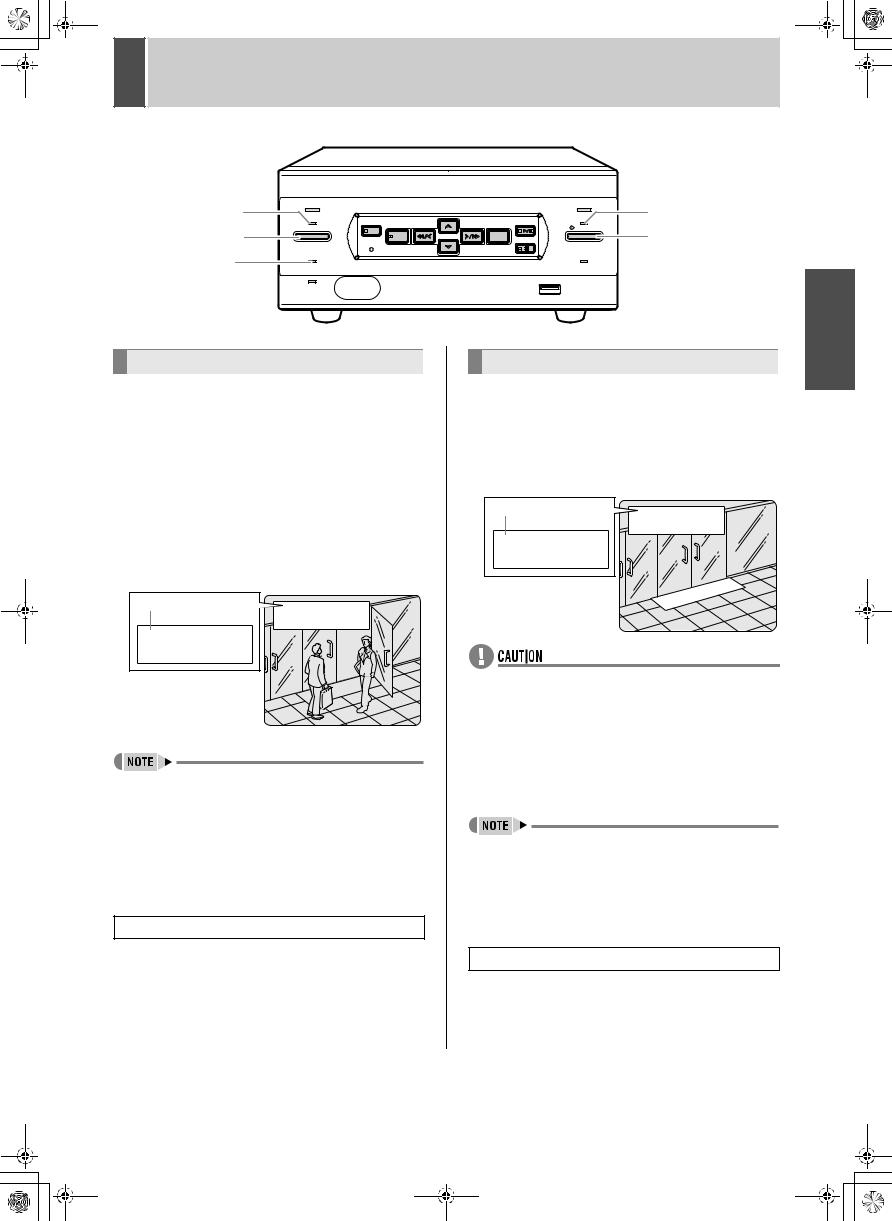
1 SCREEN DISPLAY AND POSITION
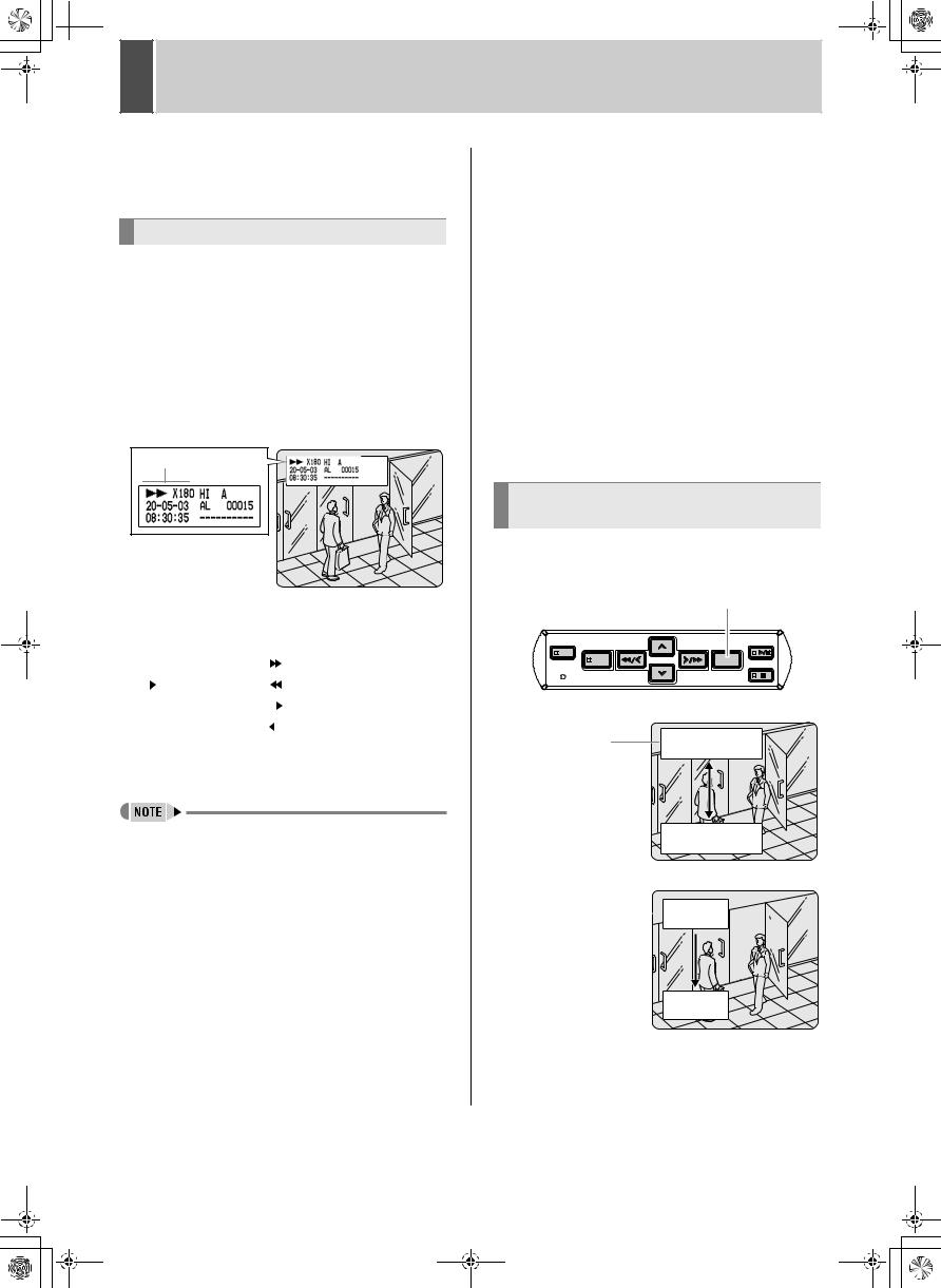
At power ON, the operation display area appears at the top left of the monitor screen.The operation display area shows the date/time, image quality, remaining time, and other information needed for operations.
Operation display area
Example: Normal screen
(1) |
|
(2) |
(3) |
|
(4) |
|
|
|||||||
(5) |
|
|
|
|
|
|
|
|
|
|
|
|
|
(7) |
|
|
|
|
|
|
|
|
|
|
|
|
|
||
|
|
|
|
|
|
|
|
|
|
|
|
|
||
|
|
|
|
|
|
|
|
|
|
|
|
|
||
|
|
|
|
|
|
|
|
|
|
|
|
|
||
|
|
|
|
|
|
|
|
|
|
|
|
|
|
|
|
|
|
|
|
|
|
|
|
|
|
|
|
|
|
|
|
|
|
|
|
|
|
|
|
|
||||
(6) |
|
|
|
(8) |
|
|
|
|
||||||
Playback screen
(1) |
(1)Operating symbol display
Displays the operation (such as recording or playback) and playback speed.
z : Recording |
|
|
|
|
|
: Fast-forward playback |
|||
|
|
|
: Playback |
|
|
|
|
|
: Rewind playback |
|
|
|
: Still |
|
|
|
|
|
: Slow playback |
|
|
|
|
||||||
|
|
|
|
|
|
|
|
|
: Reverse slow playback |
|
|
|
|
|
|
|
|
|
|
The playback speed is displayed during fast-forward or fast-rewind playback at 15 times the normal playback speed or faster, and during slow or reverse slow playback.
zDuring simultaneous recording and playback, the display indicates playback ( ).
).
(2)Image quality display (JP.27)
Displays the quality of the image that can be recorded on the hard disk. Set to “HIGH” in the initial settings.
(3)Audio recording
Displays “A” when audio recording has been set.
(4)Remaining time display
Unless “OVER WRITE” is set for recording, displays the remaining amount of recording time, as shown below.
Remaining time |
Displayed increment |
Example |
|
|
|
1 hour or more |
1 hour increments |
1H |
|
|
|
Less than 1 hour |
10 minute increments |
10M |
|
|
|
Less than 10 minutes |
1 minute increments |
1M |
|
|
|
(5)Date display (JP.13)
Shows the day/month/year.
20-05-03 (day/month/year)
(6)Time display (JP.13)
“00:00:00” is displayed when you turn the power ON for the first time. The digital video recorder uses the date and time to manage recording and playback points.
(7)Alarm display and alarm count display (JP.15)
When you set an alarm using the “Alarm recording” menu item, the alarm display area appears as shown below. z Alarm display
When alarm recording is set, “Alarm” appears. During alarm recording, the “Alarm” display flashes.
z Alarm count display
Displays the total number of alarms that have been generated.
(8)Name set for the digital video recorder
Displays the name set for the digital video recorder when it is controlled by a network.
Changing the position of the operating display
Press the [EXIT/OSD] button repeatedly.
Pressing the [EXIT/OSD] button repeatedly lets you move or erase the operation display area.
|
|
[EXIT/OSD] button |
|
SEARCH |
|
|
PLAY/ |
MENU REVIEW |
CUE EXIT/OSD |
STOP |
|
|
|
||
STILL
MENU RESET
Normal screen
Operation display area
Playback screen
Operation 

 display area


11
e_dsr_m800.book Page 12 Monday, February 3, 2003 10:51 AM |
|
2 |
SETTING THE LANGUAGE/CLOCK |
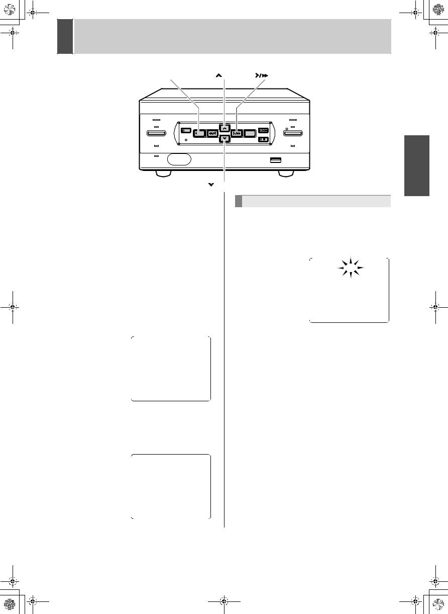
[MENU] button |
|
[ |
] button |
[ |
] button |
|
POWER |
|
|
|
|
ALARM |
|
SEARCH |
|
|
|
|
PLAY/ |
|
MENU |
REVIEW |
CUE |
EXIT/OSD |
STOP |
||
TIMER |
REC/STOP |
|||||
|
|
|
|
|||
|
|
|
|
|
STILL |
MENU RESET
FULL |
|
|
LOCK/REMOTE |
|
|
USB |
OPERATION |
LAN |
|
|
|
(LINK/ACT.) |
|
|
|
[ |
] button |
|
|
This section describes how to set the language displayed on the monitor and how to set the digital video recorder’s internal clock.
[Settings] ( indicates initial setting.)
|
Item |
Setting |
Description |
|
|
|
|
|
|
ENGLISH |
Sets the language to |
|
|
English. |
|
|
|
|
|
|
|
|
|
(1) |
LANGUAGE |
FRANCAIS |
Sets the language to French. |
|
|
DEUTSCH |
Sets the language to German. |
|
|
|
|
|
|
ESPAÑOL |
Sets the language to Spanish. |
|
|
|
|
(2) |
CLOCK SET |
|
Sets the date and time. |
|
|
|
|
1 Press the [MENU] button.
The [MENU] button lights, and the <MAIN MENU> screen appears.
2 Select, “1. LANGUAGE/CLOCK SET”, and press the [
 ] button.
The <LANGUAGE/LANGUE/SPRACHE/IDIOMA> screen appears.The cursor is positioned on ENGLISH.
To change the language
3 Press the [ 
 ] button, then the [
 ] or [
 ] button to select the desired language.
The set item flashes.
4 When you have made a selection, press the [ 
 ] button.
The cursor moves to the date and time. The language has now been set.
To return to the normal screen, press the [EXIT/OSD] button.
12
e_dsr_m800.book Page 13 Monday, February 3, 2003 10:51 AM |
|
2 |
SETTING THE LANGUAGE/CLOCK |
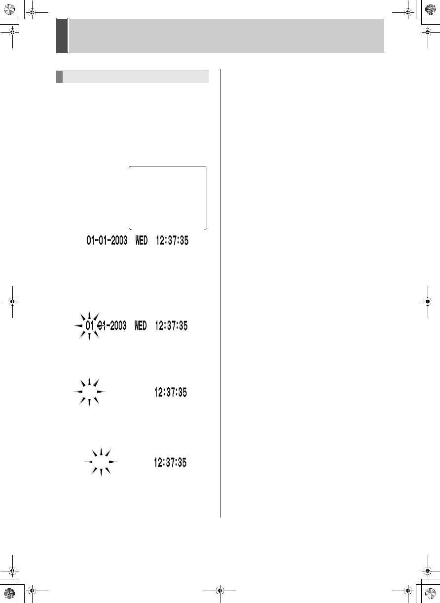
Setting the time
(Initial setting: 01-01-2003 WED 00:00:00)
Be sure to set the correct date and time. The digital video recorder stores the times of recordings for use in operations such as playback and search/playback.
Example: Setting 20 May 2003, 8:30
3 Press the [ ] or [
 ] button to move the cursor to the date and time under <CLOCK SET>.
|
|
|
|
|
|
|
|
|
|
|
|
|
|
|
|
|
|
|
|
YEAR WEEK |
TIME |
||||||
|
|
|
|
|
|
||||||||
|
MONTH |
|
|
||||||||||
DAY |
|
|
|||||||||||
4 Press the [
 ] button.
“01” (indicating the day) flashes.
5 Press the [ ] or [
 ] button to select “20”.
6 Press the [
 ] button.
“01” (indicating the month) flashes.
7 Use the same procedure to set the month (5 in this example), year (2003), hour (08) and minute (30)
When you have set the minute, the cursor moves to “MODE” under <SUMMER TIME>, and the clock starts from 00 seconds.
z“WEEK” is set automatically.
zThe time is stopped during clock setting.
8 Press the [EXIT/OSD] button.
The display returns to the normal screen.
13
02e_dsr_m800_6.fm Page 14 Saturday, April 5, 2003 2:40 PM |
|
3 |
NORMAL RECORDING/TIMER RECORDING |
TIMER indicator |
POWER |
|
|
|
|
ALARM |
REC indicator |
|
SEARCH |
|
|
PLAY/ |
|
||
|
TIMER |
MENU REVIEW |
CUE EXIT/OSD |
STOP |
REC/STOP |
[REC/STOP] button |
|
[TIMER] button |
|
|
|||||
|
|
|
|
||||
|
MENU RESET |
|
|
STILL |
|
||
|
|
|
|
|
|
|
|
FULL indicator |
FULL |
|
|
|
|
LOCK/REMOTE |
|
|
|
|
|
|
|
|
USB
LAN
(LINK/ACT.)
Normal recording
Follow the steps below to record the monitored image onto the hard disk.
1 Set the TV SYSTEM selector switch to PAL.
If it is set to NTSC, you will not be able to record the image correctly.
2 Press the [REC/STOP] button.
The REC indicator lights.“z” (the recording symbol) appears on the screen, and recording starts.
Recording symbol
zWhen you record for the first time, the initial settings are used. To change the image quality, see P.27.
zWhen the remaining space for recording reaches zero, recording ends and the FULL indicator lights. You can start recording from the beginning again by changing the “OVER WRITE” recording setting. (JP.27)
zYou can record and play back images at the same time. See P.16 for the procedure.
Ending normal recording
3 Press the [REC/STOP] button for about
3 seconds.
The REC indicator goes out and recording stops.
Timer recording
Follow the steps on the right to record the monitored image onto the hard disk at the set time.
1 Press the [TIMER] button.
The TIMER indicator lights, and the digital video recorder enters timer recording standby mode.
Recording symbol
zA warning tone sounds if timer recording hasn’t been set.
(1)See P.29 for how to set timer recording.
(2)When the time specified in the timer settings arrives, the REC indicator lights, “z” (the recording symbol) appears in the screen, and recording starts.
(3)When the set end time arrives, the REC indicator goes out, and recording stops.
zWhen the remaining memory space for recording reaches zero, recording ends, and the FULL indicator lights. You can start recording from the beginning again by changing the “OVER WRITE” setting. (JP.27)
zYou can record and play back images at the same time. See P.16 for the procedure.
Stopping during timer recording
2 Press the [TIMER] button.
The [TIMER] indicator goes out and recording ends.
OPERATION
14
 Loading...