

Page 1

© 2009 Sanyo Manufacturing Corporation
Model No.: / No. de Modelo:
DP37819
Table of Contents
Tabla de contenido4421
21
Part No. / No. de parte : 1JC6P1P0342- -1JC6P1P0342- -
1080p LCD HDTV
TVHD 1080p de LCD
3737”
Owner’s ManualOwner’s Manual
Manual del usuarioManual del usuario
Page 2
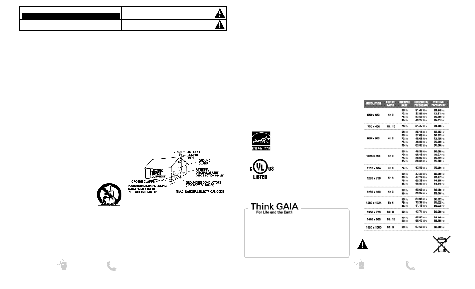
“As an Energy Star® Partner, Sanyo
Manufacturing Corporation has determined that this product meets the Energy
Star® guidelines for energy efficiency.”
This symbol on the nameplate means
the product is Listed by Underwriter’s
Laboratories Inc. It is designed and
manufactured to meet rigid U.L. safety
standards against risk of fire, casualty
and electrical hazards.
3
Need help? www.sanyoctv.com 1-800-877-5032
2
Need help? www.sanyoctv.com 1-800-877-5032
1. Read these instructions.
2. Keep these instructions.
3. Heed all warnings.
4. Follow all instructions.
5. Do not use this apparatus near water.
6. Clean only with dry cloth.
7. Do not block any ventilation openings. Install in
accordance with the manufacturer’s instructions.
8. Do not install near any heat sources such as radiators,
heat registers, stoves, or other apparatus (including
amplifiers) that produce heat.
9. Do not defeat the safety purpose of the polarized or
grounding-type plug. A polarized plug has two blades with
one wider than the other. A grounding-type plug has two
blades and a third grounding prong. The wide blade or the
third prong are provided for your safety. If the provided
plug does not fit fully into your outlet, consult an electrician for replacement of the obsolete outlet.
10. Protect the power cord from being walked on or
pinched particularly at plugs, convenience receptacles,
and the point where they exit from the apparatus.
11. Only use attachments/accessories specified by the
manufacturer.
12. Use only with the cart, stand, tripod,
bracket, or table specified by the manufacturer, or sold with the apparatus.
When a cart is used, use caution when
moving the cart/apparatus combination
to avoid injury from tip-over.
13. Unplug this apparatus during lightning storms or when
unused for long periods of time.
14. Refer all servicing to qualified service personnel.
Servicing is required when the apparatus has been
damaged in any way, such as power-supply cord or
plug is damaged, liquid has been spilled or objects have
fallen into the apparatus, the apparatus has been
exposed to rain or moisture, does not operate normally,
or has been dropped.
15. If an outside antenna is connected to the television
equipment, be sure the antenna system is grounded so
as to provide some protection against voltage surges
and built up static charges. In the U.S. Selection 810-21
of the National Electrical Code provides information with
respect to proper grounding of the mast and supporting
structure, grounding of the lead-in wire to an antenna
discharge unit, size of grounding conductors, location of
antenna discharge unit, connection to grounding electrodes, and requirements for the grounding electrodes.
16. An outside antenna system should not be located in the
vicinity of overhead power lines or other electrical light
or power circuits, or where it can fall into such power
lines or circuits. When installing an outside antenna
system, extreme care should be taken to keep from
touching such power lines or circuits as contact with
them might be fatal.
EXAMPLE OF ANTENNA GROUNDING ACCORDING
TO NATIONAL ELECTRICAL CODE, ANSI/NFPA 70
“Note to CATV system installer:
This reminder is provided to call the CATV system installer’s
attention to Article 820-40 of the NEC that provides guidelines
for proper grounding and, in particular, specifies that the cable
ground shall be connected to the grounding system of the
building, as close to the point of cable entry as practical.”
17. Wall or Ceiling Mounting—The product should be
mounted to a wall or ceiling only as recommended by
the manufacturer.
18. Apparatus shall not be exposed to dripping or splashing
and no objects filled with liquids, such as vases, shall be
placed on the apparatus.
19. When the MAINS plug is used as the disconnect device,
the disconnect device shall remain readily operable.
CAUTION
RISK OF ELECTRIC SHOCK DO NOT OPEN!
CAUTION: TO REDUCE THE RISK OF ELECTRIC SHOCK, DO NOT REMOVE COVER (OR
BACK). NO USER-SERVICEABLE PARTS INSIDE. REFER SERVICING TO QUALIFIED SERVICE PERSONNEL.
THIS SYMBOL INDICATES THAT DANGEROUS VOLTAGE CONSTITUTING A
RISK OF ELECTRIC SHOCK IS PRESENT WITHIN THIS UNIT.
THIS SYMBOL INDICATES THAT THERE ARE IMPORTANT OPERATING AND
MAINTENANCE INSTRUCTIONS IN THE LITERATURE ACCOMPANYING THIS
UNIT.
WARNING: TO REDUCE THE RISK OF FIRE OR ELECTRIC SHOCK, DO NOT EXPOSE THIS APPLIANCE TO
RAIN OR MOISTURE.
IMPORTANT SAFETY INSTRUCTIONS
FCC INFORMATION
This equipment has been tested and found to comply with the limits for a Class B digital device, pursuant to Part 15
of the FCC Rules. These limits are designed to provide reasonable protection against harmful interference in a
residential installation. This equipment generates, uses and can radiate radio frequency energy and, if not installed
and used in accordance with the instructions, may cause harmful interference to radio communications. However,
there is no guarantee that interference will not occur in a particular installation. If this equipment does cause
harmful interference to radio or television reception, which can be determined by turning the equipment off and on,
the user is encouraged to try to correct the interference by one or more of the following measures:
– Reorient or relocate the receiving antenna.
– Increase the separation between the equipment and receiver.
– Connect the equipment into an outlet on a circuit different from that to which the receiver is connected.
– Consult the dealer or an experienced radio/TV technician for help.
CAUTION: FCC Regulations state that improper modifications or unauthorized changes to this unit may void
the user’s authority to operate the unit.
TRADEMARKS
Manufactured under license from Dolby Laboratories.
“Dolby” is a trademark of Dolby Laboratories.
CONTAINS MERCURY LAMPS,
DISPOSE OF PROPERLY
SANYO recommends keeping the TV set at its
factory settings or moving Energy Saver settings
from “Level 1” to “Level 2” or “Level 3” to further
reduce power requirements and increase energy
savings. Doing so contributes to the sustainability
of our resources and environment.
For more information visit www.energystar.gov
PC RESOLUTION CHART
HDMI, the HDMI Logo and High-Definition Multimedia
Interface are trademarks or registered trademarks of
HDMI Licensing LLC.
This Class B digital apparatus complies with Canadian
ICES-003.
Page 3
54
Need help? www.sanyoctv.com 1-800-877-5032
Need help? www.sanyoctv.com 1-800-877-5032
CONTENTS
IMPORTANT SAFETY INSTRUCTIONS . . . . . . . . . . . . . . . 2
FCC INFORMATION . . . . . . . . . . . . . . . . . . . . . . . . . . . . . . . .3
TRADEMARKS . . . . . . . . . . . . . . . . . . . . . . . . . . . . . . . . . . . .3
THINK GAIA . . . . . . . . . . . . . . . . . . . . . . . . . . . . . . . . . . . . . .3
SPECIFICATIONS . . . . . . . . . . . . . . . . . . . . . . . . . . . . . . . . . .3
DISPOSAL . . . . . . . . . . . . . . . . . . . . . . . . . . . . . . . . . . . . . . . .3
PC RESOLUTION CHART . . . . . . . . . . . . . . . . . . . . . . . . . . . .3
PROTECTING THE LCD SCREEN . . . . . . . . . . . . . . . . . . . . . .4
PRECAUTIONS . . . . . . . . . . . . . . . . . . . . . . . . . . . . . . . . . . . .4
CONTENTS . . . . . . . . . . . . . . . . . . . . . . . . . . . . . . . . . . . . . . .4
STAND REMOVAL / WALL MOUNTING . . . . . . . . . . . . . . .5
GETTING STARTED—
Remote Control Battery Installation . . . . . . . . . . . . . . . .5
Antenna Connections for off-air or cable . . . . . . . . . . .5
Remote Control operation . . . . . . . . . . . . . . . . . . . . . . . .6
PC CONNECTIONS . . . . . . . . . . . . . . . . . . . . . . . . . . . . . . . . .7
PC MENU OPERATION . . . . . . . . . . . . . . . . . . . . . . . . . . . . .7
BACK PANEL JACKS . . . . . . . . . . . . . . . . . . . . . . . . . . . . . . .8
AUDIO / VIDEO CONNECTIONS . . . . . . . . . . . . . . . . . . . . . .9
POWER CONNECTION / INITIAL CHANNEL SEARCH . .10
ON-SCREEN MENU OPERATION—
Chanel Setting . . . . . . . . . . . . . . . . . . . . . . . . . . . . . . . . .11
Channel Search . . . . . . . . . . . . . . . . . . . . . . . . . . . . .11
Channel Scan Memory . . . . . . . . . . . . . . . . . . . . . . .11
Setup . . . . . . . . . . . . . . . . . . . . . . . . . . . . . . . . . . . . . . . . .12
Menu Language . . . . . . . . . . . . . . . . . . . . . . . . . . . . .12
Digital Caption . . . . . . . . . . . . . . . . . . . . . . . . . . . . . .12
V-Chip . . . . . . . . . . . . . . . . . . . . . . . . . . . . . . . . . . . . . .13
Energy Saver . . . . . . . . . . . . . . . . . . . . . . . . . . . . . . . .14
Clock Timer . . . . . . . . . . . . . . . . . . . . . . . . . . . . . . . . .14
HDMI Linking . . . . . . . . . . . . . . . . . . . . . . . . . . . . . . .14
Picture . . . . . . . . . . . . . . . . . . . . . . . . . . . . . . . . . . . . . . . .15
Manual Picture Settings . . . . . . . . . . . . . . . . . . . . . .15
aaSound . . . . . . . . . . . . . . . . . . . . . . . . . . . . . . . . . . . . . . . . .16
Manual Sound Settings . . . . . . . . . . . . . . . . . . . . . . .16
PHOTO VIEWER . . . . . . . . . . . . . . . . . . . . . . . . . . . . . . . . . .17
WARRANTY . . . . . . . . . . . . . . . . . . . . . . . . . . . . . . . . . . . . . .18
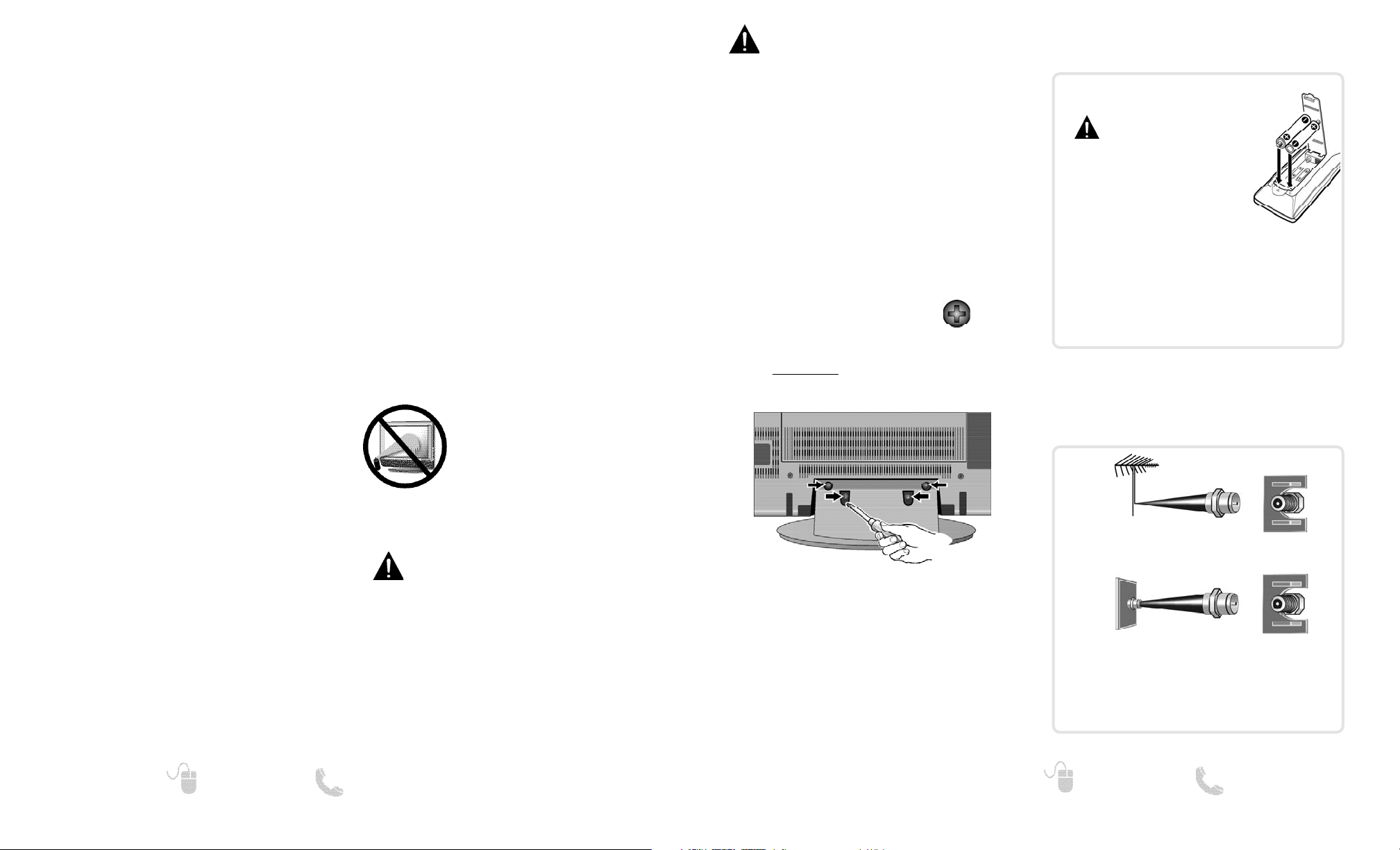
STAND REMOVAL AND WALL
MOUNTING
(OPTIONAL)
Wall mounting of the HDTV must be performed
by a skilled person.
Tools Needed: Phillips screwdriver
IMPORTANT NOTE:
Before taking off the screws and stand, place the
HDTV face down
on a padded or cushioned
surface to protect the screen and finish.
No. 3
PROTECTING THE LCD SCREEN
The screen can be damaged if it is
not maintained properly. Do not use
hard objects such as hard cloth or
paper. Do not use excessive pressure
when cleaning the screen; excessive
pressure can cause permanent discoloration or dark spots.
NEVER spray liquids on the screen.
POSITIONING THE LCD
HDTV
Always use a firm-flat surface when positioning
your HDTV.
Do not position the unit in a confined area.
Allow adequate space for proper ventilation.
SPECIFICATIONS
Power Requirement:
Source: AC 120V, 60Hz
AC Power Consumption: 142 W
Dimensions:
MODEL WIDTH HEIGHT DEPTH
DP37819 35.5 24.0 12.1
w/o stand 25.9 4.7
NOTE: Dimensions are in inches
1
Remove the four (4) screws securing the foot
stand. CAUTION: Hold the stand firmly as you
remove the last screw.
2
Use the screws you removed when
detaching the stand to secure the HDTV to a
wall mounting kit (not included.)
VESA standard interface: 400 x 400
Mounting screws measurements:
M6 (6mm) Diameter, Length—16mm (maximum)
HANDLING PRECAUTIONS
• Handle by the cabinet only. Never touch the
screen when handling.
• Excessive pressure on the screen can cause per-
manent discoloration or dark spots.
• Handling damage is not covered under warranty.
GETTING STARTED
The tuner in this HDTV can receive:
• Digital and Analog off air signals from an antenna
• Analog or ClearQAM cable channels from a direct
Cable TV connection.
ANTENNA CONNECTION FOR
OFF-AIR SIGNALS OR CABLE
CABLE
ANALOG / DIGITAL
ANTENNA IN
BATTERY INSTALLATION
Install batteries in the remote control
( 2 “AAA”, not included)
PRECAUTIONS
To ensure safe operation, please
observe the following precautions:
• Replace both batteries at the same
time. Do not use a new battery
with a used battery.
• There’s a risk of explosion if a battery is replaced by
an incorrect type.
• Do not expose the Remote Control unit to moisture
or heat.
• Be sure to match the “+” and “
–” signs on the
batteries with marks inside the remote control.
ANTENNA
Page 4
76
Need help? www.sanyoctv.com 1-800-877-5032
Need help? www.sanyoctv.com 1-800-877-5032
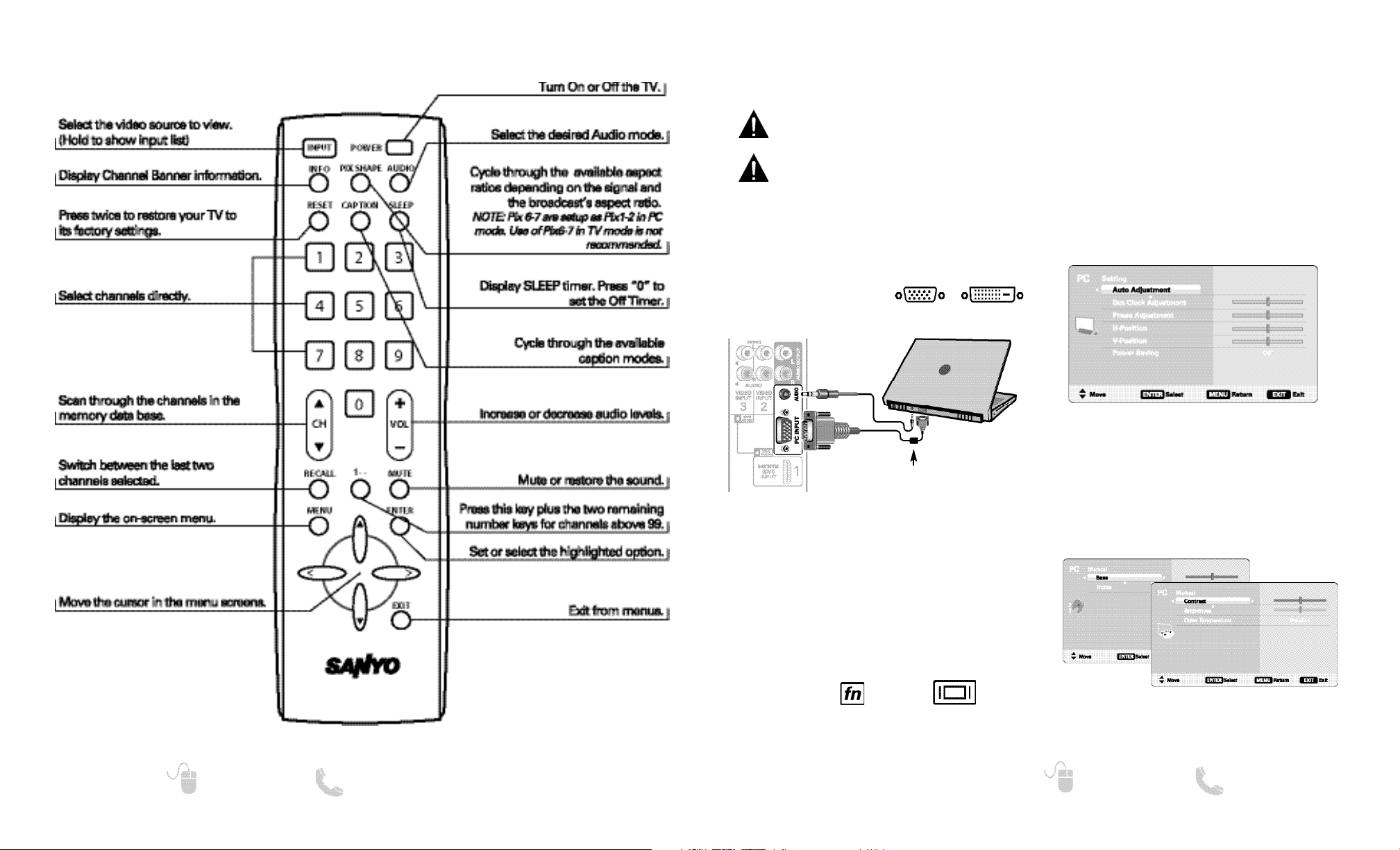
REMOTE CONTROL OPERATION
PC CONNECTIONS AND SETUP
PC PICTURE AND SOUND SCREENS
PC SETTING SCREEN
PC Setting
Auto Adjustment – Automatically adjusts display
position, dot clock, and phase.
Dot Clock – Adjust the Dot frequency to match
your computer’s Dot frequency.
Phase – Adjust this parameter when the picture
appears to flicker or is blurred.
H-Position – Move the image horizontally.
V-Position – Move the image vertically.
Power Saving – Enable the HDTV to turn to
Standby Mode when computer is not in use.
PC Picture and Sound
Standard – Sets predetermined values to the
Picture or Sound parameters.
Manual – Adjust Contrast, Brightness, and Color
Temperature screen settings, and the Bass and
Treble audio settings.
NOTE: These settings do not affect normal TV viewing.
Laptop Display
When using your Sanyo HDTV to display a
Laptop’s screen display, holding down the Fn (or
FN) key while pressing the appropriate function
key (F5, F7, F8, etc) should cycle through different
display modes between the laptop and the HDTV.
Modes may include displaying only on the laptop
screen, on both the laptop and the HDTV, or
displaying only on the HDTV.
NOTE: Fn key and function key symbols on the laptop’s
keyboard may vary from one brand to another.
Hold down and press
PC OR LAPTOP
HDTV BACK
RGB Monitor
cable
Stereo mini
audio cable
Sanyo recommends using a
monitor cable that includes
a Ferrite Core.
Before connecting any cables, disconnect the
AC power cords of both the HDTV and PC from
the AC outlets.
Power on the HDTV and any other peripheral
equipment before powering on the computer.
To avoid an “Out of Range” condition please set
your PC’s output resolution to one compatible with
your HDTV. See PC Resolution chart on page 3.
NOTE: If computer has only DVI Output, a DVI to RGB
converter will be required (not included.)
DVI OUTPUT
JACK
RGB OUTPUT
JACK
Use your HDTV as a computer monitor by hooking
up your PC or Laptop to the TV with the use of an
appropriate monitor cable.
Page 5
8
Need help? www.sanyoctv.com 1-800-877-5032
9
Need help? www.sanyoctv.com 1-800-877-5032
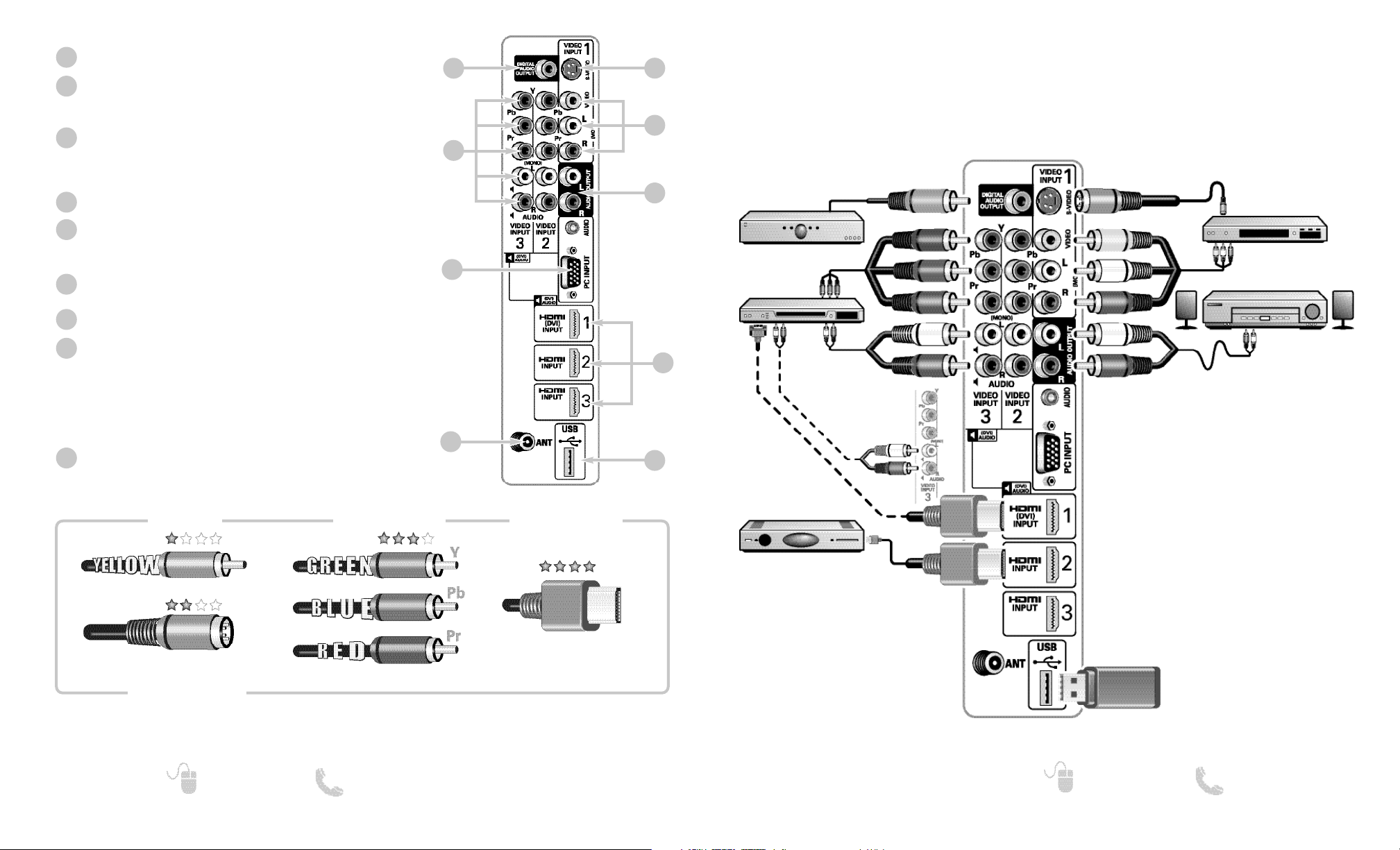
AUDIO / VIDEO CONNECTIONS
Digital Audio Output (Coaxial)
Component Video Input (VIDEO2 or VIDEO3)
Green (Y), blue (Pb), and red (Pr) Video inputs plus the
white and red Audio inputs.
PC Input and Stereo Audio (Mini)
• MONITOR RGB (D-SUB)
• AUDIO R/L (Stereo Mini Jack)
Analog / Digital Antenna Input
S-Video Input (VIDEO1)
NOTE: An S-Video connection will override a connection to
the Video1 (yellow) input jack.
Composite Video Input (VIDEO1)
Yellow (Video), plus white and red (Audio) input jacks.
Stereo Audio Out (L/R) Jacks
HDMI (INPUT1, 2 & 3)
An all digital AV interface that can accept
uncompressed video signals up to 1080p for
the very best picture possible.
NOTE: A DVI conection is possible via the HDMI (DVI)
INPUT1 using an appropriate adapter and also
connecting the audio to the VIDEO3 Audio jacks.
USB Input
View pictures stored in a USB flash drive.
1
2
3
4
5
6
7
8
9
1
2
3
4
5
7
9
6
BACK PANEL JACKS
8
DVD PLAYER
(or similar device)
VCR
(or analog device)
STEREO
AMPLIFIER
MULTICHANNEL
RECEIVER
NOTE: Audio/Video cables are not supplied
Composite connections are used to hookup
your analog equipment such as a VCR or an
older DVD player.
S-Video connection can replace the yellow
Video connection for enhanced video.
Digital Audio Output is used to hookup a
multichannel receiver with the use of a phonotype digital audio cable.
Component connections will accept SDTV,
EDTV and HDTV video signals. Use them for
great image quality from digital devices.
SATELLITE RECEIVER
(or similar device)
USB DEVICE
Audio Output L/R are used to hookup an
external stereo Amplifier. (Do not connect
external speakers directly to the HDTV)
HDMI INPUT1, 2 & 3 are used to hookup HD
digital devices such as a Blu-ray player, HD
Cable Box, HD Satellite Receiver or Videogame System.
HDMI (DVI) INPUT1 can be used to hookup
a DVI device with the use of an appropriate
adapter. (VIDEO3 Audio in L/R jacks need to
be hooked up to the DVI device as well)
USB input jack is used to
connect a USB mass
storage device to watch
JPEG images on your
HDTV.
DVI
Composite
S-Video
Component
H D M I
NOTE: Composite, S-Video, and Component video connections need their appropriate white and
red audio connections. High Definition image available from HD signals and HD equipment.
Above Standard
Standard High Definition
Optimum
High Definition
NOTE: Use the INPUT key on your
remote control to select the
desired input.
Page 6
11
Need help? www.sanyoctv.com 1-800-877-5032
10
Need help? www.sanyoctv.com 1-800-877-5032
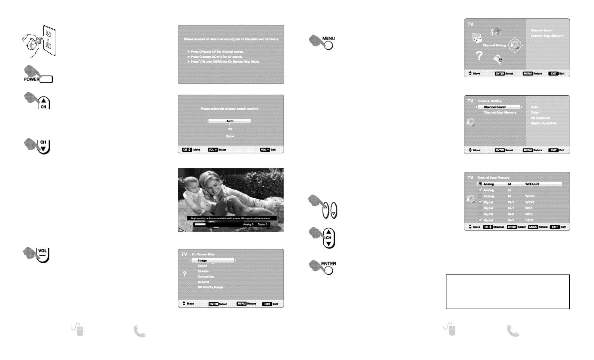
GETTING STARTED— INITIAL CHANNEL SEARCH (FIRST POWER ON)
Turn On TV
Wait for on-screen instructions to
perform an Initial Channel Search.
CHANNEL SEARCH
Checks Antenna and Cable signals
connected to the Antenna terminal.
AV SEARCH
Searches for signals from devices
connected to the AV input jacks.
NOTE: Power ON external devices connected to the TV
before commencing an AV Search.
An AV search will begin if no Antenna signals are
detected, if neither of these searches detect signals,
the HDTV will tune to input Video1.
Plug in AC power cord
120V AC, 60Hz
INITIAL SETUP SCREEN
CHANNEL SEARCH METHOD SCREEN
CHANNEL SEARCH PROGRESS SCREEN
NOTE: “Auto” detects the mode detection, Cable or Air, first,
and then proceeds with the channel search.
ON SCREEN HELP MENU
CHANNEL SETTING
Auto – Searches the detected mode, Cable or Air.
Cable – Searches for analog and unscrambled
(ClearQAM) digital cable channels.
Air (Antenna) – Searches for analog and digital off-air
channels.
Digital Air Add-On – Searches digital off-air channels
adding newly found digital channels to the channel
map database.
CHANNEL SETTING SCREEN
MAIN MENU SCREEN
CHANNEL SEARCH
Display the On Screen menu and use the
CURSOR keys to select Channel
Setting. Press ENTER.
NOTE: Digital Air Add-On option is not available when the
current mode is Cable.
ON-SCREEN MENU OPERATION
Channel Scan Memory lists all Analog and Digital
channels found. It also lists Analog channels that were
not found, which can be added.
CHANNEL SCAN MEMORY
CHANNEL SCAN MEMORY SCREEN
Move the channel select bar
through all channels, enabled and
disabled.
Move the channel select bar
through enabled channels, skipping
all disabled channels.
Enable a disabled channel or disable
an enabled one.
NOTE: For information on local digital channels,
visit www.antennaweb.org
IMPORTANT FACT: This HDTV maintains only one database of digital channels. Therefore, when you search for
cable channels, the database of antenna digital channels
will be deleted. You will only be able to receive those
ClearQAM channels your cable company provides.
Access an on screen trouble shooting
guide (in the Initial Setup Screen.)
NOTE: You may access the On Screen Help
menu later on at any time via the main
menu.
Page 7

1312
Need help? www.sanyoctv.com 1-800-877-5032
Need help? www.sanyoctv.com 1-800-877-5032
SETUP
Display the On Screen menu and use the
CURSOR keys to select Setup. Press
ENTER.
ON-SCREEN MENU OPERATION
Choose between English, Spanish and French for your
On Screen menu’s display language. Press ENTER on
the desired language.
MENU LANGUAGE
MAIN MENU SCREEN
SETUP MENU LANGUAGE SCREEN
A blue marker indicates the current
selected option.
DIGITAL CAPTION SCREEN
Use the Setup menu to set the desired Menu
Language, V-Chip rating settings, customize Digital
Captions, set Energy Saver level, or set the current
time and on-time with the Clock Timer.
Captioning is textual information transmitted along
with the picture and sound. Turning Captioning ON
causes the HDTV to open these captions (digital or
analog) and superimpose them on the screen.
Digital Caption’s Font, Background and Foreground
display may be customized:
DIGITAL CAPTION
Navigate the cursor
(highlight)
Select / set parameter.
NOTE: Local broadcasters decide which caption signals
to transmit.
SETUP
ON-SCREEN MENU OPERATION
Use this feature to automatically block programs with
content you deem as inappropriate for viewing by your
children.
V – CHIP
SETUP V-CHIP SCREEN
ADJUST (STANDARD) SCREEN
Navigate the cursor
(highlight)
Make selection.
Block or unblock the selected
Rating option.
NOTE: Blocking a rating will automatically block all higher
ratings. Unblocking a rating automatically unblocks
all lower ratings.
ADJUST (ADVANCED) SCREENS
Advanced V-Chip System
This feature is an advanced Regional rating system for
digital channels.
When the HDTV detects compatible Rating Region
Table (RRT) data, it’s downloaded & stored in memory.
The Setup V-Chip screen is then modified to show the
Adjust (Advanced) option.
Use the CURSOR and keys to highlight the
different options. Use the ENTER key to block or
unblock the selected rating.
NOTE: This feature is designed to comply with the United
States of America’s FCC V-Chip regulations. Therefore,
it may not function with broadcasts that originate in
other countries.
MORE INFORMATION
Additional information about MPAA (Motion Picture
Association of America) and V-Chip rating can be
found at: www.mpaa.org and www.v-chip.org,
respectively.
Page 8

15
Need help? www.sanyoctv.com 1-800-877-5032
14
Need help? www.sanyoctv.com 1-800-877-5032
SETUP
ENERGY SAVER SCREEN
Energy saver settings control the LCD backlight
brightness to save power consumption.
The higher the level number, the more brightness
reduction and higher power saving. Press ENTER on
the desired level.
ENERGY SAVER
Set the Current Time for your HDTV. You may also set
a Switch on Time to use with the On Timer Function.
When On Timer Function is set to ON, the TV will auto-
matically turn on at the previously set Switch on Time.
CLOCK TIMER
CLOCK TIMER SCREEN
ON TIMER FUNCTION SCREEN
Change the value of the current
selection.
Move to the next or previous value
that you wish to change.
Save the desired Time entry.
Set the On Timer Function ON or OFF.
ON-SCREEN MENU OPERATION
PICTURE
ON-SCREEN MENU OPERATION
Display the On Screen menu and use the
CURSOR keys to select Picture.
Press ENTER.
MAIN MENU SCREEN
You may choose between Movie, Sports, News,
Game, and Standard, which have predetermined fixed
picture parameter values, or one of the two Manual
options for customized personal settings.
NOTE: Each AV input can have its own picture mode (pre-
determined or manual.) Current input’s selected
option is indicated by a blue marker.
Choose Manual to adjust Color, Tint, Contrast,
Brightness, Sharpness, Signal Balancer, Noise
Reduction and Dynamic Contrast values.
Advanced Manual offers a Detailed Setting sub-menu
with the following options: Expanded DNR, White
Balance, Vertical Sharpness, Edge Enhancer, H-Size
and V-Size.
MANUAL PICTURE SETTINGS
Cycle through the different Picture
parameters.
Adjust the value of the selected
parameter.
Enter the selected parameter’s
adjustment screen.
Set the value of the selected
parameter and return to parameter
selection screen.
PICTURE SCREEN (MANUAL)
PARAMETER SELECTION SCREEN
Select Manual or Advanced Manual.
VALUE ADJUSTMENT SCREEN EXAMPLES
NOTE:
CURSOR keys select the next/previous
parameter without returning to the previous
menu screen.
Use the HDMI-CEC Function to enable or disable all
available CEC functions.
HDMI Power ON Sync and Power OFF Sync enable
specific features including the automatic power ON
process and power OFF process.
HDMI LINKING
HDMI LINKING SCREEN
NOTE: Designed for use with a Sanyo Xacti Digital
VIdeo/Movie Camera, and may not support all HDMICEC functions of other equipment.
The CEC (Consumer Electronics Control) feature
allows the control of multiple CEC-enabled devices
with one remote control, and the interaction of
devices with each other without user intervention.
Page 9

16
Need help? www.sanyoctv.com 1-800-877-5032
17
Need help? www.sanyoctv.com 1-800-877-5032
SOUND
Display the On Screen menu and use the
CURSOR keys to select Sound.
Press ENTER.
Choose one of the four available options for your
sound settings:
Auto – Sound setting levels are adjusted and linked
according to the current Picture option.
Standard – Neutral values for sound parameters.
Manual – Set Bass and Treble levels to your preference.
Advanced Manual – Use the 4-Band Equalizer to
personalize sound settings.
MAIN MENU SCREEN
MANUAL PARAMETER SCREEN
ADVANCED MANUAL PARAMETER SCREEN
VALUE ADJUSTMENT SCREEN EXAMPLES
Cycle through the different Sound
parameters.
Adjust the value of the selected
parameter.
Enter the selected parameter’s
adjustment screen.
Set the value of the selected
parameter and return to parameter
selection screen.
Select Manual or Advanced Manual.
ON-SCREEN MENU OPERATION
MANUAL SOUND SETTINGS
HDTV BACK PANEL
USB DEVICE
PHOTO VIEWER (USB)
USING THE PHOTO VIEWER
Press ENTER on a thumbnail photo to enable the
Rotate, Full View and Start Slideshow functions.
Once in Full View mode:
Use the CURSOR keys to change picture.
Press ENTER to show the full view options menu.
SLIDE SHOW
In the Slideshow Setup menu you may turn the Shuffle
and Quick Change options ON or OFF.
Choose Start Slideshow after pressing ENTER on a
thumbnail picture or in the Full View options menu to
start the slideshow from the current picture.
JPEG VIEWER USB MENU
Press MENU when in Full View or Slideshow mode to
display the USB On screen menu.
Picture Setting
– Adjust Color, Tint, Contrast,
Brightness, Sharpness and Dynamic Contrast.
NOTE: Picture Settings are separate configurations from the
settings in TV and AV inputs.
USB MAIN MENU SCREEN
THUMBNAIL VIEW SCREEN
NOTE: A thumbnail hide icon will appear if a
picture cannot be decoded or no thumbnail data is available.
SLIDE SHOW
SETUP MENU
FULL VIEW
OPTIONS MENU
View pictures on your HDTV with the use of a USB
mass storage device.
NOTE: The HDTV switches to USB Input when a USB device
is detected.
Page 10

19
¿Necesita ayuda? www.sanyoctv.com 1-800-877-5032
Your Sanyo HDTV is registered at the time of purchase, please keep sales receipt for future reference.
For your protection in the event of theft or loss of this product, please fill in the information requested
below and KEEP IN A SAFE PLACE FOR YOUR OWN PERSONAL RECORDS.
Model No.______________________________ Date of Purchase _________________________
Serial No.______________________________ Purchase Price ___________________________
Where Purchased_________________________
(Located on back of unit)
Sanyo Manufacturing Corp.
3333 Sanyo Road, Forrest City, AR 72335
ONE-YEAR LIMITED PARTS AND LABOR WARRANTY
THIS LIMITED PARTS AND LABOR WARRANTY IS VALID ONLY ON SANYO TELEVISIONS PURCHASED AND USED IN
THE UNITED STATES OF AMERICA, CANADA, AND PUERTO RICO, EXCLUDING ALL OTHER U.S. TERRITORIES AND
PROTECTORATES. THIS LIMITED WARRANTY APPLIES ONLY TO THE ORIGINAL RETAIL PURCHASER, AND DOES NOT
APPLY TO PRODUCTS USED FOR INDUSTRIAL OR COMMERCIAL PURPOSES.
WARRANTY APPLICATION
FOR ONE YEAR from the date of original retail purchase Sanyo Manufacturing Corporation (SMC) warrants this TV to
be free from manufacturing defects in materials and workmanship under normal use and conditions for parts and labor.
For the FIRST 90 DAYS from the date of original retail purchase, Sanyo Manufacturing Corporation will replace any
defective TV via exchange at the retailer. To ensure proper warranty application, keep the original-dated-sales receipt
for evidence of purchase. Return the defective TV to the retailer along with the receipt and the included accessories,
such as the remote control. The defective TV will be exchanged for the same model, or a replacement model of equal
value, if necessary. Replacement model will be contingent on availability and at the sole discretion of Sanyo
Manufacturing Corporation.
THE FOREGOING WARRANTY IS EXCLUSIVE AND IN LIEU OF ALL OTHER WARRANTIES OF MERCHANTABILITY OR
FITNESS FOR A PARTICULAR PURPOSE.
OBLIGATIONS
For one year
from the date of purchase, Sanyo Manufacturing Corporation warrants this product to be free from
defects in material and workmanship under normal use and conditions. During the first 90 days
under this warranty
for any manufacturing defect or malfunction Sanyo Manufacturing Corporation will provide a new TV via exchange at
the retailer.
HOW TO MAKE A CLAIM UNDER THIS WARRANTY
Please call 1-800-877-5032. Please be prepared to give us the television’s model number and serial number when you
call. The model number and serial number are printed on a label attached to the back of the unit.
For customer assistance, call toll free 1-800-877-5032.
This warranty expresses specific contractual rights; retail purchasers may have additional statutory rights which vary
from state to state.
(EFFECTIVE: March 1, 2007)
18
Need help? www.sanyoctv.com 1-800-877-5032
PRECAUCIÓN
RIESGO DE CHOQUE ELÉCTRICO ¡NO ABRIR!
PRECAUCIÓN: PARA REDUCIR EL RIESGO DE CHOQUE ELÉCTRICO, NO QUITE LA CUBIERTA
(O LA TAPA TRASERA). NO HAY PARTES ADENTRO QUE LAS PUEDA REPARAR EL USUARIO.
REFIÉRASE A PERSONAL CALIFICADO PARA REPARAR EL APARATO.
ESTE SÍMBOLO INDICA QUÉ VOLTAJES PELIGROSOS QUE CONSTITUYEN UN RIESGO DE CHOQUE ELÉCTRICO ESTÁN PRESENTES DENTRO DE ESTA UNIDAD.
ESTE SÍMBOLO INDICA QUE HAY INSTRUCCIONES IMPORTANTES DE
OPERACIÓN Y MANTENIMIENTO EN LA LITERATURA QUE SE ANEXA A
ESTA UNIDAD.
ADVERTENCIA: PARA REDUCIR EL RIESGO DE FUEGO O CHOQUE ELÉCTRICO, NO EXPONGA ESTE
APARATO A LLUVIA O HUMEDAD.
IMPORTANTES MEDIDAS DE SEGURIDAD
1. Lea estas instrucciones.
2. Guarde estas instrucciones.
3. Preste atención a los avisos.
4. Siga todas las instrucciones.
5. No use este aparato cerca del agua.
6. Limpie sólo con un trapo seco.
7. No obstruya las aperturas para ventilación. Instale de
acuerdo a las instrucciones del fabricante.
8. No se instale cerca de ninguna fuente de calor como
radiadores, registros de calor, estufas, u otros aparatos
(incluyendo amplificadores) que produzcan calor.
9. Por seguridad, no elimine la conexión de tierra de la
clavija. Una clavija polarizada tiene una hoja más ancha que
la otra. Una clavija de tipo conexión a tierra, tiene dos hojas
y un tercer conector mas prolongado. La hoja ancha o el
conector prolongado están provistas para su seguridad. Si
la clavija proveída no asienta correctamente en el contacto
eléctrico, consulte a un electricista para que esa toma de ac
obsoleta sea remplazada.
10. Proteja el cordón de potencia de que sea pisado o
perforado, particularmente en las hojas y del punto donde
éste sale del aparato.
11. Sólo use anexos o accesorios especificados por el
fabricante.
12. Use únicamente con el carro, estante, tripié,
soporte o mesa especificada por el fabricante, o
vendida con el aparato. Cuando se use un carro,
tenga precaución cuando mueva la combinación
de carro/aparato para evitar lesiones en caso de
que se caiga.
13. Desconecte este aparato en caso de tormenta eléctrica o
cuando no se use por un periodo de tiempo prolongado.
14. Refiera todas las reparaciones a personal de servicio calificado. Se requiere de servicio cuando el aparato se ha dañado de cualquier forma, como si el cordón de potencia se
dañara de alguna forma, se ha derramado líquido sobre el
aparato o algún objeto le ha caído encima, el aparato se ha
expuesto a la lluvia o humedad, que no opere normalmente
o que se haya caído.
15. Si una antena externa se ha conectado al televisor,
asegúrese que el sistema de tierra de la antena esté de
forma que provea alguna protección contra fugas de voltaje o cargas electrostáticas. En la sección 810-21 del código
eléctrico nacional de los Estados Unidos se menciona información con respecto a la manera adecuada de instalar el
sistema de tierra al mástil principal, aterrizaje del cableado
para la unidad de descarga de la antena, tamaño de los conductores de tierra, localización de la unidad de descarga
de la antena, conexión a los electrodos de tierra, y
requerimientos de los electrodos de tierra.
16. Un sistema de antena externo no debe instalarse cerca de
líneas de electricidad o circuitos de potencia o alumbrado, o
donde puedan caer sobre líneas de energía eléctrica o
circuitos cuyo contacto con ellos puede ser fatal.
17. Montaje en pared o techo—Este producto deberá de ser
montado en la pared o techo siguiendo las recomendaciones
del fabricante.
18. Este aparato no deberá de ser expuesto a ser mojado, y no
se deberán de colocar recipientes con líquido encima de él.
19. Si el conector del cable de AC se usa como artículo de
desconexión principal, entonces éste deberá de
permanecer accesible todo el tiempo.
EJEMPLO DE ATERRIZAMIENTO DE ANTENA DE ACUERDO
AL CÓDIGO ELÉCTRICO NACIONAL
(National Electrical Code, ANSI/NFPA 70)
“Nota al instalador del sistema de cable CATV :
Este recordatorio es dado para llamar la atención del instalador
del sistema de cable CATV al Artículo 820-40 del NEC que
provee guías para el aterrizamiento adecuado y, en particular,
especifica que el cable de tierra deberá de estar conectado al
sistema de tierra del edificio, tan cercano al punto de entrada
del cable como sea práctico.”
Page 11

20
¿Necesita ayuda? www.sanyoctv.com 1-800-877-5032
21
¿Necesita ayuda? www.sanyoctv.com 1-800-877-5032
MARCAS REGISTRADAS
Manufacturado bajo licencia de Dolby
Laboratories. “Dolby ” es una marca registrada
de Laboratorios Dolby
.
“Como un Asociado de ENERGY STAR®,
Sanyo Manufacturing Corporation, ha
determinado que este producto
cumple con los lineamientos en eficiencia energética de E
NERGY STAR
®
”.
Este símbolo impreso, significa que
el producto está listado por
Underwriters Laboratories Inc. El
diseño y manufactura de este producto, reúne los rígidos estándares
de U.L., contra riesgos de incendio,
accidentes o descargas eléctricas.
CONTIENE LÁMPARAS DE
MERCURIO, DESECHAR
DE MANERA APROPIADA
SANYO recomienda mantener su TV en el modo
de fábrica o cambiar los ajustes del Ahorrador de
Energía de “Nivel 1” a “Nivel 2” o “Nivel 3” para
reducir el requerimiento de potencia y elevar el
ahorro de energía. Ésto contribuye a la preservación de nuestros recursos y del medio ambiente.
Para más información visite www.energystar.gov
RESOLUCIONES DE PC
Este aparato digital de Clase B cumple con las
normas ICES-003 de Canadá.
INFORMACIÓN FCC
Este equipo ha sido probado y se encontró en acuerdo a los límites para un aparato digital Clase B, en acorde
a la Parte 15 de las Reglas FCC. Estos límites están diseñados para proveer una protección razonable contra
interferencia nociva en una instalación residencial. Este equipo genera, usa y puede irradiar energía de radio
frecuencia y si no es instalado o usado de acuerdo a las instrucciones, puede llegar a causar interferencia nociva a
radio comunicaciones. Sin embargo, no es completamente seguro que no ocurrirá interferencia alguna en una
instalación en particular. Si este equipo llega a causar interferencia nociva a la recepción de radio o televisión, la cual
puede ser determinada por medio de apagar y encender el equipo, se recomienda al usuario intentar corregir la
interferencia mediante una o varias de las siguientes medidas:
- Reorientar o mover la antena de recepción.
- Aumentar la separación entre el equipo y el receptor.
- Conectar el equipo a un enchufe en un circuito diferente al cual esté conectado el receptor.
- Consultar al vendedor o a un técnico de radio y televisión con experiencia para más ayuda.
PRECAUCIÓN: Regulaciones de la FCC advierten que modificaciones inadecuadas o cambios no autorizados a
esta unidad pueden anular la autorización del usuario para operar la unidad.
PROTEGER LA PANTALLA LCD
La pantalla podría dañarse si no se le da un mantenimiento adecuado. NO use objetos duros
como trapos gruesos o papel. NO utilice presión
excesiva cuando se limpie la pantalla de LCD;
ésto podría causar decoloración permanente o
puntos negros en la misma.
NUNCA aplique líquidos en aerosol a la pantalla.
PRECAUCIONES DE
MANEJO
• Manéjese sólo por el gabinete. Nunca toque la
pantalla cuando esté manejando la HDTV.
• Presión excesiva en la pantalla puede causar
decoloración permanente o puntos negros.
• Daño por manejo no está cubierto por la
garantía.
CONTENIDO
ESPECIFICACIONES
Requerimiento de Potencia:
Source: AC 120V, 60Hz
Consumo de Potencia: 142 W
Dimensiones:
MODELO ANCHO ALTO PROFUNDO
DP37819 90.3 60.9 30.7
sin base 65.9 12.1
NOTA: Las dimensiones están en centímetros.
IMPORTANTES MEDIDAS DE SEGURIDAD . . . . . . . . . .19
INFORMACIÓN FCC . . . . . . . . . . . . . . . . . . . . . . . . . . . . . . .20
MARCAS REGISTRADAS . . . . . . . . . . . . . . . . . . . . . . . . . .20
THINK GAIA . . . . . . . . . . . . . . . . . . . . . . . . . . . . . . . . . . . . .20
PRECAUCIONES DE DESECHO . . . . . . . . . . . . . . . . . . . . .20
RESOLUCIONES DE PC . . . . . . . . . . . . . . . . . . . . . . . . . . . .20
CONTENIDO . . . . . . . . . . . . . . . . . . . . . . . . . . . . . . . . . . . . .21
ESPECIFICACIONES . . . . . . . . . . . . . . . . . . . . . . . . . . . . . . .21
PRECAUCIONES DE PANTALLA Y MANEJO . . . . . . . . . .21
QUITAR LA BASE / MONTAR EN PARED . . . . . . . . . . . . .22
PARA COMENZAR—
Instalación de baterías al control . . . . . . . . . . . . . . . . .23
Conexión de antena aire/cable . . . . . . . . . . . . . . . . . . .23
Operación del control remoto . . . . . . . . . . . . . . . . . . . .23
CONECTORES DEL PANEL TRASERO . . . . . . . . . . . . . . . .24
CONEXIONES DE AUDIO/VIDEO . . . . . . . . . . . . . . . . . . . .25
CONEXIÓN A CORRIENTE . . . . . . . . . . . . . . . . . . . . . . . . . .26
BÚSQUEDA INICIAL DE CANALES . . . . . . . . . . . . . . . . . .26
OPERACIÓN DE MENÚ EN PANTALLA—
Establecer canales . . . . . . . . . . . . . . . . . . . . . . . . . . . . .27
Búsqueda de canales . . . . . . . . . . . . . . . . . . . . . . . .27
Memoria de canales . . . . . . . . . . . . . . . . . . . . . . . . .27
Configuración . . . . . . . . . . . . . . . . . . . . . . . . . . . . . . . . . .28
Lenguaje del menú . . . . . . . . . . . . . . . . . . . . . . . . . .28
Subtítulos digitales . . . . . . . . . . . . . . . . . . . . . . . . . .28
V-Chip . . . . . . . . . . . . . . . . . . . . . . . . . . . . . . . . . . . . . .29
Ahorrador de Energía . . . . . . . . . . . . . . . . . . . . . . . .30
Reloj temporizador . . . . . . . . . . . . . . . . . . . . . . . . . . .30
Enlace HDMI . . . . . . . . . . . . . . . . . . . . . . . . . . . . . . . .30
Imagen . . . . . . . . . . . . . . . . . . . . . . . . . . . . . . . . . . . . . . . .31
Configuración manual de imagen . . . . . . . . . . . . . .31
Sonido . . . . . . . . . . . . . . . . . . . . . . . . . . . . . . . . . . . . . . . .32
aaConfiguración manual de sonido . . . . . . . . . . . . . .32
REPRODUCTOR DE IMÁGENES . . . . . . . . . . . . . . . . . . . . .33
CONEXIONES DE PC . . . . . . . . . . . . . . . . . . . . . . . . . . . . . .34
CONFIGURACIÓN DE PC . . . . . . . . . . . . . . . . . . . . . . . . . . .34
GARANTÍA . . . . . . . . . . . . . . . . . . . . . . . . . . . . . . . . . . . . . . .35
Page 12

22
¿Necesita ayuda? www.sanyoctv.com 1-800-877-5032
23
¿Necesita ayuda? www.sanyoctv.com 1-800-877-5032
QUITAR LA BASE Y MONTAR
EN PARED (OPCIONAL)
Una persona con experiencia debe realizar el
montaje en pared.
Herramienta necesaria: Desarmador de cruz.
NOTA IMPORTANTE:
Antes de comenzar a quitar la base del televisor,
coloque la HDTV con la pantalla hacia abajo
sobre
una superficie plana y acolchonada para proteger
la pantalla y el acabado de la HDTV.
1
Quite los cuatro (4) tornillos del pedestal de
soporte. PRECAUCIÓN: Sujete firmemente la
base al quitar el último tornillo.
2
Use los tornillos que remueva al quitar la base
y úselos para montar la TV al estuche de
pared (no incluído).
Interfase estándar VESA: 400 x 400
Medida de los tornillos:
Diámetro M6, Longitud – 16mm (máximo)
COLOCANDO LA HDTV
DE LCD
Siempre utilice una superficie firme y plana al
colocar su HDTV.
No se coloque la HDTV en áreas confinadas.
Mantenga suficiente espacio para una buena
ventilación.
Esta HDTV puede sintonizar:
• Señales aéreas digitales y análogas de una antena.
• Canales de Cable análogos o sin codificar de una
conexión directa de TV por Cable.
CONEXIÓN DE ANTENA PARA
SEÑALES DE AIRE O CABLE
CABLE
ENTRADA DE ANTENA
ANÁLOGA / DIGITAL
INSTALACIÓN DE BATERÍAS
PARA COMENZAR
Instale baterías en el control remoto
(2 ”AAA”, no incluídas).
PRECAUCIONES
Para asegurarse de una buena
operación, por favor observe las
siguientes precauciones:
• Reemplace ambas baterías al
mismo tiempo. No utilice una
batería nueva con una usada.
• Existe riesgo de explosión si la batería es remplazada
con una de tipo incorrecto.
• No exponga el Control Remoto a calor o humedad.
• Asegúrese de que las marcas “+” y “–” de las
baterías concuerden con las del control remoto.
ANTENA
OPERACIÓN DEL CONTROL REMOTO UNIVERSAL
Page 13

24
¿Necesita ayuda? www.sanyoctv.com 1-800-877-5032
25
¿Necesita ayuda? www.sanyoctv.com 1-800-877-5032
CONEXIONES DE AUDIO / VIDEO
REPRODUCTOR DVD
(o aparato similar)
VIDEOCASETERA
(o aparato análogo)
AMPLIFICADOR
ESTÉREO
RECEPTOR
MULTICANAL
NOTA: Cables de Audio y Video
no son incluídos.
La conexión Compuesta es utilizada para
conectar equipo análogo tal como una videocasetera o un reproductor DVD que no cuente
con salidas de Componente.
S-Video puede ser utilizada en lugar del
conector amarillo de video para una mejor
imagen.
La salida de Audio Digital es utilizada para
conectar un receptor multicanal con el uso de
un cable de audio digital.
Conexiones de Componente aceptan señales
de video SDTV, EDTV y HDTV. Utilícelas para
dispositivos digitales y obtener una muy
buena calidad de imagen.
RECEPTOR SATELITAL
(o aparato similar)
MEMORIA
USB
La Salida de Audio Análogo (L/R) se utiliza
para conectar un amplificador estéreo
externo. (No conecte bocinas externas
directamente a la HDTV)
HDMI INPUT1, 2 & 3 se utilizan para conectar
aparatos digitales HD tales como un reproductor Blu-ray, decodificador de Cable HD,
receptor satelital HD o consola de juegos de
video.
HDMI (DVI) INPUT1 puede ser usado para
conectar un aparato DVI utilizando un adaptador apropiado. (Las entradas de Audio de
VIDEO3 deben estar conectadas al aparato
DVI también)
La entrada USB es utilizada
para conectar una memoria
USB para mostrar imágenes
JPEG en la HDTV.
Salida de Audio Digital (Coaxial)
Entrada de video Componente (VIDEO2 o VIDEO3)
Entradas verde (Y), azul (Pb) y roja (Pr) de video; además de
las entradas de audio roja y blanca.
Entrada para PC y estéreo audio (mini)
• MONITOR RGB (D-SUB)
• AUDIO R/L (conector estéreo mini)
Entrada de antena análoga / digital
Entrada S-Video (VIDEO1)
NOTA: La conexión de S-Video deshabilitará la conexión en la
entrada de VIDEO1 (amarillo)
Entrada Audio / Video Compuesto (VIDEO1)
Entrada amarilla (video) más las entradas de audio (roja y
blanca)
Salida de Audio Análogo (L/R)
Entradas HDMI (INPUT1, 2 & 3)
Interfase completamente digital que acepta señales
de video sin compresión hasta de 1080p para
obtener la mejor calidad de imagen posible.
NOTA: Una conexión DVI es posible por medio de la entrada
HDMI (DVI) INPUT1 utilizando un adaptador apropiado y
conectando el audio a las entradas de audio de VIDEO3.
Entrada USB
Despliegue fotos en pantalla desde su memoria USB.
1
2
3
4
5
6
7
8
9
CONECTORES DEL PANEL TRASERO
1
2
3
4
5
7
9
6
8
DVI
Arriba de estándar
Compuesto
S-Video
Componente
H D M I
Estándar Alta definición
Óptima
alta definición
NOTA: Conexiones de video Compuesto, S-Video y Componente necesitan sus conexiones de audio roja
y blanca correspondientes. Imagen en Alta Definición es posible con señales HD y/o equipo HD.
Page 14

27
¿Necesita ayuda? www.sanyoctv.com 1-800-877-5032
26
¿Necesita ayuda? www.sanyoctv.com 1-800-877-5032
PARA COMENZAR— BÚSQUEDA DE CANALES INICIAL
Encienda la TV
Espere las instrucciones en pantalla para
realizar la Búsqueda Inicial de Canales.
BÚSQUEDA DE CANALES
Revisa señales de Antena y Cable
conectados a la terminal ANT.
BÚSQUEDA AV
Busca señales de dispositivos conectados a las entradas AV.
NOTA: Encienda dispositvos externos conectados a la HDTV
antes de comenzar una Búsqueda AV.
Si no se detectan señales de Antena, la HDTV
automáticamente comenzará una búsqueda AV, si
ninguna de estas dos señales son detectadas, la
HDTV sintonizará la entrada de Video1.
Conecte el cable de corriente
120V AC, 60Hz
Muestra la pantalla de problemas y
soluciones comunes.
NOTA: “Auto” detecta primeramente el modo, Cable o Aire,
y luego procede con la búsqueda de canales.
NOTA: Puede accesar el menú de Pantalla
de Ayuda más adelante por medio
del menú principal.
MENÚ DE PANTALLA DE AYUDA
ESTABLECER CANALES
Auto – Busca en el modo detectado, Cable o Aire.
Cable – Busca canales análogos y canales digitales de
Cable no codificados.
Aire (Antena) – Busca canales análogos y digitales de
transmisión aérea.
Adición digital aérea – Busca canales digitales de
transmisión aérea, agregando canales recientemente
encontrados a la base de datos de canales.
PANTALLA DE ESTABLECER CANALES
PANTALLA DE MENÚ PRINCIPAL
BÚSQUEDA DE CANALES
Despliegue el menú en pantalla. Utilice
las teclas CURSOR para seleccionar
Establecer canales. Presione ENTER.
NOTA: La función de Adición Digital Aérea no es disponible
si el modo de TV es Cable.
OPERACIÓN DEL MENÚ EN PANTALLA
Memoria de canales enlista todos los canales encontrados, análogos y digitales. También muestra canales
Análogos que no se hallaron y pueden ser agregados.
MEMORIA DE CANALES
PANTALLA DE MEMORIA DE CANALES
Mueve la barra de selección por todos
los canales, habilitados y deshabilitados.
Mueve la barra de selección sólo por
canales habilitados, saltándose los
deshabilitados.
Habilita un canal deshabilitado o deshabilita un canal habilitado.
NOTA: Para información sobre canales digitales
locales, visite www.antennaweb.org
INFO. IMPORTANTE: Esta HDTV mantiene una sola
base de datos para canales digitales. Por lo tanto
cuando busque canales digitales de Cable, la base de
datos de canales digitales será borrada.
Usted sólo podrá recibir aquellos canales ClearQAM
(decodificados) provistos por su compañía de cable.
PANTALLA DE MÉTODO DE BÚSQUEDA
PANTALLA DE AVANCE DE BÚSQUEDA
PANTALLA DE CONFIGURACIÓN INICIAL
Page 15

29
¿Necesita ayuda? www.sanyoctv.com 1-800-877-5032
28
¿Necesita ayuda? www.sanyoctv.com 1-800-877-5032
Despliegue el menú en pantalla. Utilice
las teclas CURSOR para seleccionar
Configuración. Presione ENTER.
OPERACIÓN DEL MENÚ EN PANTALLA
Elija entre el idioma inglés, español o francés para
desplegar el menú en pantalla.
Presione ENTER en el idioma deseado.
LENGUAJE DEL MENÚ
Subtítulos digitales (digital caption) es información de
texto oculta, transmitida junto con la imagen y sonido.
El encender la función hace que la HDTV abra e
interprete esta información (digital o análoga) y
sobreimponga los textos en la pantalla.
La letra, el fondo y el primer plano de los subtítulos
digitales pueden ser personalizados:
SUBTÍTULOS DIGITALES
Seleccionar / establecer parámetro.
NOTA: Las transmisoras locales deciden qué información
transmitir.
Un marcador azul indica la opción
actualmente seleccionada.
OPERACIÓN DEL MENÚ EN PANTALLA
Utilice esta función para bloquear automáticamente
programación con contenido que crea inapropiado
para ser visto por sus hijos.
V – CHIP
PANTALLA DE CONFIGURACIÓN/V-CHIP
PANTALLA DE AJUSTAR (ESTÁNDAR)
Navegar el cursor
Elegir opción.
Bloquear o permitir la clasificación
seleccionada.
NOTA: Bloquear una clasificación bloqueará todas las clasifi-
caciones más altas. Desbloquear una clasificación,
desbloqueará todas las más bajas.
PANTALLAS DE AJUSTAR (AVANZADO)
Sistema avanzado V-Chip
Esta función es un sistema avanzado de clasificación
regional para canales digitales.
Cuando la HDTV detecta datos de la Tabla de
Clasificación Regional (RRT), se descargan y son
almacenados en memoria.
La pantalla de Configuración/V-Chip se modifica para
mostrar la opción de Ajustar (avanzado).
Utilice las teclas CURSOR y para seleccionar
las diferentes opciones. Use ENTER para bloquear o
desbloquear la clasificación seleccionada.
NOTA: Esta función está diseñada para cumplir con las
regulaciones de la FCC para V-Chip en los Estados
Unidos de América. Esta función pudiera no activarse
con señales que originen de otros países.
MÁS INFORMACIÓN
Puede consultar información adicional sobre la
clasificación V-Chip y MPAA en las páginas:
www.v-chip.org y www.mpaa.org
Navegar el cursor.
Cambiar parámetro.
CONFIGURACIÓN
CONFIGURACIÓN
PANTALLA DE MENÚ PRINCIPAL
PANTALLA DE CONFIGURACIÓN
PANTALLA DE SUBTÍTULOS DIGITALES
Utilice el menú de Configuración para establecer el
Lenguaje del menú, configurar clasificaciones V-Chip,
personalizar Subtítulos digitales, establecer el nivel
de Ahorrador de energía, o establecer el Tiempo
actual y el Reloj temporizador.
Page 16

31
¿Necesita ayuda? www.sanyoctv.com 1-800-877-5032
30
¿Necesita ayuda? www.sanyoctv.com 1-800-877-5032
PANTALLA DE AHORRADOR
DE ENERGÍA
Las configuraciones de Ahorrador de Energía
controlan el brillo de las lámparas del panel para
ahorrar consumo de energía. Mientras más alto el
número, será mayor la reducción de brillo y el ahorro
de consumo.
Presione ENTER en el nivel deseado.
AHORRADOR DE ENERGÍA
Configure el Tiempo actual en su HDTV. Establezca un
Tiempo de encendido para utilizar con la Función de
encendido.
Cuando la Función de encendido se habilita, la TV
automáticamente se encenderá a la hora establecida.
RELOJ TEMPORIZADOR
PANTALLA DE RELOJ TEMPORIZADOR
PANTALLA DE FUNCIÓN DE ENCENDIDO
Cambiar el valor de la selección.
Moverse al siguiente o previo valor
que quiera modificar.
Guardar el Tiempo de encendido
Seleccionar Apagado o Encendido
para la Función de encendido.
OPERACIÓN DEL MENÚ EN PANTALLA
CONFIGURACIÓN
Despliegue el menú en pantalla. Utilice
las teclas CURSOR para seleccionar
Imagen. Presione ENTER.
PANTALLA DE MENÚ PRINCIPAL
Puede elegir entre Cine, Deporte, Noticiero, Juego y
Normal, los cuales tienen valores fijos y predetermina-
dos para los diferentes parámetros. O puede elegir una
de las dos opciones Manuales para ingresar valores
personalizados.
NOTA: Cada entrada de AV puede tener su propio modo de
imagen (predeterminado o manual). La opción
seleccionada es indicada por una marca azul.
Elija Manual para ajustar Color, Tinte, Contraste, Brillo,
Nitidez, Balanceo de señal, Reducción de ruido y
Contraste Dinámico.
Manual avanzado ofrece un sub-menú de
Configuración Detallada con las sig. opciones: DNR
Expandido, Balance de Blanco, Nitidez vertical, Realce
de orillas, Tamaño-H y Tamaño-V.
CONFIGURACIÓN MANUAL DE IMAGEN
Seleccionar entre los diferentes
parámetros de Imagen.
Ajustar el valor del parámetro
seleccionado.
Abrir la pantalla de ajuste del parámetro seleccionado.
Aplicar el valor al parámetro seleccionado y regresar a la pantalla de
selección de parámetros.
PANTALLA DE IMAGEN
PANTALLA DE SELECCIÓN
DE PARÁMETROS
Elegir Manual o Manual avanzado.
EJEMPLOS DE PANTALLA DE
AJUSTE DE PARÁMETROS
NOTA: Las telcas
CURSOR seleccionan al
siguiente o previo parámetro sin regresar a
la pantalla de menú anterior.
IMAGEN
OPERACIÓN DEL MENÚ EN PANTALLA
Utilice la Función HDMI-CEC para habilitar y
deshabi-litar funciones CEC disponibles.
Encendido Sinc. HDMI y Apagado Sinc. HDMI
habilitan funciones específicas como el proceso
automático de encendido y apagado.
ENLACE HDMI
PANTALLA DE ENLACE HDMI
La función CEC (Consumer Electronics Control)
permite el control de múltiples aparatos habilitados
con CEC con un solo control remoto, y la interacción
de aparatos entre sí sin la intervención del usuario.
NOTA: Diseñado para utilizarse con una cámara digital Xacti
de Video/Película marca Sanyo y puede no activar
todas las funciones HDMI-CEC de otros equipos.
Page 17

33
¿Necesita ayuda? www.sanyoctv.com 1-800-877-5032
32
¿Necesita ayuda? www.sanyoctv.com 1-800-877-5032
Despliegue el menú en pantalla. Utilice
las teclas CURSOR para seleccionar
Sonido. Presione ENTER.
PANTALLA DE MENÚ PRINCIPAL
PANTALLA DE PARÁMETROS MANUALES
PANTALLA DE PARÁMETROS
MANUAL (AVANZADO)
Seleccionar entre los diferentes
parámetros de Sonido.
Elegir Manual o Manual avanzado.
CONFIGURACIÓN MANUAL DE SONIDO
Elija una de las cuatro opciones disponibles para su
configuración de sonido:
Auto – Utiliza valores predeterminados de acuerdo al
modo actual de Imagen.
Estándar – Valores neutrales para los parámetros.
Manual – Configure Graves y Agudos a su preferencia.
Manual Avanzado – Utilice el Ecualizador de 4 bandas
para personalizar el sonido.
SONIDO
OPERACIÓN DEL MENÚ EN PANTALLA
EJEMPLOS DE PANTALLA DE
AJUSTE DE PARÁMETROS
Ajustar el valor del parámetro
seleccionado.
Abrir pantalla de ajuste del
parámetro seleccionado.
Aplicar el valor al parámetro seleccionado y regresar a la pantalla de
selección de parámetros.
REPRODUCTOR DE IMÁGENES
FUNCIONAMIENTO
Presione ENTER sobre una foto en vista miniatura
para abrir las funciones de Rotar, Vista completa y Ver
presentación.
Una vez en Vista completa:
Use las teclas CURSOR para cambiar de foto.
Presione ENTER para mostrar el menú de opciones.
PRESENTACIÓN DE DIAPOSITIVAS
En el menú de Configuración puede habilitar o deshabilitar las funciones de Aleatorio y Cambio rápido.
Seleccione Ver presentación después de presionar
ENTER sobre una vista en miniatura o en el menú de
opciones en vista completa para comenzar la
presentación de diapositivas.
MENÚ DEL REPRODUCTOR
Presione MENU al estar en vista completa o en una
presentación de diapositivas para desplegar el menú
en pantalla.
Ajustes de imagen
– Ajuste Color, Tinte, Contraste,
Brillo, Nitidez y Contraste Dinámico.
NOTA: Ajustes de imagen son configuraciones separadas a
las de TV y entradas AV.
PANTALLA DE MENÚ USB
PANTALLA DE VISTAS EN MINIATURA
NOTA: Aparecerá un ícono “tapando” la vista en
miniatura si una foto no puede ser decodificada o no contiene datos de vista previa.
AJUSTES A
PRESENTACIÓN
MENÚ DE OPCIONES
EN VISTA COMPLETA
Despliegue fotos en su HDTV con el uso de un
dispositivo de memoria USB.
NOTA: La HDTV sintoniza la entrada USB cuando se detecta
una memoria en el puerto USB.
PANEL TRASERO HDTV
MEMORIA
USB
Page 18

35
¿Necesita ayuda? www.sanyoctv.com 1-800-877-5032
Su HDTV Sanyo es registrada al momento de la compra, por favor guarde su recibo de compra.
Para su protección en caso de robo o pérdida de este producto, por favor llene la siguiente información requerida y GUÁRDELA en un lugar seguro para su registro personal:
No. de Modelo__________________________ Fecha de compra ___________________________
No. de Serie ____________________________ Precio de compra ___________________________
Lugar de compra ___________________________
(Localizado en la parte posterior de la TV)
Sanyo Manufacturing Corp.
3333 Sanyo Road, Forrest City, AR 72335
GARANTÍA LIMITADA DE UN AÑO EN PARTES Y MANO DE OBRA
ESTA GARANTÍA LIMITADA DE PARTES Y MANO DE OBRA ES VÁLIDA SÓLO EN TELEVISORES SANYO COMPRADOS
Y USADOS EN LOS ESTADOS UNIDOS DE AMÉRICA, CANADÁ Y PUERTO RICO, EXCLUYENDO CUALQUIER OTRO
TERRITORIO Y PROTECTORADO DE E.E.U.U. ESTA GARANTÍA LIMITADA APLICA SÓLO A COMPRADORES
MINORISTAS Y NO APLICA A PRODUCTOS UTILIZADOS CON FINES COMERCIALES O INDUSTRIALES.
APLICACIÓN DE LA GARANTÍA
POR UN AÑO, desde la fecha de la compra original, Sanyo Manufacturing Corporation (SMC) garantiza esta televisión
de estar libre de defectos de manufactura en materiales y mano de obra bajo uso y condiciones normales para partes
y trabajo.
Por los PRIMEROS 90 DÍAS, desde la fecha de la compra original, Sanyo Manufacturing Corporation reemplazará
cualquier televisión defectuosa vía el vendedor original. Para asegurar la apropiada aplicación de la garantía,
conserve el recibo original de compra fechado como evidencia de compra. Regrese la TV defectuosa al vendedor
junto con su recibo de compra además de todos los accesorios incluídos, como el control remoto. La TV defectuosa
será cambiada por una del mismo modelo, o un modelo equivalente o de igual valor, si es necesario. El reemplazo
de la TV será en contingencia y disponibilidad y a la exclusiva discreción de Sanyo Manufacturing Corporation.
ESTA GARANTÍA ES EXCLUYENTE DE Y EN LUGAR DE TODAS LAS OTRAS GARANTÍAS DE COMERCIALIZACIÓN O USO
PARA UN PROPÓSITO ESPEC
ÍFICO.
OBLIGACIONES
Por un año
, desde la fecha de la compra original, Sanyo Manufacturing Corporation (SMC) garantiza esta televisión
de estar libre de defectos de manufactura en materiales y mano de obra bajo condiciones normales de uso. Durante
los primeros 90 días
bajo esta garantía para cualquier defecto de manufactura o mal funcionamiento Sanyo
Manufacturing Corporation proveerá una nueva TV vía intercambio con el vendedor.
CÓMO HACER UN RECLAMO BAJO ESTA GARANTÍA.
Por favor llame al 1-800-877-5032. Por favor esté preparado para darnos el número de modelo de la televisión cuando llame. El número de modelo y el número de serie están impresos en la etiqueta agregada en la parte trasera
de la unidad.
Para asistencia al consumidor, llame sin costo al 1-800-877-5032
Esta garantía expresa derechos contractuales específicos; minoristas podrán tener derechos estatutarios
adicionales que pueden variar de estado a estado.
(EFECTIVO: Marzo 1, 2007)
34
¿Necesita ayuda? www.sanyoctv.com 1-800-877-5032
PC o LAPTOP
PANEL TRASERO HDTV
Cable de
monitor RGB
Cable estéreo
audio mini
Sanyo recomienda utilizar
un cable de monitor con
ferrita.
CONEXIONES Y CONFIGURACION DE PC
PANTALLAS DE IMAGEN Y AUDIO (MANUAL)
PANTALLA DE
CONFIGURACIÓN PC
Configuración de PC
Auto Ajuste – Ajuste automático de posición de la
imagen, dot clock y fase.
Dot Clock – Ajusta la Frecuencia de Barrido para
igualarla a la de su PC.
Fase – Ajuste la Fase cuando la imagen aparenta
vibrar o estar borrosa.
Posición-H – Mueva la imagen horizontalmente.
Posición-V – Mueva la imagen verticalmente.
Ahorro de energía – Habilita a la HDTV entrar en
modo de espera mientras la PC no se utilice.
Imagen y Audio PC
Estándar – Aplica valores predeterminados a los
parámetros de Imagen y Audio.
Manual – Ajuste los parámetros de Contraste,
Brillo y Temperatura de color de la pantalla, y los
Graves y Agudos del audio.
NOTA: Estos parámetros no afectan los de TV normal.
Pantalla Laptop
Si utiliza su HDTV Sanyo para desplegar las
imágenes en pantalla de una laptop, el mantener
presionada la tecla Fn (o FN) mientras pesiona la
tecla de función (F5, F7, F8, etc.) apropiada deberá
ciclar los modos de despliegue entre la laptop y la
HDTV.
Los modos pueden incluir el desplegar la imagen
sólo en la laptop, tanto en la laptop como la
HDTV, o desplegar sólo en la HDTV.
NOTA: Los símbolos de las teclas Fn y de función en el
teclado de la laptop pueden variar entre una
marca y otra.
Sostenga y presione
Antes de conectar algún cable, desenchufe de
la toma AC los cables de corriente tanto de la
HDTV como de la PC.
Encienda la HDTV y cualquier otro equipo
externo antes de encender la computadora.
Para evitar una condición “Fuera de Rango”,
establezca la resolución de video de su PC a una
resolución compatible con la HDTV. Ver pág. 20.
SALIDA
DIGITAL DVI
SALIDA
ANÁLOGA RGB
NOTA: Si la PC sólo cuenta con salida DVI, un conver-
tidor DVI a RGB será requerido (no incluído).
Utilice su HDTV como monitor de computadora,
conectando su televisor a su PC o Laptop por
medio de un cable de monitor apropiado.
Page 19

Printed in Mexico SMC, October 2009 Impreso en México SMC, octubre 2009
US1-K 37-N7CK GXBJ
Sanyo Manufacturing Corp.
3333 Sanyo Road, Forrest City, AR 72335
For assistance:For assistance:
Visit our Web site:
or call toll free:
We’ll be glad to Help
We’ll be glad to Help
www.sanyoctv.comwww.sanyoctv.com
1-800-877-50321-800-877-5032
 Loading...