

Page 1
HIGH-DEFINITION TELEVISION
Wide Screen LCD HDTV
See What You’ve Been Missing!
H
Owner’s Manual
Manual Del Propietario
ENGLISH
Table of Contents . . . . . . . . . 3
ESPAÑOL
Contenido . . . . . . . . . . . . . . 32
“Read this manual before assembling
(or using) this product.
Need assistance?
Visit our Web site at
www.sanyoctv.com
or call toll free 1-800-877-5032
We can Help!
© 2006 Sanyo Manufacturing Corporation
”
Model Nos.:
Nos. de Modelo:
™
Importado Por :
Comercializadora México
Americana, S. DE R.L. DE C.V.
Nextengo Nº 78
Col. Santa Cruz Acayucan
Del. Azcapotzalco, México D.F. C.P.
02770, RFC CMA 9109119L0
Telefono: 55-5328-3500
DP26746
DP32746
DP32746
DP26746
“As an ENERGY STA R®Partner,
Sanyo Manufacturing Corporation
has determined that this product
meets the ENERGY STAR®guidelines for energy efficiency.”
Printed in U.S.A. SMC, April 2006
Impreso en U.S.A. SMC, Abril 2006
Part No. / No. de Parte :
1AA6P1P5066A–
Page 2

Important Safety Instructions for LCD DTV
1. Read these instructions.
2. Keep these instructions.
3. Heed all warnings.
4. Follow all instructions.
5. Do not use this apparatus near water.
6. Clean only with dry cloth.
7.Do not block any ventilation openings. Install in
accordance with the manufacturer’s instructions.
8. Do not install near any heat sources such as radiators,
heat registers, stoves, or other apparatus (including
amplifiers) that produce heat.
9. Do not defeat the safety purpose of the polarized or
grounding-type plug. A polarized plug has two blades with
one wider than the other. A grounding-type plug has two
blades and a third grounding prong. The wide blade or the
third prong are provided for your safety. If the provided
plug does not fit fully into your outlet, consult an electrician
for replacement of the obsolete outlet.
10. Protect the power cord from being walked on or pinched
particularly at plugs, convenience receptacles, and the
point where they exit from the apparatus.
11. Only use attachments/accessories specified by the
manufacturer.
12. Use only with the cart, stand, tripod,
bracket, or table specified by the
manufacturer, or sold with the apparatus. When a cart is used, use
caution when moving the cart/apparatus combination to avoid injury
from tip-over.
13. Unplug this apparatus during lightning storms or when
unused for long periods of time.
14. Refer all servicing to qualified service personnel. Servicing
is required when the apparatus has been damaged in any
way, such as power-supply cord or plug is damaged, liquid
has been spilled or objects have fallen into the apparatus,
the apparatus has been exposed to rain or moisture, does
not operate normally, or has been dropped.
15. If an outside antenna is connected to the television
equipment, be sure the antenna system is grounded so
as to provide some protection against voltage surges
and built up static charges. In the U.S. Selection 810-21
of the National Electrical Code provides information with
respect to proper grounding of the mast and supporting
structure, grounding of the lead-in wire to an antenna
discharge unit, size of grounding conductors, location of
antenna discharge unit, connection to grounding electrodes, and requirements for the grounding electrodes.
16. An outside antenna system should not be located in the
vicinity of overhead power lines or other electrical light
or power circuits, or where it can fall into such power
lines or circuits. When installing an outside antenna
system, extreme care should be taken to keep from
touching such power lines or circuits as contact with
them might be fatal.
17. "Apparatus shall not be exposed to dripping or splashing
and no objects filled with liquids, such as vases, shall be
placed on the apparatus."
EXAMPLE OF ANTENNA
GROUNDING ACCORDING
TO NATIONAL
ELECTRICAL CODE,
ANSI/NFPA 70
CAUTION
RISK OF ELECTRIC SHOCK DO NOT OPEN
CAUTION: TO REDUCE THE RISK OF ELECTRIC SHOCK, DO NOT REMOVE COVER (OR
BACK). NO USER-SERVICEABLE PARTS INSIDE. REFER SERVICING TO QUALIFIED
SERVICE PERSONNEL.
THIS SYMBOL INDICATES THAT DANGEROUS VOLTAGE CONSTITUTING A
RISK OF ELECTRIC SHOCK IS PRESENT WITHIN THIS UNIT.
THIS SYMBOL INDICATES THAT THERE ARE IMPORTANT OPERATING AND
MAINTENANCE INSTRUCTIONS IN THE LITERATURE ACCOMPANYING THIS
UNIT.
WARNING: TO REDUCE THE RISK OF FIRE OR ELECTRIC SHOCK, DO NOT EXPOSE THIS APPLIANCE
TO RAIN OR MOISTURE.
IMPORTANT SAFETY INSTRUCTIONS
“Note to CATV system installer:
This reminder is provided to call the CATV system installer’s attention to Article 82040 of the NEC that provides guidelines for proper grounding and, in particular,
specifies that the cable ground shall be connected to the grounding system of the
building, as close to the point of cable entry as practical.”
2
Need help?
Visit our Web site at www.sanyoctv.com or Call 1-800-877-5032
Page 3

CONTENTS
Important Safety Instructions . . . . . . . . . . . . . . . . . . 2
Content . . . . . . . . . . . . . . . . . . . . . . . . . . . . . . . . . 3
Features . . . . . . . . . . . . . . . . . . . . . . . . . . . . . . . . 4
Specifications . . . . . . . . . . . . . . . . . . . . . . . . . . . . 4
Getting Started (Required Initial Setup) . . . . . . . . 5 ~ 8
Positioning the LCD DTV . . . . . . . . . . . . . . . . . . . . . . 5
Wall Mounting (Optional) . . . . . . . . . . . . . . . . . . . . . . 5
Detaching the DTV Stand (Optional) . . . . . . . . . . . . . 5
Installing Batteries in the Remote Control . . . . . . . . . 6
Initial Signal Connections . . . . . . . . . . . . . . . . . . . . . . 6
Digital (DTV) RF Antenna Connection . . . . . . . . . . 6
Analog RF Antenna Connection . . . . . . . . . . . . . . . 7
All Channel Search . . . . . . . . . . . . . . . . . . . . . . . . . . . 8
Analog Antenna signal (optional) . . . . . . . . . . . . . . . . 8
Side and Back Panels . . . . . . . . . . . . . . . . . . . . . . 9
Choose Your Connection . . . . . . . . . . . . . . . . . . . . 10
Digital AV Connections . . . . . . . . . . . . . . . . . . 11 ~ 16
Connecting External Equipment to HDMI . . . . . . . . . 11
Connecting STB with DVI Output to HDMI . . . . . . . . 12
Using the Component Jacks to connect
a DVD Player or other digital equipment . . . . . . . . . 13
Connecting Digital Audio Out jack to a
Multi-Channel Receiver . . . . . . . . . . . . . . . . . . . . . . 14
Analog AV Connections . . . . . . . . . . . . . . . . . 15 ~ 16
Using the Analog Video jacks to connect
a VCR (or other analog device) . . . . . . . . . . . . . . . . 15
Connecting Analog Audio Out jacks to
a Stereo Amplifier . . . . . . . . . . . . . . . . . . . . . . . . . . 16
Using the Remote Control . . . . . . . . . . . . . . . . 17 ~ 19
DTV Adjustment and Setup . . . . . . . . . . . . . . . 20 ~ 27
How to Operate the On-Screen Menu . . . . . . . . . . . 20
Menu Navigation Map . . . . . . . . . . . . . . . . . . . . . . . 20
Menu Options:
All Channel Search . . . . . . . . . . . . . . . . . . . . . . . . . . 20
Digital Cable Search (Optional) . . . . . . . . . . . . . . . . 21
Digital Add-On Search . . . . . . . . . . . . . . . . . . . . . . . 22
Analog Antenna Signal (Optional) . . . . . . . . . . . . . . 22
Channel Scan Memory . . . . . . . . . . . . . . . . . . . . . . . 23
Digital Caption . . . . . . . . . . . . . . . . . . . . . . . . . . . . . 24
Changing the Look of Digital Captions . . . . . . . . . 24
To View Captions . . . . . . . . . . . . . . . . . . . . . . . . . 24
V-Guide (Parental Control) . . . . . . . . . . . . . . . . 25 ~ 26
To Block MPAA Movie or TV Programs . . . . . . . . 25
To Setup V-Guide Ratings . . . . . . . . . . . . . . . . . . . 25
To Temporarily Unblock MPAA Movie
or TV Program . . . . . . . . . . . . . . . . . . . . . . . . . . . 26
To Unblock All MPAA Movie or All TV Ratings . . . 26
MPAA Movie Ratings (Age-Based) Symbol
Explanation . . . . . . . . . . . . . . . . . . . . . . . . . . . . . . 26
DTV Ratings (Age and Content-Based)
Symbol Explanation . . . . . . . . . . . . . . . . . . . . . . . . 26
Picture/Sound Adjustment . . . . . . . . . . . . . . . . . . . . 27
Menu Language . . . . . . . . . . . . . . . . . . . . . . . . . . . . 27
Helpful Hints (Problems / Solutions) . . . . . . . . 28 ~ 29
Care and Cleaning . . . . . . . . . . . . . . . . . . . . . . . . 29
Mexico Guarantee . . . . . . . . . . . . . . . . . . . . . . . . 30
Warranty (U.S.A. and Canada) . . . . . . . . . . . . . . . . 31
Child Safety Matters . . . . . . . . . . . . Inside Back cover
3
Need help?
Visit our Web site at www.sanyoctv.com or Call 1-800-877-5032
Welcome to the World of Sanyo
Thank you for purchasing this Sanyo LCD HighDefinition Digital Television. You made an excellent
choice for Performance, Reliability, Features, Value,
and Styling.
Important Information
Before installing and operating this DTV, read this
manual thoroughly. This DTV provides many convenient features and functions. Operating the DTV
properly enables you to manage those features and
maintain it in good condition for many years to come.
If your DTV seems to operate improperly, read this
manual again, check operations and cable connections and try the solutions in the “Helpful Hints”
section, pages 28 ~ 29 of this manual. If the problem
still persists, visit our website at www.sanyoctv.com
or call 1.800.877.5032. We can help!
Page 4

DP26746: 26” / DP32746: 32” Wide Screen LCD HDTV
Detachable DTV Stand
Side bar Controls
3-Line Digital Comb Filter
Built-in Digital and Analog Tuners
Trilingual Menu options (English, Spanish, or French)
V-Chip for Movies and TV guidelines rating limits
Closed-Captioning: Analog EIA 608B / Digital EIA-708B
Audio Modes: Digital—Main and Sub
Analog—Stereo, Mono, and SAP
Tone
Front speakers (two): 6 x 12 cm
Factory preset adjustments for picture/sound
Picture Shape: PIX1, PIX2, PIX3, and PIX4
Automatic Channel Search
Audio Format: Dolby
®
digital 5.1 for DTV /
Analog for NTSC
Receivable Formats: Digital Tuner for ATSC terrestrial
broadcasts and nonscrambled (ClearQAM) cable
channels. NTSC analog tuner for VHF/UHF or CATV
Channel Scan Memory
Receives 181 Analog Channels (VHF 2~13 and
UHF 14~69; Cable 14~125); and 99 Digital Channels
HDMI (High-Definition Multimedia Interface) Input with
HDCP (High-bandwidth Digital Content Protection)
RF Antenna Input Jacks: Digital and Analog
Component Video Input (Two Sets)
Rear Composite AV Input
S-Video Input
Optical Digital Audio Out
Fixed Analog Audio Out
XDS (Extended Data Services) displays station call letters,
title of show, and ratings when broadcast
Sleep Timer (3 hours)
32-Key Remote Control
LCD Panel Size (Measured Diagonally):
DP26746: 26-inches / DP32746: 32-inches
Picture Resolution: 1366 x 768 (WXGA)
Scanning Format: 720p (RF Signals are
Converted to 720p)
Jacks and Connectors:
Video 1 Input: Video and Audio L/R Composite
S-Video
Video 2 Input: Component (Y/ Pb /Pr) with
Audio L/R Input
Video 3 Input: Component (Y/ Pb /Pr) with
Audio L/R Input
Digital Audio Output: Dolby
®
Digital (Optical)
Analog Audio Output: Audio L/R (Fixed)
HDMI Input: 19-pin connector
(Picture/Sound with HDCP)
Sound: Two Speakers, size: 6 x 12 cm
Amplifier: Built-in with 3.0W/ch
Power Requirement: Source: AC 120V, 60Hz
AC Power Consumption (average): DP26746: 135 watts
DP32746: 155 watts
Size and Weight (approximately):
DP26746
Horizontal Dim. (Width) 26.7 in. (678mm)
Vertical Dim. (Height) 21.1 in. (537mm)
Depth Dim. (Thickness) 7.9 in. (201mm)
Weight 26.4 (lbs) 12.0 (Kg)
DP32746
Horizontal Dim. (Width) 32.0 in. (812mm)
Vertical Dim. (Height) 24.2 in. (614mm)
Depth Dim. (Thickness) 7.9 in. (201mm)
Weight 33.0 (lbs) 15.0 (Kg)
Specifications are subject to change without notice.
Trademarks Information:
Manufactured under license from Dolby Laboratories
“Dolby” and the double-D symbol are trademarks of Dolby
Laboratories
.
Contains iType™ from Monotype Imaging, Inc.
CAUTION: FCC Regulations state that improper modifica-
tions or unauthorized changes to this unit may
void the user’s authority to operate the unit.
SPECIFICATIONSFEATURES
4
Need help?
Visit our Web site at www.sanyoctv.com or Call 1-800-877-5032
with a double “Z” is a registered trade-
mark of Sanyo Manufacturing Corporation.
Page 5
POSITIONING THE LCD DTV
Always use an appropriate table or stand when
positioning your DTV. For best viewing, avoid
locating the DTV where direct sunlight or
indoor lighting will fall on the screen. Do not
position the DTV in a confined area. Allow
adequate space for proper ventilation.
5
Need help?
Visit our Web site at www.sanyoctv.com or Call 1-800-877-5032
GETTING STARTED
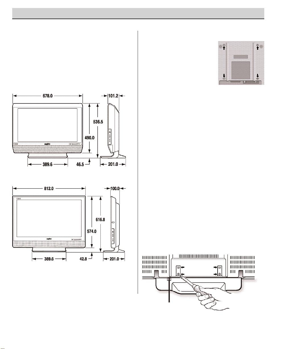
DETACHING THE DTV STAND
(OPTIONAL)
Tools Needed: Phillips screwdriver
Important Note: Place DTV face down on a
padded or cushioned surface to protect the
screen and finish.
1
Remove four (4) screws from the metal
bracket.
CAUTION: Hold the stand firmly as you
remove the last screw.
2
Carefully remove the DTV stand.
Model DP26746
Model DP32746
NOTE: All dimensions are in millimeters (mm).
WALL MOUNTING (OPTIONAL)
This LCD DTV is designed
so that it may be mounted
on a wall, if desired. Use
the threaded inserts on the
back of your DTV to secure
it using a wall mounting kit.
NOTE: Wall Mounting kit is
not supplied, check
with your local electronics store.
LCD Mounting screws measurements:
DP26746—M4 Diameter, Length—10mm
(minimum) to 20mm (maximum).
DP32746—M6 Diameter, Length—10mm
(minimum) to 20mm (maximum).
DTV Back View
PROTECTING THE LCD SCREEN
The screen is likely to be damaged if it is not
maintained properly. DO NOT use hard objects
such as hard cloth or paper. DO NOT use excessive pressure when cleaning the LCD screen;
excessive pressure can cause permanent
discoloration or dark spots.
Page 6
6
Need help?
Visit our Web site at www.sanyoctv.com or Call 1-800-877-5032
GETTING STARTED (REQUIRED INITIAL SETUP)
This LCD HDTV is capable of reproducing a
crystal clear digital picture and exceptional
sound.
The signal makes the difference!
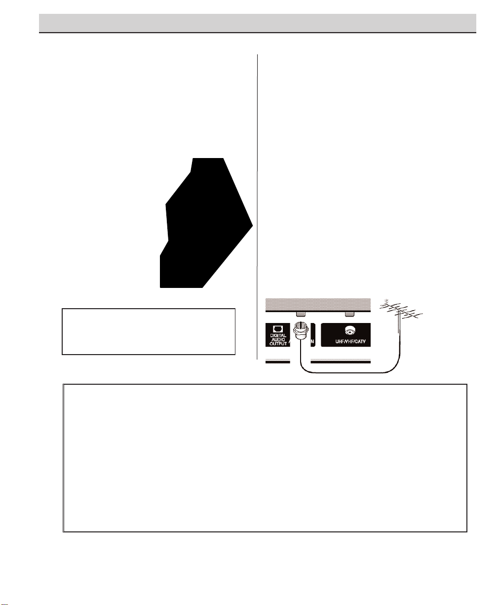
INITIAL SIGNAL CONNECTIONS
1
DIGITAL (DTV) RF ANTENNA
CONNECTION
•
Connect an RF antenna to the Digital
Antenna In terminal.
The digital tuner in this DTV receives HD signals
from an antenna. Digital signals from a Set-top
Box (STB) are received through the Component
In jacks.
This DTV can receive ANY resolution being
broadcast (HDTV, EDTV, or SDTV).
RF Antenna
DTV Back
Operational Tip for Monitor Use:
If the DTV is used as a monitor only, with a DVD
player or some other type of external equipment,
and no cable or antenna signal is available, the
following setup is necessary:
Your DTV is designed to automatically search for
available channels. Therefore, the initial start up
requires that you press the Channel (CH) key,
enabling the DTV to automatically go through the
channel search process before you can operate
the DTV.
After the initial channel search is completed, you
must press the Channel (CH) key again to
complete the channel search process. This may
take several minutes.
After the channel search process is complete (2
searches), you can press the INPUT key on the
remote control to use the DTV as a monitor.
INSTALLING BATTERIES IN THE
REMOTE CONTROL
Use 2 “AAA” batteries
(Not supplied)
.
Be sure batteries are installed correctly. Match
the “+” and “–” signs on the batteries with
marks inside the remote control.
NOTES:
– Do not mix old batteries with new
ones or mix different types of batteries together.
– Remove the batteries if the
remote control will not be
used for a month or more.
Weak batteries may leak
and cause damage. (Normal
battery life is roughly six
months.)
– Use two “AAA”
Alkaline batteries.
IMPORTANT NOTE: Spent or discharged batteries must be
recycled or disposed properly in compliance with all applicable laws. For detailed information, contact your local County
Solid Waste Authority.
Page 7

7
Need help?
Visit our Web site at www.sanyoctv.com or Call 1-800-877-5032
DTV will select the correct Antenna mode for the type
of Analog RF signal connected automatically.
Use “Analog Antenna Signal” in the Setup menu to
change the Antenna Mode.
If you move the DTV to a new location, press the
RESET key twice after connecting the signal and
turning on the DTV.
NOTES: If you do not have a VCR, connect signal directly
to the 75 ohm terminal (UHF/ VHF/CATV).
Don’t be fooled by the phrase “Available in
High-Definition.” The only resolution available
with any of these connections, regardless of the
original content, is standard analog (SDTV ).
RF
Antenna
DTV Back
VCR Back
2
ANALOG RF ANTENNA CONNECTION
•
Connect a Cable signal (with or without a cable box) or RF antenna to the
Analog RF input.
The analog tuner in this DTV receives Analog Antenna signals, Analog Cable
signals, or the RF output from a VCR or cable box.
CATV FRANCHISE NOTE: Cable companies, like public
utilities, are franchised by local government authorities. To
receive cable programs, even with equipment which is
capable of receiving cable channels, the consumer must
subscribe to the cable company’s service.
Analog Cable
Analog Satellite Receiver
DTV Back
VCR Back
DTV Back
VCR Back
OR
OR
(Continued on page 8.)
Page 8

8
Need help?
Visit our Web site at www.sanyoctv.com or Call 1-800-877-5032
If the DTV does not detect any digital or analog
channels, a message advising the viewer to check
the cables and antenna connections will appear. In
this case, you must press the
CHANNEL UP (CH
)
key again to repeat the channel search process.
If after two searches the DTV still fails to detect any
channels, the DTV will tune to analog channel 3.
These two channel searches are necessary even
if you plan to use the DTV only as a monitor.
If no analog or digital channels are found after
the second search, All Channel Search will default
to off-air analog channels 2 through 69 and digital
channel D3-1. Select analog channels using
the remote control keypad. See page 17, item
number 2.
4
ANALOG ANTENNA SIGNAL
(OPTIONAL)
To change the initial analog tuning system setup
(from antenna to cable or cable to antenna), use
the on-screen menu, see “Analog Antenna
Signal” on page 22.
3
ALL CHANNEL SEARCH
When the television is powered on for the first
time, it automatically checks for the presence of
an RF signal.
• Press the Power key
to turn on the DTV.
• Then press the Chan-
nel Up (CH ) key to
automatically search
for available channels:
Digital (ATSC) and
Analog (NTSC).
The All Channel Search
contains two processes
that are executed simultaneously for digital and
analog channels.
NOTES:
The on-screen message for digital search will appear
with a progress bar and percentile number displayed
across the bottom of the screen (to indicate activity)
as the search process continues.
Channel information found during the All Channel
Search is stored in Analog and Digital Channel Scan
Memory databases. After the All Channel Search is
completed, the DTV will tune to the lowest Digital
channel or lowest Analog channel if no digital channels are found.
Page 9

HDMI (High Definition Multimedia Inter-
face) Input, PAGES 11 and 12—Connect
digital video equipment to this jack. It takes
only one high bandwidth cable (not supplied) to communicate between audio/
video equipment and this DTV. This connection is compatible with DVI equipped AV
devices. (Separate audio connection and an
adapter are required for DVI device.)
Digital Audio Output, PAGE 14—Use an
Optical Audio cable to connect Digital Audio
Output to an advanced stereo home theater
system equipped with Dolby®Digital 5.1.
Digital Antenna Input, PAGE 5—Connect
an RF antenna to this jack.
Analog Antenna Input (UHF/VHF/CATV),
PAGE 5—Connect an RF antenna or Analog
cable system to this jack.
S-Video Input (VIDEO1), PAGE 15—To
enhance video detail use the S-Video jacks
instead of the Video jacks, if available on
your external equipment. (S-Video connection will override connection to the Video
input jack [VIDEO1]).
Audio/Video Input (VIDEO1), PAGE 15—
Connect analog video equipment here.
NOTE: S-Video connection overrides the
(VIDEO1) composite video connection.
Component Video Input (VIDEO2), PAGE
13—Connect digital video equipment to the
Y, Pb, Pr and Audio L / R jacks. These jacks
will automatically detect the type of signal
being received.
Component Video Input (VIDEO3), PAGE
13—Connect digital video equipment to the
Y, Pb, Pr and Audio L / R jacks. These jacks
will automatically detect the type of signal
being received.
Analog Audio Out (L/R) Jacks, PAGE 16—
Connect external audio equipment here.
9
Need help?
Visit our Web site at www.sanyoctv.com or Call 1-800-877-5032
SIDE AND BACK PANELS
Right Side Panel
(see items 8, 11, & 17
on pages 18 & 19)
Back Panel (Right)
Back Panel—Bottom View (Center)
Volume
– + keys
Channel
keys
Power
key
Back Panel (Center)
Page 10
10
Need help?
Visit our Web site at www.sanyoctv.com or Call 1-800-877-5032
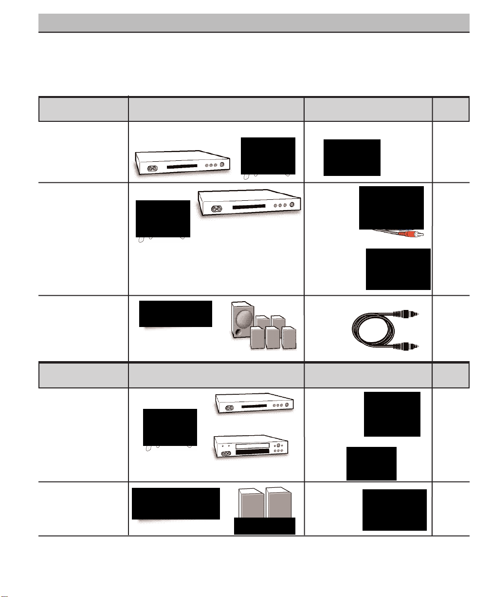
CHOOSE YOUR CONNECTION
Digital Signal Compatible External Cables Needed Go to
Connections Equipment
(Not Supplied)
Page
13
This DTV is designed to handle several different
connections making it compatible with Digital
and Analog devices.
In order to receive the best performance from
your DTV, choose your connection using this
chart; then go to the specified page for detailed
instructions.
COMPONENT
(Y, Pb, Pr) IN
Will accept HDTV,
EDTV, or SDTV
Video content.
(Requires separate
audio connections.)
Component
Video
Cable
[Green, Blue,
and, Red
connectors]
DIGITAL AUDIO OUT
(Only available when
received as part of a
Digital RF signal or
HDMI signal.)
Optical Digital
Cable
14
Audio Cable
[White and Red
connectors]
Multi-Channel
Receiver
Digital Set-Top Box or
DVD Player
HDMI
Will accept HDTV
(High Bandwidth
Video component
and Audio 5.1)
Digital Set-Top Box
or
DVD Player
19 Pin HDMI
11 OR
12
Video Game
Video Game
COMPOSITE VIDEO
OR
S-VIDEO IN
15
ANALOG AUDIO
OUT JACKS
16
S-Video
Cable
Analog Signal Compatible External Cables Needed Go to
Composite
Video Cable
[Yellow, White,
and Red
connectors]
DVD Player
VCR
Stereo Amplifier System
LEFT / RIGHT
ANALOG AUDIO IN
Audio Cable
[White and Red
connectors]
Video Game
Page 11
11
Need help?
Visit our Web site at www.sanyoctv.com or Call 1-800-877-5032
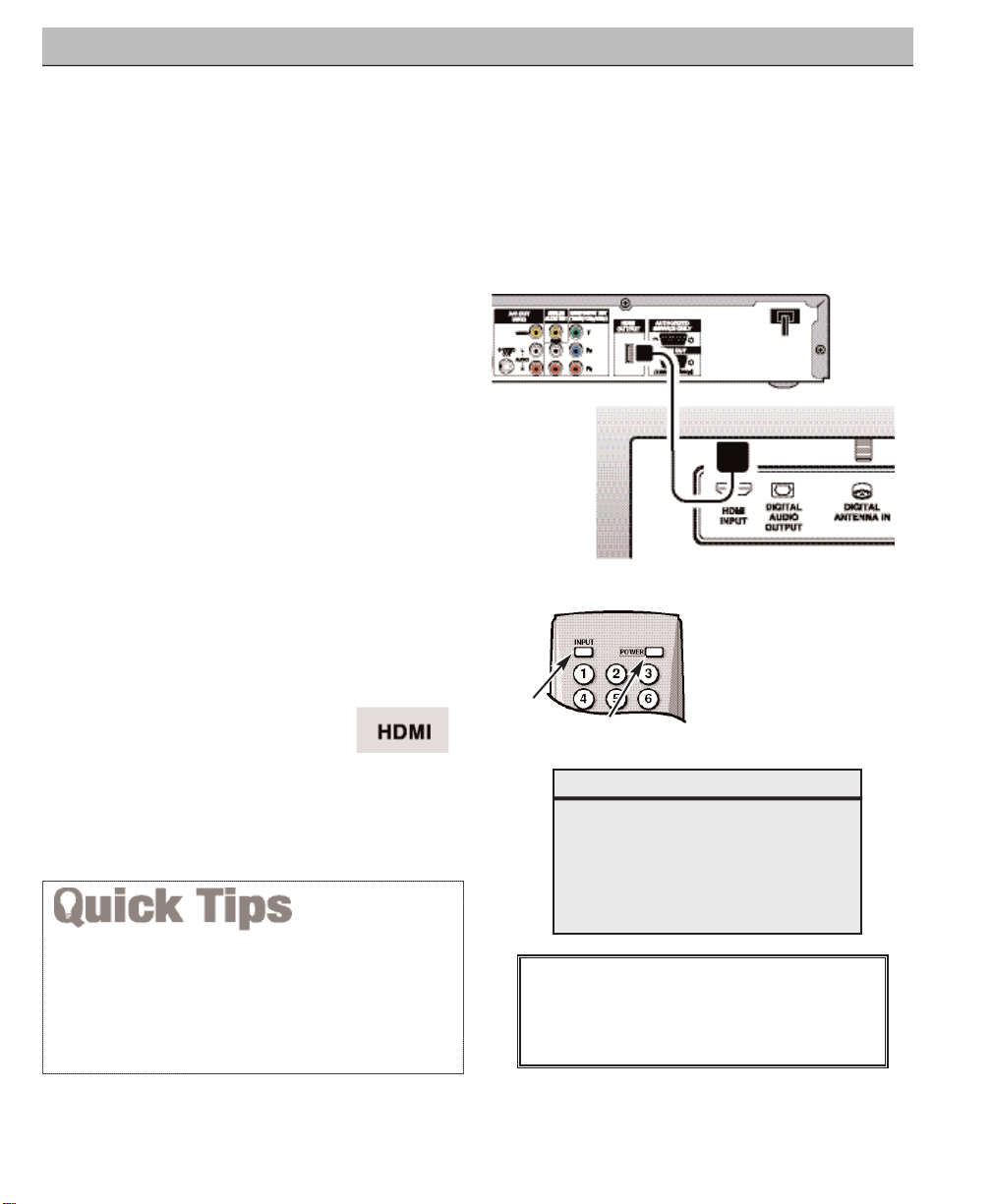
CONNECTING EXTERNAL EQUIPMENT TO HDMI (INCLUDES HDCP
COPY PROTECTION)
To avoid problems with some brands of external equipment, follow this procedure when
connecting cables and powering on your equipment.
What you will need for connections:
19 Pin HDMI Digital Cable – 1
(Make sure you check the pin configura-
tion of the cable plug-end*)
*Adapter may be required. Check with
your local electronics store.
DIGITAL AV CONNECTIONS
REMOTE CONTROL
SET-TOP BOX
(Can be a Digital Satellite Receiver,
DVD Player, or similar digital device.)
BACK VIEW
OF DTV
1
Switch off DTV and external equipment
before connecting cable.
(Cable is not
supplied.)
2
Connect the external equipment’s high
bandwidth HDMI Output to the DTV’s
HDMI Input.
3
The DTV must be turned on first, press
POWER. Then turn on your external
equipment.
4
Press INPUT to select
HDMI
to view a digital
program.
HDMI CABLE
(Gently insert
cable into
DTV HDMI
Input jack.)
4
2
3
If the television HDMI pin configuration is different from
the pin configuration on your set-top box, you will need to
use an Adapter.
Press the INPUT key after connecting cables to access the
AV Inputs. There is NO need to tune to a blank channel.
IMPORTANT NOTE FOR MONITOR USE:
If you did not connect an antenna, you must
run All Channel Search twice before you can
select the AV inputs.
This is the best option for picture and sound!
Using the HDMI connection,
which has high-definition content protection, provides you with uncompressed digital video and audio, Dolby®Digital 5.1 or PCM sound. This
connection requires only one cable.
As Real As It Gets!
Page 12

12
Need help?
Visit our Web site at www.sanyoctv.com or Call 1-800-877-5032
DIGITAL AV CONNECTIONS
Press the INPUT key after connecting cables to access the
AV Inputs. There is NO need to tune to a blank channel.
With a DVI connection, make sure you connect Audio out to
the DTV’s VIDEO3 Audio in.
Because the VIDEO3 audio jacks are used to receive the
audio from the DVI device, these video jacks cannot be used
when a DVI device is connected.
1
Switch off DTV and external equipment
before connecting cable.
(Cable is not
supplied.)
2
Connect the STB’s DVI Output to a “DVI to
HDMI Cable;” then connect the cable to
the DTV’s HDMI input.
NOTE: Check with your local electronics
store for a DVI to HDMI Cable that
matches your equipment and the
DTV.
3
Connect the STB’s Audio L/ R to the DTV’s
VIDEO3 Audio L/ R.
4
The DTV must be turned on first, press
POWER. Then turn on your external
equipment.
5
Press INPUT to select
HDMI
to view a
digital program.
BACK VIEW
OF DTV
2
3
SET-TOP BOX (Can be a Digital
Satellite Receiver, DVD Player, or
similar digital device.)
What you will need for
connections:
DVI to HDMI Cable – 1
Audio Cable – 1
REMOTE CONTROL
5
4
IMPORTANT NOTE FOR MONITOR USE:
If you did not connect an antenna, you must
run All Channel Search twice before you can
select the AV inputs.
CONNECTING STB WITH DVI OUTPUT TO HDMI INPUT
Page 13
13
Need help?
Visit our Web site at www.sanyoctv.com or Call 1-800-877-5032
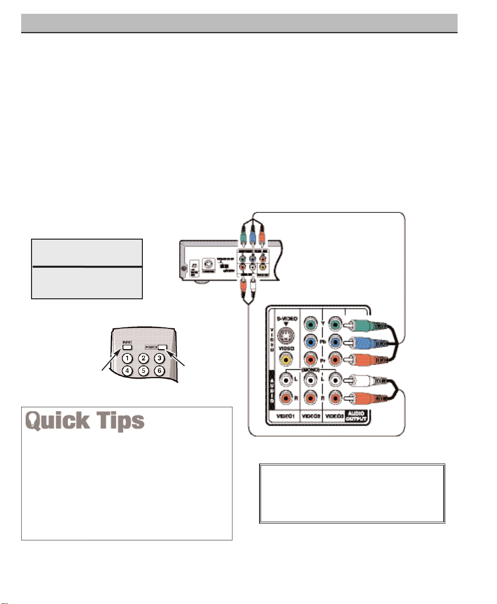
The Component Video jacks will accept any
video content.
Switch off DTV and external equipment before
connecting cables.
(Cables are not supplied.)
Follow these steps to easily connect your STB
or DVD Player to this DTV:
1
Connect DVD Player or similar digital
equipment’s Component Video Out to the
DTV’s Video (VIDEO3) jacks.
2
Connect DVD Player or similar digital
equipment’s Audio Out to the DTV’s
VIDEO3 Audio jacks.
3
Press POWER to turn on the DTV, then
turn on external equipment.
4
Press INPUT to select
Video 3
to view the
DVD program.
DVD PLAYER
(or similar digital
device such as a
Satellite Receiver.)
COMPONENT
JACKS
1
What you will need
for connections:
Component Video Cable – 1
Audio Cable – 1
DIGITAL AV CONNECTIONS
2
REMOTE CONTROL
4
3
USING COMPONENT JACKS TO CONNECT A DVD PLAYER OR
OTHER DIGITAL EQUIPMENT
VIDEO2 and VIDEO3 jacks have identical functions.
Compatible video devices can be connected to either set
of jacks.
Press the INPUT key after connecting the cables, to
select the
Video 2
or
Video 3
input signal. There is NO
need to tune to a blank channel.
“
No Signal” will appear randomly on the screen when
no signal is detected at the VIDEO2 or VIDEO3 inputs.
IMPORTANT NOTE FOR MONITOR USE:
If you did not connect an antenna, you must
run All Channel Search twice before you can
select the AV inputs.
DTV BACK
Page 14
14
Need help?
Visit our Web site at www.sanyoctv.com or Call 1-800-877-5032
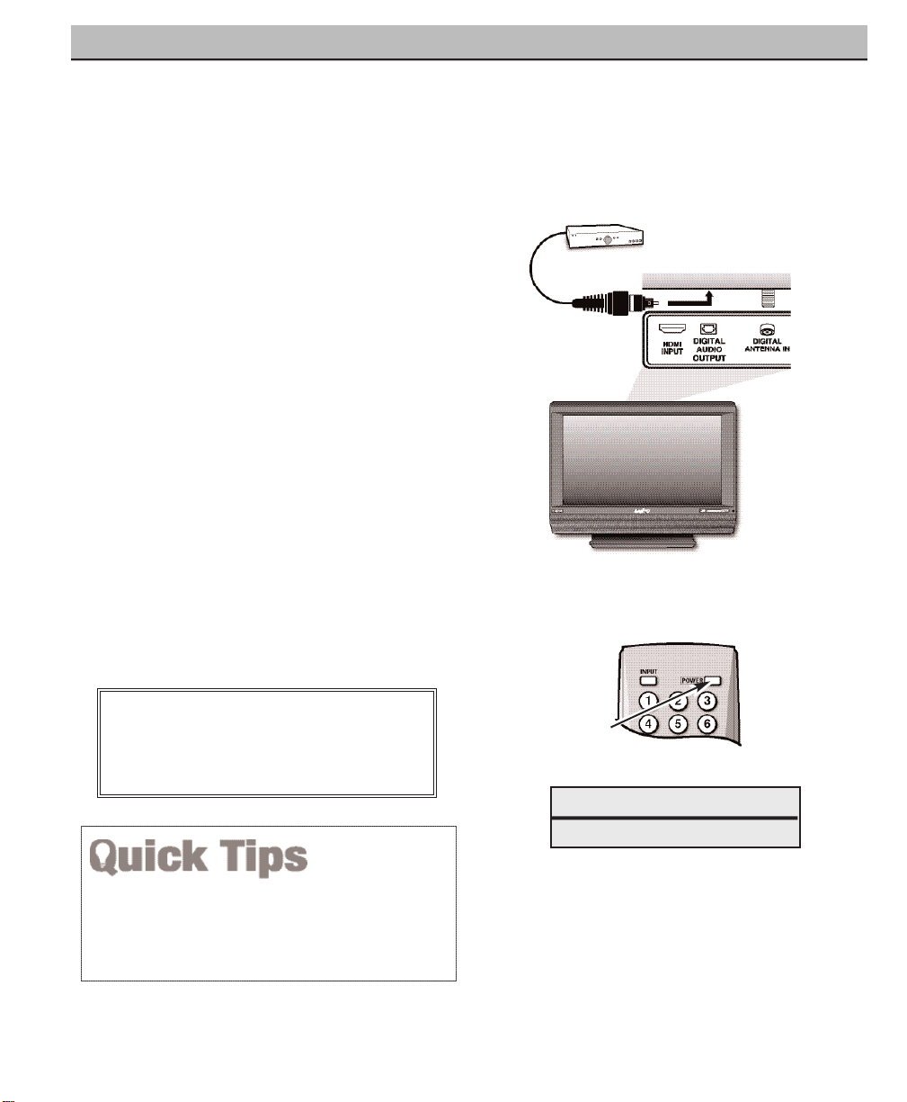
DIGITAL AV CONNECTIONS
Position your DTV at least 2 feet from stereo
speakers. The magnets in the speakers may affect the
picture quality.
Dolby®Digital Audio provides 5.1 channels of
surround sound (five full-range channels [5] and
one low-frequency effect channel [.1]). A fiber
optics cable is used to carry the 5.1 surround
sound (for low-noise signal transfer).
BACK
VIEW OF
DTV
OPTICAL
DIGITAL CABLE
1
Using a Fiber Optics cable, connect the
DTV’s Digital Audio Output to the Digital
Audio Input of a Multi-Channel Receiver.
(Fiber optics cable is not supplied.)
2
Press POWER to turn on the DTV, then turn
on external equipment.
NOTES:When making the connection, do not pinch or
kink the fiber optics cable.
Red light visible at the Digital Audio Output
does not necessarily indicate that Dolby
®
Digital 5.1 audio is available. Digital audio is
made up of light pulses that the human eye
cannot detect. Dolby
®
Digital 5.1 audio is
available at the Digital Audio Output only
when received as part of a Digital signal.
What you will need for connections:
Optical Cable – 1
MULTI-CHANNEL
RECEIVER
1
REMOTE CONTROL
2
IMPORTANT NOTE FOR MONITOR USE:
If you did not connect an antenna, you must
run All Channel Search twice before you can
select the AV inputs.
CONNECTING DIGITAL AUDIO OUT JACK TO A MULTI-CHANNEL
RECEIVER
Page 15
15
Need help?
Visit our Web site at www.sanyoctv.com or Call 1-800-877-5032
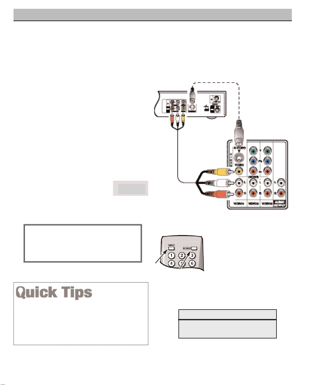
ANALOG AV CONNECTIONS
Switch off DTV and external equipment before
connecting cables.
(Cables are not supplied.)
BACK VIEW OF VCR
DTV AV
INPUT
JACKS
1
Connect VCR’s Audio Video Out to the
DTV’s VIDEO1 jacks.
NOTE: For Mono VCR (Single Audio Jack),
connect VCR Audio Out to DTV Audio (L)
Input.
22
Optional
Connect VCR’s S-Video Out to the HDTV's
S-Video In Jack.
NOTE: S-Video jack connections override
VIDEO1 Video jack connection.
3
Press POWER to turn on the DTV, then turn
on external equipment.
4
Press INPUT to select
Video 1
to view the VCR
program.
What you will need for connections:
Audio Video Cable – 1
S-Video Cable – 1
S-VIDEO
JACK
1
REMOTE CONTROL
4
3
22
Press the INPUT key after connecting cables to access
the VIDEO1 input. There is NO need to tune to a blank
channel.
“No Signal” will appear randomly on the screen when
no signal is detected at the VIDEO1 video jack.
IMPORTANT NOTE FOR MONITOR USE:
If you did not connect an antenna, you must
run All Channel Search twice before you can
select the AV inputs.
NOTES: Don’t be fooled by the
phrase “Available in
High-Definition.” Com-
posite jacks offer only
480i (SDTV) resolution.
To view available HighDefinition (HD) programs, you must connect your HD equipment
to the Component or
HDMI jacks.
Video 1
USING THE ANALOG VIDEO JACKS TO CONNECT A VCR
(OR OTHER ANALOG DEVICE)
Page 16
16
Need help?
Visit our Web site at www.sanyoctv.com or Call 1-800-877-5032
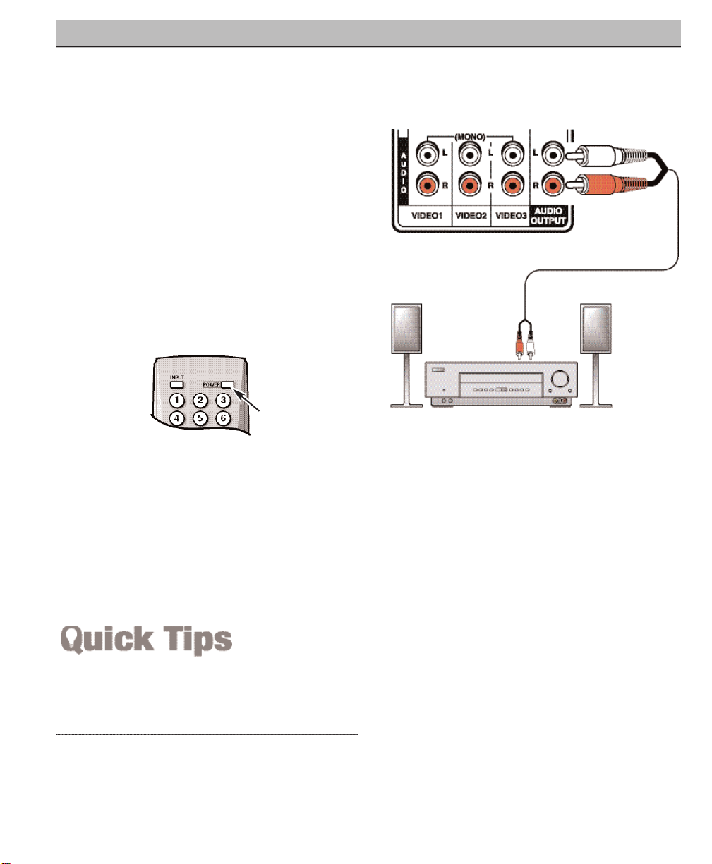
ANALOG AV CONNECTIONS
Switch off DTV and external equipment
before connecting cables.
(Cables are not
supplied.)
STEREO AMPLIFIER
BACK VIEW
OF DTV
1
Connect the DTV Audio Out (R/L) to the
Stereo Amplifier In (R/L).
2
Press POWER to turn on the DTV, then
turn on external equipment.
NOTE: Do not connect external speakers
directly to the DTV.
1
Position your DTV at least 2 feet from stereo speakers.
The magnets in the speakers may affect the picture
quality.
REMOTE CONTROL
2
CONNECTING ANALOG AUDIO OUT JACKS TO A STEREO AMPLIFIER
Page 17
17
Need help?
Visit our Web site at www.sanyoctv.com or Call 1-800-877-5032
USING THE REMOTE CONTROL
PRECAUTIONS
To ensure safe operation, please observe the following
precautions:
Replace both batteries at the same time. Do not use a new
battery with a used battery.
Risk of explosion, if battery is replaced by an incorrect type.
Do not expose the Remote Control Unit to moisture or heat.
REMOTE CONTROL KEYS
Input Key—Press to change the input signal
source as follows: Analog RF Digital RF
Video 1 Video 2 Video 3 HDMI
Analog RF.
Number Keys—Two keys must be pressed
to select a direct channel.
Example:
Press 0
then 6 to select channel 6.
For Analog Cable channels above 100,
press and hold the 1 key until C1– –
appears, then press the other two
numbers.
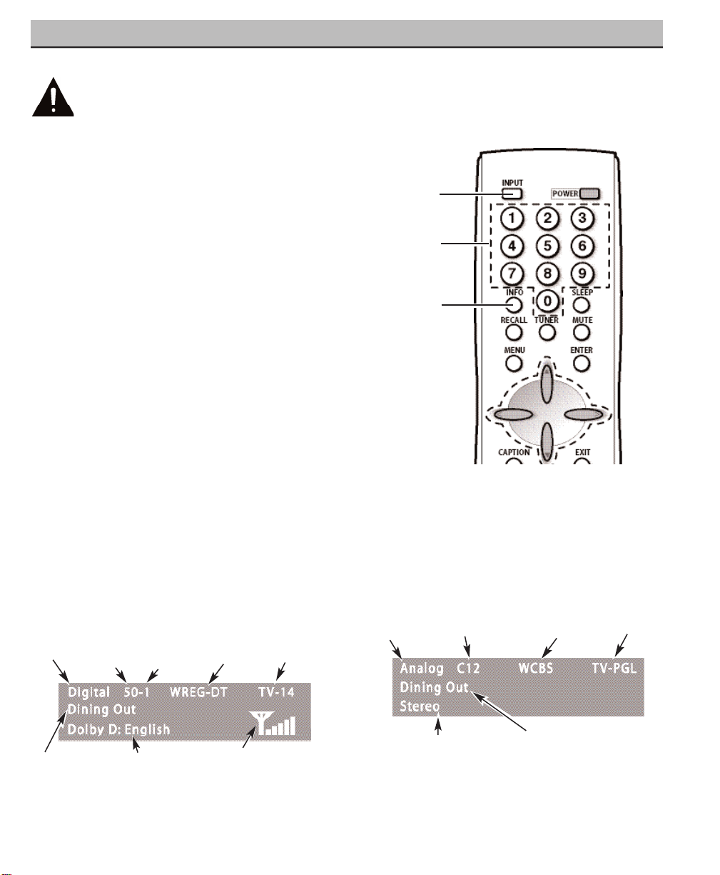
Info Key—Press to display the Digital and
Analog Full Banner information (press again
to remove the display).
Digital Full Banner display—
Contains a twopart Channel Number (Major and Minor), and
Tuner ID. If available the following is also
included: Station ID, V-Chip Program Rating,
Program Title, Audio Info, and Signal Strength.
Analog Full Banner display—
Contains the
Channel Number (analog antenna/cable),
Tuner ID, Station ID (if available), Program
Title (if available), V-Chip Program Rating, and
Audio Info.
Program Rating
Program Title
Tuner ID
Audio Info
Program Rating
Station ID
Program Title
Point toward
DTV
Channel
Major Minor
Signal Strength
Channel No.
Tuner ID
(Continued on page 18.)
Audio Info
Station ID
Page 18

18
Need help?
Visit our Web site at www.sanyoctv.com or Call 1-800-877-5032
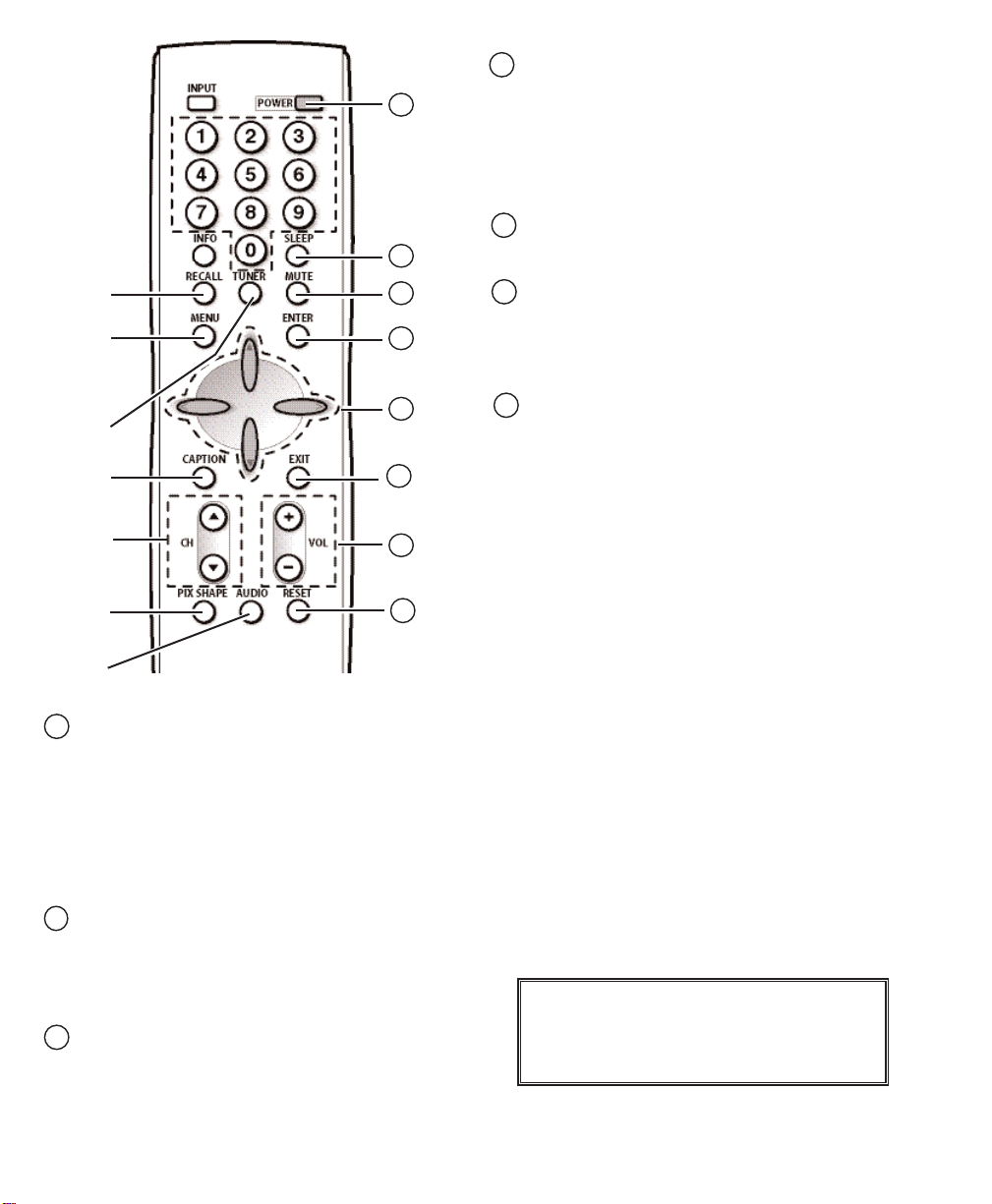
Recall Key—Select the first channel you
want to watch; then select another channel
using the NUMBER keys. Press RECALL to
switch between the channels.
NOTE: The RECALL key cannot toggle between a
Digital channel and an Analog channel.
See TUNER (#6) key description.
Menu key—Press this key to display the onscreen menu.
Tuner Key—Use this key to toggle from one
tuning system to another, digital channels
and analog channels.
NOTE: The TUNER key is inactive when an
external input is selected (Video 1,
Video 2, Video 3, or HDMI).
Caption Key—Press to select analog or
digital captioning. The Analog Caption
modes are: CC1 ~ CC4, Quikcap, and OFF.
The Digital Caption modes are: Digital
CC1 ~ CC6, Quikcap, and OFF.
Channel Scanning ((CH ) Keys—Press
(up) (down) keys to tune to the next
higher or lower channel in the Channel Scan
Memory list. The scanning loop includes
analog channels, digital channels, and all AV
inputs.
Pix Shape Key—Use this key to change the
video display format. Available options
depend on signal received and the broadcast’s aspect ratio. They may include:
PIX1
,
PIX2, PIX3
, and
PIX4
. See simulated DTV
images below.
Audio Key—Press to select the desired
audio mode (if available): DIGITAL: Main,
Sub1, Sub2, Sub3, etc.; ANALOG: Stereo,
Mono, SAP.
Power Key—Press to turn DTV on or off.
REMOTE CONTROL KEYS (CONTINUED)
11
PIX1
Gray colored borders
appear at the sides, of
the screen.
Note: 4:3 image without
distortion on a 16:9
screen.
PIX3
Enlarges a Pix2 image
vertically (some of the
image may be cropped
off).
PIX4
Stretches the Pix3
image horizontally (portions of the sides
and/or top and bottom
may be cropped off).
PIX2
A 16:9 image fills the
screen normally. A 4:3
images is stretched horizontally and may appear distorted.
Page 19
19
Need help?
Visit our Web site at www.sanyoctv.com or Call 1-800-877-5032
Sleep Key—Press this key, then press the
“0” key to set the Sleep Timer. The desired
time can be set from 30 minutes up to 3
hours in 30 minutes increments. Sleep Timer
will switch off the DTV automatically.
NOTE: The Sleep Timer cancels when the DTV is
turned off or if a power failure occurs.
Mute Key—Press once to minimize the
volume. Press again to restore.
NOTE: This key will not mute sound from the
audio out jacks
.
Enter Key—Press this key to select an option
from the menu system, when required.
. Cursor (up) (down) keys—Press these
keys to move the cursor up and down within
the menu.
Cursor
< (left) > (right) keys—Press these
keys to move the cursor left and right within
the menu.
Exit Key—Press this key to exit from the
menu system.
Volume (VOL – +) Keys—Press the – + keys
to adjust volume. The screen displays a left or
right red arrow that blinks as many times as
you press the Vol – + keys.
Reset Key—Press twice to restore factory
settings. The DTV will automatically start
Channel Search and clear all customized
settings.
NOTE: The Reset Function includes a channel
search. Current Digital and Analog channel
databases will be deleted and new ones
created by the Channel Search process. To
receive Digital Cable channels, see page
21 for Digital Cable Search.
These features will reset to factory defaults:
• Picture/ Sound Adjustments: Color, Tint,
Contrast, Brightness, Sharpness, and Tone
• Channel Memory—Digital /Analog channel
databases will be replaced
• Analog Audio to Stereo
• Captioning to OFF
• V-Guide to OFF
• Menu Language to English
• Sleep Timer to OFF (if previously set)
• Any Video mode to DTV mode
If desired, personal settings can be made
again using the menu options.
12
13
14
11
16
15
17
18
12
13
14
16
15
17
18
IMPORTANT NOTE FOR MONITOR USE:
If you did not connect an antenna, you must
run All Channel Search twice before you can
select the AV inputs.
Page 20

20
Need help?
Visit our Web site at www.sanyoctv.com or Call 1-800-877-5032
DTV ADJUSTMENT AND SETUP
The on-screen menu system provides the viewer
with easy access to adjustments and settings.
Just use the MENU, CURSOR, ENTER, and EXIT
keys on the remote control and follow the onscreen instructions. Generally, you will use the
CURSOR keys to select a menu item and the
CURSOR < > keys to make an adjustment. The
ENTER key confirms a setting. Press the EXIT key
to return to normal DTV viewing.
IMPORTANT FACTS:
Some Menu options are specific to Digital and
Analog signals and will vary accordingly.
Also, some options are not available in combination.
Unavailable options will appear “grayed-out” in the
menu. For example, Analog Antenna Signal is not
available when tuned to a Digital Channel.
MENU NAVIGATION MAP
MAIN MENU SUB MENUS
HOW TO OPERATE THE MENU
All Channel Search
Digital Cable Search
Digital Add-on Search
No
Yes
No
Yes
No
Yes
Analog Antenna Signal
Cable
VHF/UHF
Channel Scan Memory
Delete?
Add?
Digital Caption
Font Size
Font Style
Background Color
Foreground Color
Background Opacity
Foreground Opacity
V-Guide
Off
On
Menu Language
English
Español
Français
Color
Tint
Contrast
Brightness
Sharpness
Tone
1
Press the MENU key to display the Main
menu.
2
Use the CURSOR keys to highlight
(green)
All Channel Search.
Press ENTER.
3
Use the CURSOR key to select
Ye s
.
Press ENTER.
Use All Channel Search to replace existing Digital
and Analog Channel databases, such as, if you
move to another city.
NOTES: During All Channel Search, current Digital
and Analog channel databases are deleted
and new ones created. To receive Digital
Cable channels, if available, you must
perform a Digital Cable Search.
To add new digital channels to the existing
database, use Digital Add-on Search, see
page 22.
ALL CHANNEL SEARCH
Picture/Sound
Auto
Manual
Adjust
Page 21

21
Need help?
Visit our Web site at www.sanyoctv.com or Call 1-800-877-5032
IMPORTANT FACT: This DTV maintains only one data-
base of digital channels. Therefore, when you search
for ClearQAM digital cable channels, the database of
antenna digital channels will be deleted. You will only
be able to receive those ClearQAM channels your
cable company provides.
Cable companies rearrange
virtual channels as programming changes, which may
cause the program you are watching to move to another channel. This message will appear on the screen
briefly to notify you of a change. You will have to relocate the program you were watching by scanning
through the channels.
To restore the antenna digital channel database,
reconnect the antenna and use the menu system to
perform an All Channel Search.
DIGITAL CABLE SEARCH (OPTIONAL)
This DTV can receive unscrambled (ClearQAM)
digital cable channels, when available. However,
not all cable companies provide ClearQAM
digital channels.
Searching for digital cable channels will take
about 10 minutes, please be patient.
1
Connect a Digital Cable
signal directly to the DTV
Digital Antenna In Terminal.
2
Press the TUNER key to
select the Digital Tuner.
3
Press the MENU key to display the Main
menu.
4
Use the CURSOR keys to highlight
(green)
Digital Cable Search
. Press ENTER.
5
Use the CURSOR key to select
Ye s
.
Press ENTER.
NOTE: After Channel Search is complete, the DTV
will tune to the lowest Digital Cable channel
(or lowest Analog channel if no Digital Cable
channel is found).
Page 22

22
Need help?
Visit our Web site at www.sanyoctv.com or Call 1-800-877-5032
DIGITAL ADD-ON SEARCH
Use this feature to add new channels to the
digital antenna channel database. Also, use this
feature to add channels when broadcast towers
are in multiple directions from your location.
1
Press the TUNER key to select the Digital
Tuner.
2
Press the MENU key to display the Main
menu.
3
Use the CURSOR keys to highlight
(green)
Digital Add-On Search
. Press
ENTER.
4
Use the CURSOR key to select
Ye s
.
Press ENTER.
NOTES: Turn your Antenna and repeat these steps for
each direction in which there are transmitting
towers.
Go to www.antennaweb.org and type in
your zip code to obtain specific tower and
antenna information.
NOTE: If the DTV is switched off by pressing the
POWER key or unplugging the AC during
Digital Add-On Search, all channel information detected before the power loss occurred
will be saved.
ANALOG ANTENNA SIGNAL
Use this feature to switch between analog off-air
channels and analog cable channels.
1
Press the TUNER key to select analog
channels.
2
Press the MENU key to display the Main
menu.
3
Use the CURSOR keys to highlight
(green)
Analog Antenna Signal
. Press
ENTER.
4
Use the CURSOR keys to choose
Cable
or
VHF/ UHF
. Press ENTER.
5
Press the EXIT key to return to normal DTV
viewing.
Page 23

23
Need help?
Visit our Web site at www.sanyoctv.com or Call 1-800-877-5032
TO DELETE CHANNELS FROM THE
CHANNEL SCAN MEMORY
3
Use the CHANNEL (CH ) keys or
numerical keys to select desired channel.
HINT: Press the TUNER key to switch
between Digital and Analog Channel Scan
memories.
4
Press the ENTER key to delete the channel.
The display will change to “deleted.”
NOTES: “Delete?” will appear below the channel
number if the selected channel is already in
the Channel Scan Memory.
Use the Number keys to tune to active channels not in the Channel Scan Memory list.
CHANNEL SCAN MEMORY
Channel Scan Memory is a list of active channels
that you can scan through using the CHANNEL
SCAN CH (up) CH (down) keys. This list can
be customized by deleting and/or adding channels.
1
Press the MENU key to display the Main
menu.
2
Use the CURSOR keys to highlight
(green)
Channel Scan Memory
. Press
ENTER.
When a digital channel is deleted, all of that channel’s
sub-channels are deleted as well.
Only previously deleted digital channels can be added
back to the Channel Scan Memory.
If one digital sub-channel is added back to the Channel
Scan Memory all of that channel’s sub-channels will be
added back.
If the last remaining digital channel is deleted, the entire
previous Channel Scan Memory list will be restored
automatically.
If the last remaining analog channel is deleted (cable or
off-air channel), ALL analog channels (cable or off-air)
will be restored automatically, regardless of the previous
Analog Channel Scan Memory list.
TO ADD A CHANNEL TO THE CHANNEL
SCAN MEMORY
3
Use the numerical keys 0 ~ 9 to select
desired channel number. “Add?” will appear
below the channel number. HINT: Press the
TUNER key to switch between Digital and
Analog Channel Scan memories.
4
Press the ENTER key to add the channel.
The display will change to “Added.”
When you have finished adding and/or deleting
channels, press the EXIT key to return to normal
DTV viewing.
Page 24

Closed-Captioning is hidden textual information
transmitted along with the picture and sound.
Turning Captioning ON causes the DTV to open
these captions and superimpose them on the
screen. Because different types of closedcaptions can be transmitted with the picture
and sound, separate captioning modes are provided. The captioning modes recognized by this
model are: Analog EIA-608B and Digital EIA708B. Local broadcasters decide which caption
signals to transmit.
CHANGING THE LOOK OF DIGITAL
CAPTIONS
This
Font Size, Font Style, Background Color,
Foreground Color, Background Opacity
, and
Foreground Opacity
of Digital Captions can be
changed.
NOTES: If Background Opacity is set to transparent,
captions may be difficult to see.
Only true
EIA 708B Digital Closed-Captions are
affected by all of these settings.
Analog captions generally will not respond to
these adjustments, however, upconverted
analog captions may respond to some
options.
1
Press the TUNER key to select the Digital
Tuner.
2
Press the MENU key to display the Main
menu.
3
Use the CURSOR keys to highlight
(green)
Digital Caption
. Press ENTER.
4
Use the CURSOR keys to highlight
(green) an option. Press ENTER.
5
Use the CURSOR or < > keys to
select the desired effect.
6
When you have finished making adjustments, press the EXIT key to return to
normal TV viewing.
TO VIEW CAPTIONS
1
Press the CAPTION key to select caption
modes.
Digital modes
: Digital CC1 through Digital
CC6, QuikCap, and Off.
Analog modes
: CC1 through CC4,
QuikCap, and Off.
QUIKCAP OPERATION
QuikCap turns captioning on and off with the
Mute
function. Press the MUTE key on the
remote control to block the TV sound; the captions display automatically, if available. Press the
MUTE key again to restore the sound. Captions
will disappear.
DIGITAL CAPTION
Analog Caption
Digital Caption
24
Need help?
Visit our Web site at www.sanyoctv.com or Call 1-800-877-5032
Page 25

25
Need help?
Visit our Web site at www.sanyoctv.com or Call 1-800-877-5032
V-GUIDE (PARENTAL CONTROL)
NOTE:THIS FEATURE IS DESIGNED TO COMPLY WITH
THE UNITED STATES OF AMERICA’S FCC V-CHIP REGULATIONS. THEREFORE, IT MAY NOT FUNCTION
WITH BROADCASTS THAT ORIGINATE IN OTHER
COUNTRIES.
This Sanyo television is equipped with an electronic V-Chip to interpret MPAA (Motion Picture
Association of America) and DTV Parental Guidelines rating codes. When these codes are
detected, the DTV will automatically display or
block the program, depending upon choices you
make when setting up the V-Guide system.
Content ratings are represented by the initials: FV
(fantasy violence), L (adult language), S (sexual
situations), V (violence), and D (suggestive dialog).
A rating icon will generally appear at the beginning of a program, see chart on page 26.
This television can be set to block programs with
content you deem as inappropriate for your
children to view.
TO BLOCK MPAA MOVIE OR TV PROGRAM
1
Press the MENU key to display the Main
menu.
2
Use the CURSOR keys to highlight
(green)
V-Guide.
Press ENTER.
3
Use the CURSOR keys to select ON.
Press ENTER.
TO SETUP V-GUIDE RATINGS
4
Use the CURSOR to select
Adjust
. Press
ENTER.
5
Press CURSOR and < > keys to select
MPAA, TV Rating, or Content Ratings. (A
green square will appear beside the
selected item.)
6
Press the ENTER key to Block or Unblock
selected option. A lock ( ) will appear
beside the selected rating option indicating
it is blocked.
V-GUIDE RATINGS—AT-A-GLANCE
MPAA (Movie) RATING
BLOCKED RATINGS
(Lock symbol)
7
When you have finished making adjustments, press the EXIT key to return to
normal DTV viewing.
CONTENT
RATING
(Continued on next page.)
IMPORTANT FACT: The DTV will automatically block
ratings above or unblock ratings below a selection.
For example, if you block DTV rating DTV-PG, ratings
DTV-14 and DTV-MA will be blocked automatically; or
if you block Movie rating PG-13, ratings R, NC17, and
X will be blocked automatically.
Blocking TVY7 does not block higher ratings.
TV RATING
Page 26

TO TEMPORARILY UNBLOCK MPAA MOVIE
OR TV PROGRAM
1
Press the MENU key to display the Main
menu.
2
Use the CURSOR keys to highlight
(green)
V-Guide.
Press ENTER.
3
Use the CURSOR keys to select
OFF
. Press ENTER.
This will temporarily set V-Guide to
OFF
. When
V-Guide is reset to ON (follow steps 1~2), the
DTV will automatically revert to previously
selected block ratings.
TO UNBLOCK ALL MPAA MOVIE OR ALL TV
RATING
1
Press the MENU key to display the Main
menu.
2
Use the CURSOR keys to highlight
(green)
V-Guide
. Press ENTER.
3
Press ENTER to select
Adjust
.
4
Highlight the “Allow All” option using the
CURSOR and < > keys, if needed.
Press ENTER.
26
Need help?
Visit our Web site at www.sanyoctv.com or Call 1-800-877-5032
V-GUIDE (PARENTAL CONTROL) CONTINUED
You can block portions of a DTV rating by choosing one
or more of the Content ratings (D, L, S, and V). By blocking just the L and S content ratings of DTV-14,
for
example,
DTV-14 rated programs with a D and/or V
content rating could still be viewed.
V-Guide limits on programming received via the Analog
antenna input, Digital antenna input, VIDEO1 Video input,
and any 480i signals received through the VIDEO2 or
VIDEO3 jacks are controlled by this DTV.
V-Guide limits on digital programming received through
the Component jacks (VIDEO2 or VIDEO3) are controlled
by the external devices connected to those jacks (such as
a DVD Player or Satellite Receiver). Refer to your external
device’s owner’s manual for instructions on setting
V-Guide limits.
Networks and local stations may or may not include the
content ratings portion of the DTV Parental Guidelines.
ALL CHILDREN—Program is designed to be appropriate for children ages 2-6.
DIRECTED TO OLDER CHILDREN—Program is
designed for children 7 and above. Material may include mild fantasy violence (FV) or comedic violence.
GENERAL AUDIENCE—Program suitable for all
ages. Contain little or no violence, no strong language or sexual dialogue or situations.
PARENTAL GUIDANCE SUGGESTED—Program
contains material that may be unsuitable for younger
children. Material contains one or more for the following: moderate violence (V), some sexual
situations (S), infrequent coarse language (L), or
some suggestive dialogue (D).
PARENTS STRONGLY CAUTIONED—Some material
is unsuitable for children under 14 years of age.
Parents are strongly urged to use caution against
letting children under age 14 watch unattended.
Material contains intense violence (V), intense
sexual situations (S), strong coarse language (L), or
intensely suggestive dialogue (D).
MATURE AUDIENCE ONLY—Program is designed to
be viewed by adults and therefore may be unsuitable
for children under 17 years of age.
TV RATINGS (AGE/CONTENT-BASED)
G GENERAL AUDIENCES—All ages admitted.
PG PARENTAL GUIDANCE SUGGESTED—Some
material may not be suitable for children.
PG-13 PARENTAL GUIDANCE CAUTIONED—Some
material may be inappropriate for children
under 13.
R RESTRICTED—Under 17 requires accompanying
parent or adult guardian
NC-17 NO ONE 17 AND UNDER ADMITTED
MPAA MOVIE RATINGS (AGE-BASED)
Page 27

1
Press the MENU key to display the Main
menu.
2
Use the CURSOR keys to highlight
(green)
Picture/ Sound
. Press ENTER.
3
Use the CURSOR keys to highlight
(green)
Auto
(factory preset settings) or
Manual
. Press ENTER.
MANUAL ADJUSTMENTS
4
Use the CURSOR keys to select the
option you want to adjust.
5
Then use the CURSOR < >keys to make an
adjustment.
6
When you have finished making adjustments, press the EXIT key to return to
normal D T V viewing.
PICTURE/SOUND ADJUSTMENT
27
Need help?
Visit our Web site at www.sanyoctv.com or Call 1-800-877-5032
MENU LANGUAGE
1
Press the MENU key to display the Main
menu.
2
Use the CURSOR keys to highlight
(green)
Menu Language
. Press ENTER.
3
Use the CURSOR keys to select
English,
Español, or Français.
4
Press the EXIT key to return to normal DTV
viewing.
Page 28

Problem Check these Conditions Try these Solutions Page No.
DTV turns off
automatically.
The sleep timer may have been set.
Press POWER key.
19
No picture, sound
(Digital Picture).
Check antenna/external connections.
May be station trouble, NO signal
broadcast.
MUTE function may be on.
Adjust antenna.
Try a different channel.
Press RESET key to restart channel
search.
Adjust Volume.
6, 19
No Captioning.
Check if station is broadcasting a
Closed-Caption signal. Select another
channel.
Press CAPTION key to select
Captioning.
24
Cannot customize
Caption.
Digital Caption signal not broadcast.
Press CAPTION key to select Analog
captioning.
24
Cannot display
picture on a full
screen.
Check Aspect Ratio of broadcast.
Press PIX SHAPE key to change
setting.
18
Pixilation of Digital
image.
Press INFO key and check the signal
strength.
Turn antenna, install signal booster.
Install outdoor Digital antenna.
6, 17
Poor Picture/
Sound.
Check if program is in color.
Check antenna/external connections.
Color or Tint misadjusted.
May be station trouble.
MUTE function may be on.
Try a different channel.
Adjust antenna.
Press RESET key to restart channel
search.
Adjust Volume.
7, 19, 27
“No Signal”
message appears
on the screen.
Check Audio/ Video connections.
Check external equipment connections.
Check external equipment setting.
Press INPUT key.
Switch on external equipment.
Set external equipment output connections to match input connections.
11 ~ 16
Because of the Quality we build into our
product, very few problems are actual DTV
defects. Most problems only involve simple
hookup or setup changes that can be solved by
the customer. Please check the chart below and
try the solutions listed for your problem. If the
problem still persists, before returning your
DTV, please visit our website at www.sanyoctv.com or call us toll free at 1.800.877.5032.
We can Help!
HELPFUL HINTS (Problems/Solutions)
28
Need help?
Visit our Web site at www.sanyoctv.com or Call 1-800-877-5032
Page 29

Problem Check these Conditions Try these Solutions Page No.
No DTV Stereo or
SAP sound.
Check if station is broadcasting a true
MTS stereo signal or a SAP signal.
Press AUDIO key.
18
No UHF, VHF
Channels OK.
Cable Channel indicator C should
not
appear next to the channel number.
Switch Analog antenna signal to
VHF/UHF.
22
Cannot select or
scan some
channels.
Channel may be removed from
memory.
Check antenna connections.
No digital signal being broadcast.
Signals are weak.
V-Guide is set to block programming.
Select Channel Scan Memory and manually add channels or start CH. (channel)
search.
Turn Antenna or install signal booster.
Set V-Guide to “None” or press the
RESET key to clear all settings and
restart channel search.
23
25 ~ 26
19
No Cable channels
above number 13.
Cable Channel Indicator C should
appear next to channel number.
Switch Analog Antenna signal to Cable.
22
Remote Control
will not work DTV.
Check batteries
Make sure DTV is plugged in.
Replace batteries two “AAA.”
Aim remote control at front of DTV.
6,17~19
Cabinet makes
popping sound.
This is a normal condition during
warm-up and cool down of the plastic
cabinet parts.
29
Need help?
Visit our Web site at www.sanyoctv.com or Call 1-800-877-5032
This symbol on the nameplate means the product is Listed by Underwriters’
Laboratories Inc. It is designed and manufactured to meet rigid U.L. safety
standards against risk of fire, casualty and electrical hazards.
CARE AND CLEANING
CLEANING THE CABINET
The surface of the cabinet can be damaged if not
properly maintained. Many common household
aerosol sprays, cleaning agents, solvents, and
polishes will cause permanent damage to the
fine surface.
1. Unplug the power cord before cleaning the
television.
2..Gently wipe the screen and cabinet with a
DRY SOFT CLOTH.
The screen is likely to be damaged if it is not
maintained properly. DO NOT use hard objects
such as hard cloth or paper. DO NOT use
excessive pressure when cleaning the LCD
screen; excessive pressure can cause permanent discoloration or dark spots.
NOTE: Never spray liquids on
the screen because they can
run down and enter the
cabinet. This may cause component failure not covered
under Warranty.
Page 30

IMPORTADOR:
COMERCIALIZADORA MEXICO
AMERICANA, S.DE R.L. DE C.V.
AV. NEXTENGO N
o
78
COL. SANTA CRUZ ACAYUCAN
DEL. AZCAPOTZALCO, MÉXICO, D.F. C.P. 02770
RFC: CMA9109119L0
GUARANTEE
THE APPARATUS THAT YOU HAVE ACQUIRED HAS AONE YEAR GUARANTEE FOR MANUFACTURING DEFECTS AND
A ONE YEAR SERVICE WARRANTY FROM THE DATE OF PURCHASE GRANTED BY:
COMERCIALIZADORA MEXICO-AMERICANA, S. DE R.L. DE C.V.
UNDER THE FOLLOWING CONDITIONS:
1. TO MAKE THE GUARANTEE EFFECTIVE, SIMPLY SHOW THIS POLICYFILLED OUT BY THE STORE OR SUPPLIER
UNIT OR THIS SALES INVOICE, WITH THE APPARATUS IN ANY OF THE SERVICE CENTERS INDICATED ON THIS
GUARANTEE.
2. IF THE FAULT IS ATTRIBUTED TO A MANUFACTURING DEFECT, THE APPARATUS WILL BE REPLACED OR YOUR
MONEY REFUNDED. DURING THE 30 DAYS SUBSEQUENT TO THE PURCHASE THE GUARANTEE WILL BE VALID
AT THE STORE WERE THE APPARATUS WAS PURCHASED, PRESENTING THE ABOVE DOCUMENTS.
3. REPAIR TIME WILL NEVER BE MORE THAN 30 DAYS. IF THIS TIME HAS ELAPSED, AND THE PRODUCT ISN’T
REPAIRED, COMERCIALIZADORA MEXICO AMERICANA, S. DE R.L. DE C.V. WILL PROCEED TO EFFECTUATE
THE EXCHANGE FOR AN EQUIVALENT APPARATUS OR THE RETURN OF THE BUYING-SALE COST
RESPECTIVELY.
4. THIS GUARANTEE WILL COVER ITS TOTALITY OF PIECES, COMPONENTS AND SERVICE REPAIR OF PRODUCT,
AND THE RESPECTIVE COST OF TRANSPORTATION.
THIS GUARANTEE WILL
BE NULL AND VOID IN THE FOLLOWING CIRCUMSTANCES:
*
WHEN PRODUCT HAS BEEN USED IN A DIFFERENT CONDITION THAN ITS NORMAL USE.
*
WHEN PRODUCT HASN’T BEEN OPERATING CORRECTLY ACCORDING TO THE INSTRUCTIONS IN THIS MANUAL.
*
WHEN PRODUCT HAS BEEN CHANGED OR REPAIRED BY PERSONS NOT AUTHORIZED FROM THE
MANUFACTURER, IMPORTER, OR MERCHANT RESPONSIBLE RESPECTIVE.
CENTRO DE SERVICIO Y LUGAR DONDE OBTENER PARTES,
COMPONENTES, CONSUMIBLES Y ACCESORIOS:
SUCURSAL VALLEJO SUCURSAL MINERVA
Poniente 126 No288 B Silos No135, Col. Minerva
Col. Nueva Vallejo Deleg. Iztapalapa
México, D.F. México, D.F. 09810
Tels. 5567-5378 Tels. 5646-4551
5368-0105, 8589-8033 5646-4550
DESCRIPTION: ________________________________ BRAND: __________________ MODEL:__________________
CLIENT’S NAME: __________________________________________________________________________________
ADDRESS: ______________________________________________________________________________________
EXTERIOR NUMBER: _______________________ INTERIOR NUMBER: _______________________
SUB DIVISION: ____________________________________________ STATE/DELEGATION: _______________________
TELEPHONE: _____________________________________________
STAMP, DATE AND SIGNATURE
OF
STORE
DESCRIPTION: Television
BRAND: SANYO
MODELS: DP26746
DP32746
MEXICO GUARANTEE
TELEVISION
SANYO
30
Need help?
Visit our Web site at www.sanyoctv.com or Call 1-800-877-5032
Page 31

31
Need help?
Visit our Web site at www.sanyoctv.com or Call 1-800-877-5032
ONE-YEAR LIMITED WARRANTY
THIS LIMITED WARRANTY IS VALID ONLY ON SANYO TELEVISIONS PURCHASED AND USED IN THE
UNITED STATES OF AMERICA, CANADA, AND PUERTO RICO, EXCLUDING THE UNITED STATES’ OTHER
TERRITORIES AND PROTECTORATES. THIS LIMITED WARRANTY APPLIES ONLY TO THE ORIGINAL PURCHASER, AND DOES NOT APPLY TO PRODUCTS USED FOR INDUSTRIAL OR COMMERCIAL PURPOSES.
FOR ONE YEAR from the date of purchase, Sanyo Manufacturing Corporation will replace any defective TV.
To insure proper warranty exchange, keep the original sales receipt for evidence of purchase. Return the
defective TV to the retailer along with the receipt and the included accessories, such as the remote
control. The defective TV will be exchanged for the same model, or a replacement model of equal value,
if necessary. Replacement model will be contingent on availability and at the sole discretion of Sanyo
Manufacturing Corporation.
THE FOREGOING WARRANTY IS EXCLUSIVE AND IN LIEU OF ALL OTHER WARRANTIES OF
MERCHANTABILITY OR FITNESS FOR A PARTICULAR PURPOSE.
OBLIGATIONS
For one year from the date of purchase, Sanyo Manufacturing Corporation warrants this product to be free from
defects in material and workmanship under normal use and conditions. Should replacement be necessary under
this warranty for any reason due to manufacturing defect or malfunction during the first year from date of original purchase, Sanyo Manufacturing Corporation will provide a new TV via exchange at the retailer.
For customer assistance, whether during or out of the warranty period, call toll free 1-800-877-5032.
Weekdays 7:30 AM – 7:00 PM Central Time
Saturday 7:30 AM – 4:00 PM Central Time
This warranty expresses specific contractual rights; retail purchasers may have additional statutory rights which
vary from state to state.
(EFFECTIVE: August 1, 2002)
For your protection in the event of theft or loss of this product, please fill in the information requested
below and KEEP IN A SAFE PLACE FOR YOUR OWN PERSONAL RECORDS.
Model No.______________________________ Date of Purchase _________________________
Serial No.______________________________ Purchase Price ___________________________
Where Purchased_________________________
(Located on back of unit)
Sanyo Manufacturing Corp.
3333 Sanyo Road, Forrest City, AR 72335
UNITED STATES AND CANADA WARRANTY
Page 32

32
¿ Necesita ayuda?
Visite nuestro sitio en internet www.sanyoctv.com o Llame 1-800-877-5032
“Como un Asociado de ENERGY STA R®,” Sanyo
Manufacturing Corporation, ha determinado
que este producto cumple con los lineamientos en eficiencia energética de ENERGY STAR®.
ESPAÑOL MANUAL DE INSTRUCCIÓNES
Bienvenido al Mundo de SANYO
Gracias por comprar esta televisión digital LCD
HDTV. Usted ha hecho una excelente elección por
Desempeño, Confiabilidad, Características, Valor, y
Estilo.
Información importante
Antes de operar e instalar esta Televisión Digital
(DTV), lea este manual completamente. Esta DTV
provee muchas características y funciones que
pueden ser convenientes para usted. Operar la DTV
adecuadamente le permite manejar esas características y mantenerla en buenas condiciones por muchos
años.
Si la DTV aparenta operar inadecuadamente, lea este
manual nuevamente, verifique las operaciones y las
conexiones de los cables además de tratar alguna de
las soluciones mostradas en la seccion de “tips de
Ayuda” que se muestra en la paginas 62 ~ 63 de este
manual. Si el problema persiste, visite nuestro sitio de
Internet en www.sanyoctv.com o llame sin costo al
1.800.877.5032. Nosotros podemos ayudar!
Page 33

33
¿ Necesita ayuda?
Visite nuestro sitio en internet www.sanyoctv.com o Llame 1-800-877-5032
Bienvenido al Mundo de Sanyo . . . . . . . . . . . . . . . 32
Contenido . . . . . . . . . . . . . . . . . . . . . . . . . . . . . . 33
Importantes Medidas de Seguridad . . . . . . . . . . . . 34
Características . . . . . . . . . . . . . . . . . . . . . . . . . . 35
Especificaciones . . . . . . . . . . . . . . . . . . . . . . . . . 35
Para Empezar
Colocando la DTV de LCD . . . . . . . . . . . . . . . . . . . . . 36
Montaje en la Pared (Opcional) . . . . . . . . . . . . . . . . 36
Pedestal de DTV Separable (Opcional) . . . . . . . . . . . 36
Instale dos “AAA” las Baterías . . . . . . . . . . . . . . . . . 37
Conexiónes de la Señal Iniciales . . . . . . . . . . . . . . . . 37
Conexión de Antena RF Digital (DTV) . . . . . . . . . . 37
Conexión de Antena RF Analógica (NTSC) . . . . . . 38
Busqueda de todos los Canales . . . . . . . . . . . . . . . . 39
Señal de Antena Análoga (Opcional) . . . . . . . . . . . . . 99
Paneles Lado y Trasero . . . . . . . . . . . . . . . . . . . . 40
Escogiendo su Conexión . . . . . . . . . . . . . . . . . . . . 41
Conexiones Digitales AV
Conectando Equipo Externo a la Entrada HDMI . . . . 42
Conectando un STB con Salida DVI
a la Entrada HDMI . . . . . . . . . . . . . . . . . . . . . . . . . . 43
Usando los Conectores Componente para Conectar
un Reproductor de DVD u otro Equipo Digital . . . . . 44
Conectando la Salida de Audio Digital
al Receptor Multi-Canales . . . . . . . . . . . . . . . . . . . . . . . 45
Conexiones Análogas AV
Usando los Conectores de Análogo Video para
Conectar una Video Casetera (VCR) (u otro
Aparato Análogo) . . . . . . . . . . . . . . . . . . . . . . . . . . . 46
Conectando la Salida Análoga de
Audio a un Amplificador Estereofonico . . . . . . . . . . . 47
Usando el Control Remoto
Precauciones . . . . . . . . . . . . . . . . . . . . . . . . . . . . . . 48
Teclas de Control Remoto . . . . . . . . . . . . . . . . 48 ~ 51
Ajustes del Televisor
Como Operar el Menú en Pantalla . . . . . . . . . . . . . . 52
Mapa de Navegación del Menú . . . . . . . . . . . . . . . . . 52
Opciónes de Menu
Búsqueda de todos los canales . . . . . . . . . . . . . . . . 53
Búsqueda de Canales de Cable
Digitales (Opcional) . . . . . . . . . . . . . . . . . . . . . . . . . 54
Búsqueda de Canales Digitales . . . . . . . . . . . . . . . . . 55
Señal de Antena Análoga (Opcional) . . . . . . . . . . . . 55
Memoria de Canales . . . . . . . . . . . . . . . . . . . . . . . . . 56
Caption DTV:
Cambiando la Vista de las Transmisiones
Captadas Digitales . . . . . . . . . . . . . . . . . . . . . . . . . 57
Para ver Textos Caption . . . . . . . . . . . . . . . . . . . . . 57
Guía-V (Control Paternal):
Para bloquear las clasificaciones de la MPAA
o del programa de la TV . . . . . . . . . . . . . . . . . . . . .58
Para configurar las clasificaciones de V-Guide . . . .58
Para desbloquear provisionalmente las
clasificaciones de la MPAA . . . . . . . . . . . . . . . . . . .59
Para desbloquear todas las clasificaciones de
la MPAA o de la TV . . . . . . . . . . . . . . . . . . . . . . . . .59
MPAA Sistema de Clasificación de Películas
(Basados en Edad) . . . . . . . . . . . . . . . . . . . . . . . . 59
Ordenamient de DTV Paternal
(Basados en Edad y Contenido) . . . . . . . . . . . . . . 60
Ajustes de Imagen / Sonido . . . . . . . . . . . . . . . . . . . 61
Lenguaje del Menú . . . . . . . . . . . . . . . . . . . . . . . . . 61
Sugerencias Útiles (Problemas/Soluciones) . . . 62 ~ 63
Cuidados y Limpieza . . . . . . . . . . . . . . . . . . . . . . 64
Mexico Garantía . . . . . . . . . . . . . . . . . . . . . . . . . 65
Garantía (Estados Unidos y Canadá) . . . . . . . . . . . 66
Seguridad Para Infantes . . . . . . Cubierta Trasera Interior
CONTENIDO
Page 34

34
¿ Necesita ayuda?
Visite nuestro sitio en internet www.sanyoctv.com o Llame 1-800-877-5032
PRECAUCION
RIESGO DE TOQUE ELECTRICO NO ABRIR!
PRECAUCION : PARA REDUCIR EL RIESGO DE TOQUE ELECTRICO, NO QUITE LA CUBIERTA (O
LA TAPA TRASERA). NO HAY PARTES ADENTRO QUE LAS PUEDA REPARAR EL USUARIO.
REFIERASE A PERSONAL CALIFICADO PARA REPARAR EL APARATO.
ESTE SIMBOLO INDICA QUE VOLTAJES PELIGROSOS QUE CONSTITUYEN
UN RIESGO DE TOQUE ELECTRICO ESTAN PRESENTES DENTRO DE ESTA
UNIDAD.
ESTE SIMBOLO INDICA QUE HAY INSTRUCCIONES IMPORTANTES DE
OPERACION Y MANTENIMIENTO EN LA LITERATURA QUE SE ANEXA A ESTA
UNIDAD.
ADVERTENCIA : PARA REDUCIR EL RIESGO DE FUEGO O TOQUE ELECTRICO, NO EXPONGA ESTE
APARATO A LLUVIA O HUMEDAD.
IMPORTANTES MEDIDAS DE SEGURIDAD
Instrucciones de seguridad importantes para la
DTV LCD
1. Lea estas instrucciones.
2. guarde estas instrucciones.
3. Preste atención a los avisos.
4. Siga todas las instrucciones.
5. No use este aparato cerca del agua.
6. Limpie solo con un trapo seco.
7. No obstruya las aperturas para ventilación. Instale de
acuerdo a las instrucciones del fabricante.
8. No se instale cerca de ninguna fuente de calor como
radiadores, registros de calor, estufas, u otros aparatos
(incluyendo amplificadores) que produzcan calor.
9. Por seguridad, no elimine la conexión de tierra de la
clavija. Una clavija polarizada tiene una hoja más ancha
que la otra. Una clavija de tipo conexión a tierra, tiene
dos hojas y un tercer conector mas prolongado. La hoja
ancha o el conector prolongado están provistas para su
seguridad. Si la plaga o clavija proveída no asienta correctamente en el contacto eléctrico, consulte a un
electricista para que esa toma de ac obsoleta sea
remplazada.
10. Proteja el cordón de potencia de que sea pisado o
perforado, particularmente en las hojas y del punto
donde este sale del aparato.
11. Solo use anexos o accesorios especificados por el
fabricante.
12. Use únicamente con el carro, estante,
tripie, soporte o mesa especificada por el
fabricante, o vendida con el aparato.
Cuando se use un carro, tenga precaución cuando mueva la combinación de
carro/aparato para evitar lesiones en caso
de que se caiga.
13. Desconecte este aparato en caso de relampagueo o
cuando no se use por un periodo de tiempo prolongado.
14. Refiera todas las reparaciones a personal de servicio
calificado. Se requiere de servicio cuando el aparato se
ha dañado de cualquier forma, como si el cordón de
potencia se dañara de alguna forma, se ha derramado
liquido sobre el aparato o algún objeto le ha caído encima,
el aparato se ha expuesto a la lluvia o humedad, que no
opere normalmente o que se haya caído.
15. Si una antena externa se ha conectado al televisor,
asegurese que el sistema de tierra de la antena este de
forma que provea alguna protección contra fugas de
voltaje o cargas electrostáticas. En la sección 810-21 del
código nacional eléctrico de lo Estados Unidos se menciona información con respecto a la manera
adecuada de instalar el sistema de tierra al mástil
principal, aterrizaje del cableado para la unidad de
descarga de la antena, tamaño de los conductores
de tierra, localización de la unidad de descarga
de la antena, conexión a los electrodos de tierra, y
requerimientos de los electrodos de tierra.
16. Un sistema de antena externo no debe instalarse cerca de
líneas de electricidad o circuitos de potencia o alumbrado,
o donde puedan caer sobre líneas de energía eléctrica o
circuitos cuyo contacto con ellos puede ser fatal.
17. El adaptador de potencia de CA no debe de localizarse en
una area confinada. Se requiere la ventilación apropiada
para asegurar una operación confiable y protejerlo de
sobrecalentamiento.
EJEMPLO DE ATERRIZAMIENTO DE
ANTENA DE ACUERDO AL CODIGO
NACIONAL ELECTRICO
(National Electrical
Code, ANSI/NFPA 70)
“Nota al instalador del sistema de cable CATV :
Este recordatorio es dado para llamar la atención del instalador del sistema de cale CATV al Articulo 820-40 del NEC que provee guias para el aterrizamiento adecuado y, en particular, especifica
que la tierra del cable deberá de estar conectada al sistema de tierra del edificio, tan cercano al
punto de entrada del cable como sea practico.”
Page 35

35
¿ Necesita ayuda?
Visite nuestro sitio en internet www.sanyoctv.com o Llame 1-800-877-5032
DP26746: 26" / DP32746: 30" pantalla plana de alta
definición
Pedestal de DTV separable
Control de la barra lateral
Menú de opciones trilingüe
Sintonizador Análogo y Digital integrados
Búsqueda automática de canales
Filtro Digital de 3-Líneas de tipo Peine (para mejorar
detalles en la imagen)
V-Chip Control Paternal para clasificación de programas
y películas
Transmisión Capatada Analógica EIA-608B y Digital
EIA-708B
Modos de Audio: Digital–Principal y Sub
Analógica–Estereofonico, Mono y SAP
Tono
Bocinas frontales (dos): 6 x 12 cm
Preajustes de fabrica para Imagen / Sonido
Formas de Imagen: PIX1, PIX2, PIX3, y PIX4
Formatos de Audio: Dolby
®
Digital 5.1 para DTV y
Analógica para NTSC
Formatos de Recepción: Dos sistemas sintonizadores:
Tuner digital ATSC para señales terrestres y canales de
cable no encriptados (QAM Limpio). Tuner análogo
NTSC para VHF/UHF o CATV
Rastreo de Canales en Memoria
Recibe 181 canales analógicos (VHF 2~13 y UHF 14~69;
Cable DTV 1,14~125); y 99 canales Digitales
Entrada HDMI (Interfase Multimedia de Alto Ancho de
Banda Digital) con HDCP (Contenido Protegido de Alto
Ancho de Banda Digital)
Conectores RF de entrada para Antena: Digital y Analógica
Entrada de Video Componente (dos grupos)
Entradas Traseras de Compuesto AV
Entrada S-Video
Salida Óptica de Audio Digital
Salida de Analógica Audio (Fijo)
XDS (Servicio Extendido de Datos) muestra letras de la
estación, titulo del Programa—Clasificación cuando es
transmitida
Cronometro para Dormir (3 horas)
Control Remoto DTV de 32 teclas
CARACTERISTICAS ESPECIFICACIONES
Tamaño del Cinescopio (medido diagonalmente)
DP26746: 26" / DP32746: 30" pantalla plana de alta definición
ImagenResolución: 1366 x 768 (WXGA)
Formato de Rastreo: 720p (las señales RF son
convertidas a 720p)
Entrada Antena RF: Analógica-UHF/VHF/CATV 75 Ohms
Digital - 75 Ohms
Sin Recepción
de Señal: La DTV automáticamente se apagara
después de 15 minutes En Modo
de Video, la DTV no se apagara.
Requerimientos
de Potencia: Fuente: 120VAC, 60Hz
Consumo de Potencia: DP26746 135 Watts (Promedio)
DP32746 155 Watts (Promedio)
Sonido: Dos Bocinas tamaño 6 x 12 cm
Amplificador: Integrado de 3W/Canal
Conectores y Terminales:
Entrada Video 1: Compuesto Video y Audio L/R, S-Video
Entrada Video 2: Componente (Y/Pr/Pb) con Audio L / R
Entrada Video 3: Componente (Y/Pr/Pb) con Audio L / R
Salida de Audio Digital: Ópitca de Audio Digital
Salida de Audio Analógica: Audio L /R
Entrada HDMI: Conector de 19 pines (Imagen /
Sonido con HDCP)
Tamaño y Peso (aproximado):
DP26746
Dimensión Horizontal (Ancho) 26.7 in. (67,8cm)
Dimensión Vertical (Alto) 21.1 in. (53,7cm)
Dimensión Profundidad (Profundo) 7.9 in. (20,1cm)
Peso: 26.4 (lbs.) (12,0 Kg)
DP32746
Dimensión Horizontal (Ancho) 32.0 in. (81,2cm)
Dimensión Vertical (Alto) 24.2 in. (61,4cm)
Dimensión Profundidad (Profundo) 7.9 in. (20,1cm)
Peso: 33.0 (lbs.) (15,0 Kg)
Estas especificaciones están sujetas a cambio sin previo aviso.
ADVERTENCIA: Regulaciones de FCC establecen que modificaciones
inapropiadas o cambios no autorizados a esta unidad podrían nulificar la
autoridad del usuario para operar esta unidad.
Información de Marcas Registradas:
Manufacturado bajo licencia de Dolby Laboratories. “Dolby ” y el
símbolo doble-D son marcas registradas de Laboratorios Dolby.
Contiene iTypeMRde Monotype Imaging, Inc.
con un doble “Zeta” es una marca registrada de
Sanyo Manufacturing Corporation.
Page 36

36
¿ Necesita ayuda?
Visite nuestro sitio en internet www.sanyoctv.com o Llame 1-800-877-5032
PARA EMPEZAR (AJUSTE INICIAL REQUERIDO)
COLOCANDO LA DTV DE LCD
Siempre use un soporte o mesa apropiado
cuando coloque la DTV. Deje espacio suficiente
para inclinar la DTV. Para tener una mejor visión,
evite colocarla donde la luz del sol o luz interna
incidan directamente en la pantalla. No se
coloque el DTV en áreas confinadas. Mantenga suficiente espacio para una buena
ventilación.
Modelo DP26746
Modelo DP32746
NOTA:Todas las dimensiones están en milímetros (mm).
PEDESTAL DE DTV SEPARABLE
(Opcional)
Herramienta necesaria: Desarmador para
cabeza Phillips
Nota importante: Coloque la DTV con la pantalla hacia abajo sobre una superficie
acolchonada para proteger la pantalla y el
acabado de la DTV.
1
Quite cuatro (4) tornillos del soporte
metálico. PRECAUCION: Sujete firmemente
el soporte al momento que se quita el ultimo
tornillo.
2
Con cuidado, remueva el soporte de la DTV.
MONTAJE EN LA PARED
(Opcional)
Esta DTV de LCD esta diseñada de manera que
puede montarse en la
pared si se desea. Use los
insertos con rosca en la
parte posterior de la DTV
para asegurarla utilizando el
estuche especial de
montaje en pared.
NOTA: Este estuche no esta incluido, verifique con la
tienda de electrónica mas cercana.
Medidas de los tornillos para el montaje del LCD
DP26746 – Diámetro M4, Longitud – 10mm
(mínimo) a 20mm (máximo)
DP32746 – Diámetro M6, Longitud – 10mm
(mínimo) a 20mm (máximo)
Posterior de la DTV
PROTEGAR LA PANTALLA DE LCD
La pantalla podria dañarse si no se le da un mantenimiento adecuado. NO use objetos duros
como trapos gruesos o papel. NO utilize presion
excesiva cuando se limpie la pantalla de LCD;
esto podria causar decoloracion permanente o
puntos negros en la misma.
Page 37

37
¿ Necesita ayuda?
Visite nuestro sitio en internet www.sanyoctv.com o Llame 1-800-877-5032
INSTALACIÓN DOS “AAA”
BATERÍAS
Use Baterías 2 AAA (no incluídas)
Asegúrese que las baterías esten instaladas
correctamente. Marcas “+” y “–” correspondan con los signos de las baterías estas
coincidan con las marcas internas del control
remoto.
NOTAS:
– No mezclar baterías viejas
con nuevas o mezclar
diferentes tipos de baterías a
la vez.
– Quite las pilas si el
control remote no sera
usado por más de un
mes. Las pilas débiles
puden derramarse y
causar daños al
control remoto. (La
vida normal de una
batería es aproximadamente 6 meses.)
– Use (2) AAA baterías alcalinas.
NOTA IMPORTANTE : Las baterías descargadas deben de ser recicladas o deshechadas adecuadamente, de acuerdo con los
reglamentos aplicables. Para más información, contacte a sus
Autoridades Locales para el manejo de Deshechos Sólidos.
PARA EMPEZAR
Sugerencia de operación para conexión sin
señal:
Si la DTV es usada como monitor únicamente,
con un DVD o algún otro equipo externo, y la
señal de cable o antena no esta disponible,
entonces la condición siguiente ocurrirá:
La DTV esta diseñada para buscar los canales
disponibles automáticamente. Por lo tanto, al
inicio se requiere que se presione la tecla Canal
(CH) , permitiendo que la DTV vaya al proceso
de búsqueda antes de que la TDV pueda ser
operada. Después de que la búsqueda inicial de
canales termine, se debe presionar la tecla
Canal (CH) nuevamente para completar el
proceso de búsqueda. Este proceso puede
tomar varios minutos.
Después de que el proceso de búsqueda de
canales termina (2 búsquedas), se puede presionar la tecla de INPUT en el control remoto
para usar la DTV como monitor.
CONEXIÓNES DE LA SEÑAL
INICIALES
1
CONEXIÓN DE ANTENA DIGITAL (DTV)
•
Conecte la antena de RF al conector de
Antena Digital.
El sintonizador Digital en esta DTV recibe
señales de Alta Definición de la Antena.
Cualquier otra señal Digital es recibida a través
de las entradas de Componente.
Esta DTV puede recibir cualquier resolución
siendo transmitida (HDTV, EDTV o SDTV).
PARTE POSTERIOR DE DTV
ANTENA
DE RF
Esta HDTV de LCD reproducirá una imagen
digital nítida y un sonido excepcional.
!Es
como estar ahi!
(Continua en la siguiente página.)
Page 38

38
¿ Necesita ayuda?
Visite nuestro sitio en internet www.sanyoctv.com o Llame 1-800-877-5032
2
CONEXIÓN DE ANTENA RF ANALÓGICA (NTSC)
•
Conectando servicio de Cable Analógica, Antena de RF o al conector de DTV
analógico (UHF/ VHF/ CATV) 75 Ohms.
El sintonizador análogo en esta DTV recibe señales de antena Análogas, Señales de
Cable Análogas o de RF de un Video casetera o decodificador de Cable.
La televisión automáticamente seleccionara el modo de
antena para el tipo de señal analógica de RF que usted
conecte.
Use “Señal de Antena Análoga” en el menú de ajustes
para cambiar el modo de antena.
Si usted mueve la DTV a otro lugar presione la tecla de
RESET dos veces después de conectar la señal y encender la DTV.
NOTAS: Si usted no tiene un VCR, conecte la señal directamente al
conector de 75 Ohms (UHF/ VHF/CATV) de la DTV.
No se deje sorprender por la frase “Disponible en AltaDefinición.” La única resolución disponible con cualquiera de
estas conexiones, independientemente de su contenido original, es análogo estándar (SDT V).
ANTENA DE RF
PARTE
POSTERIOR DE DTV
VCR
CABLE ANALÓGICA
RECEPTOR DE SATÉLITE
ANALÓGICA
PARTE
POSTERIOR DE DTV
VCR
PARTE
POSTERIOR DE DTV
VCR
O
O
NOTA CONCESIÓN DE CATV : Compañiás
de cable, como servicios públicos, son
concesionados por las autoridades de los
gobiernos locales. Para recibir programas
de cable, cada equipo debe de ser capaz
de recibir canales de cable, para recibir
este servicio, el consumidor debe de
suscribirse a una compañía de cable.
Page 39

39
¿ Necesita ayuda?
Visite nuestro sitio en internet www.sanyoctv.com o Llame 1-800-877-5032
3
BUSQUEDA DE TODOS LOS
CANALES (AJUSTE REQUERIDO)
Cuando la televisión se enciende por primera
vez, automáticamente checa por la presencia de
una señal de RF (Radiofrecuencia).
• Presione la tecla de POWER
para encender la DTV.
• Presione la tecla de
CHANNEL UP (CH ) para
buscar y rastreas automáticamente por los canales
disponibles: Digitales (DTV)
y Analógicos (NTSC).
La búsqueda de todos los canales tiene dos procesos que son ejecutados simultáneamente
para canales Análogos y Digitales, así pues esto
tomara algunos minutos.
4
SEÑAL DE ANTENA ANÁLOGA
(OPCIONAL)
Para cambiar el sistema inicial de sintonización
analógica (de antena a cable o de cable a antena)
use el menú en pantalla. Vea “Señal de Antena
Análoga” en la pagina 55.
Si la DTV no detecta ningún canal análogo o digital,
entonces aparecerá un mensaje advirtiendo el verificar las conexiones de antena y cable. En este
caso, se debe presionar la tecla
CANAL (CH )
de
nuevo para repetir el proceso de búsqueda. Si
después de dos intentos, la DTV aún no detecta
ningún canal, entonces se sintonizara automáticamente en el canal 03 análogo. Estas dos
búsquedas son necesarias aún si se planea usar
el DTV como monitor exclusivamente.
Si ningún canal digital o análogo es encontrado
después de la segunda búsqueda, la Búsqueda
de Todos los Canales asignara automáticamente los
canales análogos 2 al 69 y el canal digital D3-1.
Seleccione los canales análogos utilizando las
teclas del control remoto. Vea la pagina 48, articulo
numero 2.
NOTAS:
El mensaje en la pantalla para la búsqueda digital
aparecerá con el numero del canal, una barra progresiva y un numero porcentual se mostrara a través de
la parte baja de la pantalla.
La información del canal encontrada durante la
búsqueda es almacenada en la base de datos de
memoria del rastreo de canal. La Televisión de alta
definición será sintonizada al canal digital mas bajo o
al canal analógico mas bajo si no encontró canales
digitales.
Page 40

40
¿ Necesita ayuda?
Visite nuestro sitio en internet www.sanyoctv.com o Llame 1-800-877-5032
Entrada HDMI (Interfase Multimedia de
Alta Definición), PÁGINAS 42 y 43—
Conecte equipo digital de video en este
conector. Solo se necesita un cable de banda
ancha (No provisto) para comunicar el Audio /
Video a esta DTV. Esta conexión es compatible
con dispositivos equipados AV con DVI. (Para
el dispositivo DVI se necesita una conexión
independiente de audio y un adaptador.)
Salida de Audio Digital, PÁGINA 45—Use
un cable de Audio Optico para conectar la
salida de Audio Digital a un sistema avanzado
estereo de cinema en casa equipado con
sistema Dolby®Digital 5.1.
Entrada de Antena Digital, PÁGINA 37—
Conecte una antena de RF a este conector
como se muestra.
Entrada Analógica de Antena (UHF/
VHF/CATV), PÁGINA 38— Conecte una
Antena de RF o sistema de Cable a este
conector como se muestra.
Entrada S-Video (VIDEO1), PÁGINA 46—
Para realzar los detalles en la imagen use
S-Video en lugar de los conectores de Video,
si están disponibles en su equipo externo.
(Las conexion de S-Video anularan las conexiones en los conector de Video).
Entrada Audio/Video (VIDEO1), PÁGINA
46—Conecte equipo de video analógica aquí.
NOTA: S-Video anulan las conexion de video
compuesto de Video (VIDEO1).
Entrada Video Componente (VIDEO2),
PÁGINA 44 —Conecte equipo de video
digital a los conectores Y, Pr, Pb, y los de
Audio a los VIDEO2 L/R. Estos conectores
automáticamente detectaran el tipo de señal
siendo recibida (HDTV, EDTV, o SDTV).
Entrada Video Componente (VIDEO3),
PÁGINA 44 —Conecte equipo de video
digital a los conectores Y, Pr, Pb, y los de
Audio a los VIDEO3 L/R. Estos conectores
automáticamente detectaran el tipo de señal
siendo recibida (HDTV, EDTV, o SDTV).
Conectores de Salida de Audio Análogo
(L/R), PÁGINA 47— Conecte equipo externo
de audio aquí.
PANELES LADO Y TRASERO
Derecho Panel Lado (vea
artículos 8, 11 y 17 en la
paginas 49~51)
Panel Trasero (derecho)
Panel Trasero—vista del fondo (centro)
Teclas de
VOLumen – +
Teclas de
CHannel
Tecla de
POWER
Panel Trasero (centro)
Page 41

41
¿ Necesita ayuda?
Visite nuestro sitio en internet www.sanyoctv.com o Llame 1-800-877-5032
ESCOGIENDO SU CONEXIÓN
Señal de Equipo Externo Cables Requeridos Página
Digital Compatible
(No es incluido)
44
Esta DTV esta diseñada para manejar diferentes
tipos de conexiones haciéndola compatible con
aparatos Análogos y Digitales.
Para obtener lo mejor de su DTV, escoja la
conexión utilizando esta tabla, después vaya a la
pagina especificada para instrucciones
detalladas.
ENTRADA VIDEO
COMPONENTE
(Y, Pb, Pr)
Video componente
aceptará contenido de
video de HDTV, EDTV,
o SDTV.
(Conexión separada
de audio as requerida.)
Cable Video
Componente
[Conector
Verde,
Azul, y Rojo]
SALIDA ÓPTICA DE
AUDIO DIGITAL
(Solo disponible cuando
se recibe como parte
de la señal de Digital
RF o señal de HDMI.)
Cable óptico
Digital
45
Cable de
Audio
[Conector
Blanco y Rojo]
Receptor
Multi-Canales
Senta-Caja Arriba Digital
o
Receptor DVD
Digital
HDMI
Aceptará señal HDTV
(High Bandwidth
Video componente y
Audio 5.1).
Senta-Caja Arriba Digital o
Receptor DVD Digital
Digital HDMI de 19 Pines
42
O
43
Video Juego
Video Juego
ENTRADAS
VIDEO COMPUESTO
O S-VIDEO
46
SALIDA DE AUDIO
ANALÓGICA
47
Cable
S-Video
Señal de Equipo Externo Cables Requeridos Página
Cable de Video
Compuesto
[Conector
Amarillo,
Blanco, y
Rojo]
Receptor DVD
VCR
Amplificador Estereofónico
ENTRADAS DE
AUDIO
ANALÓGICAS L/ R
Cable de Audio
[Conector
Blanco y
Rojo]
Video Juego
Page 42

42
¿ Necesita ayuda?
Visite nuestro sitio en internet www.sanyoctv.com o Llame 1-800-877-5032
2
CONECTANDO EQUIPO EXTERNO
A AL ENTRADA HDMI (INCLUYE
HDCP PROTECCIÓN DE COPIA)
Para evitar problemas con algunas marcas de
equipo externo, siga el siguiente procedimiento cuando conecte los cables y energice
su equipo.
Lo que necesitara para sus conexiones:
Un cable Digital HDMI de 19 pines
(asegúrese de revisar la configuración
de pines al final de la clavija*)
*Un adaptador podría ser requerido.
CONEXIONES DIGITALES AV
1
Apague la DTV y el equipo externo antes
de conectar el cable.
(El Cable no es
incluido.)
2
Conecte la salida de alto ancho de banda
HDMI del equipo externo a la entrada
HDMI de la DTV.
3
La DTV debe ser encendida primero, presione la tecla POWER. Ahora encienda su
equipo externo.
4
Presione la tecla INPUT
para seleccionar
HDMI
y
ver un programa digital.
Si la configuración de pines HDMI de la televisión es diferente de la configuración de su Caja Receptora usted
necesitara usar un adaptador.
Presione la tecla INPUT después de conectar los cables
para tener acceso las entradas AV. No hay necesidad de
sintonizar un canal vació.
NOTA IMPORTANTE PARA USAR EL MONITOR:
Si no ha conectado una antena, debe ejecutar dos
veces Búsqueda de Todos los Canales antes de
que pueda elegir las entradas AV.
¡Esta es la mejor opción para imagen y sonido!
Usando la conexión HDMI, la
cual tiene protección de contenido de alta definición obtiene audio y video
digital sin compresión y sonido Dolby®Digital 5.1 o PCM. Para esta conexión
se necesita únicamente un cable.
¡Mas Real Que Nunca!
REPRODUCTOR DVD (u similar aparato digital
como el Receptor Digital de Satélite.)
POSTERIOR DE
LA DTV
CABLE HDMI
(Inserte con
cuidado el
cable a la
terminal
DTV HDMI.)
CONTROL REMOTO
4
3
Page 43

43
¿ Necesita ayuda?
Visite nuestro sitio en internet www.sanyoctv.com o Llame 1-800-877-5032
Presione la tecla INPUT después de conectar los cables
para tener acceso las entradas AV. No hay necesidad de sintonizar un canal vació.
Con una conexión DVI asegúrese de conectar la salida de
audio a la entrada de audio VIDEO3 de la DTV.
Debido a que los conectores de Audio de VIDEO3 están
siendo usados los conectores de video de VIDEO3 no
pueden ser usados cuando un dispositivo DVI esta
conectado.
1
Apague la DTV y el equipo externo antes de
conectar el cable.
(El Cable no es incluido.)
2
Conecte la salida DVI del STB al cable DVI a
HDMI, ahora conecte la entrada HDMI de la
DTV.
NOTA: Cheque en su tienda local de electrónica por
un cable DVI a HDMI que iguale su equipo y
su DTV.
3
Conecte la salida de Audio del STB Audio L /R
a la entrada de componente la DTV VIDEO3
Audio L/ R.
4
La DTV debe ser encendida primero, presione
la tecla POWER. Ahora encienda su equipo
externo.
5
Presione la tecla INPUT para seleccionar
HDMI
y ver un programa digital.
POSTERIOR
DE LA DTV
REPRODUCTOR DVD (u similar aparato digital
como el Receptor Digital de Satélite.)
Lo que necesitara para sus conexiones:
Cable DVI a HDMI - 1
Cable de Audio - 1
CONTROL REMOTO
5
4
NOTA IMPORTANTE PARA USAR EL
MONITOR: Si no ha conectado una
antena, debe ejecutar dos veces
Búsqueda de Todos los Canales antes
de que pueda elegir las entradas AV.
2
3
CONECTANDO UN STB CON SALIDA DVI A LA ENTRADA HDMI
Page 44

44
¿ Necesita ayuda?
Visite nuestro sitio en internet www.sanyoctv.com o Llame 1-800-877-5032
CONEXIONES DIGITALES AV
1
2
El conector de video componente aceptará contenido de video de HDTV, EDTV, o SDTV.
Apague la televisión y el equipo externo antes de
conectar los cables
(cables no incluidos.) Siga
los siguientes pasos para fácilmente conectar su
STB o reproductor de DVD a este DTV:
1
Conecte la salida de video componente del
reproductor de DVD u otro equipo digital al
conector de entrada de video componente
de la DTV.
REPRODUCTOR
DVD (u otro aparato
digital como el
Receptor Digital
de Satélite.)
ENTRADAS DE
COMPONENTE
DE VIDEO DEL
DTV
2
Conecte la salida de audio del reproductor
de DVD u otro equipo digital al conector de
entrada de la DTV’s VIDEO3.
3
Presione la tecla POWER para encender la
DTV. Encienda también el equipo externo.
4
Presione la tecla INPUT para seleccionar
Video 3
para observar el programa DVD.
Lo que necesitara
para sus conexiones:
Cable de Video Componentes – 1
Cable de Audio – 1
Los conectores VIDEO2 y VIDEO3 tienen funciones
idénticas. Cualquier equipo compatible de video puede
ser conectado a cualquier grupo de conectores.
Presione la tecla INPUT después de conectar los cables
para tener acceso las entradas AV. No hay necesidad de
sintonizar un canal vació.
El Mensaje “No señal” aparecerá aleatoriamente en la
pantalla cuando no se detecte señal en las entradas de
VIDEO2 o VIDEO3.
CONTROL REMOTO
43
NOTA IMPORTANTE PARA USAR EL
MONITOR: Si no ha conectado una antena,
debe ejecutar dos veces Búsqueda de
Todos los Canales antes de que pueda
elegir las entradas AV.
USANDO LOS CONECTORES DE COMPONENTES PARA CONECTAR UN
REPRODUCTOR DVD U OTRO EQUIPO DIGITAL
Page 45

45
¿ Necesita ayuda?
Visite nuestro sitio en internet www.sanyoctv.com o Llame 1-800-877-5032
Coloque sus bocinas estereofónicos al menos 2 pies
alejados de su DTV. Los magnetos de los bocinas
podrían afectar la calidad de la imagen.
Audio Dolby®Digital provee 5.1 canales de
sonido envolvente (Surround), cinco [5]
canales de rango completo y un canal [.1] de
efectos de baja frecuencia. Un cable de fibra
óptica es usado para llevar el sonido envolvente (para mayor inmunidad al ruido).
POSTERIOR
DE LA DTV
CABLE ÓPTICO
DIGITAL
1
Usando un cable de Fibra Óptica, conecte
la salida Digital de Audio de su televisor a
la entrada de Audio Digital de su Receptor
Multi-Canales
(El cable de Fibra Óptica no
es suministrado).
2
Presione la tecla POWER para encender
la DTV. Encienda también el equipo
externo.
NOTAS:Cuando se haga la conexión, no perfore o
doble el cable de fibra óptica.
La luz roja visible no necesariamente indica
que Audio Dolby
®
Digital 5.1 este
disponible. El audio digital esta formado por
pulsos de luz que el ojo humano no puede
detectar. Audio Dolby
®
Digital 5.1 esta
disponible en la salida de audio digital solo
cuando se recibe como parte de la señal de
antena digital.
Lo que necesitara
para sus conexiones:
Cable Óptico
Digital – 1
RECEPTOR
MULTI-CANALES
1
CONTROL REMOTO
2
NOTA IMPORTANTE PARA USAR EL
MONITOR: Si no ha conectado una antena,
debe ejecutar dos veces Búsqueda de Todos
los Canales antes de que pueda elegir las
entradas AV.
CONECTANDO LA SALIDA DE AUDIO DIGITAL AL RECEPTOR
MULTI-CANALES
Page 46

46
¿ Necesita ayuda?
Visite nuestro sitio en internet www.sanyoctv.com o Llame 1-800-877-5032
CONEXIONES ANALÓGICAS AV
Apague la televisión y el equipo externo antes de
conectar los cables.
(Cables no incluidos.)
NOTAS:
No se deje sorprender por la
frase “Disponible en AltaDefinición.” Los conectores de
video compuesto ofre-cen solamente una resolución de 480i
(SDTV).
Para ver programas disponibles
en alta definición (HD), Debe
de conectar su equipo de HD a
los conectores de Component
o HDMI.
PARTE POSTERIOR
DE VCR
ENTRADAS
AV DEL DTV
1
Conecte las salidas de audio video de la
VCR a las entradas de audio video de la
DTV’s VIDEO1.
NOTA: Para VCR mono aurales (conector de
audio sencillo) conecte la salida de audio
de la VCR a la entrada de audio (L) de la
DTV.
22
Opcional
Conecte la salida de S-Video del reproductor de DVD u otro equipo a los conectores
de entradas S-Video.
NOTA: Los conector de S-Video anulan los
conector de video (VIDEO1).
3
Presione la tecla POWER para encender la
DTV. Encienda también el equipo externo.
4
Presione la tecla INPUT para
seleccionar
Video 1
para
observar el programa VCR.
Lo que necesitara
para sus conexiones:
Cable AV – 1
Cable S-Video – 1
S-VIDEO
22
1
Presione la tecla INPUT después de conectar los cables
para tener acceso las entradas VIDEO1. No hay necesidad de sintonizar un canal vació.
El Mensaje “No señal” aparecerá aleatoriamente en la
pantalla cuando no se detecte señal en las entradas de
VIDEO1.
NOTA IMPORTANTE PARA USAR EL MONITOR:
Si no ha conectado una antena, debe ejecutar
dos veces Búsqueda de Todos los Canales antes
de que pueda elegir las entradas AV.
CONTROL REMOTO
4
3
Video 1
USANDO LAS CONEXIONES DE VIDEO ANÁLOGO PARA CONECTAR
UNA VIDEO CASETERA (VCR) (U OTRO APARATO ANÁLOGO)
Page 47

47
¿ Necesita ayuda?
Visite nuestro sitio en internet www.sanyoctv.com o Llame 1-800-877-5032
CONECTANDO LA SALIDA ANALÓGICA DE AUDIO A UN
AMPLIFICADOR ESTEREOFÓNICO
AMPLIFICADOR
ESTEREOFÓNICO
POSTERIOR DE
DTV
Apague la DTV y el equipo externo antes de
conectar los cables.
(Cables no incluidos.)
1
Conecte la salida de audio (L/R ) de la
DTV a la entrada (L/R ) del amplificador
estereofónico.
2
Presione la tecla POWER para encender
la DTV. Encienda también el equipo
externo.
NOTA: NO conecte bocinas externos directa
mente a la DTV.
1
Coloque sus bocinas estereofónicos al menos 2 pies
alejados de su DTV. Los magnetos de los bocinas
podrían afectar la calidad de la imagen.
CONTROL REMOTO
2
Page 48

48
¿ Necesita ayuda?
Visite nuestro sitio en internet www.sanyoctv.com o Llame 1-800-877-5032
USANDO EL CONTROL REMOTO
TECLAS DEL CONTROL REMOTO
Tecla de INPUT—Presione esta tecla para
cambiar la fuente de señal de entrada como
sigue: RF Analógica RF Digital Video 1
Video 2 Video 3 HDMI RF Analógica.
Teclas Numerales—Dos teclas deben de ser
presionadas para la selección directa de un
canal.
Ejemplo:
presione 0 y después 6 para
seleccionar el canal 6.
Para canales analógicos arriba de 100 presione y sostenga la tecla 1 hasta que
aparezca C1– –.
Tecla de INFO—Presione para desplegar la
información titular completa Digital o Analógica (presione de nuevo para quitar el
desplegado de Imagen).
Titular completo Digital—
Contiene una
numeración virtual de canales formada de 2
partes (Mayor y Menor) y ID de Sintonizador.
Si esta disponible también se incluye la ID de
la Estación, Titulo del Programa, Información
de Audio, Clasificación del Programa, y Señal
de Antena.
PRECAUCIONES
Para confirmar una operación segura, por favor
observe las siguientes precauciones:
Remplace ambas baterías al mismo tiempo. No utilice
una batería nueva con una usada.
No exponga la unidad de Control Remoto a la
humedad o al calor excesivo.
Apunte hacia
el DTV
Titulo del
Programa
Clasificación
del programas
Señal de Antena
Virtual de Canal
Major Menor
Información de Audio
ID de
Sintonizador
ID de la
Estación
Page 49

49
¿ Necesita ayuda?
Visite nuestro sitio en internet www.sanyoctv.com o Llame 1-800-877-5032
Titular completo Analógico—
Contiene
numero de Canal (antena Analógica / Cable),
ID de Sintonizador, ID de la estación (si esta
disponible), Clasificación del programas,
Información de Audio, y Titulo del Programa
(si esta disponible).
Tecla RECALL—Seleccione el primer canal
que usted quiere observar; después seleccione otro canal usando las teclas de
número. Presione RECALL para fácilmente
cambiar entre los canales sin ingresar el
número de canal otra vez.
NOTA: La tecla RECALL solamente puede
cambiar entre canales con la misma
fuente de señal. Recall entre un canal
digital y análogo no trabajará, (vea Tecla
de TUNER #6).
Tecla MENU—Presione esta tecla para
mostrar el menú en pantalla.
Tecla de TUNER—Utilice esta tecla para
cambiar de un sistema de sintonización a
otro, canales digitales, y canales analógicos.
NOTA: La tecla de TUNER esta inactiva cuando
una entrada externa es seleccionada
(Video 1, Video 2, Video 3, o HDMI).
Tecla de Caption—Presione para seleccionar captación de subtítulos Analógicos o
Digitales. Los modos de Captación Analógica
son: CC1 ~ CC4, Quikcap, y apagado. Los
modos de Captación Digitales son: Digital
CC1 ~ CC6, Quikcap, y apagado.
Teclas Canales (CH )—Presione
(arriba) (abajos) para sintonizar el sigu-
iente canal arriba o abajo en la memoria de la
base de datos de los canales. El ciclo de
búsqueda incluye canales análogos, canales
digitales y todas las entradas de AV.
Tecla de PIX SHAPE—Use esta tecla para
cambiar el formato de video, las opciones
disponibles dependen de la señal recibida y de la
relación de aspecto transmitido:
PIX1, PIX2
,
PIX3
, y
PIX4
). Vea abajo las imágenes simu-
ladas de TV.
PIX1
Franjas gris aparecen
en la parte superior e
inferior de la pantalla.
NOTA: Pantalla de
ancho imagen sin distorsión en una pantalla
4:3.
PIX3
Alarga verticalmente
una imagen Pix2
(puede quedar recortada parte de la
imagen).
PIX4
Alarga verticalmente la
imagen Pix3 (pueden
quedar recortadas partes
de los lados y/o de la
parte superior e inferior
de la imagen).
PIX2
Una imagen 16:9 llena
normalmente la pantalla.
Una imagen 4:3 se
estira horizontalmente y
puede parecer distorsionada.
Información de Audio
Clasificación
del programas
ID de la
Estación
ID de
Sintonizador
Titulo del Programa
Contiene numero
de Canal
Page 50

50
¿ Necesita ayuda?
Visite nuestro sitio en internet www.sanyoctv.com o Llame 1-800-877-5032
TECLAS DEL CONTROL REMOTO (Continua)
Tecla de AUDIO—Presione para seleccionar la deseada opción de recepción de
audio (si es disponible):
DIGITAL: Principal, Sub 1, Sub 2, Sub 3,
etc.
ANALÓGICA: estereofónico, mono, SAP.
Tecla de POWER—Presione para encender o apagar la DTV.
Tecla de SLEEP—Presione esta tecla,
después presione la tecla 0 para ajustar el
cronómetro de apagado. El tiempo
deseado podrá ser seleccionado de 30
minutos hasta 3 horas en incrementos de
30 minutos. Este cronómetro apagará la
DTV automáticamente.
NOTA: El cronómetro de apagado automático
se cancela cuando la DTV es apagada o
si ocurre una falla en la potencia.
Tecla de MUTE—Presione una vez para
minimizar el volumen. Presione otra vez
para restablecer.
Cuando se usa el conector de salida de audio esta tecla no
minimizará el sonido.
Tecla de ENTER—Presione esta tecla para
seleccionar una opción del sistema de menú,
cuando se requiera.
Tecla CURSOR (Arriba) (Abajos)—Presione estas teclas para mover el cursor arriba y
abajo dentro del menú.
Tecla CURSOR < (Izquierda) > (Dere-cha)—
Presione estas teclas para mover el cursor a la
izquierda o la derecha dentro del menú.
15
14
13
12
11
12
13
14
11
16
15
17
18
Apunte hacia
el DTV
Page 51

51
¿ Necesita ayuda?
Visite nuestro sitio en internet www.sanyoctv.com o Llame 1-800-877-5032
Tecla EXIT—Presione esta tecla para salir de
la operación del menú.
Tecla de VOLUME (Vol + –)—Presione + –
para ajustar el volumen la pantalla mostrará
una flecha roja la izquierda a la derecha que
parpadea tantas veces como usted
presione la tecla VOL + –.
Tecla de RESET—Presione dos veces para
restablecer los ajustes de fábrica. La DTV
automáticamente comenzará la búsqueda
de canales y limpiara todos los ajustes
personalizados.
NOTA: La función de RESET incluye una
búsqueda de canales. Los canales que
estén en la memoria de la DTV serán
borrados y los nuevos serán creados
por el nuevo proceso de búsqueda.
Para recibir canales Digitales de Cable,
ver la función de Búsqueda de Canales
de Cable Digitales en la pagina 54.
Esta característica automáticamente
reajustara:
• Ajustes en imagen / sonido: color, tinte,
contraste, brillo, nitidez, y tono
• Memoria de canales— Las bases de
Datos de Canales Digitales y Analógica
serán remplazadas
• Audio a estereofónico
• Transmisión captada apagado
• V-Guide apagado
• Lenguaje de menú a Ingles
• Cronómetro apagado (si estaba
prendido previamente)
• Modo Video a modo DTV
Si se desea ajustes personales pueden
ser hechos otra vez usando las opciones
del menú.
18
NOTA IMPORTANTE PARA USAR EL
MONITOR: Si no ha conectado una antena,
debe ejecutar dos veces Búsqueda de Todos
los Canales antes de que pueda elegir las
entradas AV.
17
16
Page 52

52
¿ Necesita ayuda?
Visite nuestro sitio en internet www.sanyoctv.com o Llame 1-800-877-5032
AJUSTES DEL TELEVISOR
El sistema de menú en pantalla provee un
acceso fácil a todos los ajustes. Solo use las
teclas de MENU, CURSOR, ENTER, y EXIT en
el control remoto y siga las instrucciones en
pantalla. Generalmente utilizará las teclas de
CURSOR para resaltar o seleccionar un
artículo del menú y las teclas de CURSOR
< >
para hacer un ajuste. La tecla ENTER se usa
para confirmar el ajuste. Presione la tecla de
EXIT para regresar al modo normal de Televisión.
SUB MENÚS
COMO OPERAR EL MENÚ EN PANTALLA
MAPA DE NAVEGACIÓN DEL MENÚ
Busqueda de todos los canales
Busqueda de Canales de Cable Digitales
No
Si
No
No
Si
Saltar?
Agregar?
Guìa-V
Apagado
Prendido
Imagen/Sonido
Auto
Manual
Lenguaje del Menú
English
Español
Français
Color
Tinte
Contraste
Brillo
Nitidez
Tono
Busqueda de Canales Digitales
Señal de Antena Análoga
Cable
VHF/UHF
Memoria de Canales
Tamaño de letra
Estilo de letra
Color de Fondo
Color de primer plano
Opacidad de Fondo
Opacidad de primer plano
Caption DTV
Si
INFORMACION IMPORTANTE:
Algunas opciones del Menú son especificas de
los canales Digitales o Analógicos. Por lo tanto
no siempre son seleccionables.
También, algunas opciones no están disponibles
en combinación. Las opciones no disponibles
aparecerán atenuadas en gris en el menú. Por
ejemplo, cuando cambia a un Canal Digital, la
Señal de Antena Análoga no está disponible.
MENÚ PRINCIPAL
Ajustar
Page 53

1
Presione la tecla MENU para exhibir la
menú principal.
2
Use las teclas CURSOR para resaltar
(verde)
Búsqueda de todos los canales
.
Presione ENTER.
3
Use la tecla CURSOR para seleccionar
Si
. Presione ENTER.
BUSQUEDQ DE TODOS LOS
CANALES
Use la búsqueda de canales todo para remplazar
la lista de canales digitales y análogos en
memoria de su DTV, por ejemplo si se muda de
cuidad o tiene un nuevo servicio de cable
instalado.
NOTAS: Durante la Búsqueda de Canales, toda la
base de datos en memoria es borrada y una
nueva lista de canales es creada. Para
recibir Canales de Cable Digital, se debe de
llevar a cabo una Búsqueda de Canales de
Cable Digitales.
Para agregar nuevos canales a la memoria,
use la función Búsqueda de Canales
Digitales que se muestra en la pagina 55.
OPCIONES DE MENÚ
53
¿ Necesita ayuda?
Visite nuestro sitio en internet www.sanyoctv.com o Llame 1-800-877-5032
Page 54

BUSQUEDA DE CANALES DE CABLE
DIGITALES
(OPCIONAL)
Esta DTV puede recibir canales no encriptados
de cable digital (ClearQAM) cuando están
disponibles. Sin embargo, no todas las compañías de cable proveen canales digitales
ClearQAM.
La búsqueda de canales de cable digital puede
tomar aproximadamente 10 minutos, por favor
sea paciente.
1
Conecte la señal de
cable digital directamente al conector de
Antena DTV Digital.
2
Presione la tecla TUNER para seleccionar
canales digitales.
3
Presione la tecla MENU para exhibir la
menú principal.
4
Use las teclas CURSOR para resaltar
(verde)
Búsqueda de Canales de Cable
Digitales.
Presione ENTER.
5
Use la tecla CURSOR para seleccionar
Si.
Presione ENTER.
INFORMACION IMPORTANTE: Esta DTV solo
mantiene una base de datos para canales digitales.
Por lo tanto cuando usted busque canales digitales
ClearQAM la base de datos de la antena digital
serán borrados. Usted solo podrá recibir aquellos
canales ClearQAM que sean provistos por su compañía de cable.
Las compañías de cable rearreglan los canales virtuales según la programación cambie, lo cual puede
causar que el programa que usted esta viendo sea
movido a otro canal. El siguiente mensaje aparecerá
brevemente para notificarle este cambio. Usted
tiene que relocalizar el programa que estaba viendo
rastreando a través de los canales.
Para restablecer la base de datos de la antena
digital, reconecte la antena y utilice el menú para
realizar una búsqueda de todos los canales.
54
¿ Necesita ayuda?
Visite nuestro sitio en internet www.sanyoctv.com o Llame 1-800-877-5032
NOTA: Después de que la búsqueda de canales se
complete, la DTV sintonizara el canal mas
bajo de Cable Digital, (o el mas bajo canal
análogo si es que no se encuentra ningún
canal de cable digital).
Page 55

55
¿ Necesita ayuda?
Visite nuestro sitio en internet www.sanyoctv.com o Llame 1-800-877-5032
BUSQUEDA DE CANALES DIGITALES
Utilice esta característica para actualizar el mapa
de canales de la antena digital o para agregar
nuevos canales, o bien agregar canales cuando
las torres transmisoras están en lugares
opuestos a su localización.
1
Presione la tecla TUNER para seleccionar
canales digitales.
2
Presione la tecla MENU para exhibir la menú
principal.
3
Use las teclas CURSOR para resaltar
(verde)
Búsqueda de Canales Digitales
.
Presione ENTER.
4
Use la tecla CURSOR para seleccionar Si.
Presione ENTER.
NOTAS: Reoriente su antena y repita estos pasos para
cada dirección en la que se encuentren las
torres de transmisión.
Visite el sitio de Internet www.antennaweb.org
e ingrese su código postal para obtener información especifica de vectores de antena de su
zona.
NOTA: S
i se apaga el DTV presionando la tecla POWER
o desconectando la electricidad durante la
Búsqueda de Complementos Digitales, quedará
grabada la información de todos los canales
detectados hasta la interrupción del suministro
de la electricidad.
SEÑAL DE ANTENA ANÁLOGA
(OPCIONAL)
Utilice esta característica para cambiar canales
transmitidos por aire a canales de cable.
1
Presione la tecla TUNER para seleccionar
canales analógico.
2
Presione la tecla MENU para exhibir la
menú principal.
3
Use las teclas CURSOR para resaltar
(verde)
Señal de Antena Análoga.
Presione
ENTER.
4
Use las teclas CURSOR para selec-
cionar
Cable
o
VHF/ UHF
. Presione
ENTER.
5
Presione la tecla EXIT para regresar al
modo normal de TV.
Page 56

56
¿ Necesita ayuda?
Visite nuestro sitio en internet www.sanyoctv.com o Llame 1-800-877-5032
MEMORIA DE CANALES
Este articulo es la lista de canales activos que
usted ha examinado cuando usa las teclas
CANAL (CH) (arriba/abajo) de la memoria.
Esta lista puede ser personalizada borrando / agregado los canales no requeridos.
1
Presione la tecla MENU para exhibir la
menú principal.
2
Use las teclas CURSOR para resaltar
(verde)
Memoria de Canales
. Presione
ENTER.
PARA ELIMINAR CANALES DE LA MEMORIA
DE BARRIDO DE CANALES
3
Use las teclas CANAL o numéricas
para seleccionar el canal deseado. NOTA:
Presione la tecla TUNER para cambiar
entre las bases de datos de canales digitales y análogos.
4
Presione la tecla ENTER para Saltar el
canal deseado. La pantalla cambiará a
“Saltado.”
NOTAS: S
i el canal seleccionado ya está en la
Memoria de Barrido de Canales, aparecerá
“Saltar?” bajo el número del canal.
Use las teclas numéricas para sintonizar los
canales activos que no aparecen en la lista
de la Memoria de Barrido de Canales.
PARA AGREGAR CANALES A LA MEMORIA
DE BARRIDO DE CANALES
3
Use las teclas numéricas 0 – 9 para seleccionar el número del canal deseado. Bajo el
número del canal aparecerá “¿Agregar?”
4
Presione la tecla ENTER para agregar el
canal. La pantalla cambiará a “Agregado.”
Cuando se ha terminado de agregar o eliminar
canales, presione la tecla EXIT para regresar al
modo normal de TV.
Cuando un canal digital es eliminado, todos sus subcanales también son eliminados.
Solo aquellos canales digitales previamente eliminados
pueden ser agregados nuevamente a la base de datos.
Si un sub-canal digital se agrega nuevamente a la base
de datos, entonces todos los sub-canales de ese canal
serán agregados nuevamente.
Si el último canal que queda se elimina, entonces la
base de datos de búsqueda de canales digitales se
restablecerá automáticamente.
Si el último canal análogo de la base de datos se elimina
(Canales ya sea de aire o por cable) TODOS los canales
análogos (cable o Aire) serán restablecidos automáticamente independientemente de la condición de la base
de datos de la búsqueda de canales análogos.
Page 57

Transmisión Captada (Closed-Captioning) es
información de texto oculta transmitida junto
con la imagen y el sonido. Encendiendo esta
característica hace que la DTV abra estos subtítulos y los sobre imponga a la imagen. Debido a
que diferentes tipos de Transmisión Captada
(Closed-Captions) pueden ser transmitidos con
la imagen y el sonido, diferentes modos de
“Captions” pueden ser proveídos Los modos
de Transmisión Captada reconocidos por este
modelo son: Análogo EIA-608B y Digital EIA
708B. Las estaciones de televisión decidirán
cual señal de transmisión captada (“caption”)
enviaran.
CAMBIANDO LA VISTA DE LAS
TRANSMISIONES CAPTADAS
DIGITALES (DIGITAL CAPTION)
El
Tamaño de letra, Estilo de letra, Color de
Fondo, Color de primer plano, Opacidad de
Fondo, y Opacidad de primer plano
del
“Caption” Digital puede ser cambiado
NOTAS: Si Opacidad es seleccionada a transpar-
ente, las letras de “caption” pueden ser
difíciles de ver.
Solamente las Transmisiones Captadas
(Closed captions) Digitales establecidas
por el estándar EIA 708B son afectadas
por todos estos ajustes.
“Captions” Análogos generalmente no
responden a estos ajustes, sin embargo,
“captions” análogos sin convertir pudieran
responder a algunas de las opciones.
1
Presione la tecla TUNER para seleccionar
canales digitales.
2
Presione la tecla de MENÚ para desplegar
en menú principal.
3
Use las teclas de CURSOR para
resaltar (verde) la
Caption DTV
. Presione
ENTER.
4
Use las teclas de CURSOR para resaltar
(verde) una opción. Presione ENTER.
5
Use las teclas de CURSOR o < > para
seleccionar el efecto deseado.
6
Cuando se haya terminado de hacer los
ajustes, presione la tecla de EXIT para
regresar al modo normal de TV.
PARA VER TEXTOS CAPTION
1
Presione la taeacla de CAPTION para
seleccionar el modo de Caption.
Modo de Digital:
Digital
CC1 al Digital CC6,
QuikCap, y Apagado.
Modo de Analógica:
CC1 al CC4, QuikCap, y
Apagado.
OPERACIÓN DE QUICKCAP
QuickCap que habilita encender y apagar la
función Caption con la función de Mute. Presionando la tecla MUTE en el control remoto
para bloquear el sonido, la función Caption se
habilita automáticamente desplegando el texto.
Presionando de nuevo para reestablecer el
sonido la función Caption desaparecerá.
CAPTION DTV
Caption Digital
Caption Analógica
57
¿ Necesita ayuda?
Visite nuestro sitio en internet www.sanyoctv.com o Llame 1-800-877-5032
Page 58

58
¿ Necesita ayuda?
Visite nuestro sitio en internet www.sanyoctv.com o Llame 1-800-877-5032
GUIA-V (CONTROL PATERNAL)
NOTA: ESTA FUNCION ESTA DISEÑADA PARA
CUMPLIR REGULACIONES DE LA FCC PARA VCHIP EN LOS ESTADOS UNIDOS DE AMERICA,
ESTA FUNCION PUDIERA NO ACTIVARSE CON
SEÑALES QUE SE ORIGINEN EN OTROS PAISES.
Esta televisión Sanyo esta equipada con un circuito electrónico V-CHIP para interpretar los
códigos de clasificación de la MPAA y ordenamientos de Control Paternal en DTV. Cuando
estos códigos son detectados la DTV desplegara o bloqueara la señal dependiendo de las
opciones hechas en el sistema Guia-V. La clasificación de los contenidos son especificados por
las iniciales: FV (fantasía Violencia), L (lenguaje
adulto), S (situaciones sexuales) V (violencia), y
D (dialogo sugestivo).
Generalmente, un icono de la clasificación
aparecerá al principio del programa, vea tabla en
las paginas 59 y 60.
Esta televisor puede ser ajustado para bloquear
programas que a su juicio no son apropiados
para ser vistos por niños.
PARA CONFIGURAR LAS CLASIFICACIONES
DE V-GUIDE
4
Use la tecla CURSOR para seleccionar
Ajustar
. Presione ENTER.
5
Presione las teclas CURSOR y < > para
seleccionar la clasificación de la MPAA, la
clasificación de la TV o las clasificaciones de
los contenidos. (Junto a la opción seleccionada aparecerá un cuadrado verde.)
6
Presione la tecla ENTER para bloquear o
desbloquear la opción seleccionada. Un
símbolo de candado ( ) aparecerá a un
lado de la opción seleccionada indicando
que esta clasificación esta bloqueada.
7
Cuando se han terminado de hacer los
ajustes, presione la tecla de EXIT para
regresar al modo normal de TV.
CLASIFICACIÓN DE GUIA-V—EN-UNO-ECHE
UN VISTAZO
CLASE DE PELICULA
CLASE
DE TV
TRABE EL
SIMBOLO
PARA BLOQUEAR LAS CLASIFICACIONES
DE LA MPAA O DEL PROGRAMA DE LA TV
1
Presione la tecla MENU para exhibir la
menú principal.
2
Use las teclas CURSOR para resaltar
(verde)
Guia-V.
Presione ENTER.
3
Use las teclas CURSOR para selec-
cionar
Prendido
. Presione ENTER.
CLASE DE
CONTENIDO
Page 59

59
¿ Necesita ayuda?
Visite nuestro sitio en internet www.sanyoctv.com o Llame 1-800-877-5032
PARA DESBLOQUEAR PROVISIONALMENTE
LAS CLASIFICACIONES DE LA MPAA O DEL
PROGRAMA DE TV
1
Presione la tecla MENU para exhibir la
menú principal.
2
Use las teclas CURSOR para resaltar
(verde)
Guia-V.
Presione ENTER.
3
Use las teclas CURSOR para selec-
cionar
Apagado
. Presione ENTER.
Esto APAGADO provisionalmente la V-Guide.
Cuando se PRENDIDO nuevamente la V-Guide
(siga los pasos 1 ~ 2), el DTV regresa automáticamente a las clasificaciones de bloqueo
seleccionadas.
PARA DESBLOQUEAR TODAS LAS
CLASIFICACIONES DE LA MPAA O DE LA TV
1
Presione la tecla MENU para exhibir la menú
principal.
2
Use las teclas CURSOR para resaltar
(verde)
Guia-V.
Presione ENTER.
3
Presione ENTER para seleccionar
Ajustar
.
4
Resalte la opción “Permita Todos” usando
las teclas CURSOR , < > si es necesario. Presione ENTER.
G AUDIENCIAS GENERALES—Admisión a todas
las edades.
PG SE SUGIERE GUíA POR PARTE DE LOST
PADRES—Algún material no es conveniente para
niños.
PG-13 SE ADVIERTE GUÍA POR PARTE DE LO
PADRES—Algún material puede ser no apropi-
ado para niños menores de 13 años.
R RESTRINGIDO—Menores de 17 años requieren
compañia de los padres o un adulto.
NC-17 NO SE ADMITEN MENORES DE 17 AÑOS
MPAA SISTEMA DE CLASIFICACIÓN DE
PELÍCULAS (BASADOS EN EDAD)
INFORMACION IMPORTANTE: La DTV automáticamente bloqueara la clasificación por arriba o no
bloqueara la clasificación por debajo de la opción
seleccionada. Ejemplo: Si usted bloquea la clasificación DTV-G, las clasificaciones DTV-PG, TV14
y DTV-MA serán bloqueadas automáticamente, o
si usted bloque la clasificación de películas PG-13
las clasificaciones R, NC-17 y X serán bloqueadas
automáticamente.
Bloqueando TVY7 no bloque clasificaciones altas.
Page 60

TODOS LOS NIños—Este programa esta diseñado y
es apropiado para niños con edades 2-6 años.
DIRIGIDO A NIÑOS MAYORES—Este programa
esta diseñado para niños mayores de 7 años. Los
temas y los elementos de estos programas puden
incluir fantasía y violencía (FV) ligera o violencía en
comedía.
AUDIENCÍA GENERAL—La mayoría de los padres
encuentran estos programas adecuados para
todas las edades. Estos programas tiene poca
ninguna violencía, no hay lenguaje fuerte, o poco
ningún tipo frecuente diálogo o contenido sexual.
SE SUGIERE GUÍA POR PARTE DE LOS
PADRES—Este programa contiene material que
los padres pueden encontrar adecuado para los
niños. El tema por si mismo puede llamar por guía
de los padres y/o el programa contiene una o más
de las siguientes condiciones: violencía intensa (V)
algo de contenido sexual (S), lenguaje no frecuente o vulgar (L), o diálogos sugestivos (D).
ADVERTENCÍA FUERTE A LOS PADRES—Este
programa contiene algún material, que los padres
pudieran encontrar no adecuado para niños
menores de 14 años. Los padres están advertidos
fuertemente, para no dejar a niños menores de 14
años sin atención al ver estos programas. Este
programa tiene uno o más de las siguientes condiciones : violencía intensa (V), intenso contenido
sexual (S), lenguaje vulgar (L), e intensos diálogos
sugestivos (D).
SOLO AUDIENCIA MADURA—Este programa esta
especificamente diseñado para ser visto por
adultos y por lo tanto no es adecuado para niños
menores de 17 años de edad.
ORDENAMIENTOS DE DTV PATERNAL
(BASADOS EN EDAD Y CONTENIDO)
Usted puede bloquear porciones de la clasificación de
DTV escogiendo una o mas de las clasificaciones de
contenido (D, L, S, y V). Bloqueando solo las clasificaciones de contenido L y S de DTV-14, por ejemplo,
programas con clasificación DTV-14 con una clasificación de contenido D y/o V todavía podrían verse.
La guía de Control paternal (V-Guide) esta limitada a
programación recibida a través de la Antena Análoga,
Entrada de Antena Digital, Entrada de VIDEO1 y
cualquier señal con formato 480i recibida a través de
los conectores de VIDEO2 o VIDEO3.
Los limites de la guía de Control Paternal (V-Guide) en
programación Digital recibida a través de los conectores de Componente son (VIDEO2 o VIDEO3)
controlados por el aparato externo conectado a esas
entradas (como un reproductor de DVD o Receptor
Digital de Satélite). Verifique el manual del propietario
del aparato externo para mayor información en seleccionar los limites de la guía de Control Paternal).
Las Redes de DTV y las estaciones locales podrán o no
incluir la porción que contiene la guía de control paternal en sus transmisiones.
60
¿ Necesita ayuda?
Visite nuestro sitio en internet www.sanyoctv.com o Llame 1-800-877-5032
Page 61

LENGUAJE DEL MENÚ
1
Presione la tecla MENU para exhibir la
menú principal.
2
Use las teclas CURSOR para resaltar
(verde)
Lenguaje del Menú
. Presione
ENTER.
3
Use las teclas CURSOR para seleccionar English,
Español
, y Français.
4
Presione la tecla de EXIT para regresar a
modo normal de TV.
AJUSTES DE IMAGEN Y SONIDO
1
Presione la tecla MENU para exhibir la
menú principal.
2
Use las teclas CURSOR para resaltar
(verde)
Imagen/Sonido.
Presione ENTER.
3
Use las teclas CURSOR para resaltar
(verde) de
Auto
(las configuraciones de
fábrica) o
Manual
. Presione ENTER.
AJUSTE EL MANUAL
4
Use las teclas de CURSOR para seleccionar la opción que se quiera ajustar.
5
Entonces use las teclas de CURSOR < >
para hacer el ajuste.
6
Cuando se termine de hacer los ajustes,
presione la tecla de EXIT para regresar al
modo normal de TV.
61
¿ Necesita ayuda?
Visite nuestro sitio en internet www.sanyoctv.com o Llame 1-800-877-5032
Page 62

Debido al nivel de calidad con el que construimos nuestros productos, muy pocos
defectos son realmente problemas relacionados con su televisor. Muchos problemas
pueden ser relacionados simplemente son
conexiones de cables o cambios en los ajustes
de la televisión que pueden ser fácilmente
resueltos por el cliente. Por favor, verifique la
tabla que se muestra a continuación y trate las
soluciones que se muestran en caso de problemas. Si el problema aún persiste, antes de
regresar su DTV, por favor visite nuestro sitio
de internet
www.sanyoctv.com o llame sin
costo al 1.800.877.5032.
Nosotros le podemos
ayudar!
SUGERENCIAS ÚTILES–Problemas/Soluciones
Problema
Confirme las Siguientes
Condiciones
Trate estas Soluciones Página
El DTV se apaga
automáticamente.
Cronómetro de Tiempo para dormir ha
sido activado.
Presione la tecla de POWER.
50
No Imagen/
Sonido
(Imagen Digital).
Cheque la conexión de Antena o Equipo
externo.
Podría ser un problema de la transmisora.
Podría estar la función MUTE encendida.
Ajuste la Antena.
Seleccione un canal diferente.
Presione la tecla RESET o reinicie una
búsqueda de canales.
Ajuste el Volumen.
37, 51
No Transmisión
Captada
(Caption).
Cheque si la estación esta transmitiendo
señal Caption. Seleccione otro canal.
Presione la tecla CAPTION para
activar la función.
57
Opción Caption
no se puede
personalizar.
Carencia de señal Caption Digital. Presione la tecla CAPTION para
seleccionar Caption Analógico.
57
No se muestra la
imagen en la pantalla completa.
Cheque la Relación de Aspecto de la
transmisión.
Presione la tecla de PIX SHAPE para
expandir o acercar la imagen.
49
Pixelación de la
Imagen Digital.
Presione Info y cheque el nivel de la señal. Gire la antena, Instale un amplificador
de senal.
Instale una antena Digital Externa.
37, 48
Recepción pobre
de Imagen /
Sonido.
Cheque si el programa es a colores.
Cheque las conexiones de Antena o equipo
externo.
Color o Tinte mal ajustados.
Podría ser problema de la estación.
Podría estar la función MUTE encendida.
Seleccione un canal diferente.
Adjust antenna.
Presione la tecla RESET o reinicie una
búsqueda de canales.
Ajuste el Volumen.
38, 51
61
62
¿ Necesita ayuda?
Visite nuestro sitio en internet www.sanyoctv.com o Llame 1-800-877-5032
Page 63

Problema
Confirme las Siguientes
Condiciones
Trate estas Soluciones Página
El mensaje de “No
Signal” aparece en
la pantalla.
Cheque las conexiones de Audio/
Video.
Cheque las conexiones del equipo
externo.
Cheque las poner del equipo externo.
Presione la tecla INPUT.
Intercambie el equipo externo.
Iguale las salidas del equipo externo
con las conexiones de entrada.
42 ~ 47
No Sonido o SAP
en DTV.
Cheque si la estación esta transmi-
tiendo señal MTS real o SAP.
Presione la tecla de AUDIO.
50
No sintoniza
canales UHF pero si
de VHF.
El indicador de canal de cable C
no
debe de aparecer a un costado del
numero del canal.
Cambie la señal de antena Análoga a
VHF/UHF.
38
No selecciona o
examina algunos
canales.
El canal podría haber sido removido
de la memoria.
Cheque las conexiones de antena.
Opción de bloqueo V-Guide activa.
Seleccione Examinar Canales de
Memoria y manualmente agregue los
canales o inicie una búsqueda.
Seleccione la opción V-Guide para Per-
mitir Todos o presione la tecla RESET
para inicializar y comenzar búsqueda de
canales.
53
58 ~ 61
No canales de Cable
disponibles arriba
del numero 13.
El indicador de canal de cable C debe
de aparecer a un costado del numero
del canal.
Cambie la señal de Antena Análoga a
Cable.
39
El Control Remoto
no opera la DTV.
Cheque si las baterías están
insertadas.
Cheque que la DTV este conectada.
Reemplazar las baterías.
Dirija el Control Remoto al frente de la
DTV.
37
48~51
El gabinete de la
DTV hace ruidos.
Esta es una condición normal de los
gabinetes de plástico durante el
calentamiento o el enfriamiento.
63
¿ Necesita ayuda?
Visite nuestro sitio en internet www.sanyoctv.com o Llame 1-800-877-5032
Page 64

La superficie del gabinete puede ser dañada si no recibe
un apropiado mantenimiento. Varios productos usados en
el hogar como aerosoles, agentes de limpieza, solventes
y ceras pueden causar daños en el terminado de la
superficie del gabinete.
1. Desconecte el cordón de Potencia antes de limpiar el
televisor.
2. Limpie gentilmente la superficie de la pantalla y el
gabinete con unTRAPO SUAVE Y LIMPIO.
La pantalla podria dañarse si no se le da un mantenimiento
adecuado. NO use objetos duros como trapos gruesos o
papel. NO utilize presion excesiva cuando se limpie la pantalla de LCD; esto podria causar decoloracion permanente
o puntos negros en la misma.
NOTA : No use líquidos en forma de spray ya que estos
pueden deslizarse hacia el interior del gabinete.
Este puede causar fallas en los componentes no
cubiertos por la garantía.
CUIDADOS Y LIMPIEZA
Este símbolo impreso, significa que el producto esta listado por
Underwriters’s Laboartories Inc. El diseño y manufactura de este
producto, reúne los rígidos estándares de U.L., contra riesgos de
incendio, accidentes o descargas eléctricas.
64
¿ Necesita ayuda?
Visite nuestro sitio en internet www.sanyoctv.com o Llame 1-800-877-5032
Page 65

65
¿ Necesita ayuda?
Visite nuestro sitio en internet www.sanyoctv.com o Llame 1-800-877-5032
IMPORTADOR:
COMERCIALIZADORA MEXICO
AMERICANA, S.DE R.L. DE C.V.
AV. NEXTENGO N
o
78
COL. SANTA CRUZ ACAYUCAN
DEL. AZCAPOTZALCO, MÉXICO, D.F. C.P. 02770
RFC: CMA9109119L0
GARANTIA
EL APARATO QUE USTED HA ADQUIRIDO CUENTA CON UNA GARANTIA DE UN AÑO DE SERVICIO A PARTIR DE LA
FECHA DE ADQUISICION OTORGADA POR:
COMERCIALIZADORA MEXICO-AMERICANA, S. DE R.L. DE C.V.
BAJO LAS SIGUIENTES CONDICIONES:
1.- PARA HACER EFECTIVA LA GARANTIA, BASTARA PRESENTAR ESTA POLIZA DEBIDAMENTE SELLADA POR LA
TIENDA O UNIDAD VENDEDORA, JUNTO CON ELAPARATO EN LA TIENDA DONDE FUE COMPRADO EL ARTICULO.
2.- SE COMPROMETE A CAMBIAR EL ARTÍCULO O A DEVOLVER SU DINERO, SI LA FALLA ES ATRIBUIBLE A
DEFECTO DE FABRICACION. DURANTE LOS TREINTA DIAS POSTERIORES A LA COMPRA LA GARANTÍA SE
HARÁ VÁLIDA EN LA TIENDA DONDE ADQUIRIÓ EL PRODUCTO, PRESENTANDO LOS DOCUMENTOS
MENCIONADOS.
3.- EN NINGUN CASO EL TIEMPO DE REPARACIÓN SERÁ MAYOR A 30 DIAS, TRANSCURRIDO ESTE TERMINO,
COMERCIALIZADORA MEXICO AMERICANA, S. DE R.L. DE C.V. PROCEDERÁ A EFECTUAR EL CAMBIO POR UN
APARATO EQUIVALENTE O A LA DEVOLUCIÓN DEL IMPORTE DE COMPRA VENTA RESPECTIVO.
4.- ESTA GARANTÍA AMPARA LA TOTALIDAD DE LAS PIEZAS Y COMPONENTES DEL PRODUCTO Y MANO DE OBRA
DE LA REPARACIÓN, ASÍ COMO GASTOS DE TRANSPORTACIÓN RESPECTIVOS.
EST
A GARANTIA SERA NULA EN LOS SIGUIENTES CASOS:
*
CUANDO EL PRODUCTO SE HUBIESE UTILIZADO EN CONDICIONES DISTINTAS A LAS NORMALES.
*
CUANDO EL PRODUCTO NO HUBIESE SIDO OPERADO DE ACUERDO CON EL INSTRUCTIVO DE USO QUE SE LE
ACOMPAÑA.
*
CUANDO EL PRODUCTO HUBIESE SIDO ALTERADO O REPARADO POR PERSONAS NO AUTORIZADAS POR EL
FABRICANTE NACIONAL, IMPORTADOR O COMERCIALIZADOR RESPONSABLE RESPECTIVO.
CENTRO DE SERVICIO Y LUGAR DONDE OBTENER PARTES,
COMPONENTES, CONSUMIBLES Y ACCESORIOS:
SUCURSAL VALLEJO SUCURSAL MINERVA
Poniente 126 No288 B Silos No135, Col. Minerva
Col. Nueva Vallejo Deleg. Iztapalapa
México, D.F. México, D.F. 09810
Tels. 5567-5378 Tels. 5646-4551
5368-0105, 8589-8033 5646-4550
DESCRIPCION: ______________________________ MARCA: __________________ MODELO:__________________
NOMBRE DEL CLIENTE: ____________________________________________________________________________
DOMICILIO: ___________________________________________________ N
o
Ext. ___________ NoInt. ____________
Col. ____________________________________________ Estado/Deleg: _____________________________________
Tel. _____________________________________________
SELLO, FECHA Y FIRMA
DE
TIENDA
DESCRIPCION: Televisor
MARCA: SANYO
MODELOS: DP26746
DP32746
MEXICO GARANTÍA
TELEVISOR
SANYO
Page 66

66
¿ Necesita ayuda?
Visite nuestro sitio en internet www.sanyoctv.com o Llame 1-800-877-5032
GARANTíA LIMITADA POR UN AÑO
ESTA GARANTÍA LIMITADA ES VALIDA UNICAMENTE EN TELEVISORES SANYO COMPRADOS Y USADOS
EN LOS ESTADOS UNIDOS DE AMERICA, CANADÁ Y PUERTO RICO, EXCLUYENDO OTROS
TERRITORIOS Y PROTECTORADOS. ESTA GARANTÍA LIMITADA APLICA SOLAMENTE AL COMPRADOR
ORIGINAL, Y NO APLICA A OTROS PRODUCTOS USADOS CON PROPÓSITOS INDUSTRIALES Y
COMERCIALES.
POR UN AÑO, a partir de la fecha de compra, Sanyo Manufacturing Corporation, reemplazará cualquier TV.
Para asegurar el intercambio adecuado por garantía, mantenga el recibo original de la compra como
evidencia de la compra. Regrese la TV defectuosa al vendedor, junto con el recibo de compra y los
accesorios incluidos, como es el control remoto. La TV defectuosa será cambiada por una del mismo
modelo, o el reemplazo de un modelo igual valor, sí es necesario. El modelo de reemplazo dependerá de
la disponibilidad y de la voluntad de Sanyo Manufacturing Corporation.
LA ANTERIOR GARANTÍA ES EXCLUSIVA Y EN LUGAR DE OTRAS GARANTÍAS DE MERCANCÍA O
CONVENIENTE PARA UN PROPÓSITO PARTICULAR.
OBLIGACIONES
Por un año a partir de la fecha de compra, Sanyo Manufacturing Corporation garantiza que este producto
esta libre de defectos en materiales y mano de obra bajo condiciones normales de uso. El reemplazo solo
será
necesario bajo esta garantía, por cualquier razón debido a defecto de manufactura o mal funcionamiento
durante el primer año a partir de la fecha de compra original. Sanyo Manufacturing Corporation proveerá
de una TV nueva, vía intercambio al vendedor.
Para asistencia al cliente o en localización de centros de servicio más cercanos a Ud. llame gratis al
1-800-877-5032.
En días hábiles de 7:30 A.M. – 7:00 P.M. Hora del Centro.
Sàbado 7:30 A.M. – 4:00 P.M. Hora del Centro.
Esta garantía le da derechos legales específicos. Usted puede tener otros derechos, los cuales varíar de
estado a estado.
(EFECTIVO: Agosto 1, 2002)
Para su protección en caso de robo o pérdida de esté producto, por favor llene la siguiente
información requerida y GUARDELA en un lugar seguro en sus registros personales:
Modelo No.__________________________ Fecha de compra __________________________
Serie No. ___________________________ Precio de compra __________________________
Lugar de compra __________________________
(Localizada en la parte posterior)
Sanyo Manufacturing Corp.
3333 Sanyo Road, Forrest City, AR 72335
GARANTÍA, ESTADOS UNIDOS Y CANADÁ
Page 67

SEGURIDAD PARA INFANTES
Sanyo esta comprometido en hacer que su sistema de
entretenimiento sea seguro y agradable. Use siempre
una mesa o soporte apropiado cuando coloque su
televisor. Use soportes, refuerzos o correas para sujetar
el mueble en su lugar. NUNCA atornille nada
directamente al televisor.
Nunca coloque televisiones en repisas, escritorios,
carros, etc. donde niños traviesos pudieran empujar, jalar
o hacer de cualquier forma que la unidad se cayera y les
causara algún daño.
Nunca coloque juguetes u otros artículos encima de la
televisión que puedan llamar la atención de los niños queriendo ellos alcanzarlos ya que pueden trepar en el
mueble pudiendo lastimarse.
Siempre use soportes que están diseñados para
contener la combinación de peso y tamaño de su
televisión y otros artículos eléctricos.
CHILD SAFETY
Sanyo is committed to making home entertainment safe
and enjoyable. Always use an appropriate table or stand
when positioning your DTV. Use appropriate brackets,
braces, or straps to anchor your furniture in place. But
never screw anything directly to the television.
Do not place televisions on dressers, shelves, desks,
carts, etc. where curious or excited children could pull,
push, or otherwise cause the unit to fall and cause
personal injury.
Never place toys or other items on top of the DTV that
could pique children’s curiosity causing them to climb
about the furniture.
Always use stands that are designed to support the size
and combined weight of your television and other
electronic devices
.
Page 68

US1A 26-N3ME / 32-N3HE GXBD
[This manual printed with Soy Ink.]
 Loading...