

Page 1
Specifications
Power Rating . . . . . . . . . . . . . . . . . . . . . . . . 120VAC
50W (Avg), 1.0A (Max)
Antenna Input Impedance . . . . . . . . . . . . . . . . . 75Ω
UHF/VHF/CATV
Receiving Channel . . . . . . . . . . . . . . . . 2 - 13 (VHF),
14 - 69 (UHF),
01, 14-94, 95-125 (CATV)
1 - 135 (Digital)
Remote Ready . . . . . . . . . . 32 Key Remote Control
Sound Output . . . . . . . . . . . . . . . . . . . . . . 2.0 W/CH
Intermediate Frequency
Picture IF Carrier. . . . . . . . . . . . . . . . . . 45.75MHz
Sound IF Carrier . . . . . . . . . . . . . . . . . . 41.25MHz
Color Sub Carrier . . . . . . . . . . . . . . . . . 42.17MHz
LCD . . . . . . . . . . . . . . . . . . . . . . . . . . . M190A01-L02
Cabinet Dimensions
Width. . . . . . . . . . . . . . . . . . . . . . . . . . . . . 480mm
Height . . . . . . . . . . . . . . . . . . . . . . . . . . . . 383mm
Depth including base . . . . . . . . . . . . . . . . 184mm
REFERENCE No. SM780148
DP19657, N4TK, PRODUCT CODE 113013504
AS
FILE NO.
SERVICE MANUAL Remote Control Digital
Color Television
DP19657 (U.S.A.)
(CANADA)
ORIGINAL VERSION
Chassis No. P19657-00
NOTE: Match the Chassis No. on
the unit’s back cover with
the Chassis No. in the
Service Manual.
If the Original Version
Service Manual Chassis
No. does not match the
unit’s, additional Service
Literature is required. You
must refer to “Notices” to
the Original Service Manual
prior to servicing the unit.
Servicing should be performed by only trained and qualified service personnel.
Contents
Safety Instructions . . . . . . . . . . . . . . . . . . 2
Service Adjustments . . . . . . . . . . . . . . 3 - 4
Power Failure Circuit . . . . . . . . . . . . . . . . 5
Mechanical Disassemblies. . . . . . . . . 6 – 9
Chassis Electrical Parts List . . . . . . 10 – 24
Cabinet Parts List . . . . . . . . . . . . . . . . . . 25
Component and Test Point
Locations . . . . . . . . . . . . . . . . . . . 26 – 27
Block Diagrams . . . . . . . . . . . . . . . . 28 – 35
Troubleshooting Flow Charts . . . . . 36 – 38
Control Port Functions. . . . . . . . . . . 39 – 40
Schematic Notes . . . . . . . . . . . . . . . . . . . 41
Pin Layouts. . . . . . . . . . . . . . . . . . . . . . . . 42
PC Board Connections and Locations . . 43
Capacitor and Resistor Codes . . . . . . . . 44
Schematic Diagrams . . . . . . . . . . . . 45 – 46
© Sanyo Manufacturing Corporation 2007
Page 2
— 2 —
SAFETY PRECAUTIONS
WARNING: The chassis of this receiver has a floating ground with the
potential of one half the AC line voltage in respect to earth ground.
Service should not be attempted by anyone not familiar with the
precautions necessary when working on this type of equipment.
The following precautions must be observed:
1. An isolation transformer must be connected in the power line
between the receiver and the AC line before any service is
performed on the receiver.
2. Comply with all caution and safety-related notes provided on the
side of the cabinet, inside the cabinet, and on the chassis.
3. When replacing a chassis in the cabinet, always be certain that all
the protective devices are installed properly, such as control
knobs, adjustment covers, shields and barriers.
4. Before replacing the back cover of the set, thoroughly inspect the
inside of the cabinet to see that no stray parts or tools have been
left inside.
Before returning any television to the customer, the service
technician must perform the following safety checks to be sure
that the unit is completely safe to operate without danger of
electrical shock.
ANTENNA COLD CHECK
Remove AC plug from the 120 VAC outlet and place a jumper
across the two blades. Connect one lead of an ohmmeter to the
jumpered AC plug, and touch the other lead to the exposed antenna
terminal. The resistance must measure between 1M ohm and 5.2M
ohm. Any resistance value below or above this range indicates an
abnormality which requires corrective action.
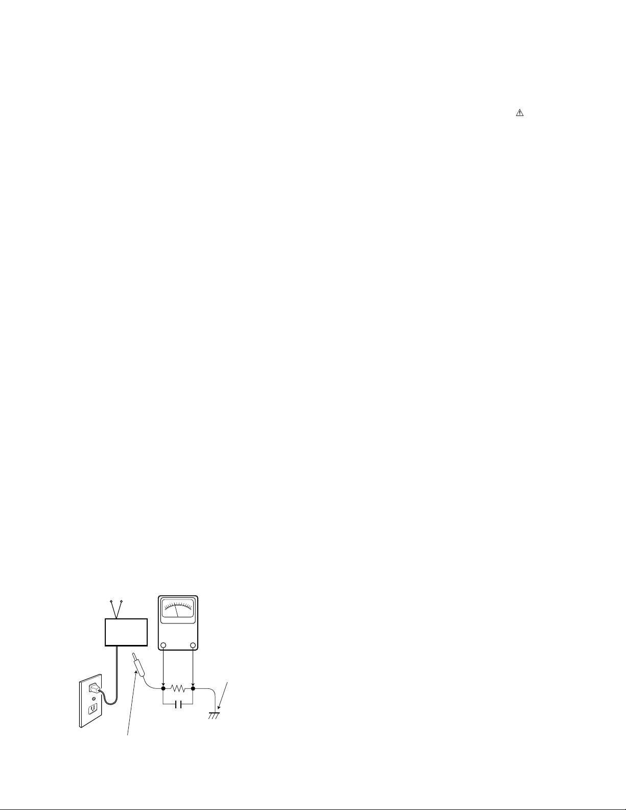
LEAKAGE CURRENT CHECK
Plug the AC line cord directly into a 120 VAC outlet. (Do not use an
isolation transformer for this check.) Use an AC voltmeter, that has
5000 ohms per volt or more sensitivity. Connect a 1500 ohm 10 watt
resistor, paralleled by a 0.15 µF 150 VAC capacitor, between a
known good earth ground (water pipe, conduit, etc.) and all
exposed metal parts of the cabinet (antennas, handle bracket, metal
cabinet, screw heads, metal overlays, control shafts, etc.). Measure
the AC voltage across the 1500 ohm resistor. The AC voltage should
not exceed 750 mV. A reading exceeding 750 mV indicates that a
dangerous potential exists. The fault must be located and corrected. Repeat the above test with the receiver power plug reversed.
NEVER RETURN A RECEIVER TO THE CUSTOMER WITHOUT
TAKING THE NECESSARY CORRECTIVE ACTION.
PRODUCT SAFETY NOTICE
When replacing components in a receiver, always keep in mind
the necessary product safety precautions. Pay special attention
to the replacement of components marked with a in the parts
list and in the schematic diagrams. To ensure safe product operation, it is necessary to replace those components with the exact
same PARTS.
SERVICING ELECTROSTATICALLY SENSATIVE DEVICES
Semiconductors (solid-state devices) that can be damaged by static
electricity are referred to as Electrostatically Sensitive (ES) devices.
Examples of typical ES devices are: Integrated Circuits (IC), FieldEffect Transistors (FET), and “chip” components. The following
techniques should be observed strictly, to reduce the occurrence of
semiconductor damage due to electrostatic discharge.
1. Immediately prior to handling any semiconductor component or
an assembly containing a semiconductor device or devices, discharge the electrostatic buildup on your body by touching a
known earth ground. You may also obtain and wear a commercially available discharging wrist strap device.
CAUTION: Be sure to remove the wrist strap before applying
power to any unit being serviced.
2. After removing an ES equipped assembly, place it on a conductive surface, such as, aluminum foil, to prevent buildup or
exposure to static electricity.
3. Use only grounded-tip soldering irons to solder or unsolder ES
devices.
4. Use only anti-static solder removal devices. Some suction-type
devices can generate static electricity adequate to damage ES
devices.
5. A replacement ES device will come packaged in protective material
(conductive foam, aluminum foil, or some comparable conductive
material). Do Not remove an ES device from its protective packaging unless you are prepared to install it immediately.
6. Precisely prior to removing an ES device from its protective packaging, touch the protective packaging to the chassis or
assembly in which the device will be installed.
CAUTION: Be sure that no power is applied to the chassis or circuit
assembly.
7. Incidental body movements, such as, lifting a foot from a carpeted
floor or the rubbing of fabric together can generate static electricity
sufficient to damage ES devices. Therefore, minimize all body
movements while handling exposed (unpackaged) ES devices.
SAFETY INSTRUCTIONS
AC OUTLET
READING SHOULD NOT EXCEED 750 mV.
TELEVISION
RECEIVER
To be touched to all of exposed metal parts.
Voltmeter Hook-up for Leakage Current Check.
AC VOLTMETER
(5000 ohms per volt or more sensitivity)
1500 ohm
10 watt
0.15 μF 150V AC
Good earth ground
such as a water pipe,
conduit, etc.
Page 3
GENERAL
This set has an On-screen Service Menu system included in
the CPU that allows remote operation for most of the service adjustments.
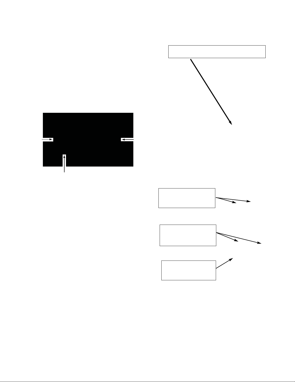
ON-SCREEN SERVICE MENU SYSTEM
1. Enter the Service Menu:
• Turn off the receiver and disconnect the AC power
supply.
• While pressing the Volume (–) button on the televi-
sion, reconnect the AC power supply. The Service
Menu will now appear. The remote can now be used
to make adjustments. See Figure 1 below.
2. Service Adjustments:
• Press the Channel or key to select the desired
service menu item you want to adjust. See page 4
for the On-screen Service Menu.
• Use the Volume + or – key to adjust the data.
The + or – keys will increase or decrease the data
sequentially.
3. Exit from the Service Menu:
• Press the MENU key to turn off the Service Menu
display.
— 3 —
SERVICE ADJUSTMENTS
Menu:
Exit Service Menu
Volume – : Enter Service Menu
Figure 1. Service Menu Display
HEX DATA
Volume + / –:
Adjust Service Menu
Channel :
Select Item
ITEM NO.
TITLE
V e r 0 5 1
0 8 6 V O L
3 0
Page 4

— 4 —
ON-SCREEN SERVICE MENU
Table 1. ON-SCREEN SERVICE MENU
When IC802 (EEPROM) is replaced, check the bus data to confirm they are the same as below. See page 3 for
On-Screen Service Menu access and adjustments.
PROGRAM CODES
The microprossesor used in this model is a multi-purpose type and is used in several different models. To ensure
proper operation and the correct features for your particular model, the program codes must be correct.
Note 1. Option Data 1 (NO. 087 OPT) should be hexadecimal 00. See 087 above. If this program code is wrong the
TV will not operate properly.
Note 2. Option Data 2 (NO. 088 OP2) should be hexadecimal 02. See 088 above. If this program code is wrong the
TV will not operate properly.
086 VOL 30h Volume setup inspection
087 OP1 00h Option 1 Data
088 OP2 02h Option 2 Data
101 1R00 00h ROM Correction Data
102 1R02 00h ROM Correction Data
↓↓ ↓ ↓
197 2R47 00h ROM Correction Data
198 2R48 00h ROM Correction Data
No. Title Initial Data Note
Page 5

— 5 —
POWER FAILURE CIRCUIT
Check the following if the unit is turned off by the power
failure detector.
1. Disconnect the AC power cord (120V AC line) for at least
10 seconds.
2. Connect a DC Voltmeter to the circuits shown below.
3. Press the Power key and check for the proper voltage
supplies.
4. If any of these voltages is low, the power failure detector should turn the unit off within three seconds.
5. Check all circuits shown below.
Note: This unit is equipped with a Power Surge Protection
feature included in the CPU. If power failure occurs
three times within 15 minutes, the CPU will stop functioning automatically to help prevent secondary
damage. (TV will not turn on by pressing the power
key.) To reset the operating programs within the CPU,
disconnect the AC power cord for at least 10 seconds.
This unit is equipped with a Power Failure Detector function
included in the CPU which checks for an abnormal condition in the chassis power supplies, including the power
supply for the LVDS (LCD Panel).
If, while the power is on, a failure is caused by any of the
following that results in a low voltage supply, the CPU will
turn the unit off in 1.5 seconds to prevent further damage:
•
Failure within the power supply circuits.
•
A short circuit in the load side from the supply.
1. Power Failure 1: Detected voltage failure for digital
circuits. (Connected to IC801 pin 36.)
2. Power Failure 2: Detected voltage failure for analog
circuits. (Connected to IC801 pin 32.)
(Normal: High; Failure: Low)
If, while the power is off, the power is switched on and any
of these failures remains uncorrected, the CPU will shut off
the power within three seconds.
Page 6

— 6 —
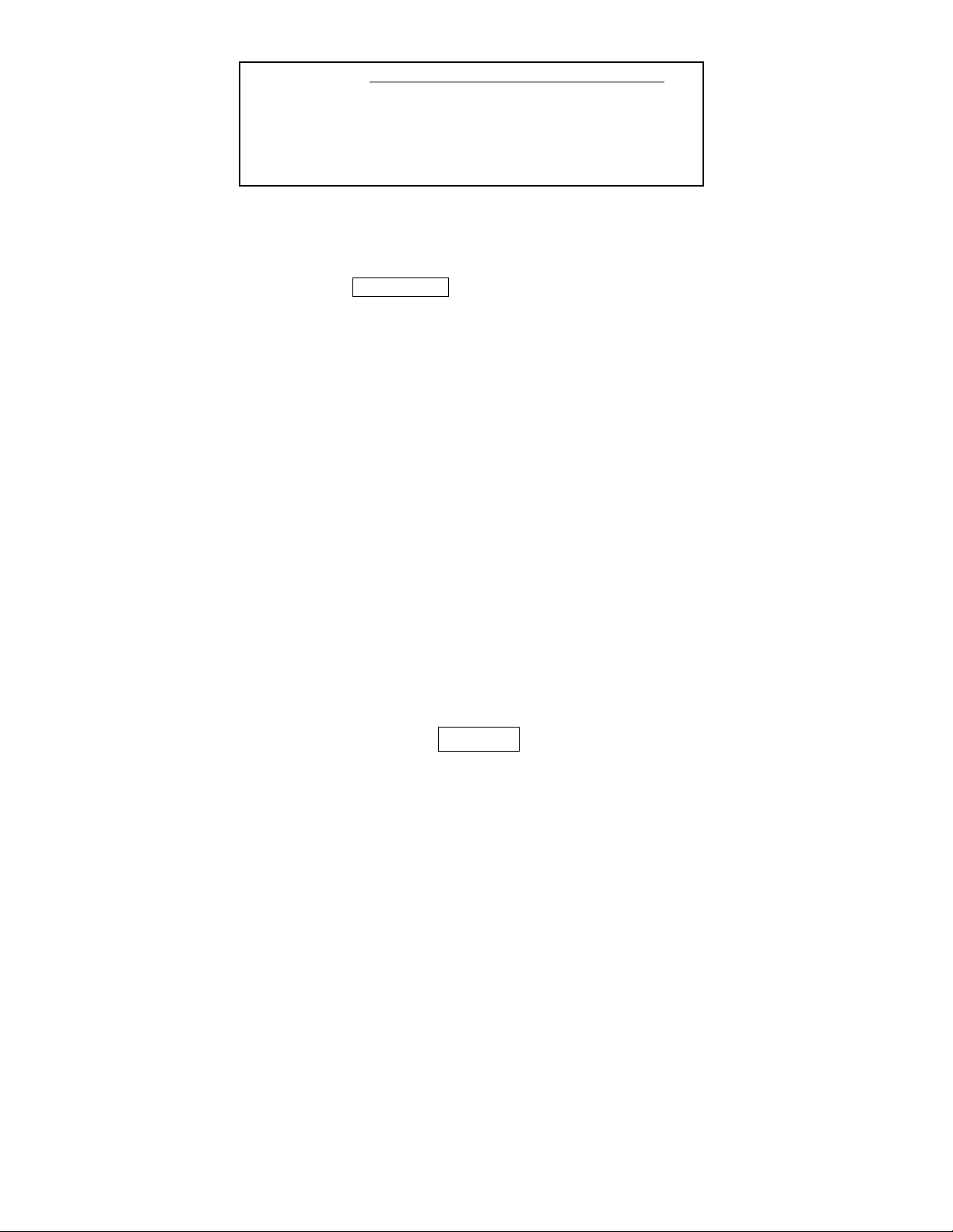
STAND REMOVAL
Note: Position TV face down on a padded or cush-
ioned surface to protect the screen and finish.
Remove 2 screws to take the stand off.
MECHANICAL DISASSEMBLY
CAUTION: This LCD TV uses several different kinds of
screws. Using the correct screw is necessary to prevent damage. Lead wires must
be redressed to their previous locations
after servicing.
CABINET BACK REMOVAL
Remove 6 screws (A 3X10) and 1 screw (B 3X6).
Release the hooks in 2 places at the top by grasping the bottom of the back and lifting. Take the cabinet back off.
Note: The cabinet back can be removed without removing the stand.
Hook
B
A
Page 7
— 7 —
POWER BOARD REMOVAL
Remove 2 screws to take off the power unit.
MAIN BOARD REMOVAL
Remove 4 screws to take off the main board.
Power Unit
Main Board
ELECTROSTATICALLY SENSATIVE DEVICES
Many solid-state devices (especially Integrated
Circuits) are Electrostatically Sensitive, and, therefore,
require special handling techniques as described
under “Servicing Electrostatically Sensitive Devices,”
on page two in this service literature.
Page 8

— 8 —
MECHANICAL DISASSEMBLY (CONT.)
SPEAKER REMOVAL
Lift both speakers from cabinet.
MOUNTING BRACKET AND SPEAKER REMOVAL
Remove 11 screws to take off the mouniting bracket and the left and
right speakers.
Mounting
Bracket
Page 9

— 9 —
CONTROL BOARD REMOVAL
Remove 2 screws to take off the control board with the button
assembly parts.
LCD PANEL REMOVAL
Lift panel from cabinet.
LCD Panel
Control Board
Page 10
— 10 —
CHASSIS ELECTRICAL PARTS LIST
CAUTION: To Protect against electrical shock and for continued product safety, refer to SAFETY PRECAUTIONS
and PRODUCT SAFETY NOTICE on Page 2.
PRODUCT SAFETY NOTICE
PRODUCT SAFETY SHOULD BE CONSIDERED WHEN A REPLACEMENT IS MADE IN ANY AREA OF A RECEIVER.
COMPONENTS INDICATED BY A IN THIS PARTS LIST AND THE SCHEMATIC DIAGRAM DESIGNATE
COMPONENTS IN WHICH SAFETY CAN BE OF SPECIAL SIGNIFICANCE. IT IS PARTICULARLY RECOMMENDED
THAT ONLY PARTS DESIGNATED ON THE FOLLOWING PARTS LIST BE USED FOR COMPONENT REPLACEMENT
DESIGNATED BY A . NO DEVIATIONS FROM RESISTANCE,WATTAGE, AND VOLTAGE RATINGS MAY BE MADE
FOR REPLACEMENT ITEMS DESIGNATED BY A .
Schematic
Location
Part No.
Description
Schematic
Location
Part No.
Description
Note: Schematic part location numbers may not always match with the part descriptions.
The part descriptions are correct and should be used.
CAPACITORS
RESISTORS
NOTES:
Read description of the Capacitor as follows:
(Example)
CERAMIC 100P K 50V
Rated Voltage
Tolerance Symbols:
Less than 10pF
A : Not specified B : ±0.1pF C : ±0.25pF
D : ±0.5pF E : +0 -1pF F : ±1PF
G : ±2pF H : +0.1 -0pF L : +0 -0.1pF
R : ±0.25 -0pF S : +0-0.25pF
More than 10pF
A :Not specified B : ±0.1% C : ±0.25%
D : ±0.5% F : ±1% G : ±2%
H :±3% J :±5% K :±10%
L :±15% M :±20% N :±30%
P :+100-0% Q :+30-10% T :+50-10%
U :+75-10% V :+20-10% W :+100-10%
X :+40-20% Y :+150-10% Z : +80-20%
Rated value: P=pico farad, U=micro farad
Material:
CERAMIC........... Ceramic
MT-PAPER......... Metallized Paper
POLYESTER...... Polyester
MT-POLYEST.....Metallized Polyester
POLYPRO.......... Polypropylene
MT-POLYPRO.... Metallized Polypropylene
COMPO FILM..... Composite Film
MT-COMPO........ Metallized Composite
STYRENE........... Styrene
TA-SOLID........... Tantalum Solid
AL-SOLID........... Aluminium Solid
ELECT................ Electrolytic
NP-ELECT.......... Non-polarised Electrolytic
OS-SOLID.......... Aluminium Solid with Organic
Semiconductive Electrolytic
NOTES:
Read description of the Resistor as follows:
(Example)
CARBON 4.7K J A 1/4W
Rated Wattage
Performance Symbols:
A...General B...Non-flammable
Z...Low noise
Other... Temperature coefficient
Tolerance Symbols:
A...0.05% B...0.1% C...25%
D...0.5% F...1% G...2%
J...5% K...10% M...20%
P...+5 -15%
Rated Value, ohms:
K...1,000 M...1,000,000
Material:
CARBON .............
MT-FILM ..............
OXIDE-MT ...........
SOLID ..................
MT-GLAZE ...........
WIRE WOUND .....
CERAMIC RES ....
FUSIBLE RES .....
Carbon
Metal Film
Oxide Metal Film
Composition
Metal Glaze
Wire Wound
Ceramic
Fusible
Page 11

— 11 —
Schematic
Location
Part No.
Description
CAPACITORS
C001 CPXLB1C100YAN NP-ELECT 10U M 16V
C001 CPXLB1C100ZAN NP-ELECT 10U M 16V
C002 CK1H104ZLZFNG CERAMIC 0.1U Z 50V
C006 CEXLB1H4R7VDN ELECT 4.7U M 50V
C006 CEXLB1H4R7WAN ELECT 4.7U M 50V
C007 CEXLB1V470VDN ELECT 47U M 35V
C007 CEXLB1V470WAN ELECT 47U M 35V
C008 CK1H102KLZBNG CERAMIC 1000P K 50V
C009 CK1H102KLZBNG CERAMIC 1000P K 50V
C010 CK1H104ZLZFNG CERAMIC 0.1U Z 50V
C011 CK1H104ZLZFNG CERAMIC 0.1U Z 50V
C013 CPXLB1C100YAN NP-ELECT 10U M 16V
C013 CPXLB1C100ZAN NP-ELECT 10U M 16V
C015 CEXLB1C222VDN ELECT 2200U M 16V
C016 CEXLB1H100VDN ELECT 10U M 50V
C016 CEXLB1H100WAN ELECT 10U M 50V
C017 CEXLB1H100VDN ELECT 10U M 50V
C017 CEXLB1H100WAN ELECT 10U M 50V
C018 CK1H104ZLZFNG CERAMIC 0.1U Z 50V
C019 CK1H104ZLZFNG CERAMIC 0.1U Z 50V
C681 CK1H104ZLZFNG CERAMIC 0.1U Z 50V
C684 CK1H104ZLZFNG CERAMIC 0.1U Z 50V
C687 CK1H104ZLZFNG CERAMIC 0.1U Z 50V
C697 CK1H104ZLZFNG CERAMIC 0.1U Z 50V
C703 CK1H104ZLZFNG CERAMIC 0.1U Z 50V
C704 CK1H104ZLZFNG CERAMIC 0.1U Z 50V
C705 CK1H104ZLZFNG CERAMIC 0.1U Z 50V
C706 CK1H104ZLZFNG CERAMIC 0.1U Z 50V
C708 CK1H104ZLZFNG CERAMIC 0.1U Z 50V
C710 CK1H104ZLZFNG CERAMIC 0.1U Z 50V
C721 CK1H104ZLZFNG CERAMIC 0.1U Z 50V
C723 CK1H104ZLZFNG CERAMIC 0.1U Z 50V
C800 RGFR000ZTCANL MT-GLAZE 0.000 ZA 1/10W
C804 RGF1003JTCANL MT-GLAZE 100K JA 1/10W
C805 CC1H220JLZCNG CERAMIC 22P J 50V
C806 CC1H220JLZCNG CERAMIC 22P J 50V
C807 CK1H103ZLZFNG CERAMIC 0.01U Z 50V
C811 CK1H104ZLZFNG CERAMIC 0.1U Z 50V
C813 CEXLB1V470VDN ELECT 47U M 35V
C813 CEXLB1V470WAN ELECT 47U M 35V
C814 CK1H222KLZBNG CERAMIC 2200P K 50V
C815 CC1H220JLZCNG CERAMIC 22P J 50V
C816 CC1H220JLZCNG CERAMIC 22P J 50V
C820 CK1H103ZLZFNG CERAMIC 0.01U Z 50V
C825 CC1H470JLZCNG CERAMIC 47P J 50V
C826 CK1H104ZLZFNG CERAMIC 0.1U Z 50V
C827 CK1H104ZLZFNG CERAMIC 0.1U Z 50V
C829 CK1H104ZLZFNG CERAMIC 0.1U Z 50V
C834 CEXLB0J221VDN ELECT 220U M 6.3V
C834 CEXLB0J221WAN ELECT 220U M 6.3V
C835 CK1H104ZLZFNG CERAMIC 0.1U Z 50V
C836 CC1H120JLZCNG CERAMIC 12P J 50V
C837 CC1H120JLZCNG CERAMIC 12P J 50V
C839 CK1H103ZLZFNG CERAMIC 0.01U Z 50V
C840 CK1H333KLZBNG CERAMIC 0.033U K 50V
C841 CEXLB1H2R2VDN ELECT 2.2 U M 50V
C841 CEXLB1H2R2WAN ELECT 2.2U M 50V
C842 CK1H104ZLZFNG CERAMIC 0.1U Z 50V
C1000 CK1H104ZLZFNG CERAMIC 0.1U Z 50V
C1001 CEXLB1H100VDN ELECT 10U M 50V
C1001 CEXLB1H100WAN ELECT 10U M 50V
C1002 CEXLB1H100VDN ELECT 10U M 50V
C1002 CEXLB1H100WAN ELECT 10U M 50V
C1003 CEXLB1H4R7VDN ELECT 4.7U M 50V
C1003 CEXLB1H4R7WAN ELECT 4.7U M 50V
C1004 CEXLB1H4R7VDN ELECT 4.7U M 50V
C1004 CEXLB1H4R7WAN ELECT 4.7U M 50V
C1011 CEXLB1H4R7VDN ELECT 4.7U M 50V
C1011 CEXLB1H4R7WAN ELECT 4.7U M 50V
C1012 CEXLB1H4R7VDN ELECT 4.7U M 50V
C1012 CEXLB1H4R7WAN ELECT 4.7U M 50V
C1013 CEXLB1H4R7VDN ELECT 4.7U M 50V
C1013 CEXLB1H4R7WAN ELECT 4.7U M 50V
C1014 CEXLB1H4R7VDN ELECT 4.7U M 50V
C1014 CEXLB1H4R7WAN ELECT 4.7U M 50V
C1015 CEXLB1H4R7VDN ELECT 4.7U M 50V
C1015 CEXLB1H4R7WAN ELECT 4.7U M 50V
C1016 CEXLB1H4R7VDN ELECT 4.7U M 50V
C1016 CEXLB1H4R7WAN ELECT 4.7U M 50V
C1017 CEXLB1H4R7VDN ELECT 4.7U M 50V
C1017 CEXLB1H4R7WAN ELECT 4.7U M 50V
C1201 CEXLB1V470VDN ELECT 47U M 35V
C1201 CEXLB1V470WAN ELECT 47U M 35V
C1202 CK1H104ZLZFNG CERAMIC 0.1U Z 50V
C1205 CEXLB1V470VDN ELECT 47U M 35V
C1205 CEXLB1V470WAN ELECT 47U M 35V
C1251 CK1H104ZLZFNG CERAMIC 0.1U Z 50V
C1600 CEXLB1E102VDN ELECT 1K U M 25V
C1601 CK1H104ZLZFNG CERAMIC 0.1U Z 50V
C1602 CE0J102MZVANN ELECT 1000U M 6.3V
C1603 CK1A105ZLZFNG CERAMIC 1U Z 10V
C1604 CK1H104ZLZFNG CERAMIC 0.1U Z 50V
C1610 CK1H104ZLZFNG CERAMIC 0.1U Z 50V
C1611 CK1A105ZLZFNG CERAMIC 1U Z 10V
C1613 CK1H104ZLZFNG CERAMIC 0.1U Z 50V
C1614 CEXLB0J221VDN ELECT 220U M 6.3V
C1614 CEXLB0J221WAN ELECT 220U M 6.3V
C1615 CEXLB0J221VDN ELECT 220U M 6.3V
C1615 CEXLB0J221WAN ELECT 220U M 6.3V
C1618 CK1A105ZLZFNG CERAMIC 1U Z 10V
C1619 CK1H104ZLZFNG CERAMIC 0.1U Z 50V
C1620 CK1H104ZLZFNG CERAMIC 0.1U Z 50V
C1621 CK1A105ZLZFNG CERAMIC 1U Z 10V
C1622 CK1A105ZLZFNG CERAMIC 1U Z 10V
C1623 CEXLB1H100VDN ELECT 10U M 50V
C1623 CEXLB1H100WAN ELECT 10U M 50V
C1630 CEXLB1C101VDN ELECT 100U M 16V
Schematic
Location
Part No.
Description
Page 12

— 12 —
Schematic
Location
Part No.
Description
Schematic
Location
Part No.
Description
C1630 CEXLB1C101WAN ELECT 100U M 16V
C1631 CK1H104ZLZFNG CERAMIC 0.1U Z 50V
C1632 CK1H104ZLZFNG CERAMIC 0.1U Z 50V
C1633 CEXLB0J102VDN ELECT 1000U M 6.3V
C1633 CEXLB0J102WAN ELECT 1000U M 6.3V
C1634 CK1A105ZLZFNG CERAMIC 1U Z 10V
C1640 CEXLB1C101VDN ELECT 100U M 16V
C1640 CEXLB1C101WAN ELECT 100U M 16V
C1641 CK1H104ZLZFNG CERAMIC 0.1U Z 50V
C1642 CK1H104ZLZFNG CERAMIC 0.1U Z 50V
C1643 CEXLB1C101VDN ELECT 100U M 16V
C1643 CEXLB1C101WAN ELECT 100U M 16V
C1660 CEXLB1V471WAN ELECT 470U M 35V
C1661 CK1H104ZLZFNG CERAMIC 0.1U Z 50V
C1662 CK1H103ZLZFNG CERAMIC 0.01U Z 50V
C1663 CC1H470JLZCNG CERAMIC 47P J 50V
C1664 CK1H103ZLZFNG CERAMIC 0.01U Z 50V
C1665 CK1H104ZLZFNG CERAMIC 0.1U Z 50V
C1666 CEXLB1E102VDN ELECT 1K U M 25V
C1667 CK1H104ZLZFNG CERAMIC 0.1U Z 50V
C1800 CK1H104ZLZFNG CERAMIC 0.1U Z 50V
C1902 CEXLB1H100VDN ELECT 10U M 50V
C1902 CEXLB1H100WAN ELECT 10U M 50V
C1904 CK1H104ZLZFNG CERAMIC 0.1U Z 50V
C1905 CC1H470JLZCNG CERAMIC 47P J 50V
C3200 CK1H104ZLZFNG CERAMIC 0.1U Z 50V
C3201 CK1A105ZLZFNG CERAMIC 1U Z 10V
C3202 CK1A105ZLZFNG CERAMIC 1U Z 10V
C3203 CK1H104ZLZFNG CERAMIC 0.1U Z 50V
C3204 CK1H223KLZBNG CERAMIC 0.022U K 50V
C3205 CK1H222KLZBNG CERAMIC 2200P K 50V
C3206 CK1H104ZLZFNG CERAMIC 0.1U Z 50V
C3208 CK1A105ZLZFNG CERAMIC 1U Z 10V
C3209 CK1A105ZLZFNG CERAMIC 1U Z 10V
C3210 CK1H104ZLZFNG CERAMIC 0.1U Z 50V
C3211 CK1A105ZLZFNG CERAMIC 1U Z 10V
C3212 CK1A105ZLZFNG CERAMIC 1U Z 10V
C3213 CK1H104ZLZFNG CERAMIC 0.1U Z 50V
C3214 CK1A105ZLZFNG CERAMIC 1U Z 10V
C3215 CK1H222KLZBNG CERAMIC 2200P K 50V
C3216 CK1H104ZLZFNG CERAMIC 0.1U Z 50V
C3218 CK1C224KLZBNG CERAMIC 0.22U K 16V
C3219 CK1A105ZLZFNG CERAMIC 1U Z 10V
C3220 CK1A105ZLZFNG CERAMIC 1U Z 10V
C3221 CK1A105ZLZFNG CERAMIC 1U Z 10V
C3222 CK1H104ZLZFNG CERAMIC 0.1U Z 50V
C3223 CEXLB1C222VDN ELECT 2200U M 16V
C5503 CK1H104ZLZFNG CERAMIC 0.1U Z 50V
C5504 CK1A105ZLZFNG CERAMIC 1U Z 10V
C5505 CK1H102KLZBNG CERAMIC 1000P K 50V
C5506 CK1H104ZLZFNG CERAMIC 0.1U Z 50V
C5507 CK1H104ZLZFNG CERAMIC 0.1U Z 50V
C5508 CK1H104ZLZFNG CERAMIC 0.1U Z 50V
C5509 CK1H104ZLZFNG CERAMIC 0.1U Z 50V
C5510 CK1A105ZLZFNG CERAMIC 1U Z 10V
C5511 CEXLB1H100VDN ELECT 10U M 50V
C5511 CEXLB1H100WAN ELECT 10U M 50V
C5512 CEXLB1H100VDN ELECT 10U M 50V
C5512 CEXLB1H100WAN ELECT 10U M 50V
C5513 CK1H104ZLZFNG CERAMIC 0.1U Z 50V
C5515 CC1H470JLZCNG CERAMIC 47P J 50V
C5516 CC1H470JLZCNG CERAMIC 47P J 50V
C5517 CK1H104ZLZFNG CERAMIC 0.1U Z 50V
C5518 CEXLB1H100VDN ELECT 10U M 50V
C5518 CEXLB1H100WAN ELECT 10U M 50V
C5519 CK1H104ZLZFNG CERAMIC 0.1U Z 50V
C5521 CEXLB1H100VDN ELECT 10U M 50V
C5521 CEXLB1H100WAN ELECT 10U M 50V
C5523 CK1A105ZLZFNG CERAMIC 1U Z 10V
C5529 CK1H104ZLZFNG CERAMIC 0.1U Z 50V
C5532 CK1A105ZLZFNG CERAMIC 1U Z 10V
C5533 CEXLB0J221VDN ELECT 220U M 6.3V
C5533 CEXLB0J221WAN ELECT 220U M 6.3V
C5534 CK1H104ZLZFNG CERAMIC 0.1U Z 50V
C5536 CEXLB0J221VDN ELECT 220U M 6.3V
C5536 CEXLB0J221WAN ELECT 220U M 6.3V
C5537 CK1A105ZLZFNG CERAMIC 1U Z 10V
C5538 CK1H103ZLZFNG CERAMIC 0.01U Z 50V
C5539 CK1H104ZLZFNG CERAMIC 0.1U Z 50V
C5542 CK1H104ZLZFNG CERAMIC 0.1U Z 50V
C5543 CK1H104ZLZFNG CERAMIC 0.1U Z 50V
C5544 CK1H104ZLZFNG CERAMIC 0.1U Z 50V
C5545 CK1H104ZLZFNG CERAMIC 0.1U Z 50V
C5547 CK1H104ZLZFNG CERAMIC 0.1U Z 50V
C5548 CK1H104ZLZFNG CERAMIC 0.1U Z 50V
C5549 CK1H104ZLZFNG CERAMIC 0.1U Z 50V
C5551 CK1H104ZLZFNG CERAMIC 0.1U Z 50V
C5552 CK1H104ZLZFNG CERAMIC 0.1U Z 50V
C5553 CEXLB1V470VDN ELECT 47U M 35V
C5553 CEXLB1V470WAN ELECT 47U M 35V
C5554 CK1H104ZLZFNG CERAMIC 0.1U Z 50V
C5555 CK1H104ZLZFNG CERAMIC 0.1U Z 50V
C5557 CK1H104ZLZFNG CERAMIC 0.1U Z 50V
C5558 CK1H102KLZBNG CERAMIC 1000P K 50V
C5560 CK1H104ZLZFNG CERAMIC 0.1U Z 50V
C5564 CK1H104ZLZFNG CERAMIC 0.1U Z 50V
C5565 CK1H104ZLZFNG CERAMIC 0.1U Z 50V
C5566 CK1H104ZLZFNG CERAMIC 0.1U Z 50V
C5567 CK1H104ZLZFNG CERAMIC 0.1U Z 50V
C5568 CK1H104ZLZFNG CERAMIC 0.1U Z 50V
C5570 CK1H104ZLZFNG CERAMIC 0.1U Z 50V
C5572 CK1H104ZLZFNG CERAMIC 0.1U Z 50V
C5573 CK1H104ZLZFNG CERAMIC 0.1U Z 50V
C5574 CK1H104ZLZFNG CERAMIC 0.1U Z 50V
C5575 CK1A105ZLZFNG CERAMIC 1U Z 10V
C5576 CK1H104ZLZFNG CERAMIC 0.1U Z 50V
C5577 CK1H104ZLZFNG CERAMIC 0.1U Z 50V
Page 13

— 13 —
Schematic
Location
Part No.
Description
Schematic
Location
Part No.
Description
C5578 CEXLB0J221VDN ELECT 220U M 6.3V
C5578 CEXLB0J221WAN ELECT 220U M 6.3V
C5580 CK1H104ZLZFNG CERAMIC 0.1U Z 50V
C5581 CK1H104ZLZFNG CERAMIC 0.1U Z 50V
C5582 CK0J106KGMBNG CERAMIC 10U K 6.3V
C5583 CK0J106KGMBNG CERAMIC 10U K 6.3V
C5701 CEXLB1V470VDN ELECT 47U M 35V
C5701 CEXLB1V470WAN ELECT 47U M 35V
C5702 CK1H104ZLZFNG CERAMIC 0.1U Z 50V
C5704 CK1H104ZLZFNG CERAMIC 0.1U Z 50V
C5705 CK1H104ZLZFNG CERAMIC 0.1U Z 50V
C5706 CK1H104ZLZFNG CERAMIC 0.1U Z 50V
C5707 CK1H104ZLZFNG CERAMIC 0.1U Z 50V
C5708 CK1H104ZLZFNG CERAMIC 0.1U Z 50V
C5709 CK1H104ZLZFNG CERAMIC 0.1U Z 50V
C5710 CK1H103ZLZFNG CERAMIC 0.01U Z 50V
C5711 CK1H103ZLZFNG CERAMIC 0.01U Z 50V
C5712 CK1H103ZLZFNG CERAMIC 0.01U Z 50V
C5713 CK1H103ZLZFNG CERAMIC 0.01U Z 50V
C5714 CK1H103ZLZFNG CERAMIC 0.01U Z 50V
C5715 CK1H104ZLZFNG CERAMIC 0.1U Z 50V
C5721 CK0J475KLZBNG CERAMIC 4.7U K 6.3V
C5801 CK1H104ZLZFNG CERAMIC 0.1U Z 50V
C5803 CC1H120JLZCNG CERAMIC 12P J 50V
C5804 CC1H150JLZCNG CERAMIC 15P J 50V
C5805 CC1H270JLZCNG CERAMIC 27P J 50V
C5806 CC1H680JLZCNG CERAMIC 68P J 50V
C5807 CK1C224KLZBNG CERAMIC 0.22U K 16V
C5808 CK1C224KLZBNG CERAMIC 0.22U K 16V
C5809 CK1H104ZLZFNG CERAMIC 0.1U Z 50V
C5812 CC1H120JLZCNG CERAMIC 12P J 50V
C5813 CC1H150JLZCNG CERAMIC 15P J 50V
C5814 CC1H270JLZCNG CERAMIC 27P J 50V
C5815 CC1H680JLZCNG CERAMIC 68P J 50V
C5816 CK1C224KLZBNG CERAMIC 0.22U K 16V
C5901 CK1A474KLZBNG CERAMIC 0.47U K 10V
C5904 CK1H104ZLZFNG CERAMIC 0.1U Z 50V
C5905 CEXLB1H100VDN ELECT 10U M 50V
C5905 CEXLB1H100WAN ELECT 10U M 50V
C5959 CC1H120JLZCNG CERAMIC 12P J 50V
C6051 CK1A105ZLZFNG CERAMIC 1U Z 10V
C6052 CK1A105ZLZFNG CERAMIC 1U Z 10V
C6053 CEXLB0J221VDN ELECT 220U M 6.3V
C6053 CEXLB0J221WAN ELECT 220U M 6.3V
C6054 CK1H104ZLZFNG CERAMIC 0.1U Z 50V
C6086 CK1H104ZLZFNG CERAMIC 0.1U Z 50V
C6087 CEXLB1V470VDN ELECT 47U M 35V
C6087 CEXLB1V470WAN ELECT 47U M 35V
C6090 CEXLB0J221VDN ELECT 220U M 6.3V
C6090 CEXLB0J221WAN ELECT 220U M 6.3V
C6091 CK1A105ZLZFNG CERAMIC 1U Z 10V
C6094 CK1A105ZLZFNG CERAMIC 1U Z 10V
C6099 CK1H104ZLZFNG CERAMIC 0.1U Z 50V
C6103 CK1H104ZLZFNG CERAMIC 0.1U Z 50V
C6105 CC1H3R0CLZCNG CERAMIC 3P C 50V
C6106 CC1H390JLZCNG CERAMIC 39P J 50V
C6107 CK1A105ZLZFNG CERAMIC 1U Z 10V
C6109 CK1H103ZLZFNG CERAMIC 0.01U Z 50V
C6127 CEXLB0J102VDN ELECT 1000U M 6.3V
C6127 CEXLB0J102WAN ELECT 1000U M 6.3V
C6144 CK1H104ZLZFNG CERAMIC 0.1U Z 50V
C6145 CK1H104ZLZFNG CERAMIC 0.1U Z 50V
C6151 CC1H220JLZCNG CERAMIC 22P J 50V
C6153 CC1H220JLZCNG CERAMIC 22P J 50V
C6155 CK1H104ZLZFNG CERAMIC 0.1U Z 50V
C6170 CK1H104ZLZFNG CERAMIC 0.1U Z 50V
C6171 CEXLB1V471WAN ELECT 470U M 35V
C6172 CK1H104ZLZFNG CERAMIC 0.1U Z 50V
C6173 CC1H180JLZCNG CERAMIC 18P J 50V
C6174 CK1H104ZLZFNG CERAMIC 0.1U Z 50V
C6175 CC1H180JLZCNG CERAMIC 18P J 50V
C6176 CEXLB0J102VDN ELECT 1000U M 6.3V
C6176 CEXLB0J102WAN ELECT 1000U M 6.3V
C6177 CEXLB1V471WAN ELECT 470U M 35V
C6178 CK1H104ZLZFNG CERAMIC 0.1U Z 50V
C6180 CK1H102KLZBNG CERAMIC 1000P K 50V
C6181 CK1H104ZLZFNG CERAMIC 0.1U Z 50V
C6201 CK1H104ZLZFNG CERAMIC 0.1U Z 50V
C6202 CK1H104ZLZFNG CERAMIC 0.1U Z 50V
C6203 CK1H473KLZBNG CERAMIC 0.047U K 50V
C6204 CK1H104ZLZFNG CERAMIC 0.1U Z 50V
C6205 CK1H104ZLZFNG CERAMIC 0.1U Z 50V
C6206 CK1H473KLZBNG CERAMIC 0.047U K 50V
C6207 CK1H103ZLZFNG CERAMIC 0.01U Z 50V
C6208 CK1H104ZLZFNG CERAMIC 0.1U Z 50V
C6209 CK1H104ZLZFNG CERAMIC 0.1U Z 50V
C6211 CK1H473KLZBNG CERAMIC 0.047U K 50V
C6212 CK1H104ZLZFNG CERAMIC 0.1U Z 50V
C6213 CK1H473KLZBNG CERAMIC 0.047U K 50V
C6214 CK1H473KLZBNG CERAMIC 0.047U K 50V
C6215 CK1H103ZLZFNG CERAMIC 0.01U Z 50V
C6216 CK1H473KLZBNG CERAMIC 0.047U K 50V
C6217 CK1H104ZLZFNG CERAMIC 0.1U Z 50V
C6218 CK1H104ZLZFNG CERAMIC 0.1U Z 50V
C6219 CK1H104ZLZFNG CERAMIC 0.1U Z 50V
C6221 CK1H104ZLZFNG CERAMIC 0.1U Z 50V
C6230 CEXLB0J221VDN ELECT 220U M 6.3V
C6230 CEXLB0J221WAN ELECT 220U M 6.3V
C6231 CC1H150JLZCNG CERAMIC 15P J 50V
C6232 CC1H150JLZCNG CERAMIC 15P J 50V
C6233 CK1H104ZLZFNG CERAMIC 0.1U Z 50V
C6234 CK1H104ZLZFNG CERAMIC 0.1U Z 50V
C6235 CK1H104ZLZFNG CERAMIC 0.1U Z 50V
C6236 CK1H104ZLZFNG CERAMIC 0.1U Z 50V
C6237 CK1H104ZLZFNG CERAMIC 0.1U Z 50V
C6238 CK1H104ZLZFNG CERAMIC 0.1U Z 50V
C6239 CK1H104ZLZFNG CERAMIC 0.1U Z 50V
C6241 CK1H104ZLZFNG CERAMIC 0.1U Z 50V
Page 14

— 14 —
Schematic
Location
Part No.
Description
Schematic
Location
Part No.
Description
C6242 CK1H104ZLZFNG CERAMIC 0.1U Z 50V
C6243 CK1H104ZLZFNG CERAMIC 0.1U Z 50V
C6244 CK1H104ZLZFNG CERAMIC 0.1U Z 50V
C6245 CK1H104ZLZFNG CERAMIC 0.1U Z 50V
C6246 CK1H104ZLZFNG CERAMIC 0.1U Z 50V
C6250 CEXLB1H4R7VDN ELECT 4.7U M 50V
C6250 CEXLB1H4R7WAN ELECT 4.7U M 50V
C6251 CEXLB1H100VDN ELECT 10U M 50V
C6251 CEXLB1H100WAN ELECT 10U M 50V
C6252 CEXLB1C101VDN ELECT 100U M 16V
C6252 CEXLB1C101WAN ELECT 100U M 16V
C6253 CEXLB1H4R7VDN ELECT 4.7U M 50V
C6253 CEXLB1H4R7WAN ELECT 4.7U M 50V
C6254 CK1A474KLZBNG CERAMIC 0.47U K 10V
C6255 CK0J475KLZBNG CERAMIC 4.7U K 6.3V
C6256 CK1H123KLZBNG CERAMIC 0.012U K 50V
C6257 CK1H562KLZBNG CERAMIC 5600P K 50V
C6258 CK0J475KLZBNG CERAMIC 4.7U K 6.3V
C6259 CK0J475KLZBNG CERAMIC 4.7U K 6.3V
C6260 CK0J475KLZBNG CERAMIC 4.7U K 6.3V
C6261 CK1H272KLZBNG CERAMIC 2700P K 50V
C6262 CK1H473KLZBNG CERAMIC 0.047U K 50V
C6263 CT1A3R3KDRANG TA-SOLID 3.3U K 10V
C6264 CK1H472KLZBNG CERAMIC 4700P K 50V
C6266 CK0J475KLZBNG CERAMIC 4.7U K 6.3V
C6267 CK1A105ZLZFNG CERAMIC 1U Z 10V
C6268 CT1A100KDRANG TA-SOLID 10U K 10V
C6271 CEXLB1H100VDN ELECT 10U M 50V
C6271 CEXLB1H100WAN ELECT 10U M 50V
C6272 CK1H104ZLZFNG CERAMIC 0.1U Z 50V
C6273 CK1H104ZLZFNG CERAMIC 0.1U Z 50V
C6274 CEXLB1H100VDN ELECT 10U M 50V
C6274 CEXLB1H100WAN ELECT 10U M 50V
C6276 CK1H104ZLZFNG CERAMIC 0.1U Z 50V
C6277 CEXLB1H100VDN ELECT 10U M 50V
C6277 CEXLB1H100WAN ELECT 10U M 50V
C6278 CK1A105ZLZFNG CERAMIC 1U Z 10V
C6279 CK1H472KLZBNG CERAMIC 4700P K 50V
C6281 CK1H104ZLZFNG CERAMIC 0.1U Z 50V
C6282 CEXLB1H100VDN ELECT 10U M 50V
C6282 CEXLB1H100WAN ELECT 10U M 50V
C6283 CK1A105ZLZFNG CERAMIC 1U Z 10V
C6284 CK1H472KLZBNG CERAMIC 4700P K 50V
C6291 CEXLB1H4R7VDN ELECT 4.7U M 50V
C6291 CEXLB1H4R7WAN ELECT 4.7U M 50V
C6292 CEXLB1H4R7VDN ELECT 4.7U M 50V
C6292 CEXLB1H4R7WAN ELECT 4.7U M 50V
C6330 CEXLB1V470VDN ELECT 47U M 35V
C6330 CEXLB1V470WAN ELECT 47U M 35V
C6331 CK1H104ZLZFNG CERAMIC 0.1U Z 50V
C6332 CK1H104ZLZFNG CERAMIC 0.1U Z 50V
C6333 CK1H104ZLZFNG CERAMIC 0.1U Z 50V
C6334 RGFR000ZTCANL MT-GLAZE 0.000 ZA 1/10W
C6335 CK1H103ZLZFNG CERAMIC 0.01U Z 50V
C6336 CK1H103ZLZFNG CERAMIC 0.01U Z 50V
C6337 RGFR000ZTCANL MT-GLAZE 0.000 ZA 1/10W
C6338 CK0J475KLZBNG CERAMIC 4.7U K 6.3V
C6339 CK0J475KLZBNG CERAMIC 4.7U K 6.3V
C6340 CK1H104ZLZFNG CERAMIC 0.1U Z 50V
C6341 CEXLB0J221VDN ELECT 220U M 6.3V
C6341 CEXLB0J221WAN ELECT 220U M 6.3V
C6344 CEXLB1C101VDN ELECT 100U M 16V
C6344 CEXLB1C101WAN ELECT 100U M 16V
C6354 CK1H104ZLZFNG CERAMIC 0.1U Z 50V
C6355 CK1H104ZLZFNG CERAMIC 0.1U Z 50V
C6361 CK1A105ZLZFNG CERAMIC 1U Z 10V
C6362 CK1H104ZLZFNG CERAMIC 0.1U Z 50V
C6363 CEXLB1H4R7VDN ELECT 4.7U M 50V
C6363 CEXLB1H4R7WAN ELECT 4.7U M 50V
C6364 CEXLB1C101VDN ELECT 100U M 16V
C6364 CEXLB1C101WAN ELECT 100U M 16V
C6365 CK1H104ZLZFNG CERAMIC 0.1U Z 50V
C6367 CK1A105ZLZFNG CERAMIC 1U Z 10V
C6565 CK0J475KLZBNG CERAMIC 4.7U K 6.3V
DIODES
D801 DD1SS352----G DIODE 1SS352-(TPH3)
D801 DD1SS355----G DIODE 1SS355 TE-17
D802 DZUDZS6.2B--G ZENER DIODE UDZS6.2B TE-17
D1600 DDD1FM3-----G DIODE D1FM3
D1602 DD1SS352----G DIODE 1SS352-(TPH3)
D1602 DD1SS355----G DIODE 1SS355 TE-17
D1604 DZUDZS3.0B--G ZD UDZS3.0B-TE-17
D1610 DZUDZS3.9B--G ZD UDZS-TE-173.9B
D1620 DDD1FH3-----G DIODE D1FH3
D1621 DD1SS352----G DIODE 1SS352-(TPH3)
D1621 DD1SS355----G DIODE 1SS355 TE-17
D1630 DDD1FH3-----G DIODE D1FH3
D1631 DD1SS352----G DIODE 1SS352-(TPH3)
D1631 DD1SS355----G DIODE 1SS355 TE-17
D1640 DD1SS352----G DIODE 1SS352-(TPH3)
D1640 DD1SS355----G DIODE 1SS355 TE-17
D1660 DDD1FM3-----G DIODE D1FM3
D1661 DD1SS352----G DIODE 1SS352-(TPH3)
D1661 DD1SS355----G DIODE 1SS355 TE-17
D1683 DD1SS352----G DIODE 1SS352-(TPH3)
D1683 DD1SS355----G DIODE 1SS355 TE-17
D1902 DLSLR343MC3FN LED SLR-343MC3F
D3216 DDRB551V-30-G DIODE RB551V-30 TE-17
D6250 DD1SS355----G DIODE 1SS355 TE-17
INTEGRATED CIRCUITS
IC001 QLA42032-E--N IC LA42032-E
IC801 QXXAVC880---M IC LC874164A-58S8-E
IC802 QLE24C042M-EP IC LE24C042M-TLM-E
IC802 QXXAVC820---P IC AT24C04N-10SU-1.8
IC802 QXXAVC844---P IC CAT24C04WI-GT3
IC802 QXXGA0500017P IC LE24C0411M-TLM-E-C
Page 15

— 15 —
Schematic
Location
Part No.
Description
Schematic
Location
Part No.
Description
IC805 QTC7SH08FU--P IC TC7SH08FU
IC806 QTC7SET08FU-P IC TC7SET08FU
IC1201 QCD4052BNSR-P IC CD4052BNSR
IC1201 QTC4052BF---P IC TC4052BF-EL
IC1251 QCD4052BNSR-P IC CD4052BNSR
IC1251 QTC4052BF---P IC TC4052BF-EL
IC1600 QLA5774MPE--P IC LA5774MP-DL-E
IC1610 QPQ070XNA1ZPP IC PQ070XNA1ZPH
IC1620 QXXAVC830---P IC PQ6CU12X2APQ
IC1630 QPQ1CZ41H2FPK IC PQ1CZ41H2FPH
IC1640 QXXAVC692---P IC PQ1LAX95MSPQ
IC1660 QLA5774MPE--P IC LA5774MP-DL-E
IC3200 QNJW1142AV--P IC NJW1142AV
IC5500 QXXAVC921---M IC ZR39760HGCF-A1
IC5700 QXXAVC926---M IC EDD2516AETA-5B-E
IC5750 QXXAVC948A--P IC QXXAVC948A--P
IC5750 QXXAVC948B--P IC QXXAVC948B--P
IC5750 QXXAVC948---P IC QXXAVC948---P
IC5900 QM51957BFP--P IC M51957BFP
IC6050 QPQ070XNA1ZPP IC PQ070XNA1ZPH
IC6090 QPQ070XNA1ZPP IC PQ070XNA1ZPH
IC6200 QXXAVC650---M IC ISL98001CQZ-140
IC6250 QCXA2207N---P IC CXA2207N-T6
IC6270 QXXAVC859---P IC WM8738GED/RV
IC6301 QCD4052BNSR-P IC CD4052BNSR
IC6301 QTC4052BF---P IC TC4052BF-EL
IC6330 QCS4352-CZZ-P IC CS4352-CZZ
COILS
L001 RGFR000ZTAANL MT-GLAZE 0.000 ZA 1/10W
L002 RGFR000ZTAANL MT-GLAZE 0.000 ZA 1/10W
L003 RGFR000ZTAANL MT-GLAZE 0.000 ZA 1/10W
L004 RGFR000ZTAANL MT-GLAZE 0.000 ZA 1/10W
L1000 RGFR000ZTAANL MT-GLAZE 0.000 ZA 1/10W
L1201 1AV4L2FB3R3MG INDUCTOR, 3.3U M
L1202 1AV4L2FB3R3MG INDUCTOR, 3.3U M
L1600 RGFR000ZTAANL MT-GLAZE 0.000 ZA 1/10W
L1601 RGFR000ZTAANL MT-GLAZE 0.000 ZA 1/10W
L1603 1AV4L2WK150MN INDUCTOR, 15U M
L1603 1LB4L26B1000N INDUCTOR, 15UH
L1610 RGFR000ZTAANL MT-GLAZE 0.000 ZA 1/10W
L1611 RGFR000ZTAANL MT-GLAZE 0.000 ZA 1/10W
L1612 RGFR000ZTAANL MT-GLAZE 0.000 ZA 1/10W
L1615 1LB4L26B0740G INDUCTOR, 220 OHM
L1616 1LB4L26B0740G INDUCTOR, 220 OHM
L1617 RGFR000ZTAANL MT-GLAZE 0.000 ZA 1/10W
L1618 RGFR000ZTAANL MT-GLAZE 0.000 ZA 1/10W
L1619 RGFR000ZTAANL MT-GLAZE 0.000 ZA 1/10W
L1620 RGFR000ZTAANL MT-GLAZE 0.000 ZA 1/10W
L1621 1AV4L2WK560MN INDUCTOR, 56U M
L1621 1LB4L26B1030N INDUCTOR, 56UH
L1622 RGFR000ZTAANL MT-GLAZE 0.000 ZA 1/10W
L1630 RGFR000ZTAANL MT-GLAZE 0.000 ZA 1/10W
L1631 RGFR000ZTAANL MT-GLAZE 0.000 ZA 1/10W
L1632 1AV4L2WK560MN INDUCTOR, 56U M
L1632 1LB4L26B1030N INDUCTOR, 56UH
L1640 RGFR000ZTAANL MT-GLAZE 0.000 ZA 1/10W
L1656 RGFR000ZTAANL MT-GLAZE 0.000 ZA 1/10W
L1657 RGFR000ZTAANL MT-GLAZE 0.000 ZA 1/10W
L1658 RGFR000ZTAANL MT-GLAZE 0.000 ZA 1/10W
L1659 RGFR000ZTAANL MT-GLAZE 0.000 ZA 1/10W
L1660 RGFR000ZTAANL MT-GLAZE 0.000 ZA 1/10W
L1661 RGFR000ZTAANL MT-GLAZE 0.000 ZA 1/10W
L1663 1AV4L2WK680MN INDUCTOR, 68U M
L1663 1LB4L26B1040N INDUCTOR, 68UH
L1665 RGFR000ZTAANL MT-GLAZE 0.000 ZA 1/10W
L1666 RGFR000ZTAANL MT-GLAZE 0.000 ZA 1/10W
L1669 RGFR000ZTAANL MT-GLAZE 0.000 ZA 1/10W
L1670 RGFR000ZTAANL MT-GLAZE 0.000 ZA 1/10W
L1672 RGFR000ZTAANL MT-GLAZE 0.000 ZA 1/10W
L1675 RGFR000ZTAANL MT-GLAZE 0.000 ZA 1/10W
L1676 RGFR000ZTAANL MT-GLAZE 0.000 ZA 1/10W
L1686 RGFR000ZTAANL MT-GLAZE 0.000 ZA 1/10W
L1687 RGFR000ZTAANL MT-GLAZE 0.000 ZA 1/10W
L1688 RGFR000ZTAANL MT-GLAZE 0.000 ZA 1/10W
L1689 RGFR000ZTAANL MT-GLAZE 0.000 ZA 1/10W
L1690 RGFR000ZTAANL MT-GLAZE 0.000 ZA 1/10W
L1691 RGFR000ZTAANL MT-GLAZE 0.000 ZA 1/10W
L1701 RGFR000ZTAANL MT-GLAZE 0.000 ZA 1/10W
L1704 RGFR000ZTAANL MT-GLAZE 0.000 ZA 1/10W
L1705 RGFR000ZTAANL MT-GLAZE 0.000 ZA 1/10W
L1706 RGFR000ZTAANL MT-GLAZE 0.000 ZA 1/10W
L1707 RGFR000ZTAANL MT-GLAZE 0.000 ZA 1/10W
L1800 1AV4L2FB3R3MG INDUCTOR, 3.3U M
L1802 1AV4L2FB3R3MG INDUCTOR, 3.3U M
L1803 RGFR000ZTAANL MT-GLAZE 0.000 ZA 1/10W
L1901 1AV4L2B95R6KN INDUCTOR, 5.6U K
L1901 1AV4L2GU5R6KN INDUCTOR, 5.6U K
L2001 RGFR000ZTAANL MT-GLAZE 0.000 ZA 1/10W
L2002 RGFR000ZTAANL MT-GLAZE 0.000 ZA 1/10W
L2003 RGFR000ZTAANL MT-GLAZE 0.000 ZA 1/10W
L2004 RGFR000ZTAANL MT-GLAZE 0.000 ZA 1/10W
L2006 RGFR000ZTAANL MT-GLAZE 0.000 ZA 1/10W
L2007 RGFR000ZTAANL MT-GLAZE 0.000 ZA 1/10W
L2009 RGFR000ZTAANL MT-GLAZE 0.000 ZA 1/10W
L2011 RGFR000ZTAANL MT-GLAZE 0.000 ZA 1/10W
L2012 RGFR000ZTAANL MT-GLAZE 0.000 ZA 1/10W
L2014 RGFR000ZTAANL MT-GLAZE 0.000 ZA 1/10W
L2015 RGFR000ZTAANL MT-GLAZE 0.000 ZA 1/10W
L2016 RGFR000ZTAANL MT-GLAZE 0.000 ZA 1/10W
L2017 RGFR000ZTAANL MT-GLAZE 0.000 ZA 1/10W
L5500 RGFR000ZTAANL MT-GLAZE 0.000 ZA 1/10W
L5506 RGFR000ZTAANL MT-GLAZE 0.000 ZA 1/10W
L5508 RGFR000ZTAANL MT-GLAZE 0.000 ZA 1/10W
L5510 1LB4L26B0740G INDUCTOR, 220 OHM
L5511 RGFR000ZTAANL MT-GLAZE 0.000 ZA 1/10W
L5512 RGFR000ZTAANL MT-GLAZE 0.000 ZA 1/10W
L5513 RGFR000ZTAANL MT-GLAZE 0.000 ZA 1/10W
Page 16

— 16 —
Schematic
Location
Part No.
Description
Schematic
Location
Part No.
Description
L5514 RGFR000ZTAANL MT-GLAZE 0.000 ZA 1/10W
L5516 RGFR000ZTAANL MT-GLAZE 0.000 ZA 1/10W
L5545 1AV4L2WK150MN INDUCTOR, 15U M
L5545 1LB4L26B1000N INDUCTOR, 15UH
L5553 RGFR000ZTAANL MT-GLAZE 0.000 ZA 1/10W
L5565 RGFR000ZTAANL MT-GLAZE 0.000 ZA 1/10W
L5566 RGFR000ZTAANL MT-GLAZE 0.000 ZA 1/10W
L5750 RGFR000ZTAANL MT-GLAZE 0.000 ZA 1/10W
L5800 RGFR000ZTAANL MT-GLAZE 0.000 ZA 1/10W
L5801 1AV4L2GA150JG INDUCTOR, 15U J
L5802 1AV4L2GA150JG INDUCTOR, 15U J
L6050 1LB4L26B0740G INDUCTOR, 220 OHM
L6051 RGFR000ZTAANL MT-GLAZE 0.000 ZA 1/10W
L6052 RGFR000ZTAANL MT-GLAZE 0.000 ZA 1/10W
L6091 RGFR000ZTAANL MT-GLAZE 0.000 ZA 1/10W
L6100 1AV4L2GAR22JG INDUCTOR, 0.22U J
L6101 1LB4L26B0740G INDUCTOR, 220 OHM
L6120 1AV4L26B1940G INDUCTOR, 120 OHM
L6120 1LB4L26B0700G INDUCTOR, 120 OHM
L6122 1AV4L26B1940G INDUCTOR, 120 OHM
L6122 1LB4L26B0700G INDUCTOR, 120 OHM
L6150 RGFR000ZTAANL MT-GLAZE 0.000 ZA 1/10W
L6151 RGFR000ZTAANL MT-GLAZE 0.000 ZA 1/10W
L6153 RGFR000ZTAANL MT-GLAZE 0.000 ZA 1/10W
L6154 RGFR000ZTAANL MT-GLAZE 0.000 ZA 1/10W
L6155 RGFR000ZTAANL MT-GLAZE 0.000 ZA 1/10W
L6157 RGFR000ZTAANL MT-GLAZE 0.000 ZA 1/10W
L6159 RGFR000ZTAANL MT-GLAZE 0.000 ZA 1/10W
L6161 RGFR000ZTAANL MT-GLAZE 0.000 ZA 1/10W
L6162 RGFR000ZTAANL MT-GLAZE 0.000 ZA 1/10W
L6168 RGFR000ZTAANL MT-GLAZE 0.000 ZA 1/10W
L6169 RGFR000ZTAANL MT-GLAZE 0.000 ZA 1/10W
L6170 1AV4L2FB3R3MG INDUCTOR, 3.3U M
L6171 1AV4L2FB3R3MG INDUCTOR, 3.3U M
L6172 1AV4L2FB3R3MG INDUCTOR, 3.3U M
L6174 RGFR000ZTAANL MT-GLAZE 0.000 ZA 1/10W
L6176 RGFR000ZTAANL MT-GLAZE 0.000 ZA 1/10W
L6178 1AV4L26B1940G INDUCTOR, 120 OHM
L6178 1LB4L26B0700G INDUCTOR, 120 OHM
L6179 1AV4L26B1940G INDUCTOR, 120 OHM
L6179 1LB4L26B0700G INDUCTOR, 120 OHM
L6188 RGFR000ZTAANL MT-GLAZE 0.000 ZA 1/10W
L6189 RGFR000ZTAANL MT-GLAZE 0.000 ZA 1/10W
L6201 RGFR000ZTAANL MT-GLAZE 0.000 ZA 1/10W
L6202 RGFR000ZTAANL MT-GLAZE 0.000 ZA 1/10W
L6203 RGFR000ZTAANL MT-GLAZE 0.000 ZA 1/10W
L6204 RGFR000ZTAANL MT-GLAZE 0.000 ZA 1/10W
L6206 RGFR000ZTAANL MT-GLAZE 0.000 ZA 1/10W
L6220 RGFR000ZTAANL MT-GLAZE 0.000 ZA 1/10W
L6221 RGFR000ZTAANL MT-GLAZE 0.000 ZA 1/10W
L6222 RGFR000ZTAANL MT-GLAZE 0.000 ZA 1/10W
L6223 RGFR000ZTAANL MT-GLAZE 0.000 ZA 1/10W
L6224 RGFR000ZTAANL MT-GLAZE 0.000 ZA 1/10W
L6225 RGFR000ZTAANL MT-GLAZE 0.000 ZA 1/10W
L6226 RGFR000ZTAANL MT-GLAZE 0.000 ZA 1/10W
L6227 RGFR000ZTAANL MT-GLAZE 0.000 ZA 1/10W
L6250 RGFR000ZTAANL MT-GLAZE 0.000 ZA 1/10W
L6270 RGFR000ZTAANL MT-GLAZE 0.000 ZA 1/10W
L6271 RGFR000ZTAANL MT-GLAZE 0.000 ZA 1/10W
L6277 RGFR000ZTAANL MT-GLAZE 0.000 ZA 1/10W
L6279 RGFR000ZTAANL MT-GLAZE 0.000 ZA 1/10W
L6282 RGFR000ZTAANL MT-GLAZE 0.000 ZA 1/10W
L6332 RGFR000ZTAANL MT-GLAZE 0.000 ZA 1/10W
L6333 RGFR000ZTAANL MT-GLAZE 0.000 ZA 1/10W
L6334 RGFR000ZTAANL MT-GLAZE 0.000 ZA 1/10W
L6335 RGFR000ZTAANL MT-GLAZE 0.000 ZA 1/10W
L6354 RGFR000ZTAANL MT-GLAZE 0.000 ZA 1/10W
L6355 RGFR000ZTAANL MT-GLAZE 0.000 ZA 1/10W
L6357 RGFR000ZTAANL MT-GLAZE 0.000 ZA 1/10W
L6358 1AV4L3EK201-G IMPEDANCE, 200 OHM L6359 1AV4L3EK201-G IMPEDANCE, 200 OHM L6360 1AV4L3EK201-G IMPEDANCE, 200 OHM L6361 1AV4L3EK201-G IMPEDANCE, 200 OHM L6362 1AV4L3EK201-G IMPEDANCE, 200 OHM L6393 RGFR000ZTAANL MT-GLAZE 0.000 ZA 1/10W
L6394 RGFR000ZTAANL MT-GLAZE 0.000 ZA 1/10W
L6395 RGFR000ZTAANL MT-GLAZE 0.000 ZA 1/10W
L6396 RGFR000ZTAANL MT-GLAZE 0.000 ZA 1/10W
L6550 RGFR000ZTAANL MT-GLAZE 0.000 ZA 1/10W
L6551 RGFR000ZTAANL MT-GLAZE 0.000 ZA 1/10W
L6552 RGFR000ZTAANL MT-GLAZE 0.000 ZA 1/10W
L6555 RGFR000ZTAANL MT-GLAZE 0.000 ZA 1/10W
L6556 RGFR000ZTAANL MT-GLAZE 0.000 ZA 1/10W
L6557 RGFR000ZTAANL MT-GLAZE 0.000 ZA 1/10W
L6558 RGFR000ZTAANL MT-GLAZE 0.000 ZA 1/10W
L6559 RGFR000ZTAANL MT-GLAZE 0.000 ZA 1/10W
L6566 RGFR000ZTAANL MT-GLAZE 0.000 ZA 1/10W
L6567 RGFR000ZTAANL MT-GLAZE 0.000 ZA 1/10W
L6568 RGFR000ZTAANL MT-GLAZE 0.000 ZA 1/10W
L6569 RGFR000ZTAANL MT-GLAZE 0.000 ZA 1/10W
L6701 RGFR000ZTAANL MT-GLAZE 0.000 ZA 1/10W
TRANSISTORS
Q101 T2SC2412K-R-P TR 2SC2412K-T-96-R
Q101 T2SC2412K-S-P TR 2SC2412K-T-96-S
Q101 T2SC2812-L6-P TR 2SC2812-L6-TB
Q101 T2SC2812-L7-P TR 2SC2812-L7-TB
Q101 T2SC2812N-L6P TR 2SC2812N-L6-TB
Q101 T2SC3928A1R-P TR 2SC3928A1R
Q101 T2SC3928A1S-P TR 2SC3928A1S
Q801 T2SC2412K-R-P TR 2SC2412K-T-96-R
Q801 T2SC2412K-S-P TR 2SC2412K-T-96-S
Q801 T2SC2812-L6-P TR 2SC2812-L6-TB
Q801 T2SC2812-L7-P TR 2SC2812-L7-TB
Q801 T2SC2812N-L6P TR 2SC2812N-L6-TB
Q801 T2SC3928A1R-P TR 2SC3928A1R
Q801 T2SC3928A1S-P TR 2SC3928A1S
Q803 T2SC2412K-R-P TR 2SC2412K-T-96-R
Page 17

— 17 —
Schematic
Location
Part No.
Description
Schematic
Location
Part No.
Description
Q803 T2SC2412K-S-P TR 2SC2412K-T-96-S
Q803 T2SC2812-L6-P TR 2SC2812-L6-TB
Q803 T2SC2812-L7-P TR 2SC2812-L7-TB
Q803 T2SC2812N-L6P TR 2SC2812N-L6-TB
Q803 T2SC3928A1R-P TR 2SC3928A1R
Q803 T2SC3928A1S-P TR 2SC3928A1S
Q804 T2SA1037AK-RP TR 2SA1037AK T146 R
Q804 T2SA1037AK-SP TR 2SA1037AK T146 S
Q804 T2SA1037K-R-P TR 2SA1037K-T-96-R
Q804 T2SA1037K-S-P TR 2SA1037K-T-96-S
Q804 T2SA1179-M6-P TR 2SA1179-M6
Q804 T2SA1179-M7-P TR 2SA1179-M7-TB
Q804 T2SA1179N-M6P TR 2SA1179N-M6-TB
Q804 T2SA1235A1E-P TR 2SA1235A1E
Q804 T2SA1235A1F-P TR 2SA1235A1F
Q1006 T2SC2412K-R-P TR 2SC2412K-T-96-R
Q1006 T2SC2412K-S-P TR 2SC2412K-T-96-S
Q1006 T2SC2812-L6-P TR 2SC2812-L6-TB
Q1006 T2SC2812-L7-P TR 2SC2812-L7-TB
Q1006 T2SC2812N-L6P TR 2SC2812N-L6-TB
Q1006 T2SC3928A1R-P TR 2SC3928A1R
Q1006 T2SC3928A1S-P TR 2SC3928A1S
Q1007 T2SC2412K-R-P TR 2SC2412K-T-96-R
Q1007 T2SC2412K-S-P TR 2SC2412K-T-96-S
Q1007 T2SC2812-L6-P TR 2SC2812-L6-TB
Q1007 T2SC2812-L7-P TR 2SC2812-L7-TB
Q1007 T2SC2812N-L6P TR 2SC2812N-L6-TB
Q1007 T2SC3928A1R-P TR 2SC3928A1R
Q1007 T2SC3928A1S-P TR 2SC3928A1S
Q1200 T2SC2412K-R-P TR 2SC2412K-T-96-R
Q1200 T2SC2412K-S-P TR 2SC2412K-T-96-S
Q1200 T2SC2812-L6-P TR 2SC2812-L6-TB
Q1200 T2SC2812-L7-P TR 2SC2812-L7-TB
Q1200 T2SC2812N-L6P TR 2SC2812N-L6-TB
Q1200 T2SC3928A1R-P TR 2SC3928A1R
Q1200 T2SC3928A1S-P TR 2SC3928A1S
Q1201 T2SC2412K-R-P TR 2SC2412K-T-96-R
Q1201 T2SC2412K-S-P TR 2SC2412K-T-96-S
Q1201 T2SC2812-L6-P TR 2SC2812-L6-TB
Q1201 T2SC2812-L7-P TR 2SC2812-L7-TB
Q1201 T2SC2812N-L6P TR 2SC2812N-L6-TB
Q1201 T2SC3928A1R-P TR 2SC3928A1R
Q1201 T2SC3928A1S-P TR 2SC3928A1S
Q1202 T2SC2412K-R-P TR 2SC2412K-T-96-R
Q1202 T2SC2412K-S-P TR 2SC2412K-T-96-S
Q1202 T2SC2812-L6-P TR 2SC2812-L6-TB
Q1202 T2SC2812-L7-P TR 2SC2812-L7-TB
Q1202 T2SC2812N-L6P TR 2SC2812N-L6-TB
Q1202 T2SC3928A1R-P TR 2SC3928A1R
Q1202 T2SC3928A1S-P TR 2SC3928A1S
Q1203 T2SC2412K-R-P TR 2SC2412K-T-96-R
Q1203 T2SC2412K-S-P TR 2SC2412K-T-96-S
Q1203 T2SC2812-L6-P TR 2SC2812-L6-TB
Q1203 T2SC2812-L7-P TR 2SC2812-L7-TB
Q1203 T2SC2812N-L6P TR 2SC2812N-L6-TB
Q1203 T2SC3928A1R-P TR 2SC3928A1R
Q1203 T2SC3928A1S-P TR 2SC3928A1S
Q1251 T2SC2412K-R-P TR 2SC2412K-T-96-R
Q1251 T2SC2412K-S-P TR 2SC2412K-T-96-S
Q1251 T2SC2812-L6-P TR 2SC2812-L6-TB
Q1251 T2SC2812-L7-P TR 2SC2812-L7-TB
Q1251 T2SC2812N-L6P TR 2SC2812N-L6-TB
Q1251 T2SC3928A1R-P TR 2SC3928A1R
Q1251 T2SC3928A1S-P TR 2SC3928A1S
Q1252 T2SC2412K-R-P TR 2SC2412K-T-96-R
Q1252 T2SC2412K-S-P TR 2SC2412K-T-96-S
Q1252 T2SC2812-L6-P TR 2SC2812-L6-TB
Q1252 T2SC2812-L7-P TR 2SC2812-L7-TB
Q1252 T2SC2812N-L6P TR 2SC2812N-L6-TB
Q1252 T2SC3928A1R-P TR 2SC3928A1R
Q1252 T2SC3928A1S-P TR 2SC3928A1S
Q1261 T2SC2412K-R-P TR 2SC2412K-T-96-R
Q1261 T2SC2412K-S-P TR 2SC2412K-T-96-S
Q1261 T2SC2812-L6-P TR 2SC2812-L6-TB
Q1261 T2SC2812-L7-P TR 2SC2812-L7-TB
Q1261 T2SC2812N-L6P TR 2SC2812N-L6-TB
Q1261 T2SC3928A1R-P TR 2SC3928A1R
Q1261 T2SC3928A1S-P TR 2SC3928A1S
Q1262 T2SC2412K-R-P TR 2SC2412K-T-96-R
Q1262 T2SC2412K-S-P TR 2SC2412K-T-96-S
Q1262 T2SC2812-L6-P TR 2SC2812-L6-TB
Q1262 T2SC2812-L7-P TR 2SC2812-L7-TB
Q1262 T2SC2812N-L6P TR 2SC2812N-L6-TB
Q1262 T2SC3928A1R-P TR 2SC3928A1R
Q1262 T2SC3928A1S-P TR 2SC3928A1S
Q1600 T2SA1037AK-RP TR 2SA1037AK T146 R
Q1600 T2SA1037AK-SP TR 2SA1037AK T146 S
Q1600 T2SA1037K-R-P TR 2SA1037K-T-96-R
Q1600 T2SA1037K-S-P TR 2SA1037K-T-96-S
Q1600 T2SA1179-M6-P TR 2SA1179-M6
Q1600 T2SA1179-M7-P TR 2SA1179-M7-TB
Q1600 T2SA1179N-M6P TR 2SA1179N-M6-TB
Q1600 T2SA1235A1E-P TR 2SA1235A1E
Q1600 T2SA1235A1F-P TR 2SA1235A1F
Q1601 T2SC2412K-R-P TR 2SC2412K-T-96-R
Q1601 T2SC2412K-S-P TR 2SC2412K-T-96-S
Q1601 T2SC2812-L6-P TR 2SC2812-L6-TB
Q1601 T2SC2812-L7-P TR 2SC2812-L7-TB
Q1601 T2SC2812N-L6P TR 2SC2812N-L6-TB
Q1601 T2SC3928A1R-P TR 2SC3928A1R
Q1601 T2SC3928A1S-P TR 2SC3928A1S
Q1603 T2SC2412K-R-P TR 2SC2412K-T-96-R
Q1603 T2SC2412K-S-P TR 2SC2412K-T-96-S
Q1603 T2SC2812-L6-P TR 2SC2812-L6-TB
Q1603 T2SC2812-L7-P TR 2SC2812-L7-TB
Q1603 T2SC2812N-L6P TR 2SC2812N-L6-TB
Q1603 T2SC3928A1R-P TR 2SC3928A1R
Q1603 T2SC3928A1S-P TR 2SC3928A1S
Page 18

— 18 —
Schematic
Location
Part No.
Description
Schematic
Location
Part No.
Description
Q1605 T2SC2412K-R-P TR 2SC2412K-T-96-R
Q1605 T2SC2412K-S-P TR 2SC2412K-T-96-S
Q1605 T2SC2812-L6-P TR 2SC2812-L6-TB
Q1605 T2SC2812-L7-P TR 2SC2812-L7-TB
Q1605 T2SC2812N-L6P TR 2SC2812N-L6-TB
Q1605 T2SC3928A1R-P TR 2SC3928A1R
Q1605 T2SC3928A1S-P TR 2SC3928A1S
Q1606 T2SC2412K-R-P TR 2SC2412K-T-96-R
Q1606 T2SC2412K-S-P TR 2SC2412K-T-96-S
Q1606 T2SC2812-L6-P TR 2SC2812-L6-TB
Q1606 T2SC2812-L7-P TR 2SC2812-L7-TB
Q1606 T2SC2812N-L6P TR 2SC2812N-L6-TB
Q1606 T2SC3928A1R-P TR 2SC3928A1R
Q1606 T2SC3928A1S-P TR 2SC3928A1S
Q1661 T2SA1037AK-RP TR 2SA1037AK T146 R
Q1661 T2SA1037AK-SP TR 2SA1037AK T146 S
Q1661 T2SA1037K-R-P TR 2SA1037K-T-96-R
Q1661 T2SA1037K-S-P TR 2SA1037K-T-96-S
Q1661 T2SA1179-M6-P TR 2SA1179-M6
Q1661 T2SA1179-M7-P TR 2SA1179-M7-TB
Q1661 T2SA1179N-M6P TR 2SA1179N-M6-TB
Q1661 T2SA1235A1E-P TR 2SA1235A1E
Q1661 T2SA1235A1F-P TR 2SA1235A1F
Q1804 T2SC2412K-R-P TR 2SC2412K-T-96-R
Q1804 T2SC2412K-S-P TR 2SC2412K-T-96-S
Q1804 T2SC2812-L6-P TR 2SC2812-L6-TB
Q1804 T2SC2812-L7-P TR 2SC2812-L7-TB
Q1804 T2SC2812N-L6P TR 2SC2812N-L6-TB
Q1804 T2SC3928A1R-P TR 2SC3928A1R
Q1804 T2SC3928A1S-P TR 2SC3928A1S
Q1871 T2SC2412K-R-P TR 2SC2412K-T-96-R
Q1871 T2SC2412K-S-P TR 2SC2412K-T-96-S
Q1871 T2SC2812-L6-P TR 2SC2812-L6-TB
Q1871 T2SC2812-L7-P TR 2SC2812-L7-TB
Q1871 T2SC2812N-L6P TR 2SC2812N-L6-TB
Q1871 T2SC3928A1R-P TR 2SC3928A1R
Q1871 T2SC3928A1S-P TR 2SC3928A1S
Q5545 T2SC2412K-R-P TR 2SC2412K-T-96-R
Q5545 T2SC2412K-S-P TR 2SC2412K-T-96-S
Q5545 T2SC2812-L6-P TR 2SC2812-L6-TB
Q5545 T2SC2812-L7-P TR 2SC2812-L7-TB
Q5545 T2SC2812N-L6P TR 2SC2812N-L6-TB
Q5545 T2SC3928A1R-P TR 2SC3928A1R
Q5545 T2SC3928A1S-P TR 2SC3928A1S
Q5801 T2SC2412K-R-P TR 2SC2412K-T-96-R
Q5801 T2SC2412K-S-P TR 2SC2412K-T-96-S
Q5801 T2SC2812-L6-P TR 2SC2812-L6-TB
Q5801 T2SC2812-L7-P TR 2SC2812-L7-TB
Q5801 T2SC2812N-L6P TR 2SC2812N-L6-TB
Q5801 T2SC3928A1R-P TR 2SC3928A1R
Q5801 T2SC3928A1S-P TR 2SC3928A1S
Q5802 T2SA1037AK-RP TR 2SA1037AK T146 R
Q5802 T2SA1037AK-SP TR 2SA1037AK T146 S
Q5802 T2SA1037K-R-P TR 2SA1037K-T-96-R
Q5802 T2SA1037K-S-P TR 2SA1037K-T-96-S
Q5802 T2SA1179-M6-P TR 2SA1179-M6
Q5802 T2SA1179-M7-P TR 2SA1179-M7-TB
Q5802 T2SA1179N-M6P TR 2SA1179N-M6-TB
Q5802 T2SA1235A1E-P TR 2SA1235A1E
Q5802 T2SA1235A1F-P TR 2SA1235A1F
Q5803 T2SC2412K-R-P TR 2SC2412K-T-96-R
Q5803 T2SC2412K-S-P TR 2SC2412K-T-96-S
Q5803 T2SC2812-L6-P TR 2SC2812-L6-TB
Q5803 T2SC2812-L7-P TR 2SC2812-L7-TB
Q5803 T2SC2812N-L6P TR 2SC2812N-L6-TB
Q5803 T2SC3928A1R-P TR 2SC3928A1R
Q5803 T2SC3928A1S-P TR 2SC3928A1S
Q5804 T2SA1037AK-RP TR 2SA1037AK T146 R
Q5804 T2SA1037AK-SP TR 2SA1037AK T146 S
Q5804 T2SA1037K-R-P TR 2SA1037K-T-96-R
Q5804 T2SA1037K-S-P TR 2SA1037K-T-96-S
Q5804 T2SA1179-M6-P TR 2SA1179-M6
Q5804 T2SA1179-M7-P TR 2SA1179-M7-TB
Q5804 T2SA1179N-M6P TR 2SA1179N-M6-TB
Q5804 T2SA1235A1E-P TR 2SA1235A1E
Q5804 T2SA1235A1F-P TR 2SA1235A1F
Q5901 T2SC2412K-R-P TR 2SC2412K-T-96-R
Q5901 T2SC2412K-S-P TR 2SC2412K-T-96-S
Q5901 T2SC2812-L6-P TR 2SC2812-L6-TB
Q5901 T2SC2812-L7-P TR 2SC2812-L7-TB
Q5901 T2SC2812N-L6P TR 2SC2812N-L6-TB
Q5901 T2SC3928A1R-P TR 2SC3928A1R
Q5901 T2SC3928A1S-P TR 2SC3928A1S
Q5902 T2SC2412K-R-P TR 2SC2412K-T-96-R
Q5902 T2SC2412K-S-P TR 2SC2412K-T-96-S
Q5902 T2SC2812-L6-P TR 2SC2812-L6-TB
Q5902 T2SC2812-L7-P TR 2SC2812-L7-TB
Q5902 T2SC2812N-L6P TR 2SC2812N-L6-TB
Q5902 T2SC3928A1R-P TR 2SC3928A1R
Q5902 T2SC3928A1S-P TR 2SC3928A1S
Q6100 T2SC2412K-R-P TR 2SC2412K-T-96-R
Q6100 T2SC2412K-S-P TR 2SC2412K-T-96-S
Q6100 T2SC2812-L6-P TR 2SC2812-L6-TB
Q6100 T2SC2812-L7-P TR 2SC2812-L7-TB
Q6100 T2SC2812N-L6P TR 2SC2812N-L6-TB
Q6100 T2SC3928A1R-P TR 2SC3928A1R
Q6100 T2SC3928A1S-P TR 2SC3928A1S
Q6101 T2SC2412K-R-P TR 2SC2412K-T-96-R
Q6101 T2SC2412K-S-P TR 2SC2412K-T-96-S
Q6101 T2SC2812-L6-P TR 2SC2812-L6-TB
Q6101 T2SC2812-L7-P TR 2SC2812-L7-TB
Q6101 T2SC2812N-L6P TR 2SC2812N-L6-TB
Q6101 T2SC3928A1R-P TR 2SC3928A1R
Q6101 T2SC3928A1S-P TR 2SC3928A1S
Q6250 T2SA1037AK-RP TR 2SA1037AK T146 R
Q6250 T2SA1037AK-SP TR 2SA1037AK T146 S
Q6250 T2SA1037K-R-P TR 2SA1037K-T-96-R
Q6250 T2SA1037K-S-P TR 2SA1037K-T-96-S
Page 19

— 19 —
Schematic
Location
Part No.
Description
Schematic
Location
Part No.
Description
Q6250 T2SA1179-M6-P TR 2SA1179-M6
Q6250 T2SA1179-M7-P TR 2SA1179-M7-TB
Q6250 T2SA1179N-M6P TR 2SA1179N-M6-TB
Q6250 T2SA1235A1E-P TR 2SA1235A1E
Q6250 T2SA1235A1F-P TR 2SA1235A1F
Q6251 T2SA1037AK-RP TR 2SA1037AK T146 R
Q6251 T2SA1037AK-SP TR 2SA1037AK T146 S
Q6251 T2SA1037K-R-P TR 2SA1037K-T-96-R
Q6251 T2SA1037K-S-P TR 2SA1037K-T-96-S
Q6251 T2SA1179-M6-P TR 2SA1179-M6
Q6251 T2SA1179-M7-P TR 2SA1179-M7-TB
Q6251 T2SA1179N-M6P TR 2SA1179N-M6-TB
Q6251 T2SA1235A1E-P TR 2SA1235A1E
Q6251 T2SA1235A1F-P TR 2SA1235A1F
Q6360 T2SC2412K-R-P TR 2SC2412K-T-96-R
Q6360 T2SC2412K-S-P TR 2SC2412K-T-96-S
Q6360 T2SC2812-L6-P TR 2SC2812-L6-TB
Q6360 T2SC2812-L7-P TR 2SC2812-L7-TB
Q6360 T2SC2812N-L6P TR 2SC2812N-L6-TB
Q6360 T2SC3928A1R-P TR 2SC3928A1R
Q6360 T2SC3928A1S-P TR 2SC3928A1S
Q6362 T2SC2412K-R-P TR 2SC2412K-T-96-R
Q6362 T2SC2412K-S-P TR 2SC2412K-T-96-S
Q6362 T2SC2812-L6-P TR 2SC2812-L6-TB
Q6362 T2SC2812-L7-P TR 2SC2812-L7-TB
Q6362 T2SC2812N-L6P TR 2SC2812N-L6-TB
Q6362 T2SC3928A1R-P TR 2SC3928A1R
Q6362 T2SC3928A1S-P TR 2SC3928A1S
Q6363 TMCH6306----P TR MCH6306-TL
Q6365 T2SA1037AK-RP TR 2SA1037AK T146 R
Q6365 T2SA1037AK-SP TR 2SA1037AK T146 S
Q6365 T2SA1037K-R-P TR 2SA1037K-T-96-R
Q6365 T2SA1037K-S-P TR 2SA1037K-T-96-S
Q6365 T2SA1179-M6-P TR 2SA1179-M6
Q6365 T2SA1179-M7-P TR 2SA1179-M7-TB
Q6365 T2SA1179N-M6P TR 2SA1179N-M6-TB
Q6365 T2SA1235A1E-P TR 2SA1235A1E
Q6365 T2SA1235A1F-P TR 2SA1235A1F
RESISTORS
RB5571 1AV4R1D31504G R-NETWORK 15X4 1/32W
RB5572 1AV4R1D31504G R-NETWORK 15X4 1/32W
RB5573 1AV4R1D31504G R-NETWORK 15X4 1/32W
RB5574 1AV4R1D31504G R-NETWORK 15X4 1/32W
RB5575 1AV4R1D31504G R-NETWORK 15X4 1/32W
RB5576 1AV4R1D31504G R-NETWORK 15X4 1/32W
RB5577 1AV4R1D31504G R-NETWORK 15X4 1/32W
RB5578 1AV4R1D31504G R-NETWORK 15X4 1/32W
RB5583 1AV4R1D31504G R-NETWORK 15X4 1/32W
RB6201 1AV4R1D33304G R-NETWORK 33X4 1/32W
RB6202 1AV4R1D33304G R-NETWORK 33X4 1/32W
RB6203 1AV4R1D33304G R-NETWORK 33X4 1/32W
RB6204 1AV4R1D33304G R-NETWORK 33X4 1/32W
RB6205 1AV4R1D33304G R-NETWORK 33X4 1/32W
RB6206 1AV4R1D33304G R-NETWORK 33X4 1/32W
RB6330 1AV4R1D31504G R-NETWORK 15X4 1/32W
RB6355 1AV4R1D30R04G R-NETWORK 0X4 1/32W
R001 RGF3301JTCANL MT-GLAZE 3.3K JA 1/10W
R002 RGF3301JTCANL MT-GLAZE 3.3K JA 1/10W
R003 RGF1801JTCANL MT-GLAZE 1.8K JA 1/10W
R004 RGF1801JTCANL MT-GLAZE 1.8K JA 1/10W
R005 RGAR000ZTDANL MT-GLAZE 0.000 ZA 1/2W
R006 RGAR000ZTDANL MT-GLAZE 0.000 ZA 1/2W
R008 RGF1002JTCANL MT-GLAZE 10K JA 1/10W
R014 RGB2R20JTBANL MT-GLAZE 2.2 JA 1/4W
R015 RGB2R20JTBANL MT-GLAZE 2.2 JA 1/4W
R016 RGB2R20JTBANL MT-GLAZE 2.2 JA 1/4W
R017 RGB2R20JTBANL MT-GLAZE 2.2 JA 1/4W
R105 RGF47R0JTCANL MT-GLAZE 47 JA 1/10W
R109 RGF4700JTCANL MT-GLAZE 470 JA 1/10W
R110 RGFR000ZTCANL MT-GLAZE 0.000 ZA 1/10W
R802 RGF4701JTCANL MT-GLAZE 4.7K JA 1/10W
R803 RGF4701JTCANL MT-GLAZE 4.7K JA 1/10W
R804 RGF1002JTCANL MT-GLAZE 10K JA 1/10W
R807 RGF6801JTCANL MT-GLAZE 6.8K JA 1/10W
R809 RGF4701JTCANL MT-GLAZE 4.7K JA 1/10W
R812 RGF1000JTCANL MT-GLAZE 100 JA 1/10W
R814 RGFR000ZTCANL MT-GLAZE 0.000 ZA 1/10W
R815 RGF1000JTCANL MT-GLAZE 100 JA 1/10W
R816 RGF1000JTCANL MT-GLAZE 100 JA 1/10W
R817 RGF1004JTCANL MT-GLAZE 1M JA 1/10W
R821 RGF1002JTCANL MT-GLAZE 10K JA 1/10W
R822 RGF4701JTCANL MT-GLAZE 4.7K JA 1/10W
R823 RGF1000JTCANL MT-GLAZE 100 JA 1/10W
R824 RGF1000JTCANL MT-GLAZE 100 JA 1/10W
R828 RGF4701JTCANL MT-GLAZE 4.7K JA 1/10W
R829 RGF4701JTCANL MT-GLAZE 4.7K JA 1/10W
R830 RGF1002JTCANL MT-GLAZE 10K JA 1/10W
R831 RGF4702JTCANL MT-GLAZE 47K JA 1/10W
R832 RGF4702JTCANL MT-GLAZE 47K JA 1/10W
R833 RGF4701JTCANL MT-GLAZE 4.7K JA 1/10W
R834 RGF4701JTCANL MT-GLAZE 4.7K JA 1/10W
R838 RGF1000JTCANL MT-GLAZE 100 JA 1/10W
R839 RGF1000JTCANL MT-GLAZE 100 JA 1/10W
R840 RGF1000JTCANL MT-GLAZE 100 JA 1/10W
R841 RGF1000JTCANL MT-GLAZE 100 JA 1/10W
R842 RGF1000JTCANL MT-GLAZE 100 JA 1/10W
R843 RGF1000JTCANL MT-GLAZE 100 JA 1/10W
R844 RGF1000JTCANL MT-GLAZE 100 JA 1/10W
R845 RGF1000JTCANL MT-GLAZE 100 JA 1/10W
R846 RGF1000JTCANL MT-GLAZE 100 JA 1/10W
R847 RGF4701JTCANL MT-GLAZE 4.7K JA 1/10W
R848 RGF4701JTCANL MT-GLAZE 4.7K JA 1/10W
R849 RGF1003JTCANL MT-GLAZE 100K JA 1/10W
R850 RGF1003JTCANL MT-GLAZE 100K JA 1/10W
R851 RGF1003JTCANL MT-GLAZE 100K JA 1/10W
Page 20

— 20 —
Schematic
Location
Part No.
Description
Schematic
Location
Part No.
Description
R854 RGF4701JTCANL MT-GLAZE 4.7K JA 1/10W
R855 RGF4701JTCANL MT-GLAZE 4.7K JA 1/10W
R856 RGF4701JTCANL MT-GLAZE 4.7K JA 1/10W
R857 RGF1003JTCANL MT-GLAZE 100K JA 1/10W
R858 RGF4701JTCANL MT-GLAZE 4.7K JA 1/10W
R859 RGF1002JTCANL MT-GLAZE 10K JA 1/10W
R860 RGF1002JTCANL MT-GLAZE 10K JA 1/10W
R861 RGF1002JTCANL MT-GLAZE 10K JA 1/10W
R862 RGF1002JTCANL MT-GLAZE 10K JA 1/10W
R863 RGF1000JTCANL MT-GLAZE 100 JA 1/10W
R864 RGF1000JTCANL MT-GLAZE 100 JA 1/10W
R865 RGF1000JTCANL MT-GLAZE 100 JA 1/10W
R867 RGF1000JTCANL MT-GLAZE 100 JA 1/10W
R868 RGF4701JTCANL MT-GLAZE 4.7K JA 1/10W
R873 RGF4701JTCANL MT-GLAZE 4.7K JA 1/10W
R874 RGF1000JTCANL MT-GLAZE 100 JA 1/10W
R875 RGF1000JTCANL MT-GLAZE 100 JA 1/10W
R883 RGFR000ZTCANL MT-GLAZE 0.000 ZA 1/10W
R884 RGFR000ZTCANL MT-GLAZE 0.000 ZA 1/10W
R885 RGFR000ZTCANL MT-GLAZE 0.000 ZA 1/10W
R888 RGF1000JTCANL MT-GLAZE 100 JA 1/10W
R889 RGF1004JTCANL MT-GLAZE 1M JA 1/10W
R890 RGF4701JTCANL MT-GLAZE 4.7K JA 1/10W
R891 RGFR000ZTCANL MT-GLAZE 0.000 ZA 1/10W
R893 RGF4701JTCANL MT-GLAZE 4.7K JA 1/10W
R895 RGF4703JTCANL MT-GLAZE 470K JA 1/10W
R1000 RGF47R0JTCANL MT-GLAZE 47 JA 1/10W
R1001 RGF75R0JTCANL MT-GLAZE 75 JA 1/10W
R1002 RGF47R0JTCANL MT-GLAZE 47 JA 1/10W
R1003 RGF75R0JTCANL MT-GLAZE 75 JA 1/10W
R1004 RGF2200JTCANL MT-GLAZE 220 JA 1/10W
R1005 RGF47R0JTCANL MT-GLAZE 47 JA 1/10W
R1006 RGF75R0JTCANL MT-GLAZE 75 JA 1/10W
R1007 RGF2203JTCANL MT-GLAZE 220K JA 1/10W
R1008 RGF2203JTCANL MT-GLAZE 220K JA 1/10W
R1009 RGF1000JTCANL MT-GLAZE 100 JA 1/10W
R1010 RGF3303JTCANL MT-GLAZE 330K JA 1/10W
R1011 RGF2203JTCANL MT-GLAZE 220K JA 1/10W
R1012 RGF2203JTCANL MT-GLAZE 220K JA 1/10W
R1013 RGF1000JTCANL MT-GLAZE 100 JA 1/10W
R1014 RGF3303JTCANL MT-GLAZE 330K JA 1/10W
R1016 RGFR000ZTCANL MT-GLAZE 0.000 ZA 1/10W
R1019 RGF47R0JTCANL MT-GLAZE 47 JA 1/10W
R1020 RGF75R0JTCANL MT-GLAZE 75 JA 1/10W
R1025 RGF47R0JTCANL MT-GLAZE 47 JA 1/10W
R1026 RGF75R0JTCANL MT-GLAZE 75 JA 1/10W
R1031 RGF47R0JTCANL MT-GLAZE 47 JA 1/10W
R1032 RGF75R0JTCANL MT-GLAZE 75 JA 1/10W
R1037 RGF47R0JTCANL MT-GLAZE 47 JA 1/10W
R1038 RGF75R0JTCANL MT-GLAZE 75 JA 1/10W
R1043 RGF47R0JTCANL MT-GLAZE 47 JA 1/10W
R1044 RGF75R0JTCANL MT-GLAZE 75 JA 1/10W
R1049 RGF47R0JTCANL MT-GLAZE 47 JA 1/10W
R1050 RGF75R0JTCANL MT-GLAZE 75 JA 1/10W
R1051 RGF4700JTCANL MT-GLAZE 470 JA 1/10W
R1052 RGF1001JTCANL MT-GLAZE 1K JA 1/10W
R1053 RGF1003JTCANL MT-GLAZE 100K JA 1/10W
R1054 RGF4700JTCANL MT-GLAZE 470 JA 1/10W
R1055 RGF1001JTCANL MT-GLAZE 1K JA 1/10W
R1056 RGF1003JTCANL MT-GLAZE 100K JA 1/10W
R1057 RGF2203JTCANL MT-GLAZE 220K JA 1/10W
R1058 RGF2203JTCANL MT-GLAZE 220K JA 1/10W
R1059 RGF1000JTCANL MT-GLAZE 100 JA 1/10W
R1060 RGF3303JTCANL MT-GLAZE 330K JA 1/10W
R1061 RGF2203JTCANL MT-GLAZE 220K JA 1/10W
R1062 RGF2203JTCANL MT-GLAZE 220K JA 1/10W
R1063 RGF1000JTCANL MT-GLAZE 100 JA 1/10W
R1064 RGF3303JTCANL MT-GLAZE 330K JA 1/10W
R1065 RGF2203JTCANL MT-GLAZE 220K JA 1/10W
R1066 RGF2203JTCANL MT-GLAZE 220K JA 1/10W
R1067 RGF1000JTCANL MT-GLAZE 100 JA 1/10W
R1068 RGF3303JTCANL MT-GLAZE 330K JA 1/10W
R1069 RGF2203JTCANL MT-GLAZE 220K JA 1/10W
R1070 RGF2203JTCANL MT-GLAZE 220K JA 1/10W
R1071 RGF1000JTCANL MT-GLAZE 100 JA 1/10W
R1072 RGF3303JTCANL MT-GLAZE 330K JA 1/10W
R1073 RGF75R0JTCANL MT-GLAZE 75 JA 1/10W
R1074 RGF82R0JTCANL MT-GLAZE 82 JA 1/10W
R1075 RGF82R0JTCANL MT-GLAZE 82 JA 1/10W
R1200 RGF1001JTCANL MT-GLAZE 1K JA 1/10W
R1201 RGF47R0JTCANL MT-GLAZE 47 JA 1/10W
R1202 RGF1002JTCANL MT-GLAZE 10K JA 1/10W
R1203 RGF1002JTCANL MT-GLAZE 10K JA 1/10W
R1204 RGF1001JTCANL MT-GLAZE 1K JA 1/10W
R1205 RGF1002JTCANL MT-GLAZE 10K JA 1/10W
R1206 RGF1002JTCANL MT-GLAZE 10K JA 1/10W
R1207 RGF1002JTCANL MT-GLAZE 10K JA 1/10W
R1208 RGF1002JTCANL MT-GLAZE 10K JA 1/10W
R1209 RGF47R0JTCANL MT-GLAZE 47 JA 1/10W
R1210 RGF1002JTCANL MT-GLAZE 10K JA 1/10W
R1211 RGF1002JTCANL MT-GLAZE 10K JA 1/10W
R1212 RGFR000ZTCANL MT-GLAZE 0.000 ZA 1/10W
R1253 RGF1001JTCANL MT-GLAZE 1K JA 1/10W
R1254 RGF1002JTCANL MT-GLAZE 10K JA 1/10W
R1255 RGF1002JTCANL MT-GLAZE 10K JA 1/10W
R1256 RGF1002JTCANL MT-GLAZE 10K JA 1/10W
R1257 RGF1002JTCANL MT-GLAZE 10K JA 1/10W
R1261 RGF1001JTCANL MT-GLAZE 1K JA 1/10W
R1262 RGFR000ZTCANL MT-GLAZE 0.000 ZA 1/10W
R1263 RGF1001JTCANL MT-GLAZE 1K JA 1/10W
R1264 RGFR000ZTCANL MT-GLAZE 0.000 ZA 1/10W
R1265 RGFR000ZTCANL MT-GLAZE 0.000 ZA 1/10W
R1266 RGF1001JTCANL MT-GLAZE 1K JA 1/10W
R1267 RGFR000ZTCANL MT-GLAZE 0.000 ZA 1/10W
R1269 RGF1001JTCANL MT-GLAZE 1K JA 1/10W
R1271 RGF1001JTCANL MT-GLAZE 1K JA 1/10W
R1600 RGF3300FTCANL MT-GLAZE 330 FA 1/10W
R1601 RGF1800FTCANL MT-GLAZE 180 FA 1/10W
Page 21

— 21 —
Schematic
Location
Part No.
Description
Schematic
Location
Part No.
Description
R1602 RGF1001FTCANL MT-GLAZE 1K FA 1/10W
R1606 RGF1002JTCANL MT-GLAZE 10K JA 1/10W
R1607 RGF1002JTCANL MT-GLAZE 10K JA 1/10W
R1608 RGF1002JTCANL MT-GLAZE 10K JA 1/10W
R1609 RGF47R0JTCANL MT-GLAZE 47 JA 1/10W
R1611 RGF1002JTCANL MT-GLAZE 10K JA 1/10W
R1612 RGF5600FTCANL MT-GLAZE 560 FA 1/10W
R1614 RGF4700JTCANL MT-GLAZE 470 JA 1/10W
R1615 RGF2202JTCANL MT-GLAZE 22K JA 1/10W
R1616 RGF1002JTCANL MT-GLAZE 10K JA 1/10W
R1617 RGF1501FTCANL MT-GLAZE 1.5K FA 1/10W
R1618 RGF1201FTCANL MT-GLAZE 1.2K FA 1/10W
R1619 RGF1002JTCANL MT-GLAZE 10K JA 1/10W
R1620 RGF2702FTCANL MT-GLAZE 27K FA 1/10W
R1621 RGF1002FTCANL MT-GLAZE 10K FA 1/10W
R1622 RGF1201FTCANL MT-GLAZE 1.2K FA 1/10W
R1623 RGF1203JTCANL MT-GLAZE 120K JA 1/10W
R1624 RGF1002JTCANL MT-GLAZE 10K JA 1/10W
R1625 RGF4702JTCANL MT-GLAZE 47K JA 1/10W
R1626 RGF1202JTCANL MT-GLAZE 12K JA 1/10W
R1630 RGF1501FTCANL MT-GLAZE 1.5K FA 1/10W
R1631 RGF1501FTCANL MT-GLAZE 1.5K FA 1/10W
R1632 RGF1001FTCANL MT-GLAZE 1K FA 1/10W
R1640 RGF6801FTCANL MT-GLAZE 6.8K FA 1/10W
R1641 RGF5602FTCANL MT-GLAZE 56K FA 1/10W
R1642 RGF1002FTCANL MT-GLAZE 10K FA 1/10W
R1646 RGFR000ZTCANL MT-GLAZE 0.000 ZA 1/10W
R1647 1AV4L26B1940G INDUCTOR, 120 OHM
R1647 1LB4L26B0700G INDUCTOR, 120 OHM
R1648 1AV4L26B1940G INDUCTOR, 120 OHM
R1648 1LB4L26B0700G INDUCTOR, 120 OHM
R1649 RGF1002JTCANL MT-GLAZE 10K JA 1/10W
R1656 RGFR000ZTAANL MT-GLAZE 0.000 ZA 1/10W
R1657 RGF1002JTCANL MT-GLAZE 10K JA 1/10W
R1658 RGF1002JTCANL MT-GLAZE 10K JA 1/10W
R1660 RGF1501FTCANL MT-GLAZE 1.5K FA 1/10W
R1664 RGF1501FTCANL MT-GLAZE 1.5K FA 1/10W
R1665 RGF1001FTCANL MT-GLAZE 1K FA 1/10W
R1666 RGF1002JTCANL MT-GLAZE 10K JA 1/10W
R1667 RGF1001JTCANL MT-GLAZE 1K JA 1/10W
R1668 RGF1002JTCANL MT-GLAZE 10K JA 1/10W
R1673 RGFR000ZTCANL MT-GLAZE 0.000 ZA 1/10W
R1674 RGF4701JTCANL MT-GLAZE 4.7K JA 1/10W
R1675 RGF1001JTCANL MT-GLAZE 1K JA 1/10W
R1685 RGFR000ZTAANL MT-GLAZE 0.000 ZA 1/10W
R1687 RGF3302JTCANL MT-GLAZE 33K JA 1/10W
R1688 RGF2202JTCANL MT-GLAZE 22K JA 1/10W
R1690 RGFR000ZTCANL MT-GLAZE 0.000 ZA 1/10W
R1695 RGFR000ZTCANL MT-GLAZE 0.000 ZA 1/10W
R1697 RGFR000ZTCANL MT-GLAZE 0.000 ZA 1/10W
R1698 RGFR000ZTCANL MT-GLAZE 0.000 ZA 1/10W
R1699 RGFR000ZTCANL MT-GLAZE 0.000 ZA 1/10W
R1800 RGF1000JTCANL MT-GLAZE 100 JA 1/10W
R1802 RGF1000JTCANL MT-GLAZE 100 JA 1/10W
R1803 RGF1000JTCANL MT-GLAZE 100 JA 1/10W
R1806 RGF1000JTCANL MT-GLAZE 100 JA 1/10W
R1807 RGF1000JTCANL MT-GLAZE 100 JA 1/10W
R1808 RGF1000JTCANL MT-GLAZE 100 JA 1/10W
R1809 RGF1000JTCANL MT-GLAZE 100 JA 1/10W
R1827 RGF4701JTCANL MT-GLAZE 4.7K JA 1/10W
R1828 RGF1000JTCANL MT-GLAZE 100 JA 1/10W
R1829 RGF1000JTCANL MT-GLAZE 100 JA 1/10W
R1830 RGF1000JTCANL MT-GLAZE 100 JA 1/10W
R1831 RGF4701JTCANL MT-GLAZE 4.7K JA 1/10W
R1832 RGF1002JTCANL MT-GLAZE 10K JA 1/10W
R1835 RGFR000ZTCANL MT-GLAZE 0.000 ZA 1/10W
R1838 RGFR000ZTCANL MT-GLAZE 0.000 ZA 1/10W
R1853 RGFR000ZTCANL MT-GLAZE 0.000 ZA 1/10W
R1854 RGF4702JTCANL MT-GLAZE 47K JA 1/10W
R1857 RGFR000ZTCANL MT-GLAZE 0.000 ZA 1/10W
R1859 RGFR000ZTCANL MT-GLAZE 0.000 ZA 1/10W
R1861 RGFR000ZTCANL MT-GLAZE 0.000 ZA 1/10W
R1871 RGF3300JTCANL MT-GLAZE 330 JA 1/10W
R1872 RGF2202JTCANL MT-GLAZE 22K JA 1/10W
R1874 RGFR000ZTCANL MT-GLAZE 0.000 ZA 1/10W
R1901 RGF1001JTCANL MT-GLAZE 1K JA 1/10W
R1902 RGF1001JTCANL MT-GLAZE 1K JA 1/10W
R1903 RGF1002JTCANL MT-GLAZE 10K JA 1/10W
R1904 RGF1801JTCANL MT-GLAZE 1.8K JA 1/10W
R1905 RGF2201JTCANL MT-GLAZE 2.2K JA 1/10W
R1906 RGF3901JTCANL MT-GLAZE 3.9K JA 1/10W
R1907 RGF5601JTCANL MT-GLAZE 5.6K JA 1/10W
R1909 RGF2200JTCANL MT-GLAZE 220 JA 1/10W
R1910 RGF2200JTCANL MT-GLAZE 220 JA 1/10W
R1911 RGF1001JTCANL MT-GLAZE 1K JA 1/10W
R1912 RGFR000ZTCANL MT-GLAZE 0.000 ZA 1/10W
R3200 RGF1000JTCANL MT-GLAZE 100 JA 1/10W
R3201 RGF1000JTCANL MT-GLAZE 100 JA 1/10W
R5504 RGFR000ZTAANL MT-GLAZE 0.000 ZA 1/10W
R5507 RGFR000ZTCANL MT-GLAZE 0.000 ZA 1/10W
R5508 RGFR000ZTCANL MT-GLAZE 0.000 ZA 1/10W
R5509 RGF1000JTCANL MT-GLAZE 100 JA 1/10W
R5510 RGF1000JTCANL MT-GLAZE 100 JA 1/10W
R5513 RGFR000ZTCANL MT-GLAZE 0.000 ZA 1/10W
R5514 RGFR000ZTCANL MT-GLAZE 0.000 ZA 1/10W
R5515 RGF4701JTCANL MT-GLAZE 4.7K JA 1/10W
R5516 RGF4701JTCANL MT-GLAZE 4.7K JA 1/10W
R5517 RGFR000ZTCANL MT-GLAZE 0.000 ZA 1/10W
R5518 RGF4701JTCANL MT-GLAZE 4.7K JA 1/10W
R5519 RGF4701JTCANL MT-GLAZE 4.7K JA 1/10W
R5520 RGFR000ZTCANL MT-GLAZE 0.000 ZA 1/10W
R5521 RGF47R0JTCANL MT-GLAZE 47 JA 1/10W
R5523 RGF4701JTCANL MT-GLAZE 4.7K JA 1/10W
R5524 RGF1002JTCANL MT-GLAZE 10K JA 1/10W
R5525 RGF3900FTCANL MT-GLAZE 390 FA 1/10W
R5527 RGF3302JTCANL MT-GLAZE 33K JA 1/10W
R5528 RGF8200FTCANL MT-GLAZE 820 FA 1/10W
R5529 RGFR000ZTCANL MT-GLAZE 0.000 ZA 1/10W
Page 22

— 22 —
Schematic
Location
Part No.
Description
Schematic
Location
Part No.
Description
R5532 RGF1501JTCANL MT-GLAZE 1.5K JA 1/10W
R5538 RGF1000JTCANL MT-GLAZE 100 JA 1/10W
R5540 RGF1000JTCANL MT-GLAZE 100 JA 1/10W
R5542 RGF1000JTCANL MT-GLAZE 100 JA 1/10W
R5545 RGF2201JTCANL MT-GLAZE 2.2K JA 1/10W
R5546 RGF1002JTCANL MT-GLAZE 10K JA 1/10W
R5547 RGF3301JTCANL MT-GLAZE 3.3K JA 1/10W
R5548 RGF4701JTCANL MT-GLAZE 4.7K JA 1/10W
R5549 RGF1502JTCANL MT-GLAZE 15K JA 1/10W
R5550 RGF33R0JTCANL MT-GLAZE 33 JA 1/10W
R5551 RGF33R0JTCANL MT-GLAZE 33 JA 1/10W
R5552 RGF33R0JTCANL MT-GLAZE 33 JA 1/10W
R5553 RGFR000ZTCANL MT-GLAZE 0.000 ZA 1/10W
R5557 RGF4701JTCANL MT-GLAZE 4.7K JA 1/10W
R5558 RGF4701JTCANL MT-GLAZE 4.7K JA 1/10W
R5559 RGF47R0JTCANL MT-GLAZE 47 JA 1/10W
R5560 RGF47R0JTCANL MT-GLAZE 47 JA 1/10W
R5561 RGF4701JTCANL MT-GLAZE 4.7K JA 1/10W
R5564 RGF1000JTCANL MT-GLAZE 100 JA 1/10W
R5565 RGF47R0JTCANL MT-GLAZE 47 JA 1/10W
R5566 RGF47R0JTCANL MT-GLAZE 47 JA 1/10W
R5567 RGF47R0JTCANL MT-GLAZE 47 JA 1/10W
R5568 RGF47R0JTCANL MT-GLAZE 47 JA 1/10W
R5569 RGF4701JTCANL MT-GLAZE 4.7K JA 1/10W
R5570 RGF4702JTCANL MT-GLAZE 47K JA 1/10W
R5572 RGF15R0JTCANL MT-GLAZE 15 JA 1/10W
R5573 RGF15R0JTCANL MT-GLAZE 15 JA 1/10W
R5574 RGF15R0JTCANL MT-GLAZE 15 JA 1/10W
R5575 RGF15R0JTCANL MT-GLAZE 15 JA 1/10W
R5576 RGF15R0JTCANL MT-GLAZE 15 JA 1/10W
R5577 RGF15R0JTCANL MT-GLAZE 15 JA 1/10W
R5578 RGF4701JTCANL MT-GLAZE 4.7K JA 1/10W
R5579 RGF4701JTCANL MT-GLAZE 4.7K JA 1/10W
R5588 RGFR000ZTCANL MT-GLAZE 0.000 ZA 1/10W
R5590 RGF1000JTCANL MT-GLAZE 100 JA 1/10W
R5592 RGF1000JTCANL MT-GLAZE 100 JA 1/10W
R5595 RGFR000ZTCANL MT-GLAZE 0.000 ZA 1/10W
R5596 RGFR000ZTCANL MT-GLAZE 0.000 ZA 1/10W
R5700 RGF1000JTCANL MT-GLAZE 100 JA 1/10W
R5803 RGF1001JTCANL MT-GLAZE 1K JA 1/10W
R5804 RGF6800JTCANL MT-GLAZE 680 JA 1/10W
R5805 RGF6800JTCANL MT-GLAZE 680 JA 1/10W
R5807 RGF6800JTCANL MT-GLAZE 680 JA 1/10W
R5808 RGF47R0JTCANL MT-GLAZE 47 JA 1/10W
R5809 RGF47R0JTCANL MT-GLAZE 47 JA 1/10W
R5813 RGF1001JTCANL MT-GLAZE 1K JA 1/10W
R5814 RGF6800JTCANL MT-GLAZE 680 JA 1/10W
R5815 RGF6800JTCANL MT-GLAZE 680 JA 1/10W
R5817 RGF6800JTCANL MT-GLAZE 680 JA 1/10W
R5818 RGF47R0JTCANL MT-GLAZE 47 JA 1/10W
R5901 RGF1202JTCANL MT-GLAZE 12K JA 1/10W
R5902 RGF1002JTCANL MT-GLAZE 10K JA 1/10W
R5903 RGF4702JTCANL MT-GLAZE 47K JA 1/10W
R5904 RGF4702JTCANL MT-GLAZE 47K JA 1/10W
R5905 RGFR000ZTCANL MT-GLAZE 0.000 ZA 1/10W
R5906 RGF1002JTCANL MT-GLAZE 10K JA 1/10W
R5907 RGF1002JTCANL MT-GLAZE 10K JA 1/10W
R5908 RGF2202JTCANL MT-GLAZE 22K JA 1/10W
R5951 RGF1001JTCANL MT-GLAZE 1K JA 1/10W
R5953 RGF1001JTCANL MT-GLAZE 1K JA 1/10W
R5954 RGF4701JTCANL MT-GLAZE 4.7K JA 1/10W
R5955 RGF1001JTCANL MT-GLAZE 1K JA 1/10W
R5956 RGF1001JTCANL MT-GLAZE 1K JA 1/10W
R5957 RGF1001JTCANL MT-GLAZE 1K JA 1/10W
R5958 RGF1001JTCANL MT-GLAZE 1K JA 1/10W
R5959 RGF1003JTCANL MT-GLAZE 100K JA 1/10W
R5974 RGF1001JTCANL MT-GLAZE 1K JA 1/10W
R5975 RGF1001JTCANL MT-GLAZE 1K JA 1/10W
R5976 RGF1002JTCANL MT-GLAZE 10K JA 1/10W
R6050 RGF5600FTCANL MT-GLAZE 560 FA 1/10W
R6051 RGF1501FTCANL MT-GLAZE 1.5K FA 1/10W
R6052 RGF1201FTCANL MT-GLAZE 1.2K FA 1/10W
R6053 RGFR000ZTCANL MT-GLAZE 0.000 ZA 1/10W
R6085 RGF4701FTCANL MT-GLAZE 4.7K FA 1/10W
R6086 RGF4701FTCANL MT-GLAZE 4.7K FA 1/10W
R6087 RGF1001FTCANL MT-GLAZE 1K FA 1/10W
R6088 RGF1200FTCANL MT-GLAZE 120 FA 1/10W
R6089 RGF1001FTCANL MT-GLAZE 1K FA 1/10W
R6093 RGFR000ZTCANL MT-GLAZE 0.000 ZA 1/10W
R6100 RGF2200JTCANL MT-GLAZE 220 JA 1/10W
R6101 RGF2201JTCANL MT-GLAZE 2.2K JA 1/10W
R6104 RGF2202JTCANL MT-GLAZE 22K JA 1/10W
R6108 RGFR000ZTCANL MT-GLAZE 0.000 ZA 1/10W
R6110 RGF1001JTCANL MT-GLAZE 1K JA 1/10W
R6117 RGF3302JTCANL MT-GLAZE 33K JA 1/10W
R6118 RGF1001JTCANL MT-GLAZE 1K JA 1/10W
R6119 RGFR000ZTCANL MT-GLAZE 0.000 ZA 1/10W
R6124 RGF47R0JTCANL MT-GLAZE 47 JA 1/10W
R6125 RGFR000ZTCANL MT-GLAZE 0.000 ZA 1/10W
R6126 RGFR000ZTCANL MT-GLAZE 0.000 ZA 1/10W
R6129 RGF4701JTCANL MT-GLAZE 4.7K JA 1/10W
R6130 RGFR000ZTCANL MT-GLAZE 0.000 ZA 1/10W
R6174 RGF4702JTCANL MT-GLAZE 47K JA 1/10W
R6176 RGF1002JTCANL MT-GLAZE 10K JA 1/10W
R6177 RGF47R0JTCANL MT-GLAZE 47 JA 1/10W
R6178 RGF47R0JTCANL MT-GLAZE 47 JA 1/10W
R6200 RGF3302JTCANL MT-GLAZE 33K JA 1/10W
R6201 RGF33R0JTCANL MT-GLAZE 33 JA 1/10W
R6204 RGF33R0JTCANL MT-GLAZE 33 JA 1/10W
R6208 RGF4700JTCANL MT-GLAZE 470 JA 1/10W
R6209 RGF33R0JTCANL MT-GLAZE 33 JA 1/10W
R6213 RGF33R0JTCANL MT-GLAZE 33 JA 1/10W
R6216 RGF33R0JTCANL MT-GLAZE 33 JA 1/10W
R6221 RGF4700JTCANL MT-GLAZE 470 JA 1/10W
R6222 RGF33R0JTCANL MT-GLAZE 33 JA 1/10W
R6225 RGF10R0JTCANL MT-GLAZE 10 JA 1/10W
R6229 RGFR000ZTCANL MT-GLAZE 0.000 ZA 1/10W
R6231 RGF10R0JTCANL MT-GLAZE 10 JA 1/10W
Page 23

— 23 —
Schematic
Location
Part No.
Description
R6233 RGF33R0JTCANL MT-GLAZE 33 JA 1/10W
R6235 RGF1000JTCANL MT-GLAZE 100 JA 1/10W
R6236 RGF1000JTCANL MT-GLAZE 100 JA 1/10W
R6237 RGF33R0JTCANL MT-GLAZE 33 JA 1/10W
R6238 RGF33R0JTCANL MT-GLAZE 33 JA 1/10W
R6240 RGFR000ZTCANL MT-GLAZE 0.000 ZA 1/10W
R6241 RGFR000ZTCANL MT-GLAZE 0.000 ZA 1/10W
R6244 RGF33R0JTCANL MT-GLAZE 33 JA 1/10W
R6250 RGF6802FTCANL MT-GLAZE 68K FA 1/10W
R6251 RGF1003JTCANL MT-GLAZE 100K JA 1/10W
R6252 RGF2200JTCANL MT-GLAZE 220 JA 1/10W
R6253 RGF2200JTCANL MT-GLAZE 220 JA 1/10W
R6254 RGF1000JTCANL MT-GLAZE 100 JA 1/10W
R6255 RGF1004JTCANL MT-GLAZE 1M JA 1/10W
R6257 RGF3301JTCANL MT-GLAZE 3.3K JA 1/10W
R6258 RGF3001FTCANL MT-GLAZE 3K FA 1/10W
R6261 RGF3901JTCANL MT-GLAZE 3.9K JA 1/10W
R6262 RGF3300JTCANL MT-GLAZE 330 JA 1/10W
R6263 RGF3300JTCANL MT-GLAZE 330 JA 1/10W
R6266 RGF2200JTCANL MT-GLAZE 220 JA 1/10W
R6267 RGF2200JTCANL MT-GLAZE 220 JA 1/10W
R6271 RGF47R0JTCANL MT-GLAZE 47 JA 1/10W
R6272 RGF15R0JTCANL MT-GLAZE 15 JA 1/10W
R6273 RGF1002JTCANL MT-GLAZE 10K JA 1/10W
R6276 RGF6800JTCANL MT-GLAZE 680 JA 1/10W
R6277 RGF15R0JTCANL MT-GLAZE 15 JA 1/10W
R6278 RGF15R0JTCANL MT-GLAZE 15 JA 1/10W
R6281 RGF1002JTCANL MT-GLAZE 10K JA 1/10W
R6282 RGF6800JTCANL MT-GLAZE 680 JA 1/10W
R6283 RGF2203JTCANL MT-GLAZE 220K JA 1/10W
R6284 RGF2203JTCANL MT-GLAZE 220K JA 1/10W
R6285 RGF2203JTCANL MT-GLAZE 220K JA 1/10W
R6286 RGFR000ZTCANL MT-GLAZE 0.000 ZA 1/10W
R6287 RGFR000ZTCANL MT-GLAZE 0.000 ZA 1/10W
R6300 RGF2203JTCANL MT-GLAZE 220K JA 1/10W
R6332 RGF4701JTCANL MT-GLAZE 4.7K JA 1/10W
R6333 RGFR000ZTCANL MT-GLAZE 0.000 ZA 1/10W
R6334 RGFR000ZTCANL MT-GLAZE 0.000 ZA 1/10W
R6335 RGFR000ZTCANL MT-GLAZE 0.000 ZA 1/10W
R6337 RGF4700JTCANL MT-GLAZE 470 JA 1/10W
R6340 RGF4701JTCANL MT-GLAZE 4.7K JA 1/10W
R6343 RGFR000ZTCANL MT-GLAZE 0.000 ZA 1/10W
R6346 RGFR000ZTCANL MT-GLAZE 0.000 ZA 1/10W
R6348 RGF3300JTCANL MT-GLAZE 330 JA 1/10W
R6349 RGF4700JTCANL MT-GLAZE 470 JA 1/10W
R6350 RGF1002JTCANL MT-GLAZE 10K JA 1/10W
R6364 RGFR000ZTCANL MT-GLAZE 0.000 ZA 1/10W
R6365 RGFR000ZTCANL MT-GLAZE 0.000 ZA 1/10W
R6366 RGF1002JTCANL MT-GLAZE 10K JA 1/10W
R6367 RGF1002JTCANL MT-GLAZE 10K JA 1/10W
R6369 RGF3902JTCANL MT-GLAZE 39K JA 1/10W
R6370 RGFR000ZTCANL MT-GLAZE 0.000 ZA 1/10W
R6376 RGFR000ZTCANL MT-GLAZE 0.000 ZA 1/10W
R6377 RGF4700JTCANL MT-GLAZE 470 JA 1/10W
R6378 RGF4700JTCANL MT-GLAZE 470 JA 1/10W
R6379 RGFR000ZTCANL MT-GLAZE 0.000 ZA 1/10W
R6380 RGFR000ZTCANL MT-GLAZE 0.000 ZA 1/10W
SWITCHES
SW1901 1AV4S10B0900J SWITCH, PUSH 1P-1T
SW1901 1AV4S10B5650J SWITCH, PUSH 1P-1TX1
SW1902 1AV4S10B0900J SWITCH, PUSH 1P-1T
SW1902 1AV4S10B5650J SWITCH, PUSH 1P-1TX1
SW1903 1AV4S10B0900J SWITCH, PUSH 1P-1T
SW1903 1AV4S10B5650J SWITCH, PUSH 1P-1TX1
SW1904 1AV4S10B0900J SWITCH, PUSH 1P-1T
SW1904 1AV4S10B5650J SWITCH, PUSH 1P-1TX1
SW1905 1AV4S10B0900J SWITCH, PUSH 1P-1T
SW1905 1AV4S10B5650J SWITCH, PUSH 1P-1TX1
CRYSTAL / FILTERS
X801 1AV4V10B0560N OSC, CRYSTAL 32.768KHZ
X6200 1AV4F31B0540N CERAMIC FILTER 4.5MHZ
X6201 1AV4V10B8280G OSC, CRYSTAL 25.000MHZ
Schematic
Location
Part No.
Description
Page 24

— 24 —
Schematic
Location
Part No.
Description
Schematic
Location
Part No.
Description
MISCELLANEOUS
A001 1AA0B10N234B0 ASSY, PWB, MAIN-N4TG
A002 1AA0B10N22500 ASSY, PWB, CONTROL-N4SG
A1902 1AV4U20B99401 UNIT, REMOCON RECEIVER
A6100 1AV4F1ZAZ0010 TUNER, USA/IF/DIGI-ANALOG
EL901 1AV4T40B83300 LCD (M190A1-L02)
K1003 1LB4J31B01101 TERMINAL, BOARD
K1004 1LB4J12B11700 JACK, RCA-9
K1005 1LB4J12B11600 JACK, RCA-6
SP901 1LB4A10B04600 SPEAKER, 8
SP901 1LB4A10B08100 SPEAKER, 8
SP902 1LB4A10B04600 SPEAKER, 8
SP902 1LB4A10B08100 SPEAKER, 8
W901 1AV4W10B17900 CORD, POWER-2.0MK-VTR-02
1AV4W10B19800 CORD, POWER-2.0MK-VTR-02
INVERTER / POWER BOARD
U901 1LB4U20B01500 UNIT, INVERTER-POWER BRD
Non-servicable part. No discreet parts are supplied for this PC
board.
Page 25

— 25 —
CABINET PARTS LIST
1 1AA2CAM0588-A CABINET FRONT-N4TK
2 1AA2CBM0429-- CABINET BACK-N4TE
3 1AA2BUM0529-A BUTTON UNITED-N4TK
4 1AA2DEM0444-- DEC IND
5 1AA2SDM0172-A STAND COVER
6 1AA0HGF0015-- ASSY HINGE
7 1AA2DES0915-A DEC SHEET HDTV
8 1AV2BAAS016AA BADGE, SANYO
1JC6P1P0291-- OWNER’S MANUAL (English)
1JC6P1P0292-- OWNER’S MANUAL (Spanish)
1JC6P1P0293-- OWNER’S MANUAL (French)
1LB0U10B01801 ASSY, REMOCON
1AA2RCM0305-- RC BATTERY LID
CABINET PARTS LIST
KEY NO. PARTS NO. DESCRIPTION
ACCESSORY PARTS LIST
KEY NO. PARTS NO. DESCRIPTION
Page 26

— 26 —
COMPONENT AND TESTPOINT LOCATIONS
MAIN BOARD PARTS SIDE
L2014
C701
6 6
C686
K8A
1
4
L1683
L1690
L1684
K8B
1
R
5
13
1
Q
K6R
5
E
C1692
1
C1676
K6P
R1833
4
7
L1697
4
6
1
Q6363
L6355
3
L6354
L6357
30
K5LV
2
L2008
3
R1613
R1645
L2012
R1663
L2009
R1662
L1693
W
R6368
K8FRA
L6291
R6299
R6298
2
GND
1
R5975
K5DL
4
D3.3V
L1699
C681
L1621
D1620
L1622
C717
L1703
1
C1623
L2003
AB
1
L1700
L2015
D9100
PB2
R9107
L9100
L1680
L1691
L9101
C688
1
4
L6707
L6706
L6705
IC9100
L6703
C685
R1646
L6708
C1636
D1625
L1687
8
5
C693
R1677
D1623
D1622
L1623
C1635
C1629
R1680
C1625
D1624
L1624
L1625
C703
C704
C1600
O
L1600
C1601
L1601
D1684
D1683
C1611
L1673
R1691
R6265
C708
Q6362
C6090
C1606
IC1690
L1671
IC1610
C1677
C1612
C1640
R1649
R1670
L1640
R6361
S
Q6354
R6358
R6352
R6373
R6379
R6380
R6304
L6362
R6301
L6361
L6360
L6359
L6358
R6365
C6216
R6222
R6221
C6215
R6216
C6214
C6213
R6213
C6211
R6208
C6206
Q6360
J
C6203
L1694
R6295
K
R6269
R6266
R6290
R1824
R6287
R6085
R6086
C6086
Q1804
R1624
R1832
C1621
C1622
R1619
R1623
R1831
6
4
R1622
1
3
SW5901
R1621
R1626
R1620
R1625
R1696
U
L6356
1
I
R1661
C6362
R6369
R6370
L1670
C1661
C1662
C1663
UARTOTX
C709
R5976
IC1620
R6272
R6271
L1620
L2004
P
R6360
29
C6278
C6276
C6273
R6267
R6268
U
Q801
R825
R1667
R821
C722
R6366
R6293
C6087
UARTORX
R5974
L1621
L6560
C1620
C9100
R1611
R6359
R6362
G
C6095
D6091
D6092
R9100
R9102
R5908
Q6365
R6346
Q6364
R6343
R6344
34
D1621
R5903
L6396
F
R6363
C5703
34
R5701
C5721
IC5700
3
K9100
C5901
R5904
C5902
3
4
C1641
R1671
R6305
R6302
B
C6301
L6394
C6361
R6364
R6345
C5724
33
IC5720
C5706
33
IC6090
K56CPU
R6347
R6340
R5700
C5903
C6343
R842
L1698
L1
Q9100
L6700
C6700
IC1600
D1600
L1603
R1610
C1614
L1612
1
5
IC1640
L1641
C1644
C697
D1631
C1634
R6310
C6306
L5545
C5726
C5729
C5705
C5709
R6087
C6099
9
R5907
1
R5951
R866
R843
R844
R864
R865
C825
R863
R858
R872
R1830
C826
C6701
C
C1602
L1603
C1616
D1640
R6306
R6303
C6302
C6094
R1618
R1617
L6395
L5567
C721
L6393
R5905
4
C1605
C1633
C5722
R6093
L6091
C5959
R5959
A
KSP
C687
C728
C6305
C5547
C713
C5728
C5702
C5708
R6088
1
C690
R1683
L1653
C1613
R1612
C1615
L1611
C1643
R6309
R6321
R6324
C5546
L5568
IC5900
C5904
C
L001
1AA4B10N20000 A
C1650
C684
C729
L1659
L1650
L1655
L1654
L1652
L1653
D1602
D1604
C1660
L1667
L1660
C6363
C6364
L1663
C1631
L1632
R6311
C6326
R6330
R6342
IC6300
R6325
C6321
R6323
R6322
R6326
C6322
L6398
L6397
L6400
C5536
C5543
R5584
C5727
R5585
1
RB5580
RB5579
66
C5725
C5707
1
R5576
RB5573
RB5572
C5704
66
L6227
C5701
R6089
C6091
C6092
L6554
C5905
IC6700
R5906
C6702
8
5
R6700
D6700
D6701
C007
L1652
C1667
C1630
H
L6399
L5502
RB5571
R6701
L1661
D1660
L1651
C5583
C5582
L5500
RB5577
RB5570
IC1650
R5535
R5536
C1651
R1682
IC1660
C1665
R5539
R5541
R5540
R5542
RB5581
R5581
R5578
RB5578
RB5583
RB5576
RB5574
L6557
L5506
C5523
C6704
C6344
R6703
R6702
AB
C015
R5533R5534
R5593
R5592
R5577
R5575
R5572
R5525
L5515
R5522
L5516
R5523
R5527
L5508
C5561
C5559
C6127
L5504
B
L1692
C1666
D1630
R5537
R5538
C5526
R5519
C5522
L5505
C706
R5526
L5511
H
C6703
L5522
R5529
L5503
R5521
IC001
R1652
C1654
C1669
Q1603
R1666
C1668
C1666
IC1630
C5518
R5528
C5517
C5519
L5501
R5531
R5530
IC5500
X5501
R5517
R5507
R5508
R5564
4
5
L6112
L6701
C6325
R6329
F
R1651
Q1602
R1653
R1668
C716
D1661
L5523
R1650
R1665
C712
C5525
R5524
C5520
L5512
C009
C004
R004
R002
L1657
R1664
R5516
R5515
RB5511
RB5510
1
8
C6126
C014
L1658
R1660
RB6204
R5550
C6342
C3223
C001
C3222
C719
R1659
D1651
C1653
D1662
L6556
RB6201
RB6202
R1672
L6559
C6242
RB6203
L6221
C5521
L5553
G
R5513
R5514
R5532
R5520
C3211
C1652
D1663
L6204
C6237
C6238
L6569
L6220
L6226
C705
C6341
???
R1689
D1688
C6239
C6241
C6243
C5548
D1689
C6244
L5524
R5551
32
L6206
C017
C6245
R5548
R6131
R6133
L6301
L6222
C6601
C6128
C6130
C013
17
C6234
IC6601
RB6206
RB6205
C5553
C5516
C5514
C5513
L6224
IC6130
R6132
102
C6246
C5512
R5544
R5588
R5589
R5563
R5562
R5561
R5569
C6236
L6118
65
R6238
R5590
R5591
R5558
R5557
R5556
R5555
C3210
103
R6239
C5507
L5526
R5509
L6225
RB6123
RB6121
RB6122
R6111
R6109
C
C006
C3200
C696
L6558
R6244
C5508
IC6100
C
C016
64
C6366
R5760
L6185
L1702
C008
C003
R003
R001
R5549
C5509
R5751
R5510
C6158
26
16
C3201
XL6121
C5511
R5752
C5515
L5525
R6107
IC3200
1
L6201
R6106
25
L6116
DE
K_DL
IC001
IC001A
IC001B
IC001C
K_JIGU
IC001D
R1835
K_IIC
R845
L1656
C820
R839
R893
R840
R852
R838
R835
R836
R837
R1800
R830
R832
Q804
D802
D801
R3201
Q805
R3200
R868
R867
R1676
C3203
IC806
C3202
C827
C828
R875
C829
R1828
IC805
R874
R873
C839
C837
C835
C836
R887
R883
Q1600
C720
R1615
X6201
39
38
C6219
C6217
1
128
R6237
L6566
R5546
Q5545
C5755
R5758
R5545
48
IC5750
R5547
R5759
R5755
R5543
1
L6174
R5808
C5807
C5808
R5805
R5806
R5809
R6262
R6263
R6261
C6267
C6268
Q6251
Q6250
R6174
R6114
L6122
R6115
R6258
C6156
L6120
R6257
C6148
C6140
50
51
C6142
C6136
75
C6138
C6134
R831
A
R1837
R1836
R1850
C724
C6235
L6202
IC6200
C6230
L6203
R6285
R6283
R6284
R5756
R5757
C5805
DIP
C6262
C6261
C6132
C6106
1
100
76
IC801
14
R6241
C6221
J
25
C6102
C6110
33
48
L6110
C6274
C6271
C6272
R6300
24
R6112
L6104
C6263
L6108
R1851
L6100
R6113
L6106
Q803
32
R6201
C6281
R5818
L6189
Q810
49
C6232
R6209
8
IC6270
R6126
R6125
C6124
C6122
R5754
R5753
M
C6108
C6104
C6100
C6207
8
C5752
L6555
C718
R6291
L6552
C5751
C5753
L6550
C6173
C6175
+
+
R1809
R846
1
C816
C6282
R6204
C6279
R6288
C6050
L6173
17
C6231
Q1261
C5816
L
C6252
32
L
K_DEBUG
X801
Q1262
1
Q6352
IC6250
L6177
X6101
R886
5
C815
I
L5751
C5814
R891
7
IC6290
4
L6050
C723
R6254
R1264
M
K
L6352
C6277
R1265
L5800
L5801
C5804
C5803
L6172
C711
R1259
C6251
L6188
17
64
L1201
R1212
R1258
R6276
C725
C707
C6292
C6291
AIM
C6253
16
1
D1610
L1202
IC6050
C5812
R5802
C6256
C6250
L6156
RB6355
R6264
RB6356
16
1
R6280
R6255
R6251
L6158
S
Q811
D811
R5804
R6104
C6177
R892
R895
R851
C811
1
4
D810
R806
R822
R823
C1202
16
C1201
1
C1203
16
C1205
1
R1065
R1066
C6296
C6297
W
N
C5801
R5803
40
C6257
Q6101
L1708
R819
C1251
L1000
R850
C813
R1823
R1267
R1262
C6510
21
IC6500
C6502
3
R849
1
L6170
RB6354
R848
R1838
C6052
C6053
20
41
C108
R1839
C6293
R6526
R847
R1016
IC1251
SC1808
R816
R803
R807
R818
R1261
R1253
R1058
C6170
L6153
D1800
C6056
R6580
6
4
Q1800
C1015
R1068
C1013
R1057
R6531
L6155
R811
C6171
SC1809
L1800
L1802
8
5
R815
R812
R814
C800
Q1801
C841
R1210
9
Q1006
R6527
R6549
C1800
Q1802
R1820
8
C1011
9
R6544
C6504
SC1811
IC802
R1822
9
8
R1059
R1060
R1052
R6532
R109
L1701
D803
C838
R1070
R1061
R1062
R6118
R6200
R110
IC1201
R1007
R1008
R1011
R1012
16
R6534
X6200
Q101
DE
E
O
R1684
C683
C698
R1687
R1637
R1688
P
R1639
R1636
Q1621
SC1812
SC1813
R1694
RL9200
D1821
R1873
R1872
Q1871
R1874
R1871
C834
R1074
E
C1017
R1821
IC803
C1002
R1205
C1003
R1009
R1010
C1004
R1013
R1014
R1069
C1016
R1067
R1071
R1072
C1014
R1063
R1064
C1012
R1055
R1056
R1053
Q1007
8
R6557
IC6551
R6052
R6051
R6050
1
L6052
L6051
L6510
L6501
R5812
L6500
R6539
R6533
L5802
C5813
1
R5815
R5816
R5819
80
61
IC6502
60
R6570
R6110
L6213
R6569
C6103
R6568
R6117
R6567
R6566
PWB,MAIN N4PE
R6565
R6564
R6586
R6563
R6562
R6599
R6561
R6579
IC6592
L6171
C6176
R6108
A6100
R108
L6169
R1629
R1633
R1635
R1648
L1605
R1681
R1634
R1638
SC1814
R1075
R6509
R6508
R6507
R6506
R6505
R6504
R6503
R6502
N
R6518
R6517
R6516
R6515
R6514
R6513
R6512
R6511
R6510
R6578
IC6591
L6159
R1627
C1001
R5814
L1706
R5813
L6157
L1705
Q
R
R6501
R6577
C5809
C1664
L1707
R6519
R6596
R6585
PB1
K1000
L1502
L1662
L1664
L1617
L1614
L1616
L1615
L1618
L1604
R1647
A30C5
RL9200
K1005
K6500
1
19
R6500
IC6590
1
19
1
K6502
L6154
A6100
K1003
K1004
K1004
K1005
R6574
R6593
19
K1000
K1003
K6501
L6163
L6168
5
4
3
2
1
Page 27

— 27 —
MAIN BOARD FOIL SIDE
PB4
L1720
K1004
SC1008
SC1014
SC1013
SC1006
R6528
C6500
R1026
R1031
L1719
R6548
R6547
R6541
L6504
SC1509
SC1011
L1717
R1073
L6161
R9201
R6581
R9202
L1714
R1020
R1006
SC1010
SC1016
R6556
R6554
R6553
R6552
R6543
C6174
R1032
L6505
L6215
R1050
SC1017
L6503
R6551
R6550
R6542
R6582
R6588
R6571
R6560
R6572
L1723
R1005
R1025
L1715
R6584
R1001
C6517
Q6501
L6166
R1054
D9201
R1000
R6573
A6100
R6522
L6506
L6507
L6165
Q9201
R1002
SC1001
SC1002
R1004
TP318
Q6500
R6521
R1515
R1517
R1518
R1003
R1015
R6587
C6181
R1516
R1037
R1044
R1043
R1049
C6518
R6540
C6176
R6100
C1001
R1038
C6516
C6514
C6515
R6524
R6535
R105
C1000
C1003
C1004
C1016
C1014
C1012
X6200
C1017
C6178
R1816
IC803
C1002
R1204
R1817
C834
R1208
TP317
R107
R1255
R1254
L6210
TPV
Q1251
R1051
R6583
C6513
R6536
Q6100
C6172
Q1202
C6507
C6151
E
R1206
R1200
R824
R1819
R1818
K_JIGU
SC1804
Q1203
R1211
R1209
C1015
C1013
R6546
R6559
R6545
R6558
C6551
C6509
C6511
C6153
C6294
R6296
C1011
K_DEBUG
C6053
C6508
C6506
C6171
R1808
SC1807
R6250
6
K1003
5
SC1007
4
3
2
C6501
R6530
1
SC1000
R1019
SC1009
SC1003
SC1005
SC1012
K1005
SC1015
R6598
R6597
R6589
C6563
C6560
L6162
R6529
K1000
RL9200
SC1004
C6561
R6575
R6592
R6591
R6595
L6151
SC1508
L6502
C6562
R6594
L1704
C1801
R1801
C6293
C6352
C6510
C6250
L1801
C813
C841
C108
C6296
R828
R829
C6054
R6520
R1203
R1201
R1202
R1257
C6055
D6051
L6176
Q1201
R1256
C714
R6525
R6523
L6217
R6252
C6254
C6255
C6177
Q1252
R6353
R6053
Q5803
C6512
L6212
TP21
R1802
R1810
R1207
Q1200
R6297
C1201
C6264
R6105
L6150
DE
DE
C6292
C6291
R5817
C6179
R1811
C6253
L6167
R1812
C1203
C1205
C6180
C842
R1814
R1813
R1815
R6253
C1619
R1616
C1618
R1614
R1269
R6273
R6279
R1266
C6299
L6271
K_IIC
R1271
R6294
C710
C6258
L6160
K_DL
L1716
R1834
R1263
C6050
C6251
R841
X801
C5815
R6282
C6283
R6274
R6278
R6351
C5751
C6260
C6051
Q5804
C6252
R856
R855
C6277
C6282
L6183
R861
R6281
L6149
L6182
L6181
R6355
C6353
R6354
L6216
L6152
L6270
L6211
C6274
R6289
C6298
L6551
L6250
C6259
R888
R889
R6292
1
C6266
8
R5807
C6271
Q5801
L6214
R890
R6227
R6245
R6230
R6226
C6120
C6118
C6116
C6114
C803
C840
R6277
R6286
C6144
C804
C6230
IC6301
C726
C805
C806
C812
C807
R817
R801
R854
L1803
R5810
C6155
C6208
C6204
C5754
R1805
SC1805
R1807
SC1806
R1803
SC1803
R1806
SC1801
R1804
SC1802
R833
R884
R885
C6212
C6201
C6284
R6101
L6186
C814
C6218
R6225
L6184
R1829
R1827
R1861
R1859
R813
R809
R810
R802
R808
R800
R805
R804
R6236
R6233
C6233
R6229
16
R1674
R853
R869
9
R1857
R1855
R1853
C5806
Q5802
C6202
L6187
R1675
R6103
R6102
R011
C6162
C6160
SH16
R834
Q1661
R1826
R1825
R1858
R1856
R1854
R1852
R6601
R6602
R6603
R6604
C6209
C6150
L002
R859
R860
R862
R857
R6176
C6205
L6567
C6101
C3209
C3208
C3206
C3205
C3204
C3213
C3212
C
C
R1840
C016
R6231
R6235
R6234
R6223
R6224
R6232
R6228
R6240
R1841
L5521
IC001
IC001A
IC001B
IC001C
IC001D
13
C3223
C006
C3221
C3220
C3219
C3218
C013
C3216
C3215
C3214
1AA4B10N20000 A
Q1840
C017
R012
L6568
R6348
C6360
C5553
C5511
C5512
C6366
C5549
C5541
C5552
C5560
C5562
C5563
C5524
C5557
C5581
R5571
R5553
R5552
C6128
L1696
C5570
C6341
C5564
R5505
Q6361
C5558
C6126
L6223
R1658
C5521
C001
C1669
R6331
R008
L003
R5570
R1630
R1631
R1632
C1632
C1652
D3216
C5518
C5565
C002
C015
C715
C1666
Q1601
C5576
R5506
R6341
R1682
A30C5
L1668
C5554
C5555
C5529
C5531
R5587
R5518
R5586
R9108
R5954
R5953
R5952
R9106
R1608
L1610
R1641
R1640
R5958
R5957
R5956
R5955
R9109
Q1605
3
R1693
R1692
R1606
C1610
R6378
R6377
R6375
R6356
R9103
R9105
R9101
C689
C1628
R1678
Q1622
R1679
C1627
C1626
L1603
1
R1607
L1709
K9100
L1688
C1606
C1640
L1666
L1665
AB
L2017
L1721
C694
R9104
C1624
C1600
L1606
C1691
C1612
L1621
C682
R1669
L2016
L1689
L1713
K8A
L1681
L1682
6
1
4
L1685
1
K8B
L6704
C700
L1686
5
L1619
13
1
K6R
R1643
R1644
5
L1674
1
C1677
R6367
C6354
L2007
L2011
PWB,MAIN N4PE
L2006
L1711
L1695
7
R6259
L1712
L6366
K6P
4
C6355
R6260
L6367
3
K8FRA
2
1
K5DL
4
C1623
L1710
1
L2001
L2002
PB3
L1722
R1683
R6372
C6092
Q5901
R1656
R6371
C5539
C5535
C1615
L5566
L5565
C5905
C011
C1603
C010
C019
C1605
C6364
L1632
D6093
R1601
R1600
Q5902
C018
D1601
C727
C6365
C1602
R1602
C5566
C6565
L6
C1633
L5545
R1609
D1603
C6093
R1603
C1643
C1614
KSP
L5543
Q1606
R1642
C1642
L5544
C6090
Q1604
R6376
R6374
R6357
C6087
C9100
R1605
C702
R6256
R017
C007
C5503
C5567
C5510
R006
R005
C5568
C5532
C691
C1660
R1655
L1653
L1630
R5573
R1654
R5574
C1650
L1663
L1631
R5582
R5583
L1718
C6702
R015
L6561
R016
R1604
L1652
C6363
C5550
C5545
C5540
R5580
R5579
C5536
C6127
L004
C1604
R1685
C5701
R014
L1613
L6709
R5902
R5901
1
D1650
C1630
R1657
C5575
C5574
C5573
C5572
C5580
C5551
C5544
C5542
C5534
C6344
AB
Page 28

— 28 —
BLOCK DIAGRAM POWER LINES
Page 29

— 29 —
BLOCK DIAGRAM SIGNAL LINES
Page 30

— 30 —
IC BLOCK DIAGRAMS
IC001, Audio AMP
IC1201, IC1251 Video and Audio Select
Standby Vcc
5 7
Standby SW
CH 1
CH 2
2
RNf1
3
RNf2
4
Protect popped noise
Input
PRE-GND
(For input)
Input
CH 1
AMP
(in)
Rf1
REF
AMP
CH 2
AMP
(in)
(Thermal protection curcuit)
Rf2
Ripple Filter Block
6 1
CH 1
AMP
(out)
TSD Protector
CH 2
AMP
(out)
FilterP. P.
12
10
8
CH 1
Output
POWER
GND
(For output)
CH 2
Output
VDD
16
A
10
B
9
INH
Control & Input
6
8
VSS
CONVERTER
LOGIC LEVEL
X-COMMON
13
I/O c O/I
I/O c O/I
I/O c O/I
I/O c O/I
I/O c O/I
I/O c O/I
I/O c O/I
I/O c O/I
7
EE
V
0X
12
1X
14
2X
15
3X
11
0Y
1
1Y
5
2Y
2
3Y
4
Y-COMMON
3
Page 31

— 31 —
IC1600, DC to DC Converter
IC1620, DC to DC Converter
Page 32

— 32 —
IC BLOCK DIAGRAMS (CONT.)
IC1630, DC to DC Converter
IC1640, DC to DC Converter
Page 33

— 33 —
IC5500 Screen Controller
Page 34

— 34 —
IC BLOCK DIAGRAMS (CONT.)
IC5700, IC5720 DDR: Double Data Rate SDRAM
IC6100, TS Demodulator
Page 35

— 35 —
IC6200, A/D Converter
Page 36

— 36 —
TROUBLESHOOTING FLOW CHARTS
NO POWER
Page 37

— 37 —
NO VIDEO
Page 38

— 38 —
NO AUDIO
TROUBLESHOOTING FLOW CHARTS (CONT.)
Page 39

— 39 —
Pin Name Function I/O Description
1 CVin NA IN GND (0Vdc)
2 P70/INT0/TOLCP LINE OFF IN Detect AC Voltage Reduction (Normal: High)
3 P71/INT1/TOHCP Reserve OUT (Open)
4 P72/INT2/TOIN Display Enable OUT Display Enable for PDP
5 P73/INT3/TOIN RC in IN RC Input
6 AN0 Key in IN Key Input
7 AN1 AFT S-Figure in IN AFT S-Figure Input
8 P82/AN2 Tuner SW OUT Tuner BUS-SW (Analog-RF: High, Other: Low)
9 P83 Reserve OUT (Open)
10 P84/AN4 Reserve OUT (Open)
11 P85/AN5 VS-ON OUT VS-ON (for PDP) ON: High, OFF: Low
12 P86/AN6 Panel Ready IN Panel Ready (for PDP) OK: High, NG: Low
13 P87/AN7 S IN IN S-Detect
14 P30/SO6 TV Relay out OUT POWER ON/OFF SW On: High, OFF: Low
15 SB6 IIC-BUS for NV I/O (DATA) Active ‘L’ for IIC data NV
16 SCK6 IIC-BUS for NV OUT (CLOCK) Active ‘L’ for IIC clock NV
17 SB6 IIC-BUS for TV I/O (DATA) Active ‘L’ for IIC data TV
18 SCK6 IIC-BUS for TV OUT (CLOCK) Active ‘L’ for IIC clock TV
19 DBGP0 DBGP0 I/O Terminal for De-Bug 1
20 DBGP1 DBGP1 I/O Terminal for De-Bug 2
21 DBGP2 DBGP2 IN Terminal for De-Bug 3
22 PC0 ENA/DATA1 I/O Writing on board (ENA/DATA1)
23 PC1 DATA0 I/O Writing on board (DATA0)
24 PC2 CLK IN Writing on board (CLK)
25 PC3 TB in IN Detection for Video Signal (Time base: H)
26 PC4 Reserve OUT (Open)
27 P00 Reserve OUT (Open)
28 P01 AV SW1 OUT Selection for AV Selector 1
29 P02 AV SW2 OUT Selection for AV Selector 2
30 P03 AV SW3 OUT Selection for AV Selector 3
31 P04 AV SW4 OUT Selection for AV Selector 4
32 P05 Power Fail-1 in IN TV Power Error (Error: Low)
33 P06 STATUS in IN For factory use
34 P07 Ack out OUT For factory use
35 P20/SO1 5V Discharge OUT
36 P21/S11/SB1 Power Fail-2 in IN LVDS Power Error (Error: Low)
37 P22/SCK1 Monitor-Out Mute OUT Mute ON: Low, OFF, High
38 P23 Audio MUTE OUT Audio Mute ON: High, OFF: Low
39 UTX UART OUT OUT Digital Module microcomputer piece confidence
40 URX UART IN IN Digital Module microcomputer piece confidence
41 P26/OSDCK1 REG SW OUT REG ON/OFF SW ON: High, OFF:Low
42 BL2 Reserve OUT (Open)
43 VSS2 Vss IN GND (0Vdc)
44 VDD2 Power IN IN 5V (5Vdc±10%)
45 P10/SO0 Reserve OUT (Open)
46 P11/SI0/SB0 Reserve OUT (Open)
System Control (CPU : IC801)
CONTROL PORT FUNCTIONS
Page 40

— 40 —
Mode Switching Table
CONTROL PORT FUNCTIONS (Cont.)
Mode AVSW1 (pin28) AVSW2 (pin29) AVSW3 (pin30)
Analog Tuner Low High Low
AV1(CVBS) High High Low
AV1(S) High Low Low
AV2(Component 2) Low Low High
AV3(Component 3) Low Low Low
Digital Tuner or HDMI Low Low Low
HDMI (DVI) Low Low Low
Pin Name Function I/O Description
47 P12/SCK0 PDP/LCD IN Option Setting (PDP: High, LCD: Low)
48 P13 Panel Size 3 IN Panel Size
49 P14 Panel Size 2 IN Panel Size
50 P15 Panel Size 1 IN Panel Size
51 P16 Panel Size 0 IN Panel Size
52 P17 Reserve IN (Open)
53 BL1 NA OUT (Open)
54 B NA OUT (Open)
55 G NA OUT (Open)
56 R NA OUT (Open)
57 HSB Hsync IN GND (0Vdc)
58 VSB Vsync IN GND (0Vdc)
59 VSS1 Vss IN GND (0Vdc)
60 XT1 Xin IN Main Clock IN/OUT Fosc=8MHz
61 XT2 Xout OUT (Should be connected between IN/OUT pins.)
62 VDD1 Power IN IN 5V (5Vdc±10%)
63 RESB RESET in IN Reset terminal
64 FILT FILT out OUT PLL Filter
System Control (CPU : IC801 Cont.)
Page 41

— 41 —
SCHEMATIC DIAGRAMS
SERVICE NOTES:
1. When replacing parts on circuit boards, clamp the lead wires to terminals before soldering.
2. When replacing high wattage resistors on circuit board, keep the resistor body 10 mm (3/8) from circuit board.
3. Keep wires away from high voltage and high temperature components.
PRODUCT SAFETY NOTICE
THE COMPONENTS DESIGNATED BY A ON THIS SCHEMATIC DIAGRAM DESIGNATE COMPONENTS WHOSE
VALUES ARE OF SPECIAL SIGNIFICANCE TO PRODUCT SAFETY. SHOULD ANY COMPONENT
DESIGNATED BY A NEED TO BE REPLACED, USE ONLY THE PART DESIGNATED IN THE PARTS LIST. DO NOT
DEVIATE FROM THE RESISTANCE, WATTAGE AND VOLTAGE RATINGS SHOWN.
NOTES ON SCHEMATIC DIAGRAMS
1. All resistance values in ohms K=1,000 M=1,000,000.
2. Resistors specified with resistance value are “1/6DJ.”
3. Resistors specified with type of resistor, tolerence and resistance value are “1/4.”
4. Unless otherwise noted on schematic, all capacitor values less than 1 are expressed in µF (Micro Farad),
and the values more than 1 are in pF.
5. All capacitors are 50 WV rating unless oterhwise noted.
6. Unless otherwise noted on schematic, voltage reading taken with VOM from point indicated to chassis
ground. Voltage reading taken using color-bar signal VHF channel 5, all controls at normal. Line voltage at 120
volts. Some voltages may vary with signal strength.
7. Waveforms were taken with color-bar signal and controls set for normal picture. Waveforms marked
with an may vary with signal strength.
8. The Symbol indicates a fusible resistor, which protects the circuit from possible short circuits.
9. Parts enclosed with are related with X-radiation.
10. Isolation border line. Cold Side Hot Side
11. Schematic part location numbers may not always match the schematic symbols.
The schematic symbols and part descriptions are correct and should be used.
The part descriptions will be listed under the location number in the parts list.
ELECTROSTATICALLY SENSATIVE DEVICES
Many solid-state devices (especially Integrated Circuits) are Electrostatically Sensitive, and, therefore, require special handling techniques as described under “Servicing Electrostatically Sensitive
Devices,” on page two in this service literature.
Page 42

— 42 —
IC, DIODE, AND TRANSISTOR PIN LAYOUTS
INTEGRATED CIRCUITS
TOP VIEW
MARK
1
COUNT TERMINALS IN
ARROW DIRECTION
SIDE VIEW
1
1
1
PHOTO COUPLERS
TOP VIEW
C
1 1
1
1
1
3
2
3
2
1
IN
(1)
GND
(2)
OUT
(3)
E
C
TOP VIEW
TRANSISTORS
E
E
E
C
B
B
B ... BASE
C ... COLLECTOR
E ... EMITTER
E
E
C
B
B
B
B
C
EC
CHIP TRANSISTORS
C
B ... BASE
C ... COLLECTOR
E ... EMITTER
B
E
B
C
B
EC
E
C
B
CHIP RESISTORS
TOP VIEW
123
DIODES
AK
A
AK
A
K
INFRARED EMITTING
A....ANODE
K....CATHODE
3
12 x 10 = 12K ohm
K
K
K
A
A
Page 43

— 43 —
PC BOARD CONNECTIONS AND LOCATIONS
Page 44

— 44 —
CAPACITOR AND RESISTOR CODE CHART
CAPACITOR (Example)
500 C K 1500 B D ........................... ±0.5pF
T ............................ +50% –10%
J ............................ ±5%
K ........................... ±10%
M ........................... ±20%
N ........................... ±30%
Characteristics P ........................... +100% –0%
Value code Z ........................... +80% –20%
Tolerance code C ........................... ±0.25pF
Material code C ........................... Ceramic
Voltage rating E ........................... Electrolytic
F ........................... Polyester
N ........................... Polypropylene
T ............................ Tantalum
K ........................... Ceramic
H ........................... MT-Composite
P ........................... NP. Electrolytic
M ........................... MT-Polypropylene
RESISTOR (Example)
6 Y K 4.7 D ........................... ±0.5%
F ........................... ±1%
G ........................... ±2%
J ............................ ±5%
Value code K ........................... ±10%
Tolerance code M ........................... ±20%
Material code F ............................ Fusible
Wattage rating N ........................... Metalized Carbon
S ........................... Oxide Metalized
Y ........................... Wire Wound
C ........................... Solid
D ........................... Carbon Film
W .......................... Wire Wound
September 2007 SMC
Published in U.S.A.
For parts or service contact
Sanyo Manufacturing Corporation
P.O. Box 2000
3333 Sanyo Road
Forrest City,Arkansas 72335-2000
Page 45

MODEL DP19657 Chassis No. P19657-00 SCHEMAT IC DIAGRAMS
NOTES;
1. RESISTORS SPECIFIED WITH RESISTANCE VALUE ARE "1/6DJ"
2. RESISTORS SPECIFIED WITH TYPE OF RESISTOR, TOLERANCE
AND RESISTANCE VALLUE ARE "1/4".
3. ALL CAPACITORS ARE 50WV RATING UNLESS OTHERWISE NOTED.
4. PARTS MARKED WITH ARE RELATED WITH X-RADITION.
5. THICK LINES ARE 15WATTS SUPPLY LINE.
6. BOTTOM VIEW OF TR & IC.
TOP VIEW
N
1
7. ISOLATION BOARDER LINE.
AT2
COLD SIDE HOT SIDE
8. CHIP TRANSISTORS
9.CHIP RESISTORS
LIST OF REPLACEABLE TRANSISTORS
(2SA933S TYPE)
ACAB7T200182
(2SA1037K CHIP TYPE)
AJ
(2SC1740S TYPE)
14TH CODE
AD
AE
(2SC2412K CHIP TYPE)
AH
14TH CODE
7T200181
14TH CODE
7T200221
7T200183
7QT00202
14TH CODE
7T200220
.
B
C
E
B
BCE
(Top View)
1
2
3
R
O,Y,GR
Q,R
2SA1179 2SA1037
M6,M7
2SC1740S
2SC945A 2SC1815
QA,PA
Q,R,S
Q,R,S
RA,QA,PA
2SC2412K
2SC2812
L6,L7
LETTER
SIDE
E
C
B:
BASE
COLLECTOR
C:
EMITTER
E:
12 x 10 (123 kohm)
Y,GR
R,S
R,S
E
1
2SA564A2SA10152SA933S
Q,R
Y,GR
O,Y,GR
B
C
3
2
R
(U901)
POWER UNIT
CN2
CN3
CN4
CN5
AC CORD
(W901)
IC CASE OF TR
IN CASE OF IC
CN2F
1
2
3
4
1
2
3
4
5
6
7
8
9
10
11
12
13
K8A11
1
K8A2
K8A3
K8A4
4
K8B
1
K8Q1
K8Q2
K8Q3
K8Q4
K8Q5
K8Q6
K8Q9
K8Q10
K8Q11
K8Q12
K8Q13
13
SP
1
4
4
SP
2
2
1
B4A10B04600
:B4A10B08100
1
2
3
1
TO SPEAKER
GND_AMP
1/10GJ3.3KC
C3223
16EM
2200LBVD
C3221
C3220
C3219
C3218
C3216
C3215
C3214
DM_R
KZ0.1LZF
10KZ1ULZF
10KZ1ULZF
KZ0.1LZF
L1800
R1616
1/10GJ
10KC
*R821
1/10GJ10KC
KSP
KSP_4
KSP_3
KSP_2
KSP_1
*R002
C017
EM10LBVD
:EM10LBWA
C3222
KZ0.1
LZF
C3213
C3212
C3211
C3210
*R1857
*R1855
1/10GZ0C
Q1600
AJ
C1619
KZ0.1
LZF
BL_ON
AUDIO_AMP
9V
R004
1/10GJ
L002
1.8KC
1/10GZ0.0
R003
1/10GJ
1.8KC
*R001
1/10GJ3.3KC
C016
EM10LBVD
:EM10LBWA
17
18
19
20
21
22
23
24
25
26
27
28
29
30
31
32
NJW1142AVP
*R1861
*R1859
1/10GZ0C
1/10GZ0C
C837
CJ12CL
V10B0560N
(32.768KHz)
RESET_IIC
CPU PART
C011
KZ
0.1LZF
R017
GJ2.2B
GND_AMP
R006
1/2GZ0
R005
1/2GZ0
NJW1142A
NC
V+
Vref
CTL
CTH
AGC
OUTb
LINEb
TONE-Lb
TONE-Hb
CSR
MONb
IN4b
IN3b
IN2b
IN1b
IC3200
1/10GZ0C
C836
CJ12CL
X801
C010
KZ
0.1LZF
R016
GJ2.2B
MUTE
C009
KK1000LZB
C008
KK1000
LZB
NC
16
15
GND
14
SCL
13
SDA
12
CVb
11
CVa
10
OUTa
LINEa
TONE-La
TONE-Ha
SR FIL
MONa
IN4a
IN3a
IN2a
IN1a
R883
1/10GZ0C
C834
6.3EM
220LBWA
:6.3EM
220LBVD
C835
KZ0.1LZF
RESET_IIC
C839
KZ0.01
LZF
C019
KZ
0.1LZF
R015
GJ2.2B
C015
16EM
2200LBVD
KZ0.1LZF
R008
1/10GJ10KC
C013
16PM10LBZA
:16PM10LBYA
C001
16PM10LBZA
:16PM10LBYA
9
8
7
6
5
4
3
2
1
C3203
C3202
C3201
C3200
REG-SW2
R884
1/10GZ0C
R885
1/10GZ0C
R888
1/10GJ100C
C840
KK0.033
LZB
R889
1/10GJ
1MC
R890
1/10GJ
4.7KC
5V
1/10GJ4.7KC
R802
1/10GJ4.7KC
R803
1/10GJ10KC
*R804
*R818
LINE_OFF
TO KEYSW UNIT
C018
KZ
0.1LZF
R014
GJ2.2B
C014
X
*C006
EM4.7LBVD
:EM4.7LBWA
C002
C007
:35EM47LBWA
35EM47LBVD
M_OUT_R
M_OUT_L
SCL-TV
SDA-TV
R3201
R3200
C3209
C3208
C3206
C3205
C3204
KZ0.1LZF
10KZ1ULZF
10KZ1ULZF
KZ0.1LZF
1/10GJ
4.7KC
*Q1804
49
P14/PWMA
50
P15/PWMB
51
P16/PWMC
52
P17/PWMD
53
BL
B
54
G
55
R
56
HSB
57
VSB
58
VSS1
59
XT1
60
XT2
61
VDD1
62
RESB
63
FILT
64
C841
EM2.2LBVD
:EM2.2LBWA
C803
C804
1/10GJ100KC
R809
1/10GJ4.7KC
POWER_ON
RC_IN
5V_STBY
1/10GZ0.0
13
12
11
POWER
10
GND
9
8
7
VCC
6
MUTE
STAND
5
BY
4
3
2
RIPPLE
1
FILTER
*IC001
1/10GJ100C
1/10GJ100C
10KZ1ULZF
10KZ1ULZF
KZ0.1LZF
KK2200LZB
KK0.022LZB
SWD_LSWD_R
DM_L
5V_STBY
*R1831
AH
46
47
48
P13
P12/SCK0
P11/SI0/SB0
P70/INT0/TOLCP
P71/INT1/T0HCP
CVIN
1
2
3
X
L1670
1/10GZ0.0
L1669
K8FRA_1
1
NC
LCH+
LCH-
RCH-
AUDIO AMP
RCH+
RCH
PREGND
LCH
LA42032-E
REG-SW1
*R1832
1/10GJ
10KC
1/10GJ100C
1/10GJ100C
R874
R1830
LED_ON
C826
KZ0.1LZF
*R1829
1/10GJ100C
40
41
42
43
45
P10/SO0
39
VSS244VDD2
P27/I
P24/UTX
P25/URX
P26/OSDCKI
IC801
QXXAVC880M
LC874164A
P73/INT3/T0IN
P81/AN1
P82/AN29P82/AN310P84/AN4
P72/INT2/T0IN
P80/AN0
4
5
6
7
8
1/10GJ6.8KC
1/10GJ4.7KC
1/10GJ100C
R822
R807
R823
V_MUTE
AFT_TV
IIC_SEL
RC_IN
KEY_IN
KZ0.01LZF
C1664
*C1663
KZ0.01LZF
C1662
KZ0.1LZF
C1661
1/10GZ0C
1/10GZ0C
1/10GZ0C
1/10GZ0.0
1/10GZ0.0
L1672
L1675
R1697
R1698
R1699
K8FRA
K8FRA_4
K8FRA_G
K8FRA_3
K8FRA_2
K8FRA_5
2
3
5
4
RC_IN
KEY_IN
6
GND
LED_ON
GND
5V_STBY
MUTE
1/10GJ100C
*R863
37
38
P23
P22/SCK1
P85/AN5
P86/AN6
11
12
*R814
PANEL_READY
1/10GJ
CJ47CL
Q1661
P_FAIL2
35
36
P20/SO1
P21/SI1/SB1
P87/AN7
P30/SO6
13
14
1/10GJ100C
1/10GZ0C
R815
1/10GJ100C
R812
S_SW
*R824
100C
R1674
1/10GJ4.7KC
AJ
C825
CJ47CL
33
P0634P07
P05
PO4
P03
P02
P01
P00
PC4
PC3
PC2
PC1
PC0
P37
P36
P35
P34/SCK6
P33/SB6
P31//SI6/SB6
P32/SCK6
15
16
C805
1/10GJ100C
C806
R816
KZ0.01LZF
C807
*C800
R817
*R1871
1/10GJ
330C
*Q1871
AH
*R1874
1/10GZ0C
R1675
1/10GJ1KC
R1827
C820
32
31
30
29
28
27
26
25
24
23
22
21
20
19
18
17
CJ22CL
CJ22CL
1/10GZ0C
1/10GJ1MC
M_MUTE
1/10GJ10KC
R859
R860
1/10GJ10KC
R862
1/10GJ10KC
1/10GJ100KC
R857
R858
1/10GJ4.7KC
R873
1/10GJ4.7KC
1/10GJ4.7KC
1/10GJ4.7KC
1/10GJ4.7KC
KZ0.01LZF
R847
R848
C815
CJ22CL
IC802
QXXAVC820P
(ATMEL 4K)
1
2
3
GND
4
*R1872
1/10GJ22KC
5V
1/10GJ4.7KC
R893
C816
R849
1/10GJ
CJ22CL
100KC
VDD
S0
WP
S1
SCL
S2
SDA
(EEPROM)
Confidential
R1202
AH
AH
1/10GJ1KC
R1266
1/10GJ1KC
AH
R1269
1/10GJ1KC
R1271
1/10GJ1KC
R875
1/10GJ
1/10GJ100C
R830
1/10GJ
10KC
R831
1/10GJ
47KC
1/10GJ
10KC
R1201
1/10GJ
47C
R1203
1/10GJ
10KC
R1207
1/10GJ
10KC
R1208
1/10GJ
10KC
*R1262
1/10GZ0C
R1263
*R1267
1/10GZ0C
UART0TX
UART0RX
ACK_OUT
STATUS_IN
R1209
1/10GJ
47C
R832
1/10GJ
47KC
Q804
AJ
AV_SW4
AV_SW3
AV_SW2
AV_SW1
RESET_TV
TB_IN
SCL-TV
SDA-TV
8
VSS
B10A
9
R1210
1/10GJ
10KC
8
VSS
B10A
9
R1254
1/10GJ
10KC
C814
KK2200
LZB
7
INH
VEE
VIDEO SELECT
113X120X13
R1206
1/10GJ
10KC
Q1202
AH
Q1203
AH
7
INH
VEE
AUDIO SELECT
113X120X13
R1257
1/10GJ
10KC
Q1252
AH
Q1251
AH
*R833
1/10GJ
4.7KC
D801
1SS355
:1SS352G
RESET_IIC
1/10GJ
10KC
R1256
1/10GJ
10KC
R1255
1/10GJ
10KC
TO IC5500
C827
KZ0.1LZF
IC805
TC7SH08FUP
1/10GJ4.7KC
1/10GJ10KC
1/10GJ4.7KC
R861
R854
R855
PC4
R851
R850
1/10GJ
1/10GJ
100KC
100KC
R828
1/10GJ
4.7KC
8
7
6
5
SCL
SWD_CVBS
AV1_C
SWDAD_R
SWD_R
SWDAD_L
SWD_L
IC806
TC7SET08FUP
5
KZ0.1LZF
1
2
34
R865
1/10GJ100C
R864
1/10GJ100C
5V
1/10GJ4.7KC
R868
1/10GJ4.7KC
R856
R845
R846
R844
R843
R842
R867
R841
R840
R839
R838
R1800
R1809
R895
1/10GJ
470KC
R829
L1802
1/10GJ
L2FB3R3MG
4.7KC
C813
C811
35EM47LBVD
KZ0.1
:35EM47LBWA
LZF
SDA
Q1201
AH
R1204
1/10GJ
1KC
9V
Q1200
R1200
1/10GJ
1KC
*Q1261
*R1265
1/10GZ0C
*Q1262
*R1264
1/10GZ0C
100C
34
2
1
D3.3V
C829
5
R1828
ACK_OUT
STATUS
Q803
AH
1/10GJ100C
1/10GJ100C
1/10GJ100C
1/10GJ100C
1/10GJ100C
1/10GJ100C
1/10GJ100C
1/10GJ100C
1/10GJ100C
1/10GJ100C
1/10GJ100C
1/10GJ100C
5V_STBY
R1205
R1211
1/10GJ
10KC
R1253
1/10GJ
1KC
R1261
1/10GJ1KC
43Y51Y6
Y-COM
X-COM
141X152X16
43Y51Y6
Y-COM
X-COM
141X152X16
*R834
1/10GJ
4.7KC
D802
UDZS6.2BG
C842
KZ0.1LZF
R891
ENA/DATA1
X
C1203
C1251
KZ0.1LZF
P_FAIL
P_FAIL
P_FAIL
1/10GZ0C
CLK
DATA0
R1212
1/10
GZ0C
10Y22Y3
TC4052BFP
:CD4052BNSRP
VDD
C1202
C1201
L1201
L2FB3R3MG
C1205
10Y22Y3
35EM47LBVD
:35EM47LBWA
TC4052BFP
:CD4052BNSRP
VDD
6
DL_6
DL_5
45
DL_4
3
DL_3
2
DL_2
1
DL_1
IC1201
KZ0.1LZF
35EM47LBVD
:35EM47LBWA
L1202
L2FB3R3MG
IC1251
SDA-TV
SCL-TV
STATUS_IN
ACK_OUT
RC_IN
UART1TX
UART1RX
9V
AV_SW2
AV_SW1
9V
AV_SW3
AV_SW4
R1808
R1803
R1807
R1806
R1802
AV1_Y
TV_V
AV1_V
AV1_C_SW
Hi
Hi
Lo
Lo Lo
AV1_R
AV3_R
AV2_R
R_IN
AV2_L
AV1_L
L_IN
AV3_L
SW2SW1
Lo
Hi
IC1201
chB
Lo
Lo
Hi
Hi
IC1251
SW3 SW4 chBchA SEL
Hi Hi
Lo Lo
Lo Hi
Hi
LoHi
Lo
Lo Lo
Hi Hi
1/10GJ100C
1/10GJ100C
1/10GJ100C
1/10GJ100C
1/10GJ100C
L1803
1/10GZ0.0
D3.3V
chA
LoHi
Hi
Lo
Hi
Lo
Hi
R1835
1/10
GZ0C
AV1V
AV1Y/C
TV_V
AV1
AV2
AV3
IIC01
IIC02
IIC03
IIC04
IIC05
IIC06
IIC07
IIC08
IIC09
IIC10
IIC11
IIC12
IIC13
IIC14
IIC15
SEL
N/A
TV_ANALOG
K_JIGU
GND
GND
1
1
GND
2
SDA_TV
3
SCL_TV
4
STATUS
5
ACK
6
RC_IN
7
ENA/DATA1
8
DATA0
9
CLK
10
RESET
11
5V_STBY
12
GND
13
UART_TX
14
UART_RX
15
D3.3V
GND
GND
AV1_C_SW
AV1_Y
AV1_V
S_SW
9V
AV1_L
AV1_R
AV2-Y
AV2-CB
AV2-CR
TO IC6200
AV3-Y
AV3-CB
AV3-CR
M_MUTE
TP317
M_OUT_L
M_OUT_R
TP318
AV2_L
AV2_R
AV3_L
AV3_R
L1000
1/10GZ0.0
5 Pin
Hi or Open:ON
5V
TU33VP
K8A1
*C687
KZ0.1LZF
*C681
KZ0.1LZF
GND
1/10GZ0C
*R1646
1/10GZ0.0
*L1665
1/10GZ0.0
*L1666
1/10GZ0.0
L1600
L1601
*L1610
C1610
KZ
0.1LZF
GND_AMP
*L1617
*L1615
*L1616
*L1618
*L1619
*R1647
*R1648
GND
1/10GZ0.0
B4L26B0740G
B4L26B0740G
1/10GZ0.0
1/10GZ0.0
BL_ADJ
B4L26B0700G
:L26B1940G
B4L26B0700G
:L26B1940G
*L1686
1/10GZ0.0
*L1687
1/10GZ0.0
*L1688
1/10GZ0.0
*L1689
1/10GZ0.0
*L1690
1/10GZ0.0
*L1691
1/10GZ0.0
12/24V
K8Q7
K8Q8
GND
BL_SW
1/10GZ0.0
1/10GZ0.0
AUDIO_POW
GND_A
C684
POWER_ON
5V_STBY
*R1687
1/10GJ
33KC
KZ0.1LZF
*R1688
1/10GJ
22KC
C697
KZ0.1LZF
12V_ANALOG
P_FAIL
*D1683
1SS355
:1SS352G
10KZ1ULZF
12V_ANALOG
IC1630
PQ1CZ41H2FPK
L1630
1/10GZ0.0
L1631
1/10GZ0.0
L1640
1/10GZ0.0
C1640
16EM100LBVD
:16EM100LBWA
Lo:OFF
IC1600
LA5774MPEP
6
VIN1
SWOUT
3
2
1
C1601
C1600
KZ0.1
25EM
LZF
1000LBVD
D1600
D1FM3G
2 Pin
Hi:ON
Lo:OFF
*IC1610
PQ070XNA1ZPP
6
VIN
1
2VC4
*C1611
Vref=1.23
6
VIN
C1630
16EM100LBVD
:16EM100LBWA
VOUT
1
2
3
C1631
KZ0.1LZF
3 Pin
1.8V™:ON
0.4V´:OFF
IC1640
QXXAVC692P
4
Vin
C1641
KZ0.1LZF
Vc
GND
2
3
R1649
1/10GJ10KC
GND4VOS
5
L1603
L2WK150MN
*C1602
6.3EM
1000ZV
VADJ
5
*R1611
Vref=1.26
COM
Oadj
5
4
5
Vo
Vadj
1
REG-SW1
SS
*C1604
KZ0.1LZF
GND
*R1612
1/10GF560C
*R1617
1/10GF1.5KC
*R1618
1/10GF1.2KC
1/10GJ10KC
C1632
KZ
0.1LZF
ON/OFF
D1630
D1FH3G
Vref=1.24
R1640
1/10GF
6.8KC
R1641
1/10GF
56KC
R1642
1/10GF
10KC
R1609
1/10GJ47C
Q1606
AH
C1603
10KZ1ULZF
*C1613
KZ0.1LZF
CL5679
*C1614
6.3EM220LBVD
:6.3EM220LBWA
REG-SW1
*R1657
1/10GJ10KC
*Q1601
L1632
C1634
L2WK560MN
C1633
6.3EM1000LBVD
:6.3EM1000LBWA
C1643
KZ0.1LZF
C1642
16EM100LBVD
:16EM100LBWA
CL5685
AUDIO_POW
KZ0.1LZF
5V_STBY
R1608
1/10GJ
10KC
R1600
1/10GF
330C
*R1601
1/10GF
180C
R1602
1/10GF
1KC
*L1611
1/10GZ0.0
*L1612
1/10GZ0.0
6.3EM220LBVD
:6.3EM220LBWA
*R1658
1/10GJ10KC
AH
10KZ
1ULZF
R1630
1/10GF
1.5KC
R1631
1/10GF
1.5KC
R1632
1/10GF
1KC
D1640
1SS355
:1SS352G
P_FAIL
*C703
D3.3V
Q1605
AH
*C721
KZ0.1LZF
C1615
REG-SW2
CL5681
C705
*C704
KZ0.1LZF
R1606
1/10GJ
10KC
R1607
1/10GJ
10KC
D1604
UDZS
3.0BG
D1602
1SS355
:1SS352G
5VTUNER
D1631
1SS355
:1SS352G
KZ0.1LZF
C706
KZ0.1
LZF
C723
KZ0.1
LZF
1/10GZ0.0
10KZ1ULZF
REG-SW1
C710
KZ0.1LZF
*R1685
1/10GZ0.0
*R1656
1/10GZ0.0
D1.8V
D3.3V
P_FAIL
*L1620
10KZ1ULZF
*C1621
*C1622
*R1623
1/10GJ120KC
*R1624
1/10GJ10KC
*R1619
1/10GJ10KC
P_FAIL
AUDIO_AMP
(1.8V_DIGITAL,3A)
D5V 0.84A
®D1.8V 1.70A
D5.0V 0.22A
®D3.3V 0.31A
4 Pin
Hi:ON
Lo or Open:OFF
*L1621
L2WK560MN
6
VSW
VIN
5
GND
OSC
4
FB
ON/OFF
*IC1620
QXXAVC830P
5V
(5V_VIDEO,1.5A)
13V 0.28A
® 5V 0.61A
9V
13V 0.13A
® 9V 0.13A
PDP :12.4V
37INCH :11.1V
26,32INCH:8.4V
15,19INCH:7.5V
*D1620
D1FH3G
1
2
3
KZ0.1LZF
EM10LBVD
:EM10LBWA
C1620
C1623
*R1620
1/10GF27KC
*R1621
1/10GF10KC
*R1622
1/10GF1.2KC
R1625
1/10GJ
47KC
R1626
1/10GJ
12KC
L1622
1/10GZ0.0
D1621
1SS355
:1SS352G
CL5680
TU33V
P_FAIL
TU33VP
*L004
1/10GZ0.0
*L003
1/10GZ0.0
*L001
1/10GZ0.0
9V
D3216
RB551V-30G
10KZ1ULZF
10KZ1ULZF
10KZ1ULZF
16KK0.22LZB
KZ0.1LZF
KK2200LZB
10KZ1ULZF
Hi or Open/Lo ON/OFF
PDP :24V
37,32,26INCH:24V
15,19INCH :12V
GND_SCW3
L2017
L2016
L2015
L2014
GND_SCW2
GND_SCW1
1/10GZ0.0
1/10GZ0.0
1/10GZ0.0
1/10GZ0.0
L2001
L2002
L2003
L2004
1/10GZ0.0
1/10GZ0.0
1/10GZ0.0
1/10GZ0.0
*L2006
*L2007
L2009
*L2011
*L2012
1/10GZ0.0
1/10GZ0.0
GND_FLM
1/10GZ0.0
1/10GZ0.0
1/10GZ0.0
1/10GZ0.0
1/10GZ0.0
*L1660
*L1661
*C1660
35EM470
LBWA
L1701
L1704
L1705
L1706
L1707
GND_A
*C1665
KZ0.1LZF
1/10GZ0.0
1/10GZ0.0
1/10GZ0.0
1/10GZ0.0
1/10GZ0.0
K1901A_G
*IC1660
LA5774MPEP
6
SS
GND4VOS
VIN1
SWOUT
1
3
2
5
*D1660
D1FM3G
*L1663
L2WK
470MN
L1667
X
25EM
ASSY,PWB,CONTROL
CH.-
34
2
1
R1907
1/10GJ
5.6KC
*A1902
U20B99401
RC PRE AMP
CH.+
SW1904
34
1
5
4
2
R1906
1/10GJ
3.9KC
3
2
1
SW1905
C1668
X
*C1666
KZ0.1LZF
1000LBVD
VOL.-
SW1903
34
1
*R1666
1/10GJ10KC
C1669
X
*C1667
2
R1905
1/10GJ
2.2KC
C1904
KZ
0.1LZF
C1905
CJ47CL
*Q1603
*R1660
1/10GF
560C
*R1664
1/10GF
1.2KC
*R1665
1/10GF
1KC
VOL.+
SW1902
34
1
220C
220C
R1911
1/10GJ
1KC
AH
*R1668
1/10GJ10KC
*D1663
*D1662
1SS355
:1SS352G
2
R1904
1/10GJ
1.8KC
R1903
R1909
1/10GJ
R1910
1/10GJ
REG-SW2
UDZS3.6BG
POWER
SW1901
34
2
1
1/10GJ1KC
R1902
1/10GJ
10KC
K1901A_G
EM10
LBVD
:EM10
LBWA
*C1902
*C708
KZ0.1
LZF
P_FAIL2
K1901A_G
L1901
L2B95R6KN
R1901
1/10GJ
1KC
*R1912
1/10GZ0C
*D1902
SLR343MC3F
*J1902
1/10GZ0C
LVDS_POW
J1901
1/10GZ0C
J1903
1/10GZ0C
J1904
1/10GZ0C
J1905
1/10GZ0C
J1907
1/10GZ0C
J1908
1/10GZ0C
K1901A_G
K1901A_1
K1901A_2
K1901A_3
K1901A_4
K1901A_5
K1901A_G
*D1902A
2SA9SD01B-
J10AR061N
K19FRA
1
2
3
4
5
6
5V_STBY
GND
KEY_IN
RC_IN
LED_ON
GND
FROM MAIN UNIT(K8FRA)
K6P1
R1690
1
LINE_OFF
K6P2
R1695
2
POWER_ON
K6P3
L1676
3
STB_5V
4
BL_ADJ
5
BLON/VS_ON
6
5VD
K6P7
*R1663
7
GND
TO POWER UNIT(K6P)
P=2.0 TOP
1/10GZ0C
1/10GZ0C
1/10GZ0.0
X
GND_AMP
POWER_ON
5V_STBY
BL_SW
*L1656
1/10GZ0.0
*L1657
1/10GZ0.0
*L1658
1/10GZ0.0
*L1659
1/10GZ0.0
*Q801
5V_STBY
5V_STBY
R1838
1/10GZ0C
R1614
1/10GJ
470C
D1610
UDZS3.9BG
*R1667
AH
L2FB3R3MG
C1800
KZ0.1LZF
C1618
10KZ1ULZF
R1615
1/10GJ
22KC
D3.3V
1/10GJ1KC
ELECTROSTATICALLY SENSATIVE DEVICES
ELECTR
Many solid-state devices (especially Integrated
Many solid-state devices (especially Integrated
Circuits) are Electrostatically Sensitive, and, there-
Circuits) are Electrostatically Sensitive, and,
fore, require special handling techniques as
therefore, require special handling techniques
described under “Servicing Electrostatically
as described under “Servicing Electrostatically
Sensitive Devices,” on page two in this service litera-
Sensitive Devices,” on page two in this service
ture.
literature.
R1016
1/10GZ0C
:EM10LBWA
9V_1
9V_1
*R1008
1/10GJ
220KC
9V_1
*R1012
1/10GJ
220KC
C1011
EM4.7LBVD
*R1051
1/10GJ470C
C1012
EM4.7LBVD
M_MUTE
*R1054
1/10GJ470C
9V_1
*R1058
1/10GJ
220KC
AV2_R
*R1062
1/10GJ
220KC
9V_1
*R1066
1/10GJ
220KC
*R1069
1/10GJ
220KC
*R1070
1/10GJ
220KC
OS
C1000
KZ0.1LZF
C1001
EM10LBVD
1/10GJ220C
C1002
EM10LBVD
:EM10LBWA
*R1007
1/10GJ
220KC
C1003
EM4.7LBVD
*R1011
1/10GJ
220KC
C1004
EM4.7LBVD
*R1052
1/10GJ1KC
*R1055
1/10GJ1KC
*R1057
1/10GJ
220KC
C1013
EM4.7LBVD
*R1061
1/10GJ
220KC
C1014
EM4.7LBVD
*R1065
1/10GJ
220KC
C1015
EM4.7LBVD
C1016
EM4.7LBVD
TATICALL
R1000
1/10
GJ47C
R1001
1/10GJ75C
R1002
1/10GJ47C
R1003
R1004
1/10GJ75C
R1005
1/10GJ47C
R1006
1/10GJ75C
*R1009
1/10GJ
100C
*R1013
1/10GJ
100C
R1020
1/10GJ
75C
R1019
1/10GJ
47C
R1025
1/10GJ
47C
R1031
1/10GJ
47C
R1037
1/10GJ
47C
R1044
1/10GJ
75C
R1043
1/10GJ
47C
R1050
1/10GJ
75C
R1049
1/10GJ
47C
Q1006
AH
Q1007
AH
*R1059
1/10GJ
100C
*R1063
1/10GJ
100C
*R1067
1/10GJ
100C
*R1071
1/10GJ
100C
R1072
1/10GJ
330KC
R1038
1/10GJ
R1010
1/10GJ
330KC
R1014
1/10GJ
330KC
R1026
1/10GJ
75C
R1032
1/10GJ
75C
75C
R1056
1/10GJ
100KC
R1060
1/10GJ
330KC
R1064
1/10GJ
330KC
R1068
1/10GJ
330KC
R1053
1/10GJ
100KC
Y SENSA
C
Y
SW
V
Y
CB
CR
Y
CB
CR
TIVE DEVICES
IEC958
M-OUT
AV2
AV3
S_DETECT:
TV_RESET:
C1017
EM4.7LBVD
:EM4.7LBWA
R1074
1/10GJ82C
R1075
1/10GJ82C
R1073
1/10GJ75C
LOW: S_INPUT
HIGH: CVBS INPUT
LOW: RESET
GND_FLM
(ASSY,PWB,MAIN)
K1003
K10023
78
K10024
K10025
K10026
2
4
K10027
5
9
K1003_6
6
1
3
K1003_3
K1004
K10028
7
K10029
K10030
K10031
K10032
K10033
K10034
K10035
K10037
K10036
GND_FLM
G3
5
G2
3
Y1
1
14
B3
12
B2
10
W1
8
21
R3
19
R2
16
R1
17
15
K1005
K10038
7
K10039
K10040
K10041
K10044
K10043
K10045
GND_FLM
W3
5
W2
3
W1
1
13
14
R3
11
12
R2
10
R1
8
K10042
PANEL
(EL901)
MAIN UNIT (PAGE 46)
MAIN UNIT (ON NEXT PAGE)
K5LV
— 45 —
Page 46

MODEL DP19657 Chassis No. P19657-00 SCHEMATIC DIAGRAMS
Confidential
*R6354
1/10GJ1KC
*C6365
DDRA[0-12]
DDRBS[0]
DDRA[7]
DDRA[9]
DDRA[5]
DDRA[4]
DDRA[10]
DDRA[1]
DDRA[3]
DDRA[12]
DDRA[6]
DDRA[11]
DDRA[8]
DDRRASN
DDRDM[0]
DDRDQ[0-15]
DDRDQS[0]
DDRDM[1]
DDRDQS[1]
DDRBS[1]
DDRA[0]
DDRA[2]
D
1D2D3
*Q6363
MCH6306P
DDRCKN
DDRCKE
DDRCASN
DDRCK
DDRWEN
LVDS_SW
4S5D6
G
R6370
1/10GZ0C
3P_IN
H:OFF
L:ON
DDRDQ[7]
DDRDQ[6]
DDRDQ[5]
DDRDQ[4]
DDRDQ[3]
DDRDQ[2]
DDRDQ[1]
DDRDQ[0]
DDRDQ[8]
DDRDQ[9]
DDRDQ[10]
DDRDQ[11]
DDRDQ[12]
DDRDQ[13]
DDRDQ[14]
DDRDQ[15]
KZ0.1LZF
*C6362
EM4.7LBVD
*C6363
C6367
10KZ1ULZF
RB5583
RB5578
RB5577
RB5576
R5577
R5573
R5572
RB5574
R5574
RB5573
R5575
RB5572
R5576
RB5571
RB5575
K56CPU_1
K56CPU_2
K56CPU_3
K56CPU_4
K56CPU_5
K56CPU_6
K56CPU_7
K56CPU_8
LVDS_POW
R6369
1/10GJ
39KC
*R6350
1/10GJ
4.7KC
*Q6362
AH
GND_D
R1D31504G
1
2
3
4
5
6
7
8
R1D31504G
1
2
3
4
5
6
7
8
1
2
34
5
6
7
8
1
2
34
5
6
7
8
1/10GJ15C
1/10GJ15C
1/10GJ15C
R1D31504G
1
2
34
5
6
7
8
1/10GJ15C
R1D31504G
1
2
34
5
6
7
8
1/10GJ15C
R1D31504G
1
2
34
5
6
7
8
1/10GJ15C
R1D31504G
1
2
34
5
6
7
8
R1D31504G
1
2
34
5
6
7
8
*R6367
1/10GJ
10KC
*R6366
1/10GJ
10KC
*Q6360
AH
L6220
1/10GZ0.0
L6221
1/10GZ0.0
L6222
1/10GZ0.0
L6223
1/10GZ0.0
L6224
1/10GZ0.0
L6225
1/10GZ0.0
L6226
1/10GZ0.0
L6227
1/10GZ0.0
R1D31504G
R1D31504G
R5958
1
2
3
4
5
6
7
PU2
8
9
SBS[0]
SADR[7]
SADR[9]
SADR[5]
SCLKN
SCKE
SCASN
SCLK
SADR[4]
SADR[10]
SADR[1]
SADR[3]
SADR[12]
SADR[6]
SADR[11]
SADR[8]
SRASN
SWEN
DQM1
DQS1
SDATA[8]
SDATA[10]
SDATA[12]
SDATA[14]
SDATA[13]
SDATA[11]
SDATA[15]
SDATA[9]
DQM0
DQS0
SDATA[6]
SDATA[4]
SDATA[3]
SDATA[1]
SDATA[2]
SDATA[0]
SDATA[7]
SDATA[5]
SBS[1]
SADR[0]
SADR[13]
SADR[2]
R5957
1/10GJ1KC
1/10GJ1KC
R5959
1/10GJ
100KC
LVDS_SW
CL5677
CL5676
CL5561
R5956
1/10GJ1KC
LVDS_ATEST
DEM_LOCK
RSVD[8]
R5955
R5954
1/10GJ1KC
C5959
CJ12CL
TX0+
TX0-
C5503
KZ0.1
LZF
R5953
1/10GJ4.7KC
1/10GJ1KC
DEBUG ONLY
TX1-
TX1+
TX2+
Y20
A20 B20 C20 D20 E20 F20 G20 H20 J20 K20 L20 M20 N20 P20 R20 T20 U20 V20 W20
D3.3V
TRSTN
TDI
TDO
TMS
TCK
JTAG_RSTN
R5951
1/10GJ1KC
TX3+
TX3-
TX2-
Y19
W19
GND_LVDS2
B19 C19 D19 E19 F19 G19 H19 J19 K19 L19 M19 N19 P19 R19 T19 U19 V19
A19
TX4+
TX4-
DEMOD_LOCK
DEMOD_FAIL
CL5559
CL5557
TX5+
TX5-
Y18
W18
R5529
C18 D18 E18 F18 G18 H18 J18 K18 L18 M18 N18 P18 R18 T18 U18 V18
B18
A18
TX6+
1/10GZ0C
TX7+
TX7-
TX6-
R5528
1/10GF820C
C5566
KZ0.1LZF
GND_D
KZ0.1LZF
VREF
KZ0.1LZF
TXCLK-
TXCLK+
Y17
W17
V17
C5573
GND_D
KZ0.1LZF
C5567
C5568
GND_D
C5580
KZ0.1LZF
C5544
KZ0.1LZF
F17 G17 H17 J17 K17 L17 M17 N17 P17 R17 T17 U17
C5542
KZ0.1LZF
E17
D17
C17
B17
A17
HDMI_CEC
HDMI_ATEST
CL5558
CL5560
HDMI_SDA
HDMI_SCL
RESET_TV
JTAG_RSTN
DEBUG ONLY
*R6388
*R6387
*R6386
*R6385
*R6384
*R6383
*R6382
*R6381
Y16
W16
V16
U16
D2.6V_DDR
GND_D
GND_D
GND_D
E16 F16 G16 H16 J16 K16 L16 M16 N16 P16 R16 T16
D16
C16
B16
A16
R5905
1/10GZ0C
D3.3V
BL_CON
1/10GJ100C
1/10GJ100C
1/10GJ100C
1/10GJ100C
1/10GJ100C
1/10GJ100C
1/10GJ100C
1/10GJ100C
C6565
6.3KK
4.7LZB
GND_D
R5525
1/10GF390C
1/10GZ0.0
L5516
A3.3V
D3.3V
R5907
1/10GJ
10KC
DDRA[0-12]
DDRCKE
DDRCK
DDRCKN
DDRDM[1]
DDRDQS[1]
DDRDQ[0-15]
K5LV
10
D2.6V_DDR
DDRDQ[8]
DDRDQ[9]
DDRDQ[10]
DDRDQ[11]
DDRDQ[12]
DDRDQ[13]
DDRDQ[14]
DDRDQ[15]
D3.3V
C6099
KZ0.1LZF
L6396
1/10GZ0.0
L6395
1/10GZ0.0
L6394
1/10GZ0.0
L6393
1/10GZ0.0
LVDS[30]
LVDS[29]
2930
LVDS[28]
LVDS[27]
2728
LVDS[26]
LVDS[25]
2526
LVDS[24]
LVDS[23]
2324
LVDS[22]
2122
LVDS[20]
LVDS[19]
1920
LVDS[18]
LVDS[17]
1718
LVDS[15]
1516
LVDS[14]
1314
LVDS[12]
LVDS[11]
1112
LVDS[9]
9
LVDS[8]
78
LVDS[6]
LVDS[5]
56
LVDS[3]
34
LVDS[2]
12
K5LV_1
GND_LVDS2
VREF
GND_D
C5702
C5714
C5707
C5713
L6091
1/10GZ0.0
GND_D GND_D
GND_LVDS2
DDRA[4]
DDRA[5]
DDRA[6]
DDRA[7]
DDRA[8]
DDRA[9]
DDRA[11]
DDRA[12]
R5700
1/10GJ
100C
C5708
KZ
0.1LZF
C5709
KZ
0.1LZF
KZ0.1LZF
KZ0.01LZF
KZ0.1
LZF
KZ0.01
LZF
IC6090
PQ070XNA1ZPP
VIN
1
C6091
10KZ1ULZF
K5LV_30
K5LV_29
K5LV_28
K5LV_27
K5LV_26
K5LV_25
K5LV_24
K5LV_23
K5LV_22
K5LV_20
K5LV_19
K5LV_18
K5LV_17
K5LV_15
K5LV_14
K5LV_12
K5LV_11
K5LV_9
K5LV_8
K5LV_6
K5LV_5
K5LV_3
K5LV_2
34
VSS
35
A4
36
A5
37
A6
38
A7
39 A8
40
A9
41
A11
42
A12
43
NC
44
CKE
CK
45
/CK
46
47
UDM
48
VSS
VREF
49
NC
50
UDQS
51
VSSQ
52
NC
53
DQ8
54
VDDQ
55
DQ9
56
DQ10
57
VSSQ
58
DQ11
59
DQ12
60
VDDQ
61
DQ13
62
DQ14
63
VSSQ
64
DQ15
65
VSS
66
GND_D
ELPIDA EDD2516ATEA-5B-E
DDR-256M
6
GND
VADJ
2VC4
5
1/10GF1KC
GND_D
1/10GF120C
R6093
1/10
C
GZ0
IC5700
QXXAVC926M
C6094
10KZ1ULZF
GND_D
CL5682
R6087
R6088
R6089
1/10GF
1KC
GND_D
6.3EM220LBVD
:6.3EM220LBWA
SHELD CASE 2
VDD
33
A3
32
DDRA[3]
A2
31
DDRA[2]
A1
30
DDRA[1]
A0
29
DDRA[0]
A10(AP)
28
DDRA[10]
BA1
27
BA0
26
NC
25
/CS
24
GND_D
23
22
21
20
NC
19
18
NC
17
16
15
14
NC
LZF
13
12
11
10
9
8
7
6
5
4
3
2
1
VDDQ
VSSQ
VDDQ
/RAS
/CAS
LDQS
VDDQ
VSSQ
DQ4
DQ3
DQ2
DQ1
DQ0
VDD
/WE
LDM
VDD
DQ7
DQ6
DQ5
KZ0.1LZF
L5565
1/10
GZ0.0
L5566
1/10GZ0.0
GND_D
C6090
GND_D
C5701
35EM47LBVD
:35EM47LBWA
K5DL_1
1
1
K5DL_2
2
K5DL_3
3
4
4
K5DL_4
SHELD CASE 2
C5706
KZ0.1
C5705
R6085
1/10GF
4.7KC
R6086
1/10GF
4.7KC
C5704
KZ0.1
LZF
GND_D
GND_D
GND_D
D2.6V_DDR
GND_D
R5976
1/10GJ10KC
LVDS[30]
LVDS[28]
LVDS[30]
LVDS[28]
LVDS[26]
LVDS[24]
LVDS[22]
LVDS[29]
LVDS[27]
LVDS[25]
LVDS[23]
LVDS[25]
LVDS[23]
LVDS[22]
LVDS[20]
LVDS[19]
KZ0.01
LZF
GND_D
GND_D
GND_D
D3.3V
*RB6355
LVDS[27]
LVDS[23]
LVDS[25]
LVDS[29]
LVDS[23]
*L6360
L3EK201-G
*L6359
L3EK201-G
*L6358
L3EK201-G
C5710
C5711
KZ0.01
LZF
DDRDQ[7]
DDRDQ[6]
DDRDQ[5]
DDRDQ[4]
DDRDQ[3]
DDRDQ[2]
DDRDQ[1]
DDRDQ[0]
C5712
KZ0.01LZF
C6087
35EM
47LBVD
:35EM
47LBWA
1
3
5
7
1
3
5
7
1
3
5
7
*R6264
1/10GZ0C
R1D30R04G
2
4
6
8
*L6362
2
4
6
8
2
4
6
8
D2.6V_DDR
C6086
KZ0.1LZF
VREF
R5975
1/10GJ1KC
R5974
1/10GJ1KC
*R6355
1/10GJ15C
*C6355
KZ0.1LZF
*RB6356
R1D30R04G
*R6378
1/10GJ220C
*R6377
1/10GJ220C
C5721
6.3KK4.7LZB
GND_D
DDRBS[1]
DDRBS[0]
DDRRASN
DDRCASN
DDRWEN
DDRDM[0]
DDRDQS[0]
C5715
KZ0.1LZF
GND_D
UART1TX
UART1RX
GND_LVDS
1/10GZ0.0
L6357
*Q6354
2SC2411KQP
2
KZ0.1LZF
C6364
16EM100LBVD
:16EM100LBWA
*L6355
1/10GZ0.0
*L6354
1/10GZ0.0
*C6354
KZ0.1LZF
TX7+
TX7-
I2C1DATA
I2C1CLK
I2C_READY
DISPEN
TX6+
TX6-
TX5+
TX5-
TX4+
TX4-
TX3+
TX3-
TXCLK+
TXCLK-
TX2+
TX2-
TX1+
TX1-
TX0+
TX0-
*R6365
1/10GZ0C
CL5556
PIX_VSYNC_OUT
Y15
W15
V15
C5575
10KZ
U15
1ULZF
T15
GND_LVDS2
GND_D
C5539
KZ0.1LZF
GND_D
GND_D
GND_D
GND_D
C5547
KZ0.1LZF
GND_D
GND_D
GND_D
GND_D
C5543
KZ0.1LZF
GND_D
GND_D
GND_D
F15 G15 H15 J15 K15 L15 M15 N15 P15 R15
E15
D15
C15
B15
A15
HDMI_HPD
HDMI_CLKN
HDMI_CLKP
FROM IC6500
IC6502
R590
8
1/10GJ
3
R590
22KC
1/10GJ
47KC
R5904
Q5902
AH
*R6364
1/10GZ0C
L5500
Y14
W14
V14
U14
T14
C5548
KZ0.1LZF
R14
C5572
KZ0.1LZF
G14 H14 J14 K14 L14 M14 N14 P14
F14
E14
C5529
KZ0.1LZF
D14
C14
PARAM[2]
B14
A14
CL5570
HDMI_D0N
1/10GJ
47KC
*R6343
1/10GZ0C
D3.3V
1/10GZ0.0
C5574
KZ0.1LZF
GND_D
GND_D
HDMI_D0P
Q5901
AH
*R6340
1/10GJ4.7KC
BL_CON
DATACLK
CL5563
RSVD[0]
Y13
W13
V13
U13
T13
R13
P13
N13
M13
H13 J13 K13 L13
G13
F13
C5534
KZ0.1LZF
E13
D13
C13
B13
A12
A13
HDMI_D1P
HDMI_D2N
HDMI_D1N
R5901
1/10GJ
12KC
R5902
1/10GJ
10KC
*R6348
1/10GJ330C
*R6346
1/10GZ0C
*C6361
10KZ1ULZF
*Q6365
AJ
BL_ADJ
BLUE[0-7]
BLUE[0]
BLUE[4]
BLUE[5]
BLUE[3]
Y11
W11
V11
U11
T11
R5543
X
R11
C5570
KZ0.1LZF
P11
BLUE[6]
BLUE[7]
GREEN[0]
Y10
W10
V10
U10
T10
R10
P10
GND_D
Y12
W12
V12
U12
R5544
T12
R12
P12
BLUE[1]
BLUE[2]
X
GND_D
IC5500
N12
N11
N10
QXXAVC921M
M11
K11 L11
M10
L10
K10
<TOP_VIEW>
TDO
TRSTN
L5512
1/10GZ0.0
R5906
1/10GJ
10KC
C5901
10KK
0.47LZB
TAPSEL
TCK
J10
H10
G10
F10
E10
D10
C10
B10
A10
1/10GJ4.7KC
R5523
RCIN_DBG
C5904
KZ0.1
LZF
J12 K12 L12 M12
H12
G12
F12
C5545
KZ0.1LZF
E12
C5532
10KZ
1ULZF
D12
C12
B12
HDMI_D2P
IC5900
M51957BFPP
1
NC
2
IN
3
NC
4
GND
VCC
OUT
GND_D
TDI
NC
CD
J11
H11
G11
F11
E11
D11
C11
B11
A11
1/10GJ47C
R5521
TMS
D3.3V
8
7
6
5
GREEN[4]
GREEN[1]
GREEN[2]
GREEN[3]
GREEN[5]
Y9
W9
V9
U9
T9
R9
P9
N9
ZORAN-ZR39760
M9L9K9
J9
H9
G9
C5583
6.3KK10GMB
F9
E9
D9
C9
B9
A9
R5524
1/10GJ
10KC
1/10GJ
4.7KC
R5515
1/10GJ
4.7KC
R5516
1/10GJ
4.7KC
R5519
1/10GJ33KC
1/10GJ
4.7KC
R5518
R5527
R5508
UART1TX
UART1RX
RESET
C5905
EM10LBVD
:EM10LBWA
GREEN[7]
GREEN[6]
GND_D
GND_D
1/10GZ0C
R5507
1/10GZ0C
I2C1CLK
I2C1DATA
GREEN[0-7]
RED[2]
RED[0]
RED[1]
Y8
W8
V8
U8
T8
R8
C5555
KZ0.1LZF
P8
N8M8L8K8J8
H8
G8
C5582
6.3KK10GMB
F8
GND_D
L5545
E8
GND_D
C5554
KZ0.1LZF
D8
C8
B8
A8
1/10GJ100C
1/10GJ100C
1/10GZ0C
R5509
R5510
R5513
CL5575
UART0TX
UART0RX
RED[4]
RED[5]
RED[6]
RED[3]
Y7
W7
V7
U7
T7
R7
P7N7M7L7K7
C5560
KZ0.1LZF
GND_D
C5551
KZ0.1LZF
GND_D
J7H7
C5536
6.3EM220LBVD
:6.3EM220LBWA
G7
GND_D
L5543
X
F7
L5544
L2WK150MN
E7
C5576
KZ0.1LZF
D7
C7
B7
PLL_AVDD1
A7
KZ0.1LZF
C5506
C5505
KK1000LZB
C5504
1/10GZ0C
10KZ1ULZF
1/10GZ0.0
R5514
L5514
CL5576
RED[0-7]
RED[7]
C5549
KZ0.1LZF
KZ0.1LZF
35EM
:35EM
47LBWA
X
D1.8V
LR_CLK
KZ0.1LZF
1/10GJ100C
1/10GJ33C
R5552
C5565
R5564
LR_CLK
RESET
TU1.8V
VSYNC_IN
Y6
W6
V6
U6
T6
R6P6N6M6L6K6J6H6G6
GND_D
C5564
GND_D
GND_D
C5553
47LBVD
F6
E6
GND_D
D6
C6
B6
A6
1/10GJ33C
1/10GJ33C
R5551
R5550
A_CLK
R5596
1/10GZ0C
R5595
1/10GZ0C
B_CLK
HSYNC_IN
CL5675
PIX_DEN
D3.3V_ZR
C5537
10KZ1U
KZ0.01
LZF
LZF
L5553
1/10GZ0.0
C5552
KZ0.1LZF
TS_CLK
1/10GZ0C
R5553
1/10GZ0.0
DATA
1/10GZ0.0
Y5
W5
V5
U5
T5R5P5N5M5L5K5J5H5G5F5
R6116
X
C5538
D3.3V
E5
D5
C5
B5
A5
1
3
5
78
X
RB5511
L5508
L5513
CL5565
Y4
W4
V4
U4T4R4P4N4M4L4K4J4
C6109
KZ0.01LZF
L5510
B4L26B0740G
D3.3V
C5533
6.3EM220LBVD
:6.3EM220LBWA
C5523
10KZ1ULZF
H4
G4F4E4
C5524
TS_FRAME
D4
C4
B4
A4
1
2
3
4
5
6
78
DDXRA
DDXRB
DDXLA
DDXLB
A3.3V
R5571
X
RB5510
2
4
6
X
X
Y3
W3
V3U3T3R3P3N3M3L3K3J3
C5557
KZ0.1LZF
H3
G3F3E3D3
C3
B3
A3
RSVD[41]
1/10GJ1.5KC
1/10GZ0C
CL5574
R5520
R5532
IEC958
SPI_CS_N
R5559
1/10GJ47C
C6145
R6130
1/10
GZ0C
DDXLB
B_CLK
LR_CLK
A_CLK
Y2
W2V2U2T2R2P2N2M2L2K2
PLL_VDD
J2
H2
G2F2E2D2C2
TS_VALID
TS_DATA
B2
A2
GND_D
CL5573
PARAM[1]
KZ0.1LZF
C5558
KK1000LZB
VRE_VREFP
R6129
1/10GJ
4.7KC
L6335
1/10GZ0.0
RB6330
R1D31504G
C6331
L6332
R6332
R6333
R6334
DAC_RESET
Y1
W1V1U1T1R1P1N1M1L1K1
CC3CL
J1
H1
G1F1E1D1C1B1
KZ0.1
LZF
KZ0.1
LZF
A1
1
2
3
4
5
6
78
KZ0.1LZF
1/10GZ0.0
1/10GJ4.7KC
1/10GZ0C
1/10GZ0C
B4L26B0700G
L6120
B4L26B0700G
L6122
C6105
C6106
CJ39CL
L6100
L2GAR
22JG
C6107
10KZ1ULZF
RF_AGC
1/10GJ2.2KC
R6101
DEM_FAIL
C5510
10KZ1ULZF
GIORD_N
L5506
1/10GZ0.0
R5517
1/10GZ0C
C5581
C5511
EM10LBVD
:EM10LBWA
C5517
C5518
EM10LBVD
:EM10LBWA
GCS_N[4]
GPIO[42]
RSVD[32]
GPIO[48]
R6124
1/10GJ47C
C6330
35EM47LBVD
;35EM47LBWA
R5590
1/10GJ100C
:L26B1940G
:L26B1940G
R6126
1/10GZ0C
R6125
1/10GZ0C
CL5572
CL5571
C6144
R5540
1/10GJ100C
R5542
1/10GJ100C
CL5564
R5557
A3.3V
SYS_CLK
VFE_CIN
VFE_VCN
VFE_VBG
VFE_VREFN
C5509
KZ0.1
LZF
C5507
C5508
KZ0.1
KZ0.1
LZF
LZF
CL5568
CL5569
CL5562
CL5567
DAC_RESET
R6335
1/10GZ0C
IC6330
QCS4352-CZZ-P
1
SDIN
%%oAMUTEC
2
SCLK
3
LRCK
4
MCLK
5
VD
6
GND
%%oBMUTEC
7
DIF1
8
DIF0
9
DEM
10
%%oRST
R5588
1/10GZ0C
LCD/PDP ONLY
LCD/PDP ONLY
R5592
1/10GJ100C
C6173
CJ18CL
C6175
CJ18CL
L6701
1/10GZ0.0
KZ0.1LZF
R5548
1/10GJ4.7KC
R5549
1/10GJ15KC
L5511
D1.8V
1/10GZ0.0
R5558
1/10GJ4.7KC
1/10GJ4.7KC
GND_D
C5521
EM10LBVD
:EM10LBWA
C5512
C5519
EM10LBVD
KZ0.1
:EM10LBWA
LZF
C6332
KZ0.1LZF
VL
20
19
AOUTA
18
VA_H
17
GND
16
AOUTB
15
14
VQ
13
VBIAS
12
VA
11
C6340
KZ0.1LZF
LVDS_SW
ROTATE
I2C_READY
RESET_ADC
D1.8V
TU1.8V
BL_ON
R5537
1/10GJ100C
X
R5538
D3.3V_ZR
SCL_D
SDA_D
IF_OUT2
IF_OUT1
L6101
B4L26B0740G
IF_AGC
HPD_IN
HDMI_SW2
HDMI_SW1
R5546
S_SW
1/10GJ
10KC
R5545
1/10GJ
2.2KC
R5547
1/10GJ
3.3KC
D3.3V_ZR
"1100"- Boot from SPI Flash
"1100"- Boot from SPI Flash
1/10GJ47C
R5560
1/10GJ47C
R5568
1/10GJ47C
R5565
R5561
R5569
1/10GJ4.7KC
1/10GJ4.7KC
GND1_⁄±
GND:1POINT CONNECTION
R5504
1/10GZ0.0
C5516
CJ47
CL
C5513
KZ0.1
LZF
C6334
1/10GZ0C
R6337
C6333
1/10GJ
470C
KZ0.1LZF
R6349
C6337
1/10GJ
1/10GZ0C
470C
L6334
1/10GZ0.0
C6341
6.3EM220LBVD
;6.3EM220LBWA
C5515
CJ47CL
C6335
KZ0.01LZF
Q5545
AH
SPI_WEN
SPI_HOLD
SPI_CLK
SPI_CS_N
SPI_RO
SPI_WEN
C6344
16EM100LBVD
:16EM100LBWA
C6336
KZ0.01LZF
6.3KK4.7LZB
C6338
6.3KK4.7LZB
C6339
5V
R5566
R5578
1/10GJ
4.7KC
SPI_GND
GND_D
L6333
1/10GZ0.0
DM_L
DM_R
RB6201
R1D33304G
BLUE[7]
BLUE[6]
BLUE[5]
BLUE[4]
BLUE[3]
BLUE[2]
BLUE[1]
BLUE[0]
RB6202
R1D33304G
BLUE[0-7]
RB6203
R1D33304G
GREEN[7]
GREEN[6]
GREEN[5]
GREEN[4]
GREEN[3]
GREEN[2]
GREEN[1]
GREEN[0]
RB6204
R1D33304G
GREEN[0-7]
TB_IN
R5567
1/10GJ47C
1/10GJ47C
R5579
1/10GJ
4.7KC
1
SPI_CS_N
2
SPI_RO
3
SPI_WEN
4
VFE_CIN
VFE_YIN
VFE_CVBS
9V
1
2
3
4
5
6
7
8
1
2
3
4
5
6
7
8
1
2
3
4
5
6
7
8
1
2
3
4
5
6
7
8
SPI_WR
SPI_RO
IC5750
QXXAVC948P
VCC
/CS
/HOLD
DO
CLK
/WP
DIO
GND
C5577
KZ0.1
LZF
C6238
C6241
KZ0.1LZF
8
7
6
5
D3.3V
L6204
1/10GZ0.0
C6237
KZ0.1LZF
65
66
67
KZ0.1LZF
68
69
70
71
72
73
74
75
76
77
78
79
80
81
C6239
KZ0.1LZF
82 NC
83
84
85
86
C6242
KZ0.1LZF
87
88
89
90
91
92
93
94
95
96
97
98
99 VD
100
101
C6243
KZ0.1LZF
102
FLASH
C5578
6.3EM220LBVD
:6.3EM220LBWA
GND_D
SPI_HOLD
SPI_CLK
SPI_WR
L6206
1/10GZ0.0
VREGIN
GNDD
VD
BP7
BP6
BP5
BP4
BP3
BP2
BP1
BP0
GNDD
VD
GNDD
VCORE
NC
NC
NC
NC
NC
NC
NC
GNDD
VD
GP7
GP6
GP5
GP4
GP3
GP2
GP1
GP0
GNDD
NC
NC
NC
D3.3V_ZR
L5750
1/10GZ0.0
SPI_HOLD
SPI_CLK
SPI_WR
I2C1CLK
I2C1DATA
SYS_CLK
1/10GJ100C
1/10GJ100C
1/10GJ33C
R6236
R6235
R6233
R6231
1/10GJ
X
64
KZ
63
NC
VREGOUT
C6236
0.1LZF
NC
C6234
KZ0.1LZF
C6235
KZ
0.1LZF
58
59
60NC61NC62
56
57
54
55
VD
NC
NC
NC
NC
NC
IC6200
QXXAVC650M
R6234
50
51
52
53
49
SCL
SDA
GNDD
GNDD
VCORE
48
47
SADDR
R6240
1/10GZ0C
R6241
1/10GZ0C
44
45
46
T
VSYNCIN2
%%oRESET
XTALCLOCKOU
10C
ISL98001CQZ-140 (INTERSIL)
NC
NC
NC
NC
105
103
104
106
107NC108
C6244
KZ0.1LZF
VCORE
GNDD
109
RED[0-7]
DATACLK
HSYNC_IN
VSYNC_IN
GNDD
RP7
VD
110
111
112
C6245
KZ0.1LZF
12345678
RB6205
R1D33304G
RED[7]
RP6
RP5
113
114
RED[6]
RED[5]
RP4
RP3
117
116
115
12345678
RED[3]
RED[4]
HPD_IN
TO IC5500
Pin E1,E2,G1
C6127
6.3EM1000LBVD
:6.3EM1000LBWA
C6703
X
TU1.8V
RP2
RP1
RP0
118
119
RED[1]
RED[0]
RED[2]
VFE_CVBS
VFE_YIN
VFE_CIN
KK4700LZB
SIF_OUT
EM4.7LBVD
:EM4.7LBWA
EM10LBVD
:EM10LBWA
16EM100LBVD
:16EM100LBWA
6.3KK4.7LZB
EM4.7LBVD
:EM4.7LBWA
1/10GF68KC
10KK0.47LZB
1/10GJ220C
1/10GJ220C
SCL-TV
SDA-TV
DATACLK
GNDD
120
121
RB6206
R1D33304G
TP21
1/10GJ100KC
R6251
%%oDATACLK
123
122
1
2
3
1/10GJ33C
R6237
XL6121
R5570
1/10GJ
47KC
C6264
C6250
C6251
C6252
C6255
C6253
R6250
C6254
KK5600LZB
C6257
KK0.012LZB
C6256
R6252
R6253
SDA_D
TU_SDA
SDA-TV
GND_A
C6233
R6229
41
42
43
VPLL
GNDD
VSYNCIN1
HSOUT
GNDD
VD
124
125
126
C6246
KZ0.1LZF
GND_D
1/10GJ33C
R6239
R6238
X
R5808
1/10GJ
47C
R5809
1/10GJ
47C
L6250
1/10GZ0.0
1/10GJ1MC
R6255
R6174
1/10GJ47KC
X
C6148
C6232
CJ15CL
KZ0.1
LZF
X6201
V10B8280G
1/10GZ0C
40
39
XTALIN
XTALOUT
GNDX
CLOCKINVIN
GNDA
HSYNCIN2
HSYNCIN1
GNDD
VCOREADC
GNDA
BIN2
GNDA
SOGIN2
RGBGND2
GIN2
GNDA
RIN2
GNDA
BIN1
GNDA
VBYPASS
GNDA
SOGIN1
RGBGND1
GIN1
GNDA
VBYPASS
GNDA
RIN1
GNDA
VBYPASS
GNDA
VSYNCOUT
HSYNCOUT
VSOUT
127
128
VS_OUT
X
1/10GJ33C
R6244
16KK0.22LZB
16KK0.22LZB
R5818
1/10GJ
47C
5V
1
2
3
4
5
6
7
8
9
10
11
12
13
14
15
16
IC6301
TC4052BFP
:CD4052BNSRP
1
0Y
2Y
2
3
Y-COM
3Y
4
1Y
5
INH
6
VEE
7
VSS
8
C6231
CJ15CL
L6203
1/10GZ0.0
38VX
37
36
35
VA
34
33
32
31
30
VA
29
28
27
26
25
24
23
22
21
VA
20
19
VA
18
17
16
15
14
13
12
11
VA
10
9
8
7
6
VA
5
4
3
2
NC
NC
1
D3.3V
DATA
B_CLK
SWDAD_R
C5807
C5806
CJ68CL
C5808
C5816
16KK0.22LZB
C5815
CJ68CL
IC6250
CXA2207NP
SIFIN
SUBOUT
NOISETC
STIN
GND
VE
VGR
VEWGT
VCC
SAPOUT
SIFOUT
SAPIN
COMPIN
VETC
SAPTC
VEOUT
IREF
VCAIN
PLINT1
TVOUT-L
PLINT2
TVOUT-R
PCINT1
VCATC
PCINT2
VCAWGT
DGND
MAININ
SCL
MAINOUT
SDA
SAD
VDD
2X
1X
X-COM
0X
3X
A
B
L6202
C6230
6.3EM220LBVD
:6.3EM220LBWA
C6219
KZ0.1LZF
KZ0.1LZF
C6217
KZ0.1LZF
C6216
KK0.047
LZB
R6221
1/10GJ470C
C6214
KK0.047
LZB
C6212
KZ0.1LZF
C6209
KZ0.1LZF
C6208
KZ0.1LZF
R6208
1/10GJ470C
C6205
KZ0.1LZF
C6204
KZ0.1LZF
C6202
KZ0.1LZF
C6201
KZ0.1LZF
*L6270
1/10GZ0.0
L6282
1/10GZ0.0
*C6272
*R6271
R6272
*C6273
*C6274
*C6276
*C6277
*R6276
*C6279
R5807
1/10GJ
680C
Q5802
AJ
R5817
1/10GJ
680C
Q5804
AJ
32
31
30
29
28
27
26
25
24
23
22
21
20
19
18
17
16
15
14
13
12
11
10
9
1/10GZ0.0
KZ0.1LZF
C6221
C6218
R6225
1/10GJ10C
C6213
KK0.047
LZB
C6211
KK0.047
LZB
C6206
KK0.047
LZB
C6203
KK0.047
LZB
*C6271
EM10LBVD
:EM10LBWA
KZ0.1LZF
1/10GJ47C
1/10GJ15C
*R6273
KZ0.1LZF
EM10LBVD
:EM10LBWA
KZ0.1LZF
EM10LBVD
:EM10LBWA
1/10GJ680C
KK4700LZB
R5805
1/10GJ
680C
D6250
1SS355
L6175
C6155
L6174
1/10GZ0.0
KZ0.1
LZF
R6176
1/10GJ10KC
C6150
X
R6254
1/10GJ100C
Lo/Hi 0/1 ATSC/NTSC
A3.3V
GND:1POINT CONNECTION
GND1_⁄±
AV3-CB
R6222
1/10GJ
33C
AV3-Y
C6215
KZ0.01LZF
R6216
1/10GJ33C
AV3-CR
R6213
1/10GJ
33C
AV2-CB
R6209
1/10GJ
33C
C6207
KZ0.01LZF
AV2-Y
R6204
1/10GJ
33C
AV2-CR
R6201
1/10GJ
33C
1/10GJ10KC
C5804
CJ15CL
L5801
L2GA150JG
C5805
CJ27CL
C5813
CJ15CL
L5802
L2GA150JG
R5815
1/10GJ
680C
C5814
CJ27CL
6.3KK4.7LZB
C6258
KK2700LZB
C6261
1/10GJ3.3KC
R6257
KK0.047LZB
C6262
1/10GF3KC
R6258
6.3KK4.7LZB
C6259
10TK3.3DR
C6263
6.3KK4.7LZB
C6260
10TK10DR
C6268
10KZ1ULZF
C6267
1/10GJ3.9KC
R6261
6.3KK4.7LZB
C6266
X
5V_STBY
5V
SCL-TV
TU_SCL
SCL_D
IIC_SEL
L6201
1/10GZ0.0
1
2
3
4
5
6
7
*C6278
10KZ1ULZF
R5804
1/10GJ
680C
C5803
CJ12CL
R5814
1/10GJ
680C
C5812
CJ12CL
1/10GJ330C
Q6250
CL6250
CL6251
SDATO
AJ
DVDD
BCLK
FMT
CAP
VREF
RIN
R6262
*IC6270
QXXAVC859P
DGND
MCLK
LRCLK
NOHP
AGND
AVDD
LIN
Q5801
R5813
1/10G
1KC
R6263
1/10GJ330C
Q6251
14
13
12
11
10
9
8
*C6283
10KZ1ULZF
KK4700LZB
AH
R5803
1/10GJ1KC
Q5803
AH
J
*R6267
1/10GJ220C
*R6266
1/10GJ220C
AJ
R6281
*R6282
*C6284
L6277
1/10GZ0.0
L6279
1/10GZ0.0
1/10GJ10KC
*C628
*C6282
EM10LBVD
:EM10LBWA
1/10GJ680C
C5801
KZ0.1LZF
C5809
KZ0.1LZF
BURST
0.3VP-P
C6292
EM4.7LBVD
:EM4.7LBWA
C6291
EM4.7LBVD
:EM4.7LBWA
1
F
KZ0.1LZ
L5800
1/10GZ0.0
1VP-P
WITH SYNC
*R6286
1/10GZ0C
*R6287
1/10GZ0C
R6277
R6278
5V
SWDAD_L
5V
SWD_CVBS
AV1_C
9V
*R6284
1/10GJ220KC
*R6300
1/10GJ220KC
*L6169
1/10GZ0.0
*L6168
1/10GZ0.0
GND_FLM
5V
1/10GJ15C
1/10GJ15C
*L6271
*L6050
B4L26B0740G
C6054
KZ0.1LZF
A_CLK
LR_CLK
1/10GZ0.0
*R6283
1/10GJ220KC
*R6285
1/10GJ220KC
L_IN
R_IN
PQ070XNA1ZPP
VIN
1
2VC4
R6053
1/10
GZ0C
C6051
10KZ1ULZF
IIC_SEL
R6177
1/10GJ47C
L6151
1/10GZ0.0
L6151
1/10GZ0.0
IC6050
6
R6104
1/10GJ
22KC
VADJ
5
IF_OUT1
IF_OUT2
25
24
GND
Q6101
AH
R6178
1/10GJ47C
19
20
21
IF OUT2
IF OUT1
C6052
10KZ1ULZF
IF_AGC
L6176
C6180
KK1000
LZB
18
N/C
IF AGC
C6053
6.3EM220LBVD
:6.3EM220LBWA
1/10GF560C
1/10GF1.5KC
R6052
1/10GF1.2KC
TU_SDA
TU_SCL
:L26B1940G
:L26B1940G
B4L26B0700G
B4L26B0700G
L6179
L6178
C6153
1/10GZ0.0
CJ22CL
CJ22CL
15
16AS17
14
SCL
SDA
N/C(A-IF Out)
F1ZAZ0010
R6050
R6051
TU33V
L6172
C6151
GND13GND
A6100
L6051
1/10GZ0.0
L6052
1/10GZ0.0
5V
L2FB3R3MG
C6177
35EM470LBWA
C6178
KZ0.1LZF
11TU12
C6170
L6170
L2FB3R3MG
35EM470LBWA
C6171
C6172
KZ0.1
LZF
7
8
Analog IF AGC
B2(Analog+5V)
A3.3V
AFT_TV
KZ0.1LZF
AH
1/10GZ0C
R6108
5
6
AFT
N/C(RF AGC)
5V
TV_V
R109
1/10GJ
TPV
470C
R110
1/10GZ0C
Q101
R105
1/10GJ47C
3
2
4
B1(+5V)
SIF Output
Video Output
Q6100
AH
R6200
1/10GJ
33KC
1
NCorOOB
1/10GZ0.0
1/10GZ0.0
C6103
KZ0.1
LZF
R6100
1/10GJ
220C
23
22
L6189
L6188
SIF_OUT
R6119
1/10GZ0C
R6117
33KC
1/10GJ
X6200
GND
2
GND_D
L6556
L6557
L6555
L6558
L6559
GND_D
R6118
1/10GJ
1KC
R6110
1/10GJ
1KC
0540N
F31B
L6153
1/10GZ0.0
L6154
1/10GZ0.0
L6155
1/10GZ0.0
L6566
L6567
L6568
L6569
L6550
L6551
L6552
1/10GZ0.0
1/10GZ0.0
1/10GZ0.0
1/10GZ0.0
1/10GZ0.0
1/10GZ0.0
1/10GZ0.0
1/10GZ0.0
1/10GZ0.0
1/10GZ0.0
1/10GZ0.0
1/10GZ0.0
GND_D
C6181
KZ0.1LZF
1
L617
L2FB3R3MG
C6174
KZ0.1
F
LZ
GND_TUFLM
5V
C6176
6.3EM1000LBVD
:6.3EM1000LBWA
L6162
1/10GZ0.0
L6161
1/10GZ0.0
L6157
1/10GZ0.0
L6159
1/10GZ0.0
GND_FLM
— 46 —
 Loading...