

Page 1
3. Alignment and Adjustment
3-1. VCR Adjustment
3-1-1. VCR Adjustment Preparation
1. How to get into the VCR adjust mode.
STEP 1
1. Connect the power source.
2. Set the mode switch of the video camera to
"PLAYER" position.
3. Insert standard tape into the video camera and
set to "PLAY" position.
4.Press the "PLAY" button on the video camera or
the remote control
SP PLAY
0:00:00:01
NO MODE EVR EPR
1 V-REF 79H 79H
S64 LOO
01 01380
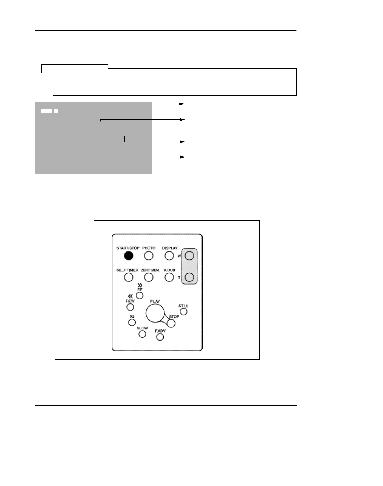
STEP 2
1. Press and hold the "F.ADV" button on the
remote control and "ENTER" button on the
video camera at the same time for more than 10
seconds.
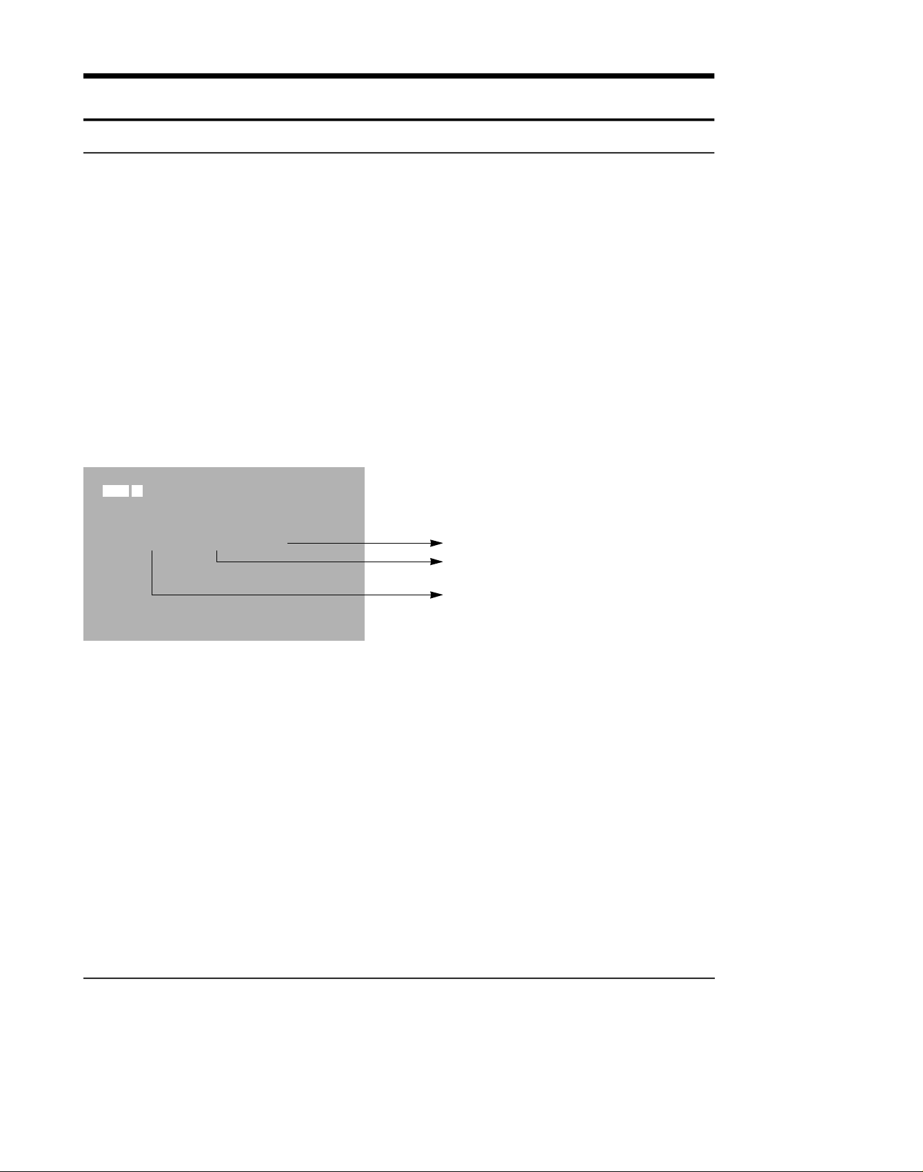
2. When monitor OSD appears as shown below,
VCR adjustment mode has been activated successfully.
3. When changing the adjustment item after the
adjusted value is designated, press the
"START/STOP" button.
Indicates preset values
Indicates the adjusted values
Indicates current adjustment item.
Samsung Electronics 3-1
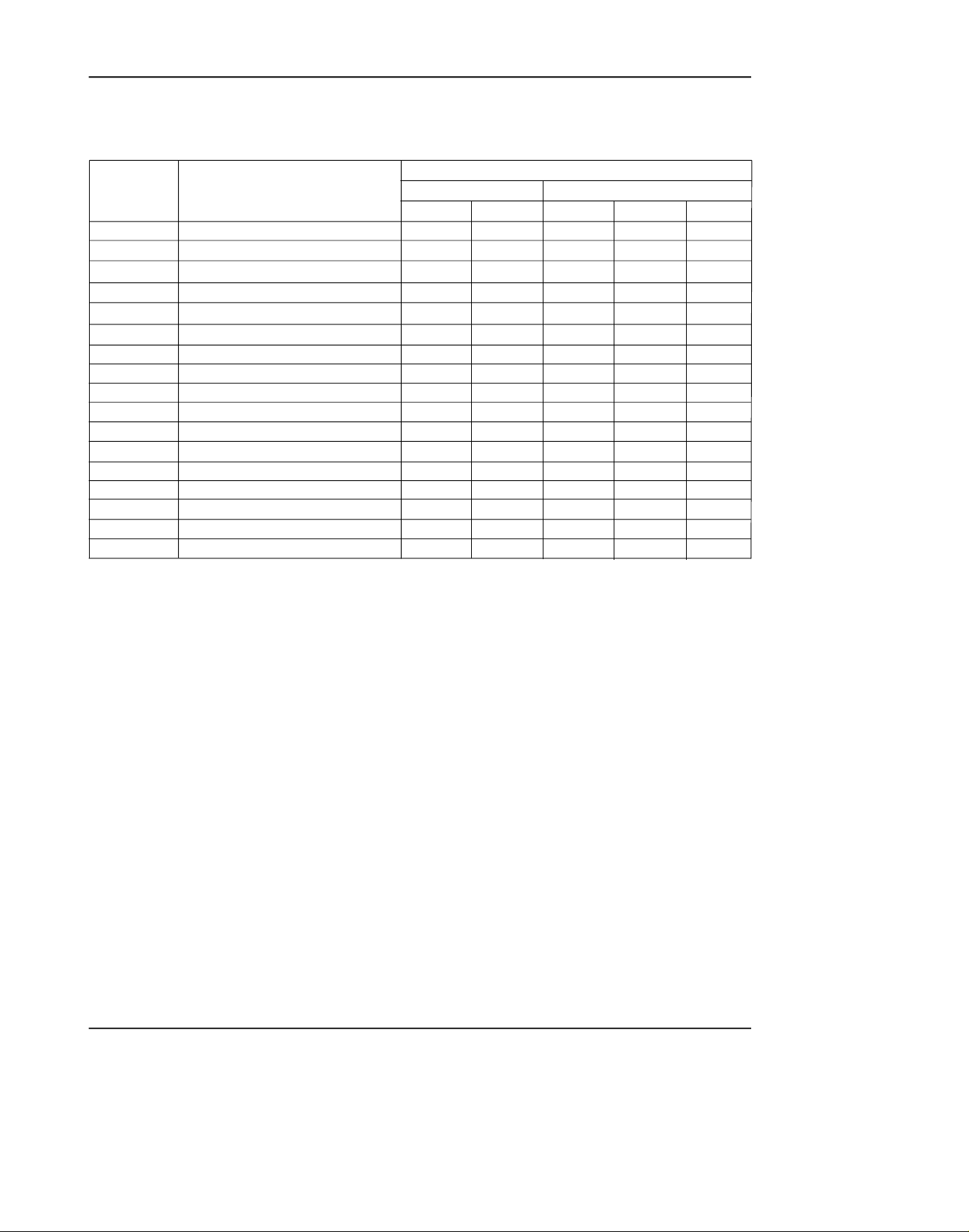
Page 2
Adjustment and Adjustment
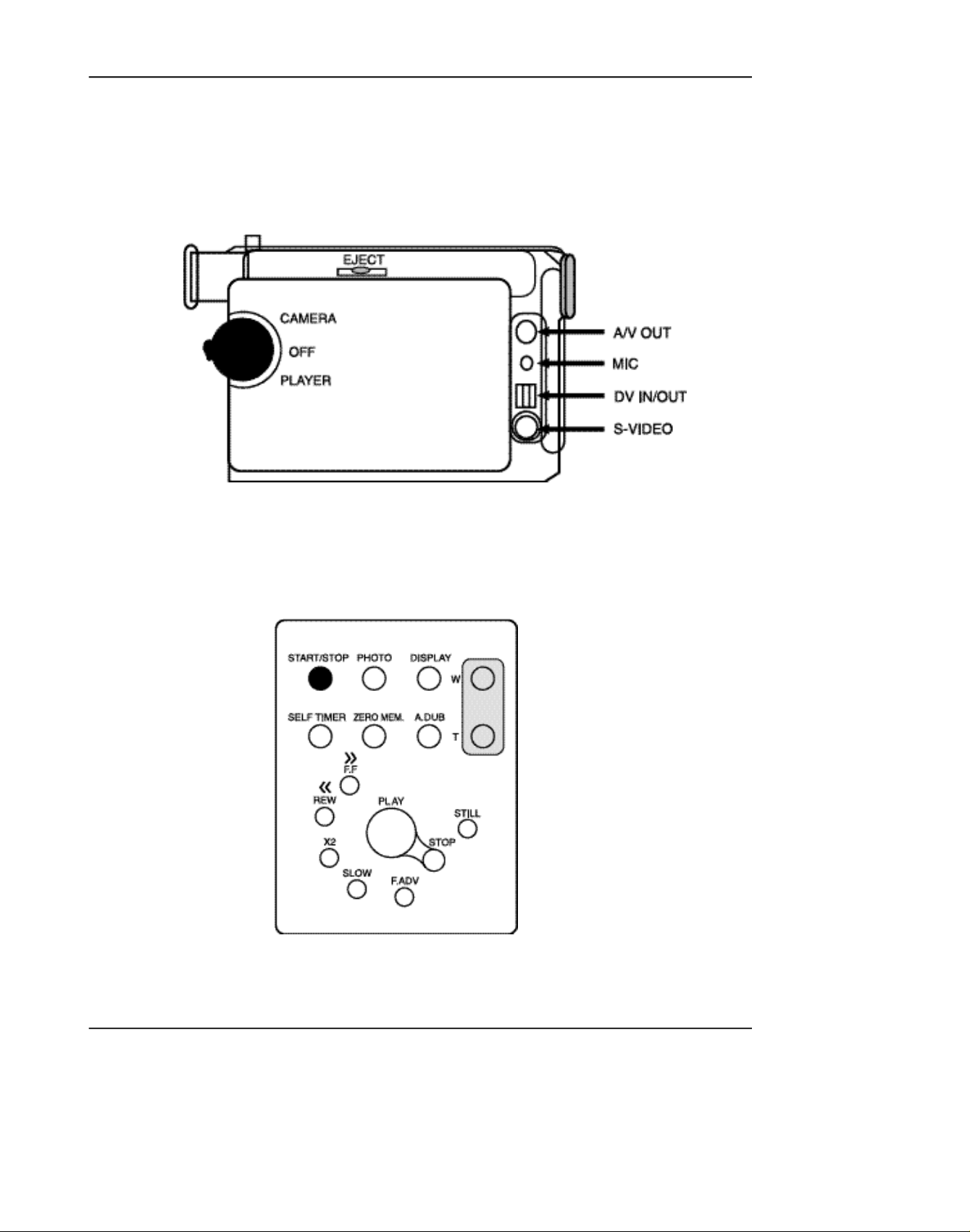
Fig.1. RIGHT CASE
Fig.2. REMOCON KEY
STEP 3 . If you want to finish the adjustment mode, you have to do Power Reset.
The Power Reset means that you pull out the power source and pull in it again.
Samsung Electronics3-2
Page 3
Adjustment and Adjustment
3-1-2. VCR Adjustment
1. VCR Adjustment Items
Items DescriptionAdj. value
V-REF Adjustment Video reference
EXTRA 7D Audio VCO PLL
RECCUR 80 REC current
A-REF1 80 Audio 48KHz mode
A-REF2 80 Audio 44.1KHz mode
A-REF3 80 Audio 32KHz mode
HDSWP Adjustment Head Adjust switch
ZOOMVR Adjustment Adjust center value in the ZOOM switch
OPTION
DUBCUR 80
MODEL OPTION RESERVED(fixed value)
DUB REC CURRENT
* MODEL OPTION
Model Adj.value
VP-D73 C2
VP-D75i / SCD75 CE
SCD73 / VP-D73i C6
VP-D75 CA
VP-D76 / VP-D77 D2
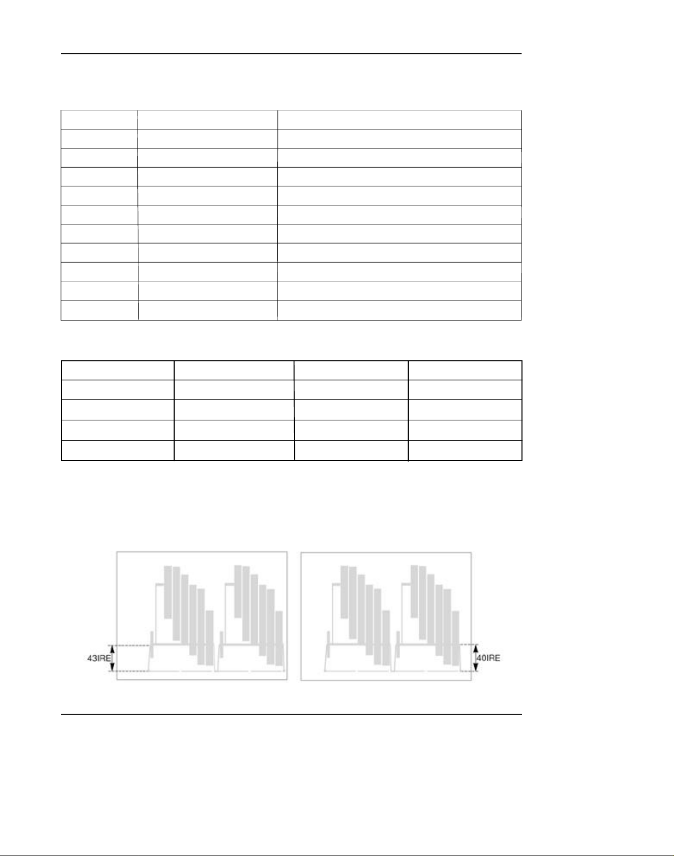
2. How to adjust Video-Reference (V-REF).
1) Connect video output cable to wave form scope. The wave form scope must be connected to monitor.
(75Ω termination)
2) Set to the VCR adjustment mode.
3) Adjust VREF so that SYNC level of video output signal is PAL(43 IRE) and NTSC(40 IRE).
Model Adj.value
VP-D76i D6
VP-D77i D6
SC-D77 D6
PAL NTSC
Samsung Electronics 3-3
Page 4
Adjustment and Adjustment
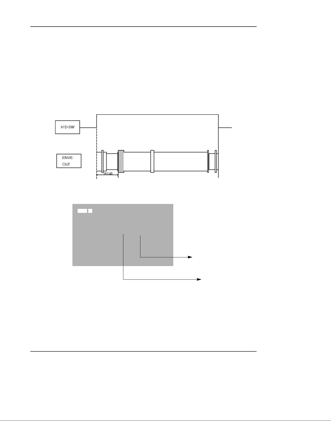
3. How to adjust Head Switching (HDSWP)
1) Connect No. 2 pin of WAFER CNR02 (HEAD-SW signal) for adjustment to CH1 of oscilloscope.
2) Connect No. 3 pin of WAFER CNR02 (ENVE-OUT signal) for adjustment to CH2 of oscilloscope.
3) Play standard tape.
4) Select HDSW of the video adjustment mode.
5) Adjust so that the time between HEAD-SW START and G1 START OF ENVE-OUT is 141µs (±10µs).
G1
4. Center Value Adjustment of Zoom Switch
SP PLAY
0:00:00:00
NO MODE EVR EPR
1
ZOOMVR
80H 80H
S64 LOO
(Preset value of the Zoom SW)
(Adjusted value of the
Zoom SW)
1) Select ZOOMVR in the video adjustment mode.
2) Adjust ZOOM SW so that the switch is put in the middle of T and W.
3) Adjust ZOOMVR so that the current value of ZOOM SW is equal to the adjusted ZOOMVR value.
Samsung Electronics3-4
Page 5
3-1-3. PRML Adjustment Preparation
1. How to set up PRMLAdjustment Mode
PRML Adjustment Setup
1. Press the Display button in VCR adjustment mode.
2. When monitor OSD appears as shown below, PRML adjustment mode has been activated
successfully.
Adjustment and Adjustment
MODE REG PRML EPR
PLAY O OCO OCO
S64 LOO
2. Remote Control Button Location
Remote Control
SP PLAY
Indicates address of adjusting item
by using from 00 to 24.
Indicates operating mode of PRML.
Indicates preset values.
Indicates the adjusted values.
3. Press the Address selection button(START/STOPbutton) to skip the next address in order to finish the
adjustment and store data. After finishing the adjustment, you have to do power reset.
The PRML BER will be set to the right adjustment when shipping out video camera and PCB ASSY from
*
factory.
Samsung Electronics 3-5
Page 6
Adjustment and Adjustment
3-1-4. PRML Adjustment
1. How to set up PRMLAdjustment Mode
Address Name
00
01
02
03
04
05
06
07
08
09
0A
0B
0C
0D
0E
0F
24
PGC/SQPI/FIRO
IDO/DOD/ATFAQ/FIR4
GDH0/FIR1H0
GDH1/FIR1H1
L P G C / D AT F / P G C E N / T D O I / F I R 3 H 0
BPGC/FCLP/FIR3H1
LTG/LPGC/BPLG/TC13/TC2/FIR2
AT F F C / D O H G / AT F H G / H G S E L / S L E E P
D D O S C / S E F T H / D L Z I / TA D A P T / V I T
ATFSEL/SYMC/DAMP
EZCNT/LPFBYP/PDTST/...
HLD/FCHO/BSTH0
CMXEN/FCH1/BSTH1
ATGH0/DOGCH0/TP1SEL
ATGCH1/DOGCH1/TSEL
FRQ/RLZSEL/...
AE/DZ/INTL/.../TWR
PB
0C0
0 0 0
3 0 0
3 0 0
4 0 0
6 0 0
8 0 5
#0 0
2 1 E
2 2 3
0 0 4
2 2 A
22A
F 6 5
8 6 0
0 0 F
FA 2
SP
SEARCH/SLOW
0C0
0 0 0
3 0 0
3 0 0
4 0 0
6 0 0
8 0 5
#0 0
A 1 E
2 2 3
0 0 4
2 8 A
2 8 A
8 6 5
8 6 0
0 0 F
7 A 2
MODE
PB
0C0
0 0 0
7 C 0
7 C 0
4 0 0
5 0 0
8 0 5
#0 0
228
2 2 3
2 C A
2 C A
865
F 6 5
8 6 0
0 0 F
FA F
LP
SEARCH
0C0
0 0 0
7C0
7C0
4 0 0
5 0 0
8 0 5
# C 0
A 2 8
2 2 3
2 0 0
2 8 A
2 8 A
F 5 5
8 5 0
0 0 F
7 A F
VP
SLOW
0C0
0 0 0
7C0
7C0
400
500
805
# 8 0
A28
223
200
28A
28A
F55
850
00F
7AF
2. BER Adjustment Specifications (Reference)
1) Get into the VCR adjustment mode.
;Press and hold the “F.ADV” button on the remote control and “ENTER” button on the video camera
at the same time for more than 10 seconds.
2) Turn offAdaptive. ............................................................................7A2 ;REG24
3) Find out the optional minimum BER value in REG. 12 BOOST.
start values ........................................................................................28A ;REG12
The optimum means the number error is less than 10 EA. ;Current D73/D75/D76/
D77 manufacturing standard
If the minimum value is as the followings, designate as the right values.
Min ........................................................................................................... ;Selection valueless
iess than 18 .......................................................................................18 ;REG12===24A
19 ........................................................................................................19 ;REG12===26A
20 ........................................................................................................20 ;REG12===28A
Samsung Electronics3-6
Page 7

Adjustment and Adjustment
4) Find out the optimally minimum BER value in REG. 11 BOOST.
start values . . . . . . . . . . . . . . . . . . . . . . . . . . . . . . . . . . . . . . . . . . . . .28A ;REG11
The optimum means the number of error is less than 10 EA. ;Current D73/D75/D76/
D77 manufacturing
standard
If the minimum value is as the followings, designate as the right values.
[Add +2 to select the one.]
Min . . . . . . . . . . . . . . . . . . . . . . . . . . . . . . . . . . . . . . . . . . . . . . . . . . ;Selection valueless
less than18 . . . . . . . . . . . . . . . . . . . . . . . . . . . . . . . . . . . . . . . . .18 ;REG11 ===24A
19 . . . . . . . . . . . . . . . . . . . . . . . . . . . . . . . . . . . . . . . . . . . . . . . . .19 ;REG11 ===26A
20 . . . . . . . . . . . . . . . . . . . . . . . . . . . . . . . . . . . . . . . . . . . . . . . . .20 ;REG11 ===28A
21 . . . . . . . . . . . . . . . . . . . . . . . . . . . . . . . . . . . . . . . . . . . . . . . . .21 ;REG11 ===2AA
5) Turn on Adaptive. . . . . . . . . . . . . . . . . . . . . . . . . . . . . . . . . . . . . . . . . . ;REG24 ===FA2
6) Check the value is input to unit correctly.
Samsung Electronics 3-7
Page 8

Adjustment and Adjustment
3-2 Camera Adjustment
Note: How to adjust the camera system.
1) EEPROM stores confirmed adjustment value of each adjustment step.
2) DSP (Digital Signal Process : ICP04-MAIN BOARD) digitalizes the camera signal.
3) When changing IC404-MAIN BOARD of EEPROM, readjust main board. While changing LCD
board- and EVF board- always readjust each part.
Since EEPROM stores confirmed adjustment value of each adjustment step, readjusting must be
performed in order to store the changed data.
4) Adjust the following items after changing LENS ASSY.
a. LENS ZOOM TRACK
b. AUTO HALL
c. AUTO IRIS
5) Adjust the following items after changing EEPROM and MAIN BOARD.
a. LENS ZOOM TRACK
b. AUTO HALL
c. AE TARGET
d. AUTO GAIN CONTROL
e. AUTO IRIS
f. AUTO WHITE BALANCE (indoor)
g. AUTO WHITE BALANCE (outdoor)
3-2-1 Adjustment Preparation
1. Measuring Instrument
1) DC power supply
2) Oscilloscope
3) PALvectorscope, NTSC Vectorscope
4) PALwave form monitor, NTSC wave fonitor
5) PALTV or monitor, NTSC TV or monitor
6) Color bar chart
Gray scale chart
2) Camera Pcb configuration
1) Main PCB
2) CCD PCB
3) EVF PCB
4) LCD PCB
3. Before you start
1) Use the buttons on the remote control when adjusting camera.
2) Press the "START/STOP" button when storing confirmed adjustment value of each adjustment step in
EEPROM.
3) There is a flicker on screen after finishing each adjustment step.
4) To clear the adjustment mode, pull out the power source.
Samsung Electronics3-8
Page 9
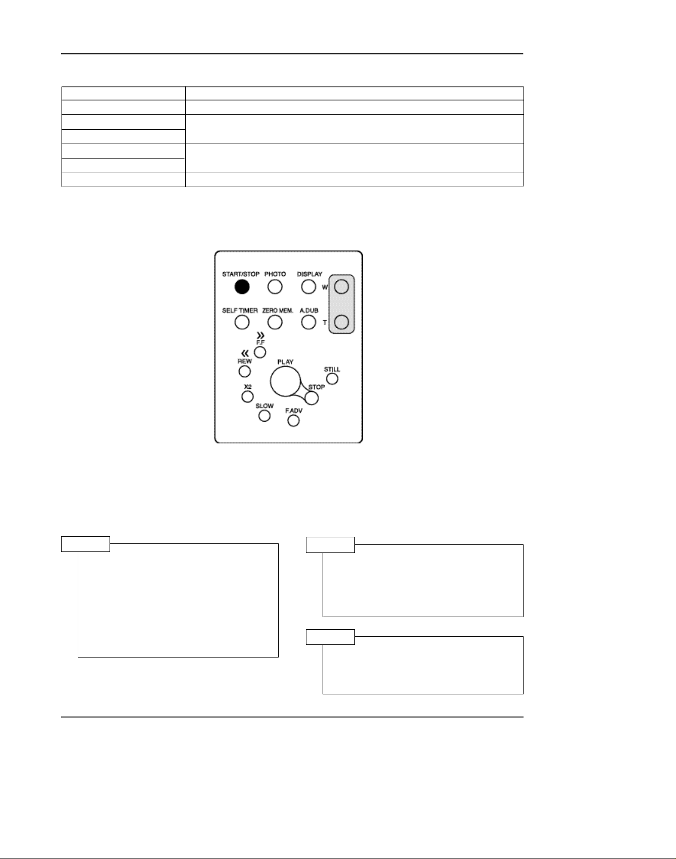
4. Functions of each button on the Remote Control
Adjustment and Adjustment
Button
START/STOP (Confirm)
STOP (Data Down)
PLAY (Data Up)
FF (Mode Up)
REW (Mode Down)
SELF TIMER
In adjustment mode, the buttons of the remote control is as the followings.
Stores changed value in the adjustment and auto adjustment mode.
Changes data in the adjustment state.
Changes mode.
Pre-confirm
Description
Note: In service adjustment mode, button names are different from those in customer function control
mode.
e.g.) "START/STOP" is the same as "Confirm".
5. How to set up the camera adjustment mode
STEP 1
1) Connect the power source
(battery/DC cable).
2) Open Housing from video
camera.
STEP 2
Press and hold the "EDIT(+)" button
and "ENTER" button on the video
camera at the same time for more
than 5 seconds.
3) Set the "POWER(CAMERA/PLAYER)" switch to "CAMERA" position.
STEP 3
4) The OSD appears.
Monitor OSD shows "16D XX XX".
Then camera adjustment mode has
Note : "XX" indicates variable values.
Samsung Electronics 3-9
been activated successfully.
Page 10

Adjustment and Adjustmentnt
Addr. NTSC PAL NAME
0 0 0 H1_INV
1 0 0 HCNT_SET
2 AA 55 H1_DLY
3 23 1 SHP_DLY
4 7A 2A ADCLK_DLY
5 33 33 SHP_WITH
6 A7 A6 V_SKIP
7 0 0 FLD_INV
8 0 0 Hi_SHUT_VAL
9 0 0 Lo_SHUT_VAL
A 8B 8A FCM_Addr_Lo
B 0 0 FCM_Addr_Hi
C 1 0 ITUR601
D 10 10 RG_SEL
E 0 0 DAC0_PIN51
F 0 0 DAC1_PIN52
10 FF FF H_ZM_RATIO
11 4 2 H_ZM_START
12 0 0 H_ZM_SUB
13 0 0 V_ZM_RATIO
14 1 1 V_ZM_SUB_Odd
15 30 37 V_ZM_SKIP
16 0 0 YC_DLY
17 E0 E0 Linear/Spline
18 1 21 UVCLK_INV
19 B5 B5 H_Mirr_Addr
1A 68 68 F_Mirr_Addr
1B C0 0 H_MOSAIC
1C C0 C0 V_MOSAIC
1D 38 38 HSIZE_AUTO_ZM
1E 38 38 VSIZE_AUTO_ZM
1F 0 0 H1_INV
20 10 13 ADCLK_DLY
21 FB FB P_OFFSET
22 10 10 P_THR
23 0 0 P_RAM_Hi
24 0 0 P_RAM_Mdl
25 0 0 P_RAM_Lo
26 20 20 P_FIND_CNT
27 10 E P_WH_START
28 E8 E4 P_WH_END
29 8 8 P_WV_START
2A 77 8E P_WV_END
2B 0 0 P_TEST
2C 0 0 PATTERN_GEN
2D 0 0
2E 0 0
2F 0 0
30 A8 AD YV_APT_BKTH
Samsung Electronics3-10
Page 11

Addr. NTSC PAL NAME
31 E E YH_APT_GN_POSI
32 CE CE YV_APT_GN_POSI
33 4 2 YAPT_NSlice
34 D8 D8 Y_Hi_REF
35 78 78 EDGE_REF
36 E0 E0 YV_APT_LPF_SEL
37 6 6 YAPT_NS_AftGMA
38 F8 F8 YWC
39 7C 7C Y_APT_Clip
3A 62 62 YD_ENH_TH/GAIN
3B B1 A9 YV_APT_GN_NEGA
3C 59 69 YH_APT_GN_NEGA
3D 8F 8F HiFALL/EGFALL
3E 0 0
3F 0 0
40 98 98 Y_GAIN
41 90 90 DSE_Y_GAIN
42 8A 8C C_GAIN
43 0 0 YART
44 C0 C0 YH_PST/EMBO_GN
45 52 52 PSTL_OFFET
46 35 35 EMBO_OFFSET
47 60 60 GRP_DLY
48 0 0
49 0 0
4A 0 0
4B 0 0
4C 0 0
4D 0 0
4E 0 0
4F 0 0
50 A8 A8 DYV_APT_BKTH
51 C C DYHAPT_GN_POSI
52 50 50 DYHAPT_GN_NEGA
53 C C DYVAPT_GN_POSI
54 B0 A0 DYVAPT_GN_NEGA
55 10 10 DY_APT_NSlice
56 70 70 DY_APT_Clip
57 0 0 DYHiLight_GN
58 6 6 DYAPT_NS_GAM
59 62 62 DYDet_EN_TH/GN
5A 10 10 DYVAPT_LPF_SEL
5B 36 36 DWH_START
5C A5 A5 DWH_END
5D 2D 2D DWV_START
5E 7F 7F DWV_END
5F 0 0
60 6 6 S1/S2_SEL
61 46 46 CR_COEF
Adjustment and Adjustment
Samsung Electronics 3-11
Page 12

Adjustment and Adjustment
Addr. NTSC PAL NAME
62 66 66 CB_COEF
63 D C CRDS
64 FC FE CBDS
65 0 0 CGDS
66 0 0 CRCB_WB_Hi
67 33 32 CRWB
68 9D A6 CBWB
69 24 24 CGWB
6A 59 59 CRRG
6B D9 D9 CBRG
6C F2 F2 CRBG
6D 72 72 CBBG
6E 0 0
6F 0 0
70 90 9C C_RY_GP
71 90 90 C_RY_GN
72 12 12 C_RY_HP
73 12 12 C_RY_HN
74 5E 60 C_BY_GP
75 58 5D C_BY_GN
76 17 17 C_BY_HP
77 A A C_BY_HN
78 8 0 C_KEY_Slope1
79 10 0 C_KEY_Slope2
7A 0 0 CKEY_Slpe12_Hi
7B 0 0 C_HUE_FIX
7C 0 0
7D 0 0
7E 0 0
7F 0 0
80 2 2 Y_GAMMA1
81 7 7 Y_GAMMA2
82 12 12 Y_GAMMA3
83 28 28 Y_GAMMA4
84 44 44 Y_GAMMA5
85 68 68 Y_GAMMA6
86 9A 9A Y_GAMMA7
87 EA EA Y_GAMMA8
88 2 2 C_GAMMA1
89 7 7 C_GAMMA2
8A 12 12 C_GAMMA3
8B 28 28 C_GAMMA4
8C 44 44 C_GAMMA5
8D 68 68 C_GAMMA6
8E 9A 9A C_GAMMA7
8F EA EA C_GAMMA8
90 5C 5C AF_W1H_STRT
91 A0 A0 AF_W1H_END
92 27 35 AF_W1V_STRT
3-12 Samsung Electronics
Page 13

Addr. NTSC PAL NAME
93 5F 79 AF_W1V_END
94 14 13 AF_W2H_STRT
95 E4 E3 AF_W2H_END
96 8 9 AF_W2V_STRT
97 76 8E AF_W2V_END
98 14 13 AE_W1H_STRT
99 E4 E3 AE_W1H_END
9A 8 9 AE_W1V_STRT
9B 76 8E AE_W1V_END
9C 48 47 AE_W2H_STRT
9D B0 AF AE_W2H_END
9E 23 2A AE_W2V_STRT
9F 5A 6C AE_W2V_END
A0 17 16 AWB_H_STRT
A1 E7 E6 AWB_H_END
A2 8 9 AWB_V_STRT
A3 76 8E AWB_V_END
A4 FF FF AE_THR_HiGH
A5 0 0 AE_THR_LOW
A6 B0 B0 AWB_THR_HiGH
A7 40 40 AWB_THR_LOW
A8 B0 B0 AF_Clip_THR
A9 F0 F0 AE_Clip_THR
AA 4 4 OZONE_SEL
AB 0 0
AC 0 0
AD 0 0
AE 0 0
AF 0 0
B0 0 0 DIS-DIS ON
B1 98 98 DIS-FRAME
B2 A0 E0 DIS-DVC
B3 0 0 DIS-KX
B4 0 0 DIS-KY
B5 B2 B2 DIS_SP_H
B6 16 1A DIS_SP_V
B7 C0 C0 DIS_WIDTHL
B8 3 3 DIS_WIDTHH
B9 F2 1F DIS_HEIGHTL
BA 0 1 DIS_HEIGHTH
BB E2 E2 DIS_PIP_HSPL
BC 2 2 DIS_PIP_HSPH
BD 90 A6 DIS_PIP_VSPL
BE 0 0 DIS_PIP_VSPH
BF B6 DE DIS_PBOX_HSPL
C0 2 2 DIS_PBOX_HSPH
C1 AE CF DIS_PBOX_VSPL
C2 0 0 DIS_PBOX_VSPH
C3 20 20 DIS_PIP_DSP_HADJ
C4 2 2 DIS_PIP_DSP_VADJ
Adjustment and Adjustment
Samsung Electronics
3-13
Page 14

Adjustment and Adjustment
Addr. NTSC PAL NAME
C5 20 22 DIS_PBOX_DSP_HADJ
C6 1 2 DIS_PBOX_DSP_VADJ
C7 9B 9B DIS_OUT_OFF
C8 9B 9B DIS_OUT_OFF1
C9 B5 B5 DIS_GR_MODE
CA A C DIS_CLK2_SEL
CB A0 C0 DIS_SIS2_SEL0
CC 25 24 DIS_OSD_SEL
CD 0 0 DIS_PIP_SIS2_SEL
CE 1E 1E DIS_DCLP_R
CF 24 24 DIS_DCLP_F
D0 4 4 DIS_YHAFS
D1 C0 80 DIS_APCLP
D2 8 6 DIS_APSC
D3 0 0 DIS_ECST
D4 0 0 DIS_ECSG
D5 83 83 DIS_G1
D6 8F 8D DIS_G0
D7 0 0 DIS_HUE1_OFF
D8 0 0 DIS_ECHUE1
D9 0 0 DIS_ECHUE2
DA 10 10 DIS_APSCV
DB F0 F0 DIS_WV1
DC 90 90 DIS_WH1
DD 4 4 DIS_OVERLAY
DE 0 0 DIS_T0
DF 10 10 DIS_MAN_T0
E0 2 2 DIS_TIIR_TH
E1 0 0 DIS_LINEAR
E2 0 0 DIS_GA0
E3 8 8 DIS_GA1
E4 10 10 DIS_GA2
E5 18 18 DIS_GA3
E6 20 20 DIS-GA4
E7 30 30 DIS_GA5
E8 40 40 DIS_GA6
E9 60 60 DIS_GA7
EA 7F 7F DIS_GA8
EB 0 0 DIS_GB0
EC 8 8 DIS_GB1
ED 10 10 DIS_GB2
EE 18 18 DIS_GB3
EF 20 20 DIS_GB4
F0 30 30 DIS_GB5
F1 40 40 DIS_GB6
F2 60 60 DIS_GB7
F3 7F 7F DIS_GB8
F4 60 60 DIS_SP_HM
F5 16 1A DIS_SP_VM
F6 DC 7 DIS_HEIGHTML
3-14
Samsung Electronics
Page 15

Addr. NTSC PAL NAME
F7 0 1 DIS_HEIGHTMH
F8 0 0 DIS_WIDTHML
F9 3 3 DIS_WIDTHMH
FA FB FB DIS_KXMD
FB FB FB DIS_KYMD
FC F7 F7 DIS_OSD_MODE
FD C1 C1 DIS_DIS_ENX
FE 0 0 DIS_OXL
FF 0 0 DIS_OXH
100 0 0 DIS_OY
101 0 0 DIS_CX
102 0 0 DIS_CY
103 41 22 DIS_AX/AY
104 33 33 DIS_AUTO_CENT
105 88 88 DIS_VGGAINX
106 21 21 DIS_VGSTEP
107 48 48 DIS_THR_SEL
108 11 11 DIS_CXY_BIAS
109 A5 A5 DIS_MATCHX_EN
10A A5 A5 DIS_MATCHY_EN
10B 68 68 DIS_SHMFBC
10C E0 E0 DIS_MVIIR_EN
10D 24 24 DIS_OZNSEL
10E 73 89 DIS_OAEVE_WB
10F 1D 21 DIS_OAEVS_WB
110 D4 D6 DIS_OAEHE_WB
111 26 2A DIS_OAEHS_WB
112 61 70 DIS_OAEVE_WA
113 1C 25 DIS_OAEVS_WA
114 B1 B3 DIS_OAEHE_WA
115 4B 4F DIS_OAEHS_WA
116 5F 79 DIS_OAFVE_W2
117 27 35 DIS_OAFVS_W2
118 A0 A0 DIS_OAFHE_W2
119 5C 5C DIS_OAFHS_W2
11A 74 8A DIS_OAFVE_W1
11B 5 3 DIS_OAFVS_W1
11C C8 C8 DIS_OAFHE_W1
11D 2C 2C DIS_OAFHS_W1
11E 0 0 DIS_OYL_TH
11F FF FF DIS_OYH_TH
120 A8 80 DIS_OAECLIP_TH
121 B0 E8 DIS_OAFCLIP_TH
122 0 0 DIS_PFCNT_M1
123 10 10 DIS_PTHRESH
124 0 0 DIS_POFFSET
125 3 3 DIS_PCMD
126 0 0 DIS_PRAMIL
127 0 0 DIS_PRAMIM
128 0 0 DIS_PRAMIH
Adjustment and Adjustment
Samsung Electronics
3-15
Page 16

Adjustment and Adjustment
Addr. NTSC PAL NAME
129 0 0 DIS_PRAMA_M1
12A 0 0
12B 0 0
12C 0 0
12D 0 0
12E 0 0
12F 0 0
130 0 0 CDS_CONTROL1H
131 0 0 CDS_CONTROL1L
132 0 0 CDS_AGCH
133 85 85 CDS_AGCL
134 0 0 CDS_HALL_GAINH
135 25 25 CDS_HALL_GAINL
136 0 0 CDS_HALL_REFH
137 C8 C8 CDS_HALL_REFL
138 0 0 CDS_COARSE_OFFSETH
139 0 0 CDS_COARSE_OFFSETL
13A 0 0 CDS_FINE_OFFSETH
13B 0 0 CDS_FINE_OFFSETL
13C 0 0 CDS_VBH
13D 0 0 CDS_VBL
13E 0 0 CDS_OPTBLACKH
13F 4 4 CDS_OPTBLACKL
140 0 0 CDS_HOT_PIXELH
141 1 1 CDS_HOT_PIXELL
142 0 0 CDS_COLD_PIXELH
143 0 0 CDS_COLD_PIXELL
144 0 0 CDS_CONTROL2H
145 4 4 CDS_CONTROL2L
146 0 0 CDS_BLANKH
147 0 0 CDS_BLANKL
148 0 0 CDS_DLY1_ADCLKH
149 8 0 CDS_DLY1_ADCLKL
14A 0 0 CDS_DLY2_SV_SRH
14B 22 1 CDS_DLY2_SV_SRL
14C 1 1 CDS_TESTH
14D 80 80 CDS_TESTL
14E 0 0
14F 0 0
150 0 0 MOTOR_HEADER
151 18 18 MOTOR_STARTTIME
152 1 1 MOTOR_DRIVETIME
153 8 8 MOTOR_CHOPPING
154 40 40 MOTOR_EXTPIN
155 44 44 MOTOR_EVRA
156 44 44 MOTOR_EVRB
157 0 0 MOTOR_CHECKSUM
158 0 0
159 0 0
15A 0 0
Samsung Electronics3-16
Page 17

Adjustment and Adjustment
Addr. NTSC PAL NAME
15B 0 0
15C 0 0
15D 0 0
15E 0 0
15F 0 0
160 80 88 D_EEP_IRISCONH
161 FF FF D_EEP_IRISCONL
162 7E 87 EEP_ae_iris95ire
163 2A 36 D_EEP_ae_target
164 14 18 D_EEP_ae_blc_target
165 20 20 D_EEP_ae_hallmin
166 DC F4 D_EEP_ae_hallmax
167 53 58 D_EEP_ae_irismin
168 D6 E6 D_EEP_ae_irismax
169 22 22 D_EEP_ae_agcmin
16A 72 72 D_EEP_ae_agcmax
16B 10 10 D_EEP_ae_hallgainstr
16C A4 A4 D_EEP_ae_halldiftar
16D 40 40 D_EEP_ae_agcmaptarget
16E 38 38 D_EEP_ae_tarpecnt
16F 20 22 BLC_target_percent
170 30 30 AE_clp_tar_ratio
171 1 1 AE_clp_tar_decmax
172 38 38 D_EEP_ae_startagc
173 CC CC D_EEP_ae_end_hvcore
174 55 44 D_EEP_ae_end_hgain
175 84 84 D_EEP_ae_end_vgain
176 10 18 D_EEP_ae_end_slice
177 2C 29 D_EEP_ae_csuppress
178 48 48 Iris_value(afhall)
179 90 90 AE_Hall_Adj
17A 14 14 AE_tar_marginsht
17B 6 6 AE_tar_margin
17C F F AE_agcupstr
17D 2 2 AE_agcupamount
17E 8 8 DSP P_OFFSET cont
17F 4 4 EEP_AE_agcupsped
180 8 8 EEP_AE_method
181 0 0 EEP_AE_speed_down1
182 A A Iris control speed
183 5 4 EEP_AE_speed_down2
184 4E 4E EEP_AE_damp_point
185 10 10 shutter control speed
186 10 10 AGC control speed
187 C6 E9 EEP_AE_datamax
188 60 50 EEP_AE_BLC_datamax
189 7 7 AE_adjtarh
18A C1 C1 YV_APT_GN_NEGA
18B 69 71 YH_APT_GN_NEGA
18C AD AC D_EEP_ae_end_hvcore
Samsung Electronics 3-17
Page 18

Adjustment and Adjustment
Addr. NTSC PAL NAME
18D 0 0 D_DSP_POFFSET_TEST
18E A0 A0 D_EEP_AE_haldifmin
18F 5 5 Tele_AE_Target
190 9F A1 D_EEP_awb_b_3100
191 33 31 D_EEP_awb_r_3100
192 54 54 D_EEP_awb_b_5100
193 51 4F D_EEP_awb_r_5100
194 A0 A6 AWB_3100_B_maxclip
195 83 82 AWB_5100_R_maxclip
196 88 88 AWB_tracking
197 53 56 EEP_awb_hall_outdoor
198 EC EC D_EEP_awb_margin_right
199 21 21 WB_BR_Slop
19A 3 0 D_EEP_awb_b_start
19B 82 0 D_EEP_awb_r_start
19C 8A 8A awb_b_gain_pecnt
19D 84 83 awb_r_gain_pecnt
19E 12 12 awb_rhuen_5100
19F 12 6 awb_rhuep_5100
1A0 12 C awb_bhuen_5100
1A1 28 20 awb_bhuep_5100
1A2 E E WB_Left_margin
1A3 6 4 WB_Right_margin
1A4 76 76 WB_detect_ratio
1A5 20 20 WB tracking speed
1A6 19 19 AWB_3100_R_contup_slop
1A7 60 60 WB_Adj_start
1A8 60 60 WB_Adj_clip
1A9 5E 76 WB_STOP_Release
1AA A A D_EEP_AWB_y_divide
1AB 2 2 D_EEP_awb_b3100_move
1AC 0 0 D_EEP_awb_r3100_move
1AD 2 81 D_EEP_awb_b5100_move
1AE 2 2 D_EEP_awb_r5100_move
1AF 30 30 D_EEP_awb_stable_threshold
1B0 17 17 D_EEP_ZPHOTOH
1B1 30 12 D_EEP_ZPHOTOL
1B2 11 11 D_EEP_FPHOTOH
1B3 7D 7C D_EEP_FPHOTOL
1B4 FF FF D_EEP_FTELEERRH
1B5 F3 EA D_EEP_FTELEERRL
1B6 0 0 D_EEP_FWIDEERRH
1B7 1B 24 D_EEP_FWIDEERRL
1B8 9 9 D_EEP_ztzzver
1B9 80 80 D_EEP_af_top_thr
1BA 7F 7F EEP_zmacro
1BB 5A 5A EEP_ztrack_hall
1BC 18 18 AF_Low_ratio
1BD D D EEP_AF_fend_bound
1BE CA 8A D_Mask_AF_Option
Samsung Electronics3-18
Page 19

Adjustment and Adjustment
Addr. NTSC PAL NAME
1BF 54 54 AF_ZigZag_threshold
1C0 A A AF_Top_threshold
1C1 4 4 AF_noise cutoff
1C2 18 18 AF clip data threshold
1C3 1 1 Zoom track version
1C4 20 30 ZTrack_iris_max/min
1C5 12 12 AF_Ratio_min
1C6 1E 1E AF_Top_threshold
1C7 8 8 ZTrack_hysterysis
1C8 C C EEP_AF_spot_thr
1C9 3 3 EEP_AF_peak_judge
1CA 6 6 Lens_Adj_threshold
1CB 0 0 D_EEP_f4perrh
1CC 0 0 D_EEP_f4perrl
1CD 0 0 D_EEP_zoomhigh
1CE 40 40 D_EEP_macroarea
1CF 40 40 D_EEP_zzlongthres
1D0 77 90 D_EEP_wt_ve
1D1 3 5 D_EEP_wt_vs
1D2 C4 C4 D_EEP_wt_he
1D3 18 1C D_EEP_wt_hs
1D4 70 70 D_EEP_wt_agc
1D5 4 4 D_EEP_wt__repeat
1D6 10 10 D_EEP_wt_poffset
1D7 1 1 D_EEP_CDS_weight
1D8 6 6 D_EEP_awbhalleff1
1D9 1 1 D_EEP_awbhalleff2
1DA 10 10 D_EEP_awbhlength
1DB 6 2 D_EEP_awb_outclip
1DC 1 1
1DD 0 0
1DE 84 84 D_EEP_ae_agcstart
1DF 28 28 D_EEP_awb_inittime
1E0 D8 D8 DIS_FRAME/STILL(B1π¯¡ˆ)
1E1 A0 C8 DIS_S1S2_SEL0 (CBπ¯¡ˆ)
1E2 0 0 DIS_TO(DEπ¯¡ˆ)
1E3 0 0 DIS_MAN_TO(DFπ¯¡ˆ)
1E4 2 2 DIS_TIIR_TH(E0π¯¡ˆ)
1E5 A0 CC DIS_S1S2_SEL0(CBπ¯¡ˆ)
1E6 5 5 DIS_GR_MODE(C9π¯¡ˆ)
1E7 9B 9B DIS_OUT_OFF(C7π¯¡ˆ)
1E8 98 98 DIS_FRAME/STILL(B1π¯¡ˆ)
1E9 A0 8C DIS_S1S2_SEL0(CBπ¯¡ˆ)
1EA AA AA DIS_TO(DEπ¯¡ˆ)
1EB 0 0 DIS_MAN_TO(DFπ¯¡ˆ)
1EC 0 0 DIS_TIIR_TH(E0π¯¡ˆ)
1ED 91 92 DIS_OUT_OFF1(C8π¯¡ˆ)
1EE 80 88 EEP_LowShut_cb_stil(CB)
1EF 80 88 EEP_LowShut_cb_stop(CB)
1F0 F0 EB D_EEP_dis_dzstr
Samsung Electronics 3-19
Page 20

Adjustment and Adjustment
Addr. NTSC PAL NAME
1F1 D5 D5 D_EEP_dis_dztele
1F2 D4 D4 D_EEP_dis_dzend
1F3 F0 0 D_EEP_dis_wide_dz
1F4 0 0 D_EEP_wide_dz
1F5 0 0 D_EEP_dis_dz(A)
1F6 0 0 D_EEP_dis_dz(B)
1F7 0 0 wide_dz(A)_point
1F8 0 0 wide_dz(B)_point
1F9 0 0 wide_dz(C)_point
1FA 28 28 D_EEP_disdemo_spd
1F5 0 0
1F6 0 0
1F7 0 0
1FE 0 0
1FF 0 0
200 98 98 DIS_FRAME/STILL(B1π¯¡ˆ)
201 0 0 DIS_TO(DEπ¯¡ˆ)
202 80 80 DIS_MAN_TO(DFπ¯¡ˆ)
203 2 2 DIS_TIIR_TH(E0π¯¡ˆ)
204 7 7 D_EEP_dis_agcstop
205 0 0 D_EEP_dis_shten
206 4 4 D_EEP_dis_weight
207 5 5 D_EEP_dis_thresh
208 6 6 DIS_VGGAINX_TELE
209 7 7 DIS_VGGAINX_MIDDLE
20A 3 3 DIS_VGGAINX_WIDE
20B A 10 DIS_V(x)_Criterion_ A
20C 18 20 DIS_V(x)_constant_C
20D 12 12 D_EEP_up_sht_agc
20E 31 31 D_EEP_down_sht_agc
20F 74 74 D_EEP_ae_agcmax_default
210 38 38 DSP_Hzoom_size
211 38 38 DSP_Vzoom_size
212 4 4 DSP_VSKIP_Default
213 0 0 MODE0_PIN38
214 80 80 EEP_Art_43
215 0 0 EEP_Emboss_43
216 5F 5F EEP_Emboss_44
217 48 48 EEP_Emboss_46
218 AA AA EEP_Emboss_50
219 0 0 EEP_Emboss_51
21A 90 90 EEP_Emboss_52
21B 12 12 EEP_Emboss_53
21C 90 90 EEP_Emboss_54
21D F F EEP_Emboss_55
21E BF BF EEP_Emboss_56
21F 10 10 EEP_Emboss_57
220 18 18 EEP_Emboss_58
221 10 10 EEP_Emboss_59
Samsung Electronics3-20
Page 21

Adjustment and Adjustment
Addr. NTSC PAL NAME
222 0 0 EEP_Emboss_5A
223 20 20 EEP_Sepia_63
224 A0 A0 EEP_Sepia_72
225 3 3 D_EEP_still_cgain_n
226 3 3 D_EEP_still_cgain_agc
227 AA 55 D_EEP BW/MAKEUP_2
228 23 1 D_EEP BW/MAKEUP_3
229 7A 2A D_EEP BW/MAKEUP_4
22A A A LShutNORcsuppress
22B 2C 29 Lshutagc_csuppress
22C 74 74 ae_hall_limit_up
22D 68 68 ae_hall_limit_down
22E 2 2 D_EEP_zt_macro_zz
22F 0 0
230 10 10 PI_one move zoom_H
231 0 0 PI_one move zoom_L
232 10 10 PI_one move focus_H
233 0 0 PI_one move focus_L
234 C C PI_lens check zoom 1
235 C C PI_lens check zoom 2
236 20 20 PI_lens check zoom 3
237 30 30 PI_lens check zoom 4
238 20 20 PI_lens check zoom 5
239 20 20 PI_lens check zoom 6
23A 3B 3B PI_R out data
23B 73 73 PI_B out data
23C 92 92 PI_iris out data
23D 0 0 D_EEP_adj_out
23E 8 8 uart_baud
23F 1 0 D_EEP_MODEL
240 0 0 D_EEP_pannel_addrh
241 21 C9 D_EEP_pannel_addrL
242 0 0 D_EEP_data_display
243 0 0
244 0 0 EEPROM Initialize
245 0 0
246 FF FF D_EEP_lensadj_iris2
247 A0 A0 D_EEP_lensadj_iris
248 38 38 D_EEP_IRIS_SPD1
249 50 50 D_EEP_IRIS_SPD2
24A 70 70 D_EEP_IRIS_SPD3
24B 40 40 D_EEP_IRIS_SPD4
24C 38 38 D_EEP_SHUTTUD_SPD1
24D C8 C8 D_EEP_hallrefstart
24E 0 0 program version(M)
24F 0 0 program version(D)
250 A7 A6 D_EEF_LCD_06
251 1 1 D_EEF_LCD_2C
252 FF FF D_EEF_LCD_42
253 26 66 D_EEF_LCD_60
Samsung Electronics 3-21
Page 22

Adjustment and Adjustment
Addr. NTSC PAL NAME
254 40 40 D_EEF_LCD_70
255 40 40 D_EEF_LCD_71
256 F8 F8 D_EEF_LCD_72
257 F8 F8 D_EEF_LCD_73
258 40 40 D_EEF_LCD_74
259 40 40 D_EEF_LCD_75
25A F8 F8 D_EEF_LCD_76
25B F8 F8 D_EEF_LCD_77
25C 3B 3B LCD_CRWB_67
25D 56 56 LCD_CBWB_68
25E 24 24 LCD_CGWB_69
25F 0 0
260 0 0 SET_LENS_ADJ
261 0 0 SET_HALL_ADJ
262 90 90 SET_AE_TARGET_ADJ
263 0 0 SET_AGC_MAX_ADJ
264 0 0 SET_IRIS_ADJ
265 0 0 SET_3100K_ADJ
266 0 0 SET_5100K_ADJ
267 0 0
268 0 0 PI_PROGRAM
269 0 0 PI_PROGRAM
26A 0 0
26B 0 0
26C 0 0
26D 0 0
26E 0 0
26F 0 0
270 30 30 Manual_iris25
271 40 40 Manual_iris26
272 50 50 Manual_iris27
273 60 60 Manual_iris28
274 6C 6C Manual_iris29
275 0 0
276 E9 E9 ZM table control
277 1 5 DIS POWER SAVE
278 10 10
279 0 A0
27A 8 8 D_EEP_right_divid
27B 4 4 D_EEP_left_divid
27C 4 4 D_EEP_clip_threshold
27D E C D_EEP_bover_length
27E 10 10
27F 0 0
280 14 17
281 14 17
282 14 17
283 14 17
284 14 17
285 14 17
Samsung Electronics3-22
Page 23

Addr. NTSC PAL NAME
286 10 12
287 D E
288 A A
289 7 7
28A 4 4
28B 4 4
28C 0 0
28D 0 0
28E 0 0
28F 0 0
Adjustment and Adjustment
Samsung Electronics 3-23
Page 24

Adjustment and Adjustmentt
3-2-2 Camera Adjustment
Note : "XX XX" indicate the previous preset value and adjusted value. Press the START/STOP (Confirm)
button to store the adjusted value.
16D XX
(Adjusted value)
XX
(Stored value)
1. LENS ZOOM TRACK
Caution : For whole zoom range, it shall be in focus. The location of a focus lens is moving depending on
the location of zoom lens. During adjusting, micom measures the focus location from a near dis-
tance to a long.
1) Camera is set to E-E mode.
2) Focus chart photo (the last page of manual)
3) Ensure that camera is left an about 2.5 m distance from a focus chart and the focus of lens is placed vertically. Attach a focus chart to white or gray wall of a flat surface.
4) Connect a video output terminal to a TV.
5) Press the FF(Mode Up)/REW(Mode Down) button so that OSD shows "260 XX XX".
6) Press the START/STOP(Confirm) button. Never impact on the lens when adjusting zoom and focus lens.
There's is a flicker on screen after finishing the adjustment.
2.5m +/-1Cm
3-24 Samsung Electronics
Page 25

Adjustment and Adjustment
2. AUTO HALL
1) Camera mode & 3100˚ K gray scale chart
2) Connect a video output terminal to a TV.
3) Press the FF(Mode Up)/REW(Mode Down) button so that OSD shows "261 XX XX".
4) Press the START/STOP(Confirm) button.
5) Then micom finds out max. Hall value with an
iris opened and min. Hall value with an iris
closed. Store max. and min. value of Hall in 164
and 165 respectively.
6) There's is a flicker on screen after finishing the
adjustment.
3. AE TARGET LEVEL
1) Camera mode & 3100˚ K gray scale chart
2) Connect a video output terminal to a wave form
monitor and a TV.
3) Press the FF(Mode Up)/REW(Mode Down) button so that OSD shows "262 XX XX".
4) Press the SELF TIMER (PRE-CONFIRM) button.
5) Press the PLAY (Data Up)/STOP (Data Down) so
that the signal level is 90IRE.
6) Press the START/STOP(Confirm) button.
7) There's is a flicker on screen after finishing the
adjustment.
4. AUTO GAIN CONTROL
1) Camera mode & 3100˚ K gray scale chart
2) Connect a video output terminal to a wave
form monitor and a TV.
3) Press the FF(Mode Up)/REW(Mode Down)
button so that OSD shows "263 XX XX".
4) Press the START/STOP(Confirm)button. Then
micom finds out the beginning value of AGC
and stores the value in 16A
5) There's is a flicker on screen after finishing the
adjustment.
5. AUTO IRIS LEVEL
1) Camera mode & 3100˚ K gray scale chart
2) Connect a video output terminal to a wave
form monitor and a TV.
3) Press the FF(Mode Up)/REW(Mode Down)
button so that OSD shows "264 XX XX".
4) Press the START/STOP (Confirm) button.
5) Then micom finds out max. Hall value with an
iris opened and min. Hall value with an iris
closed. Store max. and min. value of in 167and
168 respectively.
6) There's is a flicker on screen after finishing the
adjustment.
95IRE
Samsung Electronics
95IRE
3-25
Page 26

Adjustment and Adjustment
6. AUTO WHITE BALANCE (indoor)
1) Camera mode & 3100˚ K/5100˚ K gray scale chart
2) Connect a video output terminal to a vectorscope and a TV.
3) Press the FF(Mode Up)/REW(Mode Down)
button so that OSD shows "265 XX XX".
4) E n s u re that camera picks up image 40µs on
3100˚K gray scale chart precisely and the illumination is 1500-2000 Lux.
5) Press the START/STOP(Confirm) button to
ensure that white spot on a vectorscope is moving in the middle of screen.
6) There's is a flicker on screen after finishing the
adjustment.
7. AUTO WHITE BALANCE (outdoor)
1) Camera mode & 3100˚ K/5100˚ K gray scale chart
2) Connect a video output terminal to a
vectorscope and a TV.
3) Press the FF(Mode Up)/REW(Mode Down)
button so that OSD shows "266 XX XX".
4) Ensure that camera picks up image 40 on 5100
gray scale chart (3100 gray scale chart + C16 fil-
ter) precisely and the illumination is 1500-2000
Lux.
5) Press the START/STOP(Confirm) button to
ensure that white spot on a vectorscope is moving in the middle of screen.
6) There's is a flicker on screen after finishing the
adjustment.
8. R-Y POSITIVE GAIN
1) Camera mode & 3100˚ K gray scale chart
2) Connect a video output terminal to a vec-
torscope and a TV.
3) Press the FF(Mode Up)/REW(Mode Down)
button so that OSD shows "70 XX XX".
4) Ensure that camera picks up image on 3100˚ K
color bar chart precisely and the illumination is
1500-2000 Lux.
5) Press the PLAY (Data Up)/STOP (Data Down)
so that the red level is 70IRE.
6) Press the START/STOP(Confirm) button to
store data.
7) There's is a flicker on screen after finishing the
adjustment.
9. R-Y NEGATIVE GAIN)
1) Camera mode & 3100˚ K gray scale chart
2) Connect a video output terminal to a vec-
torscope and a TV.
3) Press the FF(Mode Up)/REW(Mode Down)
button so that OSD shows "71 XX XX".
4) Ensure that camera picks up image on 3100˚ K
color bar chart precisely and the illumination is
1500-2000 Lux.
5) Press the PLAY (Data Up)/STOP (Data Down)
so that the cyan level is 65IRE.
6) Press the START/STOP(Confirm) button to
store data.
7) There's is a flicker on screen after finishing the
adjustment.
3-26
Samsung Electronics
Page 27

10. B-Y POSITIVE GAIN
1) Camera mode & 3100˚ K gray scale chart
2) Connect a video output terminal to a vectorscope and a TV.
3) Press the FF(Mode Up)/REW(Mode Down)
button so that OSD shows "74XX XX".
4) Ensure that camera picks up image on 3100˚ K
color bar chart precisely and the illumination is
1500-2000 Lux.
5) Press the PLAY (Data Up)/STOP (Data Down)
so that the blue level is 50IRE.
6) Press the START/STOP(Confirm) button to
store data.
7) There's is a flicker on screen after finishing the
adjustment.
11. B-Y NEGATIVE GAIN
Adjustment and Adjustment
12. R-Y POSITIVE HUE
1) Camera mode & 3100˚ K gray scale chart
2) Connect a video output terminal to a vectorscope and a TV.
3) Press the FF(Mode Up)/REW(Mode Down)
button so that OSD shows "72 XX XX".
4) Ensure that camera picks up image on 3100˚ K
color bar chart precisely and the illumination is
1500-2000 Lux.
5) Press the PLAY (Data Up)/STOP (Data Down)
so that the yellow vectors is 165˚ .
6) Press the START/STOP(Confirm) button to
store data.
7) There's is a flicker on screen after finishing the
adjustment.
1) Camera mode & 3100˚ K gray scale chart
2) Connect a video output terminal to a vectorscope and a TV.
3) Press the FF(Mode Up)/REW(Mode Down)
button so that OSD shows "75 XX XX".
4) Ensure that camera picks up image on 3100˚ K
color bar chart precisely and the illumination is
1500-2000 Lux.
5) Press the PLAY (Data Up)/STOP (Data Down)
so that the yellow level is 50IRE.
6) Press the START/STOP(Confirm) button to
store data.
7) There's is a flicker on screen after finishing the
adjustment.
Samsung Electronics
3-27
Page 28

Adjustment and Adjustment
13. R-Y NEGATIVE HUE
1) Camera mode & 3100˚ K gray scale chart
2) Connect a video output terminal to a vectorscope and a TV.
3) Press the FF(Mode Up)/REW(Mode Down)
button so that OSD shows "73 XX XX".
4) Ensure that camera picks up image on 3100˚ K
color bar chart precisely and the illumination is
1500-2000 Lux.
5) Press the PLAY (Data Up)/STOP (Data Down)
so that the blue vector is 346˚ .
6) Press the START/STOP(Confirm) button to
store data.
7) There's is a flicker on screen after finishing the
adjustment.
14. B-Y POSITIVE HUE
1) Camera mode & 3100˚ K gray scale chart
2) Connect a video output terminal to a vectorscope and a TV.
3) Press the FF(Mode Up)/REW(Mode Down)
button so that OSD shows "76 XX XX".
4) Ensure that camera picks up image on 3100˚ K
color bar chart precisely and the illumination is
1500-2000 Lux.
5) Press the PLAY (Data Up)/STOP (Data Down)
so that the cyan vector is 284˚ .
6) Press the START/STOP(Confirm) button to
store data.
7) There's is a flicker on screen after finishing the
adjustment.
15. B-Y NEGATIVE HUE
1) Camera mode & 3100˚ K gray scale chart
2) Connect a video output terminal to a vectorscope and a TV.
3) Press the FF(Mode Up)/REW(Mode Down)
button so that OSD shows "77 XX XX".
4) Ensure that camera picks up image on 3100˚ K
color bar chart precisely and the illumination is
1500-2000 Lux.
5) Press the PLAY (Data Up)/STOP (Data Down)
so that the red vector is 104˚ .
6) Press the START/STOP(Confirm) button to
store data.
7) There's is a flicker on screen after finishing the
adjustment.
3-28 Samsung Electronics
Page 29

Adjustment and Adjustment
3-3. LCD Adjustment
Notes: For LCD adjustment, use the buttons on the video camera and the remote control.
After each adjustment step is completed, OSD shows "OK".
EEPROM(ICL202) stores confirmed adjustment value of each adjustment step.
After finishing the adjustment, turn power off.
1. How to get into the LCD adjust mode.
STEP 1
1. Connect the power source
(battery/DC cable).
2. Set the "CAMERA/PLAYER" switch to
"CAMERA" position.
3. Camera screen and OSD appears.
4. Open housing of the video camera and
remove tape.
Monitor screen
LCD
MODE 1
01
EPR:XX EVR:XX
When monitor OSD shows as above screen, LCD
adjustment mode has been activated successfully.
STEP2
1) Press and hold the "EDIT(+)" button on the
video camere and"SELF TIMER" button on the
remote control at the same time for more than 5
seconds.
2) Press the “DISPLY” button to make color bar
appear.
Note : "XX" indicates variable values.
Remote Control Button Location
2. Functions of each button on the Remote Control
Button
START/STOP (Confirm)
FF (Mode Up)
REW (Mode Down)
PLAY (Data Up)
STOP (Data Down)
Note: In service adjustment mode, button names are different from those in customer function control
mode.
Samsung Electronics
Stores changed value in the adjustment mode.
Shift adjustment address to left.
Shift adjustment address to right.
Up value.
Down value.
Description
3-29
Page 30

Adjustment and Adjustment
3. Adjustment Mode Table
Address
OD
OA
17
11
09
14
18
19
OC
OC
01
02
03
04
06
07
08
OB
OE
OF
10
12
13
15
16
Mode
VCO
VCOM
BRIGHT
R-W/B
G-W/B
B-W/B
BRIGHT MIN
BRIGHT MAX
COLOR MIN
COLOR MAX
MODEL
H POS
V POS
M O D E 2
HD WID
VD POS
HD POS
O S D
S H A R P
TINT
G A M M A
L I M I T
CONT
R BRT
B BRT
PAL
3F
3D
34
67
4F
41
02
02
02
02
78
B9
18
OF
B7
80
B9
80
00
64
B8
70
80
8F
6A
NTSC
3F
3D
34
67
4F
41
02
02
02
02
F8
B9
OA
OF
B7
80
9E
80
00
64
B8
70
80
8F
6A
Remark
VCO ---> Adjust
COM DC-->Adjust
COM GA>Adjust
R-W/B -->Adjust
G-W/B-->Adjust
B-W/B-->Adjust
Brght varification of MIN
direction for USER
Brght varification of MIN
direction for USER
Brght varification of MIN
direction for USER
Brght varification of MIN
direction for USER
fix initial value
fix initial value
fix initial value
fix initial value
fix initial value
fix initial value
fix initial value
fix initial value
fix initial value
fix initial value
fix initial value
fix initial value
fix initial value
fix initial value
fix initial value
The Adjustment sequence is VCO-->VCOM-->BRIGHT-->R-W/B-->G-W/B-->B-W/B
*
4. Location of Adjustment TP
1) VCO
a) TP-HD & EVR
I C
R
VCOM
Note: In LCD adjustment mode, when shorting
"A" of PCB to GND and pressing the
START/STOP button, EEPROM stores confirmed adjustment value.
3-30
B
G
24P
A
b) Connect an Freguency counter to TP-HD
c) Adjust the EVR so that Freguency is
15.734khz (NTSC),15.625khz(PAL)
2) VCOM
a) TP-VCOM & EVR
b) Connect an voltmeter to TP-VCOM.
c) Adjust the EVR so that DC voltage is DC
1.1±0.05 V.
Samsung Electronics
Page 31

3) Brightness
a) TP-VCOM & EVR
b) Connect an oscilloscope probe to TP-
VCOM.
c) Adjust the EVR so that bright level is 4.4±
0.1 Vp-p.
Adjustment and Adjustment
4.4Vp-p
4) R-W/B
a) TP-R & EVR
b) Connect an oscilloscope probe to TP-R.
c) Adjust the EVR so that Sync tip level is 4.2
Vp-p.
5) G-W/B
a) TP-B & EVR
b) Connect an oscilloscope probe to TP-G.
c) Adjust the EVR so that Sync tip level is 4.2
Vp-p.
6) B-W/B
a) TP-B & EVR
b) Connect an oscilloscope probe to TP-B.
c) Adjust the EVR so that Sync tip level is 4.4
Vp-p.
Sync Tip
Level
Samsung Electronics
3-31
Page 32

Adjustment and Adjustmentt
3-5. EVF Adjustment
3-5-1. EVF adjustment Preparation
STEP 1
1) Connect the power source
(battery/DC cable).
2) Set the "POWER(CAMERA/PLAY-
ER)" switch to "CAMERA" position.
LCD
MODE 1
01
EPR:XX EVR:XX
Monitor screen
Note : "XX" indicates variable values.
STEP 2
Press and hold the "EDIT(+)" button
and "SELFTIMER" button on the
video camera at the same time for
more than 5 seconds.
STEP 3
Press the “DISPLY” button to make color bar
appear.
3-5-2. EVF adjustment
1) VIDEO GAIN
a) Connect an oscilloscope probe to
TP-V.
b) Adjust the VRE02 so that A level is
2.5 Vp-p
3-32
Remote Control Button Location
10 PIN CON.
2 PIN CON.
VR
Location of Test Point
Samsung Electronics
Page 33

Adjustment and Adjustment
3-6. CVF Adjustment
Notes : For CVF adjustment, use the buttons on the video camera and the remote control.
After each adjustment step is completed, OSD shows "OK".
EEPROM(ICV02) stores confirmed adjustment value of each adjustment step.
After finishing the adjustment, turn power off.
1. How to get into the CVF adjust mode.
STEP 1
1) Connect the power source
(battery/DC cable).
2) Set the "CAMERA/VCR" switch to "CAMERA" position and LCD is close.
3) Camera screen and OSD appears.
4) Open housing of the video camera and
remove tape.
Monitor screen
STEP 2
1) Press and hold the "EDIT(+)" buttonon the
video camera and "SELF TIMER" button on
the remote control at the same time for
more than 5 seconds.
2) Press the “DISPLAY” button to make color
bar appear.
CVF
PLL
01
EPR:XX EVR:XX
When monitor OSD shows as above screen, CVF
adjustment mode has been activated successfully.
Note : "XX" indicates variable values.
Remote Control Button Location
2. Functions of each button on the Remote Control
Button
START/STOP (Confirm)
FF (Mode Up)
REW (Mode Down)
PLAY (Data Up)
STOP (Data Down)
Note: In service adjustment mode, button names are different from those in customer function control
mode.
Stores changed value in the adjustment mode.
Shift adjustment address to left.
Shift adjustment address to right.
Up value.
Down value.
Description
Samsung Electronics 3-33
Page 34

Adjustment and Adjustment
3. Adjustment Mode Table
Address
01
02
MODE1
H POS
03 V POS
04
06
07
08
MODE2
HD WID
VD POS
HD POS
09 RGB GA
0A
COM DC
0B OSD
0C
0D
0E SHARP
0F
10 GAMMA
11 R WB
12 LIMIT
13 CONT
15 R BRT
16 B BRT
17
COM GA
18 BRIGHT
Mode
GAIN
VCO
TINT
PAL
NTSC
Remark
34 B4 fix initial value
C8
B9
18 OA
OF OF
B7 B7
80 80
B9 9E
C9
3D
80
C9
3D
80
65 65
98
00
84
A4
D2
BO
OO
84
A4
D2
45 45
91 91
75 75
9D 9D
34 34
64 64
fix initial value
fix initial value
fix initial value
fix initial value
fix initial value
fix initial value
fix initial value
fix initial value
fix initial value
fix initial value
fix initial value
fix initial value
fix initial value
fix initial value
fix initial value
fix initial value
fix initial value
fix initial value
fix initial value
fix initial value
fix initial value
Samsung Electronics3-34
 Loading...