

samsung VP-D73, VP-D73i, VP-D75, VP-D75i, VP-D76 Service Manual
...
DIGITAL VIDEO CAMERA
VP-D73/D73i/D75/D75i/D76/D76i/
D77/D77i
SCD73/D75/D77
Manual
SERVICE
For mechanical disassembly and adjustment, refer to the “Mechanical Manual”
(CSM-2000 AD68-00420B).
© Samsung Electronics Co.,Ltd. SEP. 2001
Printed in Korea
AD68-00420E
DIGITAL VIDEO CAMERA
CONTENTS
1. Specifications
2. Disassembly and Reassembly
3. Alignment and Adjustment
4. Exploded View and Parts List
5. Electrical Parts List
6. Wiring Diagram
7. PCB Diagrams
8. Schematic Diagrams
1. Product Specifications and Comparison Chart
1-1 Product Specifications (SCD73 / SCD75/SCD77)
Design and specifications are subject to change without notice.
Operation
SYSTEM
Video signal NTSC standards
Video recording system 2rotary heads,helical scanning system
Audio recording system Rotary heads, PCM system
Usable cassette Digital video tape (6.35mm width): MiniDV cassette
Tape speed SP : approx. 18.81 mm/s LP : approx. 12.56mm/s
Tape Recording time SP : 60 minutes (when using DVM 60)
LP : 90 minutes (when using DVM 60)
FF/REW time Approx. 150 sec. (using DVM60 tape)
Image device CCD (Charge Coupled Device)
Lens F1.6 22x(Optical),500x(Digital)Electronic zoom lens,
Filter diameter ø37
LCD monitor/Viewfinder
Size/dot number 2.5inch/112,320 pixels
LCD monitor Method TFT LCD
Viewfinder 0.24” B/W LCD
CONNECTORS
Video output 1Vp-p (75Ω terminated)
S-Video output Y: 1vp-p,75Ω ,C: 0.286Vp-p, 75Ω
Audio output -7.5dBs (600Ω teminated)
DV input/output 4pin special in/out connector
External mic ø3.5 stereo , -57dBV( with the 600 ohm mic) / at least 5 kohms
GENERAL
Power source DC 8.4V, Lithium lon Battery Pack 7.4V
Power source type Lithium lon Battery Pack,
Power supply (100V~240V)50/60Hz
Power consumption (Recording) 6.5W(LCD), 5.2W(EVF)
Operating temperature 0°C ~ 40°C (32°F ~104°F) -20°C to 60°C (-4°F to 140°F)
Storag temperature -20°C ~ 60°C (-4°F ~140°F)
External dimension Length 158 mm,Height93 mm,Width 87mm
Weight 580g (Except for Lithium lon Battery Pack and tape)
Built-in MIC Omni-direcional stereo condenser microphone
Remote control Indoors: greater than 15m (straight line)
Outdoors:greater than 5m (straight line)
Description
Samsung Electronics 1-1

Product Specifications
1-2 Product Specifications (VP-D73/D73i/D75/D75i/D76/D76i/D77/D77i)
Design and specifications are subject to change without notice.
Operation
SYSTEM
Video signal PAL, CCIR standards
Video recording system 2rotary heads,helical scanning system
Audio recording system Rotary heads, PCM system
Usable cassette Digital video tape (6.35mm width): MiniDV cassette
Tape speed SP : approx. 18.83 mm/s LP : approx. 12.57mm/s
Tape Recording time SP : 60 minutes (when using DVM 60)
LP : 90 minutes (when using DVM 60)
FF/REW time Approx. 150 sec. (using DVM60 tape)
Image device CCD (Charge Coupled Device)
Lens F1.6 22x(Optical),500x(Digital)Electronic zoom lens,
Filter diameter ø37
LCD monitor/Viewfinder
Size/dot number 2.5inch/112,320 pixels
LCD monitor Method TFT LCD
Viewfinder 0.24” B/W LCD (VP-D77/D77i--> 0.24” COLOUR LCD)
CONNECTORS
Video output 1Vp-p (75Ω terminated)
S-Video output Y: 1vp-p,75Ω ,C: 0.286Vp-p, 75Ω
Audio output -7.5dBs (600Ω teminated)
DV input/output Out only
External mic ø3.5 stereo, -57dBV( with the 600 ohm mic) / at least 5 kohms
GENERAL
Power source DC 8.4V, Lithium lon Battery Pack 7.4V
Power source type Lithium lon Battery Pack,
Power supply (100V~240V)50/60Hz
Power consumption (Rec.) 6.5W (LCD), 5.2W (EVF/CVF)
Operating temperature 0°C ~ 40°C (32°F ~104°F) -20°C to 60°C (-4°F to 140°F)
Storag temperature -20°C ~ 60°C (-4°F ~140°F)
External dimension Length 158 mm,Height93 mm,Width 87mm
Weight 580g (Except for Lithium lon Battery Pack and tape)
Built-in MIC Omni-direcional stereo condenser microphone
Remote control Indoors: greater than 15m (straight line)
Outdoors:greater than 5m (straight line)
Description
1-2
Samsung Electronics
1-3 Comparison Chart
MODEL V.FINDER D.ZOOM DSC CCD DV IN/OUT
SCD73 EVF X500 - 680K IN/OUT
SCD75 EVF X500 4M FLASH 680K IN/OUT
SCD77 EVF X500 8M SMC 680K IN/OUT
VP-D73 EVF X500 - 800K OUT
VP-D73i EVF X500 - 800K IN/OUT
VP-D75 EVF X500 4M FLASH 800K OUT
VP-D75i EVF X500 4M FLASH 800K IN/OUT
Product Specifications
VP-D76 EVF X500 8M SMC 800K OUT
VP-D76i EVF X500 8M SMC 800K IN/OUT
VP-D77 CVF X500 8M SMC 800K OUT
VP-D77i CVF X500 8M SMC 800K IN/OUT
Samsung Electronics 1-3

Product Specifications
MEMO
1-4
Samsung Electronics
2. Disassembly and Reassembly
2-1 Cabinet and PCB
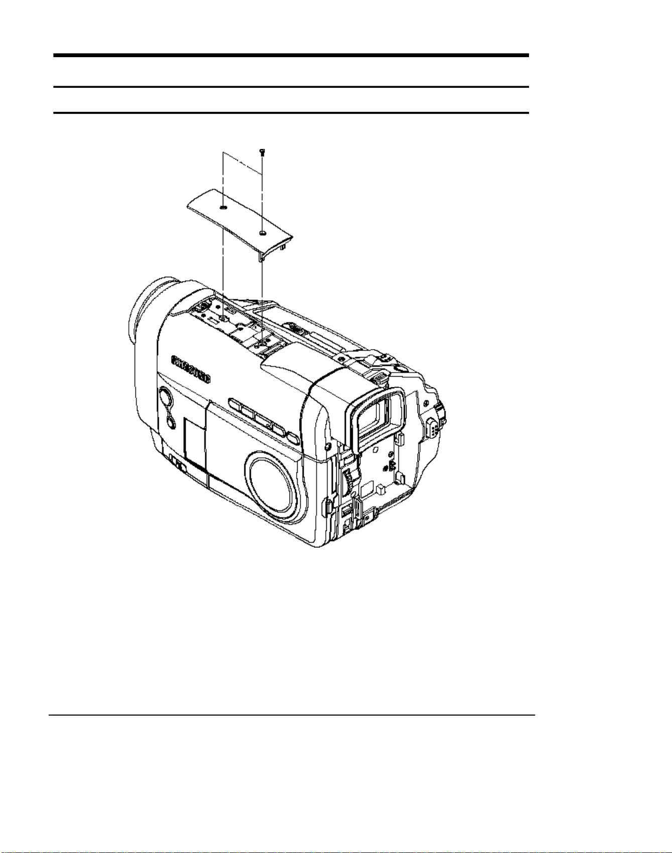
2-1-1 Top Cover removal
(1) Remove 2 screws
Samsung Electronics
Fig. 2-1 Top Cover removal
2-1
Disassembly and Reassembly
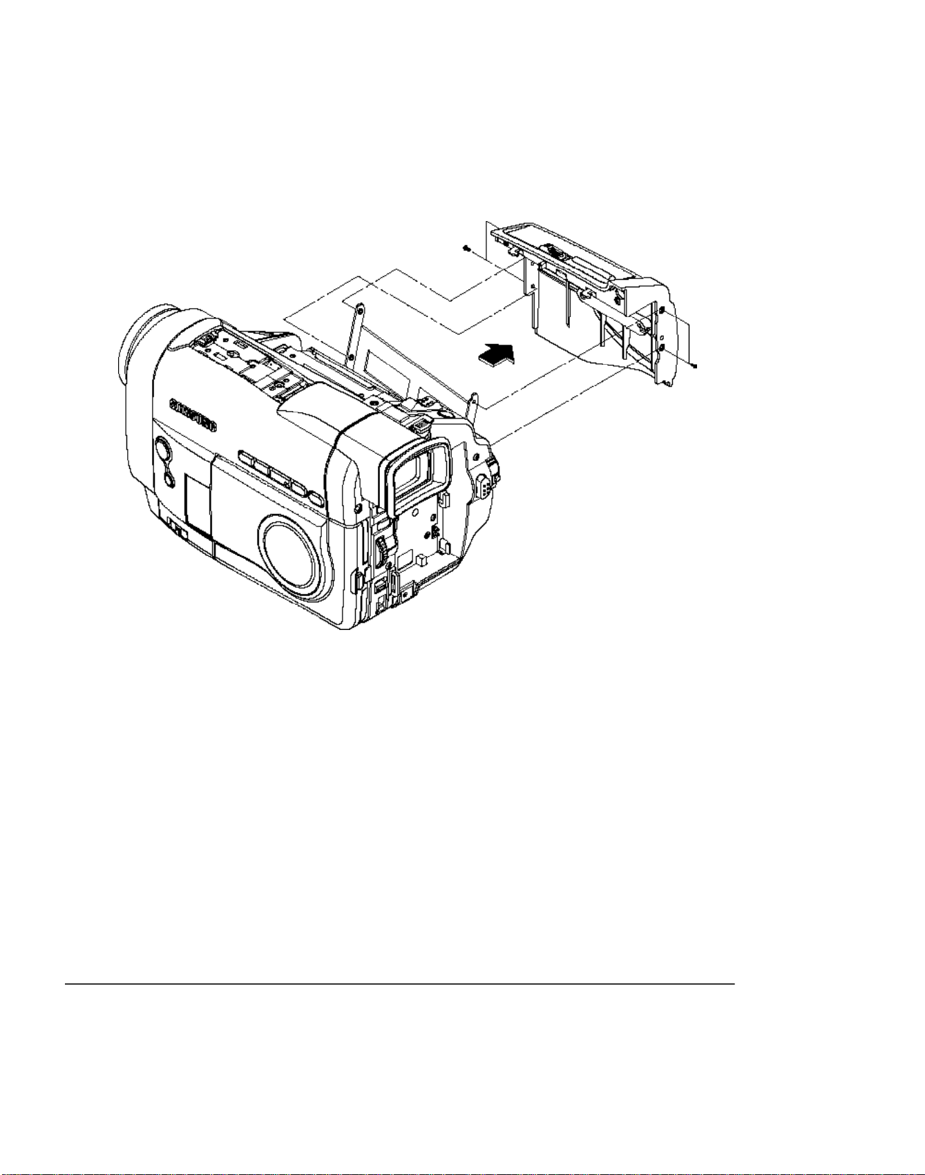
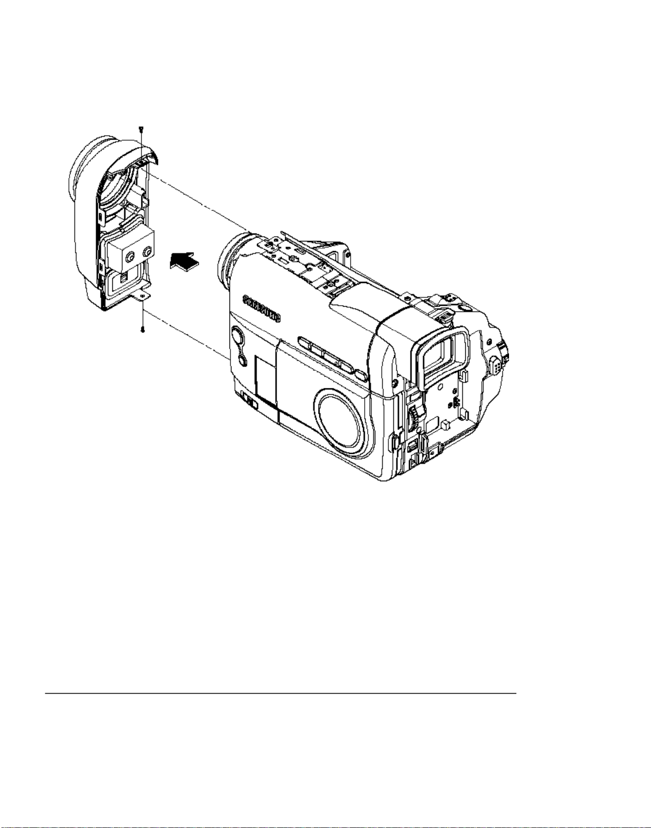
2-1-2 Ass’y Cover Housing removal
(3) Remove cover housing
in the direction of arrow
(1) Remove 2 screws
(2) Remove 2 screws
2-2
Fig. 2-2 Ass’y Cover Housing removal
Samsung Electronics
2-1-3 Ass’y Front removal
(1) Remove 1 screw
Disassembly and Reassembly
(3) Remove ass’y front in the direction of arrow
(2) Remove 1 screw
Fig. 2-3 Ass’y Front removal
Samsung Electronics
2-3
Disassembly and Reassembly
2-1-4 Ass’y Case-Left removal
(1) Remove 2 screws
(2) Remove 2 screws
(5) Remove ass’y case left
in the direction of arrow
(4) Remove 2 screws
Fig. 2-4 Ass’y Case-Left removal
2-4 Samsung Electronics
2-1-5 Ass’y Case-Right removal
(4) Remove ass’y case right
in the direction of arrow
Disassembly and Reassembly
(1) Remove 2 screws
(2) Remove 2 screws
(3) Remove 1 screw
Fig. 2-5 Ass’y Case-Right removal
Samsung Electronics 2-5
Disassembly and Reassembly
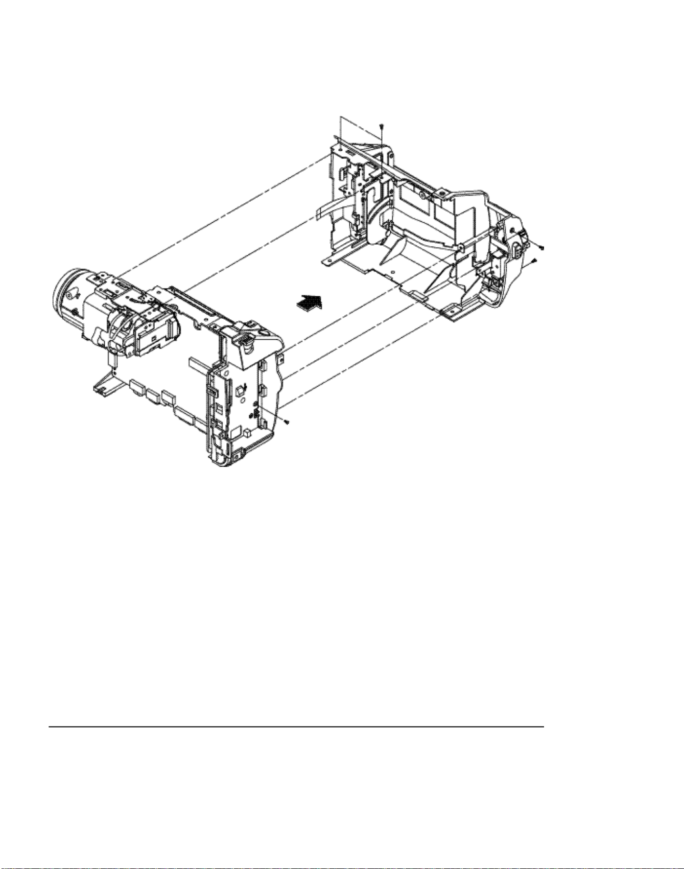
2-1-6 Ass’y Rear removal
(2) Remove ass’y rear
in the direction of arrow
(1) Remove 2 screws
Fig. 2-6 Ass’y Rear removal
2-6 Samsung Electronics
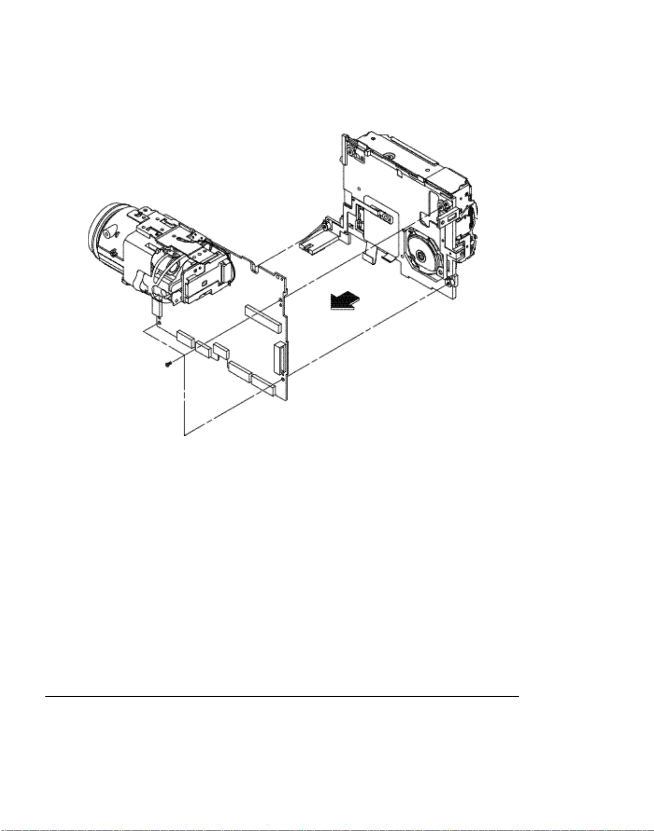
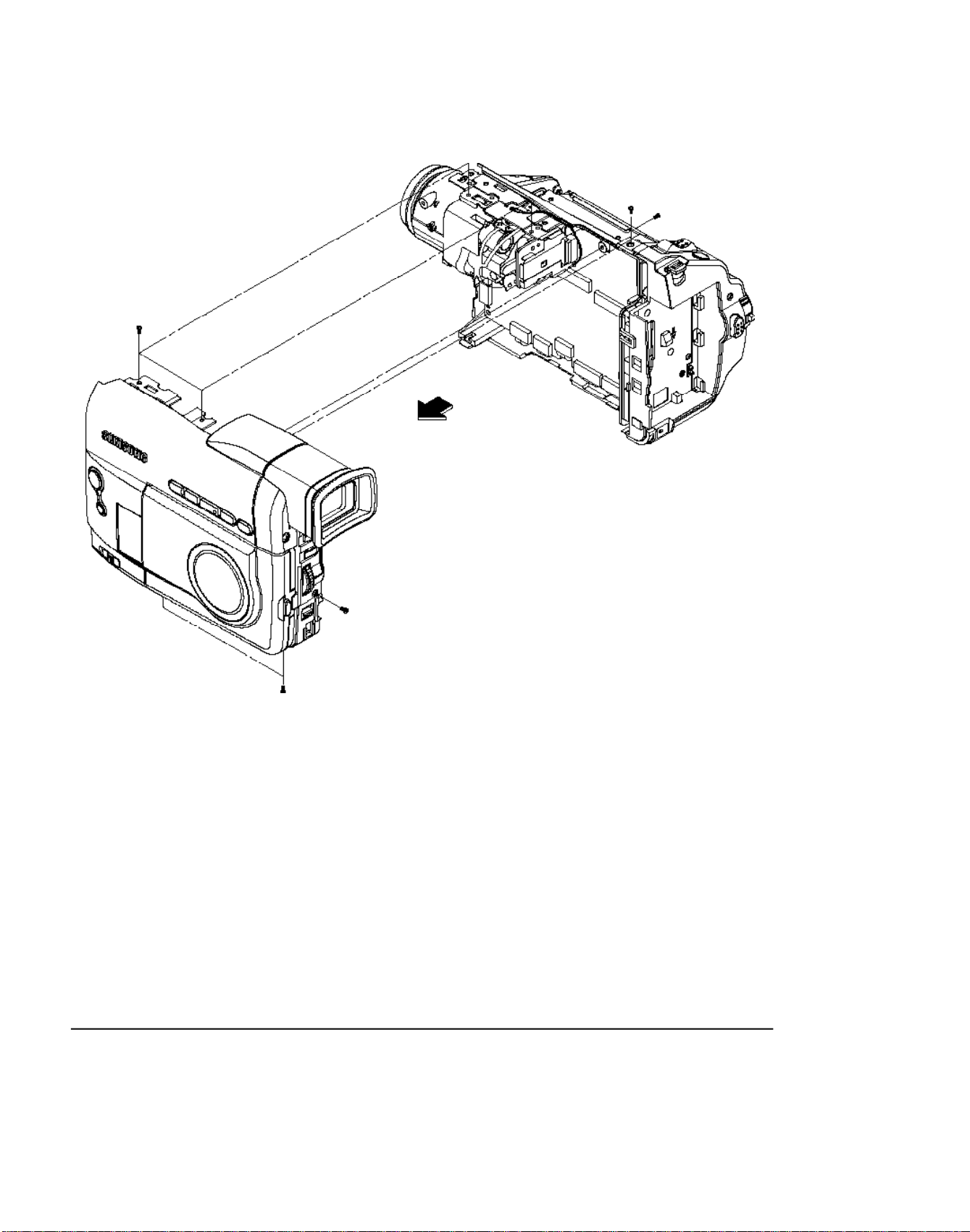
2-1-7 Ass’y Camera & Main PCB removal
(2) Remove ass’y camera & main
pcb in the direction of arrow
Disassembly and Reassembly
(1) Remove 3 screws
Fig. 2-7 Ass’y Camera & Main PCB removal
Samsung Electronics
2-7
Disassembly and Reassembly
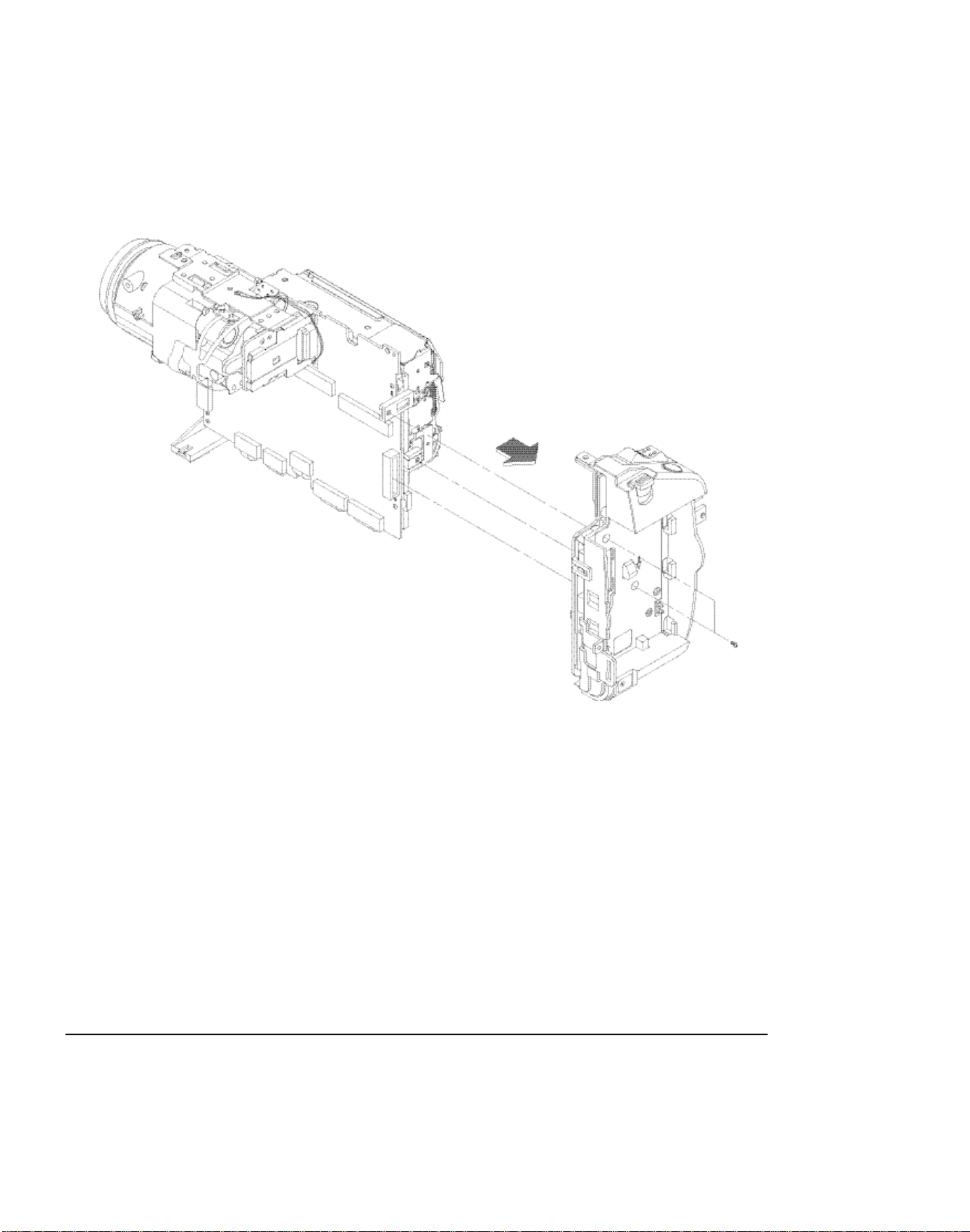
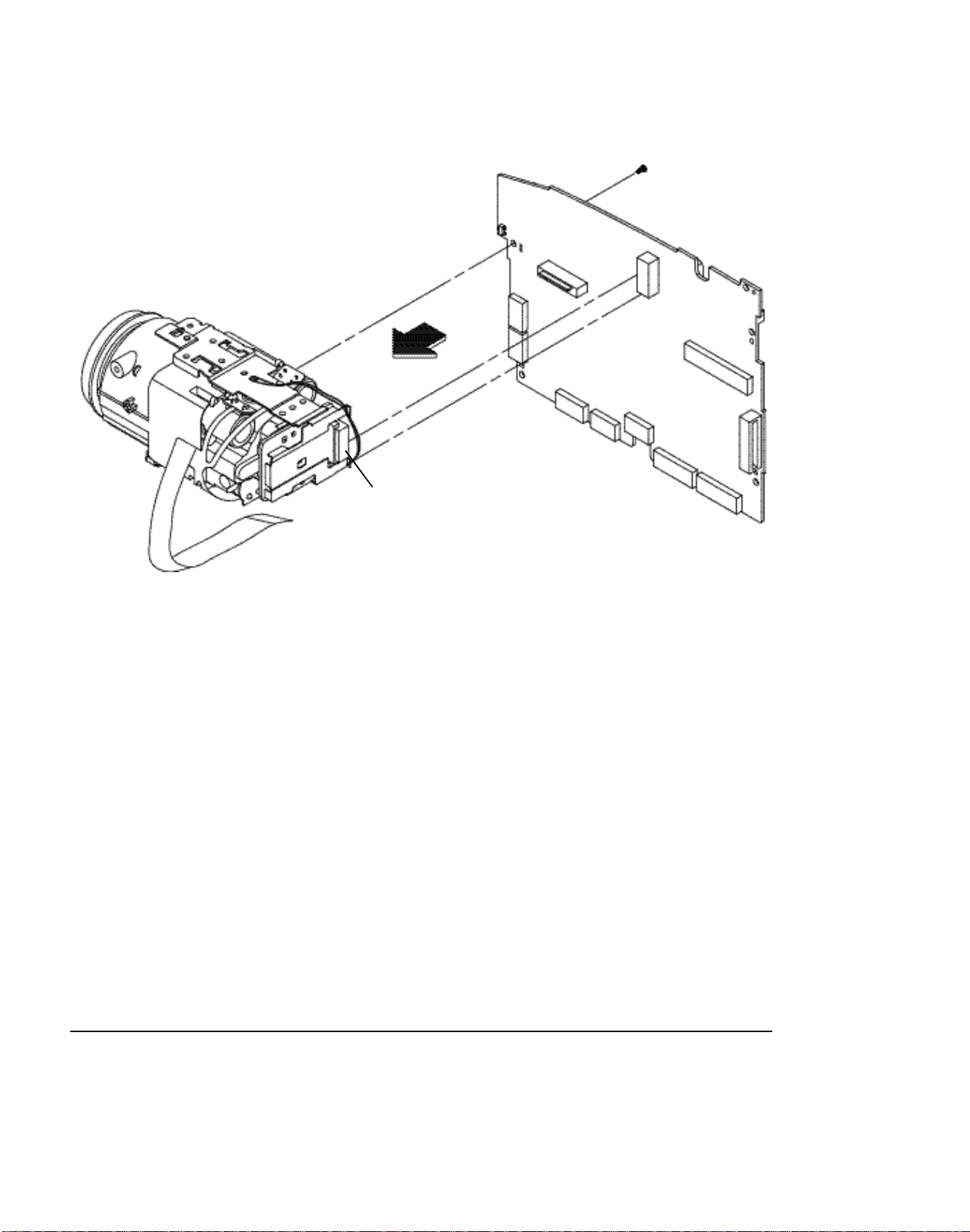
2-1-8 Ass’y-Camera removal
(3) Remove ass’y camera
in the direction of arrow
(2) Remove 1 screw
(1) Desolder
Fig. 2-8 Ass’y Camera removal
2-8
Samsung Electronics
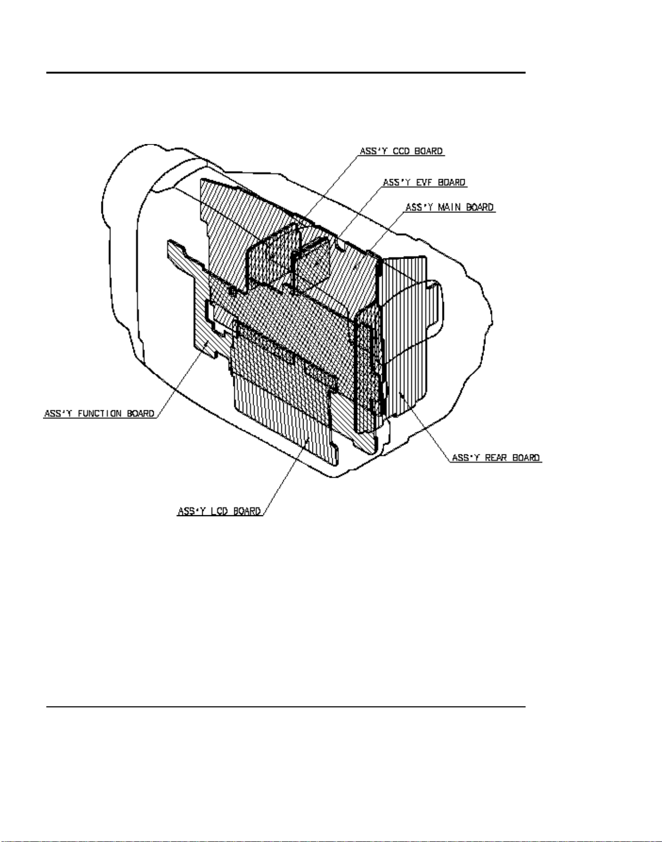
2-2 Circuit Boards Location
Disassembly and Reassembly
Samsung Electronics
Fig. 2-9 Circuit Boards Location
2-9
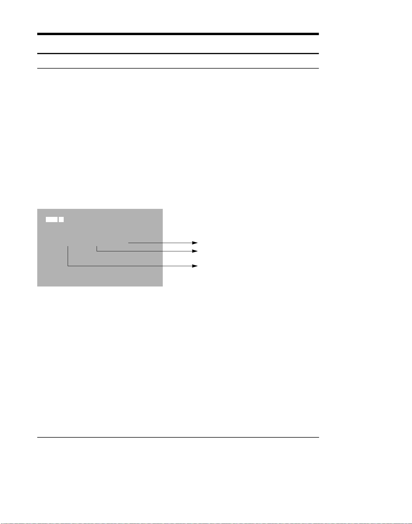
2-3 Connector Diagram
Disassembly and Reassembly
2-10
Fig. 2-10 Connector Diagram
Samsung Electronics
3. Alignment and Adjustment
3-1. VCR Adjustment
3-1-1. VCR Adjustment Preparation
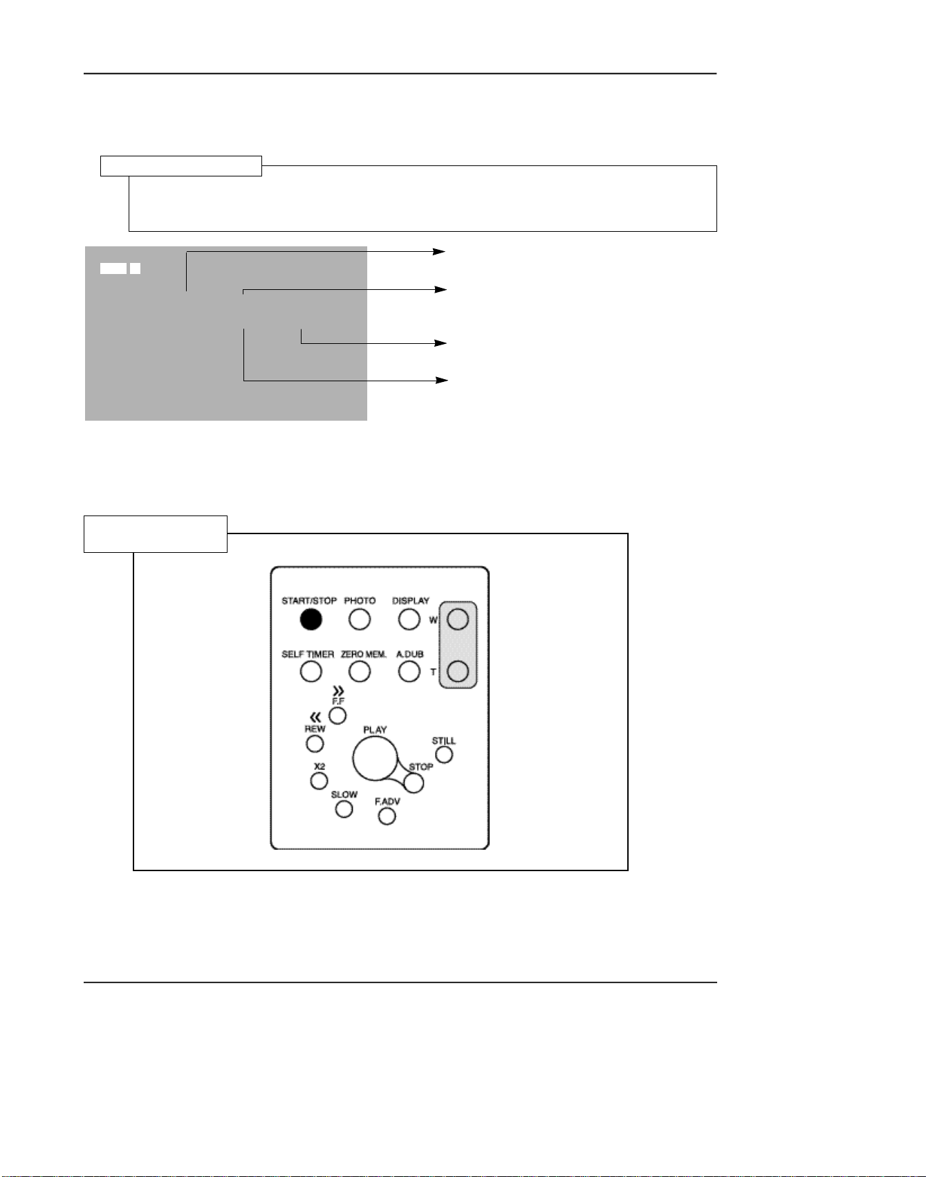
1. How to get into the VCR adjust mode.
STEP 1
1. Connect the power source.
2. Set the mode switch of the video camera to
"PLAYER" position.
3. Insert standard tape into the video camera and
set to "PLAY" position.
4.Press the "PLAY" button on the video camera or
the remote control
SP PLAY
0:00:00:01
NO MODE EVR EPR
1 V-REF 79H 79H
S64 LOO
01 01380
STEP 2
1. Press and hold the "F.ADV" button on the
remote control and "ENTER" button on the
video camera at the same time for more than 10
seconds.
2. When monitor OSD appears as shown below,
VCR adjustment mode has been activated successfully.
3. When changing the adjustment item after the
adjusted value is designated, press the
"START/STOP" button.
Indicates preset values
Indicates the adjusted values
Indicates current adjustment item.
Samsung Electronics 3-1
Adjustment and Adjustment
Fig.1. RIGHT CASE
Fig.2. REMOCON KEY
STEP 3 . If you want to finish the adjustment mode, you have to do Power Reset.
The Power Reset means that you pull out the power source and pull in it again.
Samsung Electronics3-2
Adjustment and Adjustment
3-1-2. VCR Adjustment
1. VCR Adjustment Items
Items DescriptionAdj. value
V-REF Adjustment Video reference
EXTRA 7D Audio VCO PLL
RECCUR 80 REC current
A-REF1 80 Audio 48KHz mode
A-REF2 80 Audio 44.1KHz mode
A-REF3 80 Audio 32KHz mode
HDSWP Adjustment Head Adjust switch
ZOOMVR Adjustment Adjust center value in the ZOOM switch
OPTION
DUBCUR 80
MODEL OPTION RESERVED(fixed value)
DUB REC CURRENT
* MODEL OPTION
Model Adj.value
VP-D73 C2
VP-D75i / SCD75 CE
SCD73 / VP-D73i C6
VP-D75 CA
VP-D76 / VP-D77 D2
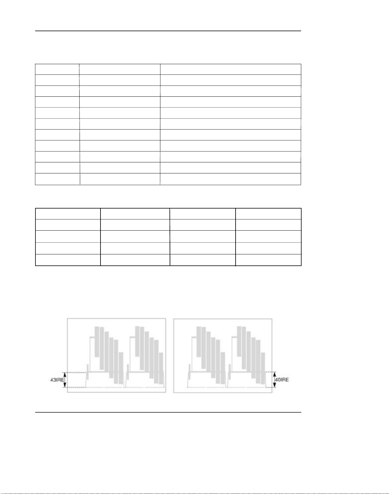
2. How to adjust Video-Reference (V-REF).
1) Connect video output cable to wave form scope. The wave form scope must be connected to monitor.
(75Ω termination)
2) Set to the VCR adjustment mode.
3) Adjust VREF so that SYNC level of video output signal is PAL(43 IRE) and NTSC(40 IRE).
Model Adj.value
VP-D76i D6
VP-D77i D6
SC-D77 D6
PAL NTSC
Samsung Electronics 3-3
Adjustment and Adjustment
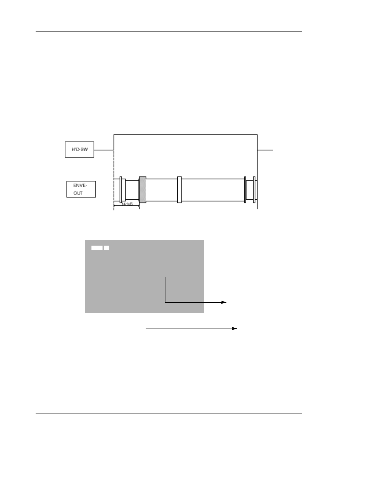
3. How to adjust Head Switching (HDSWP)
1) Connect No. 2 pin of WAFER CNR02 (HEAD-SW signal) for adjustment to CH1 of oscilloscope.
2) Connect No. 3 pin of WAFER CNR02 (ENVE-OUT signal) for adjustment to CH2 of oscilloscope.
3) Play standard tape.
4) Select HDSW of the video adjustment mode.
5) Adjust so that the time between HEAD-SW START and G1 START OF ENVE-OUT is 141µs (±10µs).
G1
4. Center Value Adjustment of Zoom Switch
SP PLAY
0:00:00:00
NO MODE EVR EPR
1
ZOOMVR
80H 80H
S64 LOO
(Preset value of the Zoom SW)
(Adjusted value of the
Zoom SW)
1) Select ZOOMVR in the video adjustment mode.
2) Adjust ZOOM SW so that the switch is put in the middle of T and W.
3) Adjust ZOOMVR so that the current value of ZOOM SW is equal to the adjusted ZOOMVR value.
Samsung Electronics3-4
3-1-3. PRML Adjustment Preparation
1. How to set up PRMLAdjustment Mode
PRML Adjustment Setup
1. Press the Display button in VCR adjustment mode.
2. When monitor OSD appears as shown below, PRML adjustment mode has been activated
successfully.
Adjustment and Adjustment
MODE REG PRML EPR
PLAY O OCO OCO
S64 LOO
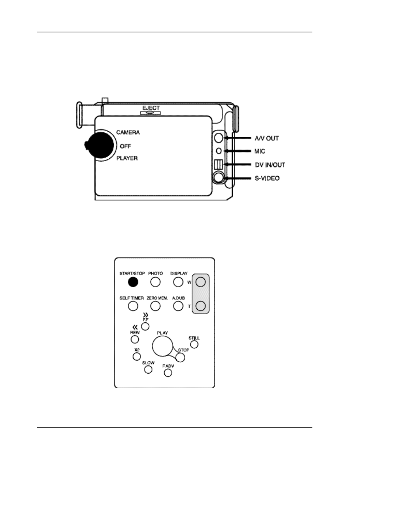
2. Remote Control Button Location
Remote Control
SP PLAY
Indicates address of adjusting item
by using from 00 to 24.
Indicates operating mode of PRML.
Indicates preset values.
Indicates the adjusted values.
3. Press the Address selection button(START/STOPbutton) to skip the next address in order to finish the
adjustment and store data. After finishing the adjustment, you have to do power reset.
The PRML BER will be set to the right adjustment when shipping out video camera and PCB ASSY from
*
factory.
Samsung Electronics 3-5

Adjustment and Adjustment
3-1-4. PRML Adjustment
1. How to set up PRMLAdjustment Mode
Address Name
00
01
02
03
04
05
06
07
08
09
0A
0B
0C
0D
0E
0F
24
PGC/SQPI/FIRO
IDO/DOD/ATFAQ/FIR4
GDH0/FIR1H0
GDH1/FIR1H1
L P G C / D AT F / P G C E N / T D O I / F I R 3 H 0
BPGC/FCLP/FIR3H1
LTG/LPGC/BPLG/TC13/TC2/FIR2
AT F F C / D O H G / AT F H G / H G S E L / S L E E P
D D O S C / S E F T H / D L Z I / TA D A P T / V I T
ATFSEL/SYMC/DAMP
EZCNT/LPFBYP/PDTST/...
HLD/FCHO/BSTH0
CMXEN/FCH1/BSTH1
ATGH0/DOGCH0/TP1SEL
ATGCH1/DOGCH1/TSEL
FRQ/RLZSEL/...
AE/DZ/INTL/.../TWR
PB
0C0
0 0 0
3 0 0
3 0 0
4 0 0
6 0 0
8 0 5
#0 0
2 1 E
2 2 3
0 0 4
2 2 A
22A
F 6 5
8 6 0
0 0 F
FA 2
SP
SEARCH/SLOW
0C0
0 0 0
3 0 0
3 0 0
4 0 0
6 0 0
8 0 5
#0 0
A 1 E
2 2 3
0 0 4
2 8 A
2 8 A
8 6 5
8 6 0
0 0 F
7 A 2
MODE
PB
0C0
0 0 0
7 C 0
7 C 0
4 0 0
5 0 0
8 0 5
#0 0
228
2 2 3
2 C A
2 C A
865
F 6 5
8 6 0
0 0 F
FA F
LP
SEARCH
0C0
0 0 0
7C0
7C0
4 0 0
5 0 0
8 0 5
# C 0
A 2 8
2 2 3
2 0 0
2 8 A
2 8 A
F 5 5
8 5 0
0 0 F
7 A F
VP
SLOW
0C0
0 0 0
7C0
7C0
400
500
805
# 8 0
A28
223
200
28A
28A
F55
850
00F
7AF
2. BER Adjustment Specifications (Reference)
1) Get into the VCR adjustment mode.
;Press and hold the “F.ADV” button on the remote control and “ENTER” button on the video camera
at the same time for more than 10 seconds.
2) Turn offAdaptive. ............................................................................7A2 ;REG24
3) Find out the optional minimum BER value in REG. 12 BOOST.
start values ........................................................................................28A ;REG12
The optimum means the number error is less than 10 EA. ;Current D73/D75/D76/
D77 manufacturing standard
If the minimum value is as the followings, designate as the right values.
Min ........................................................................................................... ;Selection valueless
iess than 18 .......................................................................................18 ;REG12===24A
19 ........................................................................................................19 ;REG12===26A
20 ........................................................................................................20 ;REG12===28A
Samsung Electronics3-6

Adjustment and Adjustment
4) Find out the optimally minimum BER value in REG. 11 BOOST.
start values . . . . . . . . . . . . . . . . . . . . . . . . . . . . . . . . . . . . . . . . . . . . .28A ;REG11
The optimum means the number of error is less than 10 EA. ;Current D73/D75/D76/
D77 manufacturing
standard
If the minimum value is as the followings, designate as the right values.
[Add +2 to select the one.]
Min . . . . . . . . . . . . . . . . . . . . . . . . . . . . . . . . . . . . . . . . . . . . . . . . . . ;Selection valueless
less than18 . . . . . . . . . . . . . . . . . . . . . . . . . . . . . . . . . . . . . . . . .18 ;REG11 ===24A
19 . . . . . . . . . . . . . . . . . . . . . . . . . . . . . . . . . . . . . . . . . . . . . . . . .19 ;REG11 ===26A
20 . . . . . . . . . . . . . . . . . . . . . . . . . . . . . . . . . . . . . . . . . . . . . . . . .20 ;REG11 ===28A
21 . . . . . . . . . . . . . . . . . . . . . . . . . . . . . . . . . . . . . . . . . . . . . . . . .21 ;REG11 ===2AA
5) Turn on Adaptive. . . . . . . . . . . . . . . . . . . . . . . . . . . . . . . . . . . . . . . . . . ;REG24 ===FA2
6) Check the value is input to unit correctly.
Samsung Electronics 3-7

Adjustment and Adjustment
3-2 Camera Adjustment
Note: How to adjust the camera system.
1) EEPROM stores confirmed adjustment value of each adjustment step.
2) DSP (Digital Signal Process : ICP04-MAIN BOARD) digitalizes the camera signal.
3) When changing IC404-MAIN BOARD of EEPROM, readjust main board. While changing LCD
board- and EVF board- always readjust each part.
Since EEPROM stores confirmed adjustment value of each adjustment step, readjusting must be
performed in order to store the changed data.
4) Adjust the following items after changing LENS ASSY.
a. LENS ZOOM TRACK
b. AUTO HALL
c. AUTO IRIS
5) Adjust the following items after changing EEPROM and MAIN BOARD.
a. LENS ZOOM TRACK
b. AUTO HALL
c. AE TARGET
d. AUTO GAIN CONTROL
e. AUTO IRIS
f. AUTO WHITE BALANCE (indoor)
g. AUTO WHITE BALANCE (outdoor)
3-2-1 Adjustment Preparation
1. Measuring Instrument
1) DC power supply
2) Oscilloscope
3) PALvectorscope, NTSC Vectorscope
4) PALwave form monitor, NTSC wave fonitor
5) PALTV or monitor, NTSC TV or monitor
6) Color bar chart
Gray scale chart
2) Camera Pcb configuration
1) Main PCB
2) CCD PCB
3) EVF PCB
4) LCD PCB
3. Before you start
1) Use the buttons on the remote control when adjusting camera.
2) Press the "START/STOP" button when storing confirmed adjustment value of each adjustment step in
EEPROM.
3) There is a flicker on screen after finishing each adjustment step.
4) To clear the adjustment mode, pull out the power source.
Samsung Electronics3-8
4. Functions of each button on the Remote Control
Adjustment and Adjustment
Button
START/STOP (Confirm)
STOP (Data Down)
PLAY (Data Up)
FF (Mode Up)
REW (Mode Down)
SELF TIMER
In adjustment mode, the buttons of the remote control is as the followings.
Stores changed value in the adjustment and auto adjustment mode.
Changes data in the adjustment state.
Changes mode.
Pre-confirm
Description
Note: In service adjustment mode, button names are different from those in customer function control
mode.
e.g.) "START/STOP" is the same as "Confirm".
5. How to set up the camera adjustment mode
STEP 1
1) Connect the power source
(battery/DC cable).
2) Open Housing from video
camera.
STEP 2
Press and hold the "EDIT(+)" button
and "ENTER" button on the video
camera at the same time for more
than 5 seconds.
3) Set the "POWER(CAMERA/PLAYER)" switch to "CAMERA" position.
STEP 3
4) The OSD appears.
Monitor OSD shows "16D XX XX".
Then camera adjustment mode has
Note : "XX" indicates variable values.
Samsung Electronics 3-9
been activated successfully.

Adjustment and Adjustmentnt
Addr. NTSC PAL NAME
0 0 0 H1_INV
1 0 0 HCNT_SET
2 AA 55 H1_DLY
3 23 1 SHP_DLY
4 7A 2A ADCLK_DLY
5 33 33 SHP_WITH
6 A7 A6 V_SKIP
7 0 0 FLD_INV
8 0 0 Hi_SHUT_VAL
9 0 0 Lo_SHUT_VAL
A 8B 8A FCM_Addr_Lo
B 0 0 FCM_Addr_Hi
C 1 0 ITUR601
D 10 10 RG_SEL
E 0 0 DAC0_PIN51
F 0 0 DAC1_PIN52
10 FF FF H_ZM_RATIO
11 4 2 H_ZM_START
12 0 0 H_ZM_SUB
13 0 0 V_ZM_RATIO
14 1 1 V_ZM_SUB_Odd
15 30 37 V_ZM_SKIP
16 0 0 YC_DLY
17 E0 E0 Linear/Spline
18 1 21 UVCLK_INV
19 B5 B5 H_Mirr_Addr
1A 68 68 F_Mirr_Addr
1B C0 0 H_MOSAIC
1C C0 C0 V_MOSAIC
1D 38 38 HSIZE_AUTO_ZM
1E 38 38 VSIZE_AUTO_ZM
1F 0 0 H1_INV
20 10 13 ADCLK_DLY
21 FB FB P_OFFSET
22 10 10 P_THR
23 0 0 P_RAM_Hi
24 0 0 P_RAM_Mdl
25 0 0 P_RAM_Lo
26 20 20 P_FIND_CNT
27 10 E P_WH_START
28 E8 E4 P_WH_END
29 8 8 P_WV_START
2A 77 8E P_WV_END
2B 0 0 P_TEST
2C 0 0 PATTERN_GEN
2D 0 0
2E 0 0
2F 0 0
30 A8 AD YV_APT_BKTH
Samsung Electronics3-10

Addr. NTSC PAL NAME
31 E E YH_APT_GN_POSI
32 CE CE YV_APT_GN_POSI
33 4 2 YAPT_NSlice
34 D8 D8 Y_Hi_REF
35 78 78 EDGE_REF
36 E0 E0 YV_APT_LPF_SEL
37 6 6 YAPT_NS_AftGMA
38 F8 F8 YWC
39 7C 7C Y_APT_Clip
3A 62 62 YD_ENH_TH/GAIN
3B B1 A9 YV_APT_GN_NEGA
3C 59 69 YH_APT_GN_NEGA
3D 8F 8F HiFALL/EGFALL
3E 0 0
3F 0 0
40 98 98 Y_GAIN
41 90 90 DSE_Y_GAIN
42 8A 8C C_GAIN
43 0 0 YART
44 C0 C0 YH_PST/EMBO_GN
45 52 52 PSTL_OFFET
46 35 35 EMBO_OFFSET
47 60 60 GRP_DLY
48 0 0
49 0 0
4A 0 0
4B 0 0
4C 0 0
4D 0 0
4E 0 0
4F 0 0
50 A8 A8 DYV_APT_BKTH
51 C C DYHAPT_GN_POSI
52 50 50 DYHAPT_GN_NEGA
53 C C DYVAPT_GN_POSI
54 B0 A0 DYVAPT_GN_NEGA
55 10 10 DY_APT_NSlice
56 70 70 DY_APT_Clip
57 0 0 DYHiLight_GN
58 6 6 DYAPT_NS_GAM
59 62 62 DYDet_EN_TH/GN
5A 10 10 DYVAPT_LPF_SEL
5B 36 36 DWH_START
5C A5 A5 DWH_END
5D 2D 2D DWV_START
5E 7F 7F DWV_END
5F 0 0
60 6 6 S1/S2_SEL
61 46 46 CR_COEF
Adjustment and Adjustment
Samsung Electronics 3-11

Adjustment and Adjustment
Addr. NTSC PAL NAME
62 66 66 CB_COEF
63 D C CRDS
64 FC FE CBDS
65 0 0 CGDS
66 0 0 CRCB_WB_Hi
67 33 32 CRWB
68 9D A6 CBWB
69 24 24 CGWB
6A 59 59 CRRG
6B D9 D9 CBRG
6C F2 F2 CRBG
6D 72 72 CBBG
6E 0 0
6F 0 0
70 90 9C C_RY_GP
71 90 90 C_RY_GN
72 12 12 C_RY_HP
73 12 12 C_RY_HN
74 5E 60 C_BY_GP
75 58 5D C_BY_GN
76 17 17 C_BY_HP
77 A A C_BY_HN
78 8 0 C_KEY_Slope1
79 10 0 C_KEY_Slope2
7A 0 0 CKEY_Slpe12_Hi
7B 0 0 C_HUE_FIX
7C 0 0
7D 0 0
7E 0 0
7F 0 0
80 2 2 Y_GAMMA1
81 7 7 Y_GAMMA2
82 12 12 Y_GAMMA3
83 28 28 Y_GAMMA4
84 44 44 Y_GAMMA5
85 68 68 Y_GAMMA6
86 9A 9A Y_GAMMA7
87 EA EA Y_GAMMA8
88 2 2 C_GAMMA1
89 7 7 C_GAMMA2
8A 12 12 C_GAMMA3
8B 28 28 C_GAMMA4
8C 44 44 C_GAMMA5
8D 68 68 C_GAMMA6
8E 9A 9A C_GAMMA7
8F EA EA C_GAMMA8
90 5C 5C AF_W1H_STRT
91 A0 A0 AF_W1H_END
92 27 35 AF_W1V_STRT
3-12 Samsung Electronics

Addr. NTSC PAL NAME
93 5F 79 AF_W1V_END
94 14 13 AF_W2H_STRT
95 E4 E3 AF_W2H_END
96 8 9 AF_W2V_STRT
97 76 8E AF_W2V_END
98 14 13 AE_W1H_STRT
99 E4 E3 AE_W1H_END
9A 8 9 AE_W1V_STRT
9B 76 8E AE_W1V_END
9C 48 47 AE_W2H_STRT
9D B0 AF AE_W2H_END
9E 23 2A AE_W2V_STRT
9F 5A 6C AE_W2V_END
A0 17 16 AWB_H_STRT
A1 E7 E6 AWB_H_END
A2 8 9 AWB_V_STRT
A3 76 8E AWB_V_END
A4 FF FF AE_THR_HiGH
A5 0 0 AE_THR_LOW
A6 B0 B0 AWB_THR_HiGH
A7 40 40 AWB_THR_LOW
A8 B0 B0 AF_Clip_THR
A9 F0 F0 AE_Clip_THR
AA 4 4 OZONE_SEL
AB 0 0
AC 0 0
AD 0 0
AE 0 0
AF 0 0
B0 0 0 DIS-DIS ON
B1 98 98 DIS-FRAME
B2 A0 E0 DIS-DVC
B3 0 0 DIS-KX
B4 0 0 DIS-KY
B5 B2 B2 DIS_SP_H
B6 16 1A DIS_SP_V
B7 C0 C0 DIS_WIDTHL
B8 3 3 DIS_WIDTHH
B9 F2 1F DIS_HEIGHTL
BA 0 1 DIS_HEIGHTH
BB E2 E2 DIS_PIP_HSPL
BC 2 2 DIS_PIP_HSPH
BD 90 A6 DIS_PIP_VSPL
BE 0 0 DIS_PIP_VSPH
BF B6 DE DIS_PBOX_HSPL
C0 2 2 DIS_PBOX_HSPH
C1 AE CF DIS_PBOX_VSPL
C2 0 0 DIS_PBOX_VSPH
C3 20 20 DIS_PIP_DSP_HADJ
C4 2 2 DIS_PIP_DSP_VADJ
Adjustment and Adjustment
Samsung Electronics
3-13

Adjustment and Adjustment
Addr. NTSC PAL NAME
C5 20 22 DIS_PBOX_DSP_HADJ
C6 1 2 DIS_PBOX_DSP_VADJ
C7 9B 9B DIS_OUT_OFF
C8 9B 9B DIS_OUT_OFF1
C9 B5 B5 DIS_GR_MODE
CA A C DIS_CLK2_SEL
CB A0 C0 DIS_SIS2_SEL0
CC 25 24 DIS_OSD_SEL
CD 0 0 DIS_PIP_SIS2_SEL
CE 1E 1E DIS_DCLP_R
CF 24 24 DIS_DCLP_F
D0 4 4 DIS_YHAFS
D1 C0 80 DIS_APCLP
D2 8 6 DIS_APSC
D3 0 0 DIS_ECST
D4 0 0 DIS_ECSG
D5 83 83 DIS_G1
D6 8F 8D DIS_G0
D7 0 0 DIS_HUE1_OFF
D8 0 0 DIS_ECHUE1
D9 0 0 DIS_ECHUE2
DA 10 10 DIS_APSCV
DB F0 F0 DIS_WV1
DC 90 90 DIS_WH1
DD 4 4 DIS_OVERLAY
DE 0 0 DIS_T0
DF 10 10 DIS_MAN_T0
E0 2 2 DIS_TIIR_TH
E1 0 0 DIS_LINEAR
E2 0 0 DIS_GA0
E3 8 8 DIS_GA1
E4 10 10 DIS_GA2
E5 18 18 DIS_GA3
E6 20 20 DIS-GA4
E7 30 30 DIS_GA5
E8 40 40 DIS_GA6
E9 60 60 DIS_GA7
EA 7F 7F DIS_GA8
EB 0 0 DIS_GB0
EC 8 8 DIS_GB1
ED 10 10 DIS_GB2
EE 18 18 DIS_GB3
EF 20 20 DIS_GB4
F0 30 30 DIS_GB5
F1 40 40 DIS_GB6
F2 60 60 DIS_GB7
F3 7F 7F DIS_GB8
F4 60 60 DIS_SP_HM
F5 16 1A DIS_SP_VM
F6 DC 7 DIS_HEIGHTML
3-14
Samsung Electronics

Addr. NTSC PAL NAME
F7 0 1 DIS_HEIGHTMH
F8 0 0 DIS_WIDTHML
F9 3 3 DIS_WIDTHMH
FA FB FB DIS_KXMD
FB FB FB DIS_KYMD
FC F7 F7 DIS_OSD_MODE
FD C1 C1 DIS_DIS_ENX
FE 0 0 DIS_OXL
FF 0 0 DIS_OXH
100 0 0 DIS_OY
101 0 0 DIS_CX
102 0 0 DIS_CY
103 41 22 DIS_AX/AY
104 33 33 DIS_AUTO_CENT
105 88 88 DIS_VGGAINX
106 21 21 DIS_VGSTEP
107 48 48 DIS_THR_SEL
108 11 11 DIS_CXY_BIAS
109 A5 A5 DIS_MATCHX_EN
10A A5 A5 DIS_MATCHY_EN
10B 68 68 DIS_SHMFBC
10C E0 E0 DIS_MVIIR_EN
10D 24 24 DIS_OZNSEL
10E 73 89 DIS_OAEVE_WB
10F 1D 21 DIS_OAEVS_WB
110 D4 D6 DIS_OAEHE_WB
111 26 2A DIS_OAEHS_WB
112 61 70 DIS_OAEVE_WA
113 1C 25 DIS_OAEVS_WA
114 B1 B3 DIS_OAEHE_WA
115 4B 4F DIS_OAEHS_WA
116 5F 79 DIS_OAFVE_W2
117 27 35 DIS_OAFVS_W2
118 A0 A0 DIS_OAFHE_W2
119 5C 5C DIS_OAFHS_W2
11A 74 8A DIS_OAFVE_W1
11B 5 3 DIS_OAFVS_W1
11C C8 C8 DIS_OAFHE_W1
11D 2C 2C DIS_OAFHS_W1
11E 0 0 DIS_OYL_TH
11F FF FF DIS_OYH_TH
120 A8 80 DIS_OAECLIP_TH
121 B0 E8 DIS_OAFCLIP_TH
122 0 0 DIS_PFCNT_M1
123 10 10 DIS_PTHRESH
124 0 0 DIS_POFFSET
125 3 3 DIS_PCMD
126 0 0 DIS_PRAMIL
127 0 0 DIS_PRAMIM
128 0 0 DIS_PRAMIH
Adjustment and Adjustment
Samsung Electronics
3-15
 Loading...