

samsung VP-D451(I), VP-D453(I), VP-D454(I), VP-D455(I), VP-D452BI Service Manual
...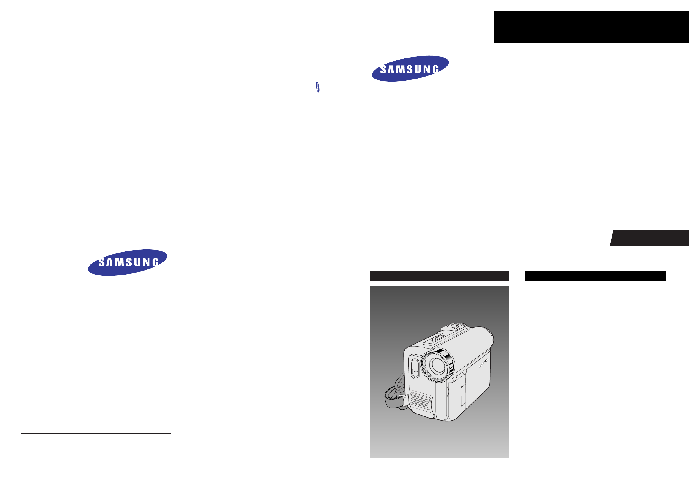
DIGITAL VIDEO CAMCORDER
Chassis : Tiger
BASIC : VP-D455
Application Models
: VP-D451(I)/VP-D453(I)/
VP-D454(I)/VP-D455(I)/
VP-D452BI/VP-D6650I
VP-D6640I/VP-D6620I
Application Area
:
XEF, XEU, XEG, XET, XEV, XEC, XSA, CDM,
XST, XEO, XEH, XEP, XEE, EAP, EUR, XEN,
HACO, TAW, TIT, COL, SEO, XSS, SED, XSH,
XSG, FES, XTL, CHN, ZAM, STS, SMR, XFA,
ITN, KNT, XSE, FPT, RAD, AND, UMG, AFR
SERVICE
Ultra Compact Design DVC
Use Built-in Flash Memory
(VP-D454(i)/D455(i)/D6650I Only)
Multi Memory Card Slot
(VP-D454(i)/D455(i)/D6650I Only)
Direct Print System : PictBridge ™
USB 2.0
High quality MPEG4
Digital Image Stabilizer
Real Wide mode (16:9)
Manual
DIGITAL VIDEO CAMCORDER Merit & Character regarding Product
SERVICE MANUAL
VP-D451(I)/D452BI/D453(I)/D454(I)/D455(I)/D6620I/D6640I/D6650I
ELECTRONICS
© Samsung Electronics Co., Ltd. FEB. 2005
Printed in Korea
AD82-00104A
This Service Manual is a property of Samsung Electronics Co .,Ltd.
Any unauthorized use of Manual can be punished under applicable
International and/or domestic law.

CONTENTS
1. Precautions (1-1 ~ 1-2)
2. Product Specification (2-1 ~ 2-4)
2-1 Product Specification (2-1)
2-2 Chassis Product Specification (2-2)
2-3 Accessories Supplied with Camcorder (2-3)
3. Alignment and Adjustments (3-1 ~ 3-20)
3-1 VCR Adjustment (3-1)
3-2 Camera Adjustment (3-3)
3-3 LCD Adjustment (3-7)
3-4 Deck Adjustment (3-11)
4. Disassembly and Reassembly (4-1 ~ 4-16)
4-1 Cabinet and PCB (4-1)
4-2 Deck (4-5)
5. Exploded View and Parts List (5-1 ~ 5-20)
5-1 Ass’y Chassis (5-2)
5-2 Ass’y Left (5-4)
5-3 Ass’y LCD (5-6)
5-4 Ass’y Right (5-8)
5-5 Ass’y Rear (5-10)
5-6 Ass’y CVF (5-12)
5-7 Ass’y Case Left (5-13)
5-8 Ass’y Front (5-14)
5-9 Ass’y Housing (5-15)
5-10 Mechanical Parts (Main Chassis) (5-16)
5-11 Mechanical Parts (Sub Chassis) (5-18)
6. Electrical Parts List (6-1 ~ 6-14)
7. Block Diagram (7-1 ~ 7-4)
7-1 All Block Diagram (7-1)
7-2 IC102 Block Diagram (7-2)
7-3 IC201 Block Diagram (7-3)
8. Wiring Diagram (8-1 ~ 8-2)

9. PCB Diagrams (9-1 ~ 9-10)
9-1 Main PCB (9-2)
9-2 Front PCB (9-6)
9-3 Function PCB (9-6)
9-4 CVF PCB (9-7)
9-5 CCD PCB (9-7)
9-6 Jack PCB (9-8)
9-7 LCD PCB (9-8)
9-8 Rear PCB (9-9)
10. Schematic Diagrams (10-1 ~ 10-20)
10-1 DC/DC Converter (Main PCB) (10-2)
10-2 Servo (Main PCB) (10-3)
10-3 System Control (Main PCB) (10-4)
10-4 Pre Amp/PRML (Main PCB) (10-5)
10-5 DV-1Chip (Main PCB) (10-6)
10-6 Video-Interface (Main PCB) (10-7)
10-7 Audio (Main PCB) (10-8)
10-8 Camera Process (Main PCB) (10-9)
10-9 DSP (Main PCB) (10-10)
10-10 Camera Memory 1 (Main PCB) (10-11)
10-11 Camera Memory 2 (Main PCB) (10-12)
10-12 CCD (CCD PCB) (10-13)
10-13 Front (Front PCB) (10-14)
10-14 Jack (Jack PCB) (10-15)
10-15 Rear (Rear PCB) (10-16)
10-16 Function (Function PCB) (10-17)
10-17 CVF (CVF PCB) (10-18)
10-18 LCD (LCD PCB) (10-19)
11. Operating Instructions and Installation (11-1 ~ 11-6)
12. Trouble Shooting (12-1 ~ 12-8)
CONTENTS

13. Circuit Operating Descriptions (13-1 ~ 13-12)
13-1 Digital Camcoder Summary (13-1)
13-2 Set Explanation (13-2)
13-3 H/W Function Specifications (13-6)
14. Reference Information (14-1 ~ 14-44)
14-1 Deck Operating Description (14-1)
14-2 PC INTERFACE (14-30)
14-3 Memory Card (14-34)
14-4 Camcorder Function Description (14-39)
CONTENTS
Samsung Electronics 1-1
1. Precautions
1. Be sure that all of the built-in protective devices are
replaced. Restore any missing protective shields.
2. When reinstalling the chassis and its assemblies, be
sure to restore all protective devices, including :
control knobs and compartment covers.
3. Make sure that there are no cabinet openings
through which people--particularly children
--might insert fingers and contact dangerous
voltages. Such openings include the spacing
between the picture tube and the cabinet mask,
excessively wide cabinet ventilation slots, and
improperly fitted back covers.
If the measured resistance is less than 1.0 megohm
or greater than 5.2 megohms, an abnormality exists
that must be corrected before the unit is returned
to the customer.
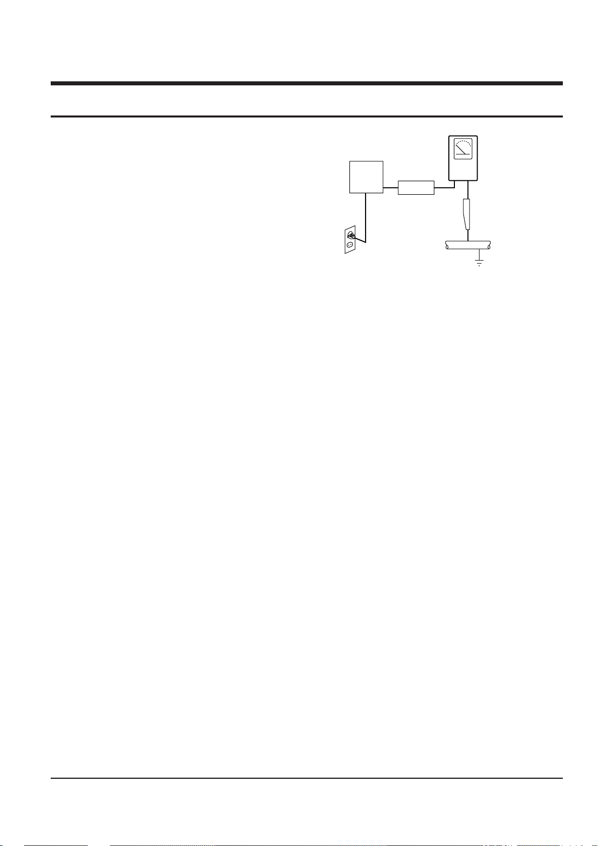
4. Leakage Current Hot Check (See Fig. 1-1) :
Warning : Do not use an isolation transformer
during this test. Use a leakage current tester or a
metering system that complies with American
National Standards Institute (ANSI C101.1,
Leakage Current for Appliances), and Underwriters
Laboratories (UL Publication UL1410, 59.7).
5. With the unit completely reassembled, plug the AC
line cord directly the power outlet. With the unit’s
AC switch first in the ON position and then OFF,
measure the current between a known earth
ground (metal water pipe, conduit, etc.) and all
exposed metal parts, including : antennas, handle
brackets, metal cabinets, screwheads and control
shafts. The current measured should not exceed
0.5 milliamp. Reverse the power-plug prongs in the
AC outlet and repeat the test.
6. X-ray Limits :
The picture tube is designed to prohibit X-ray
emissions. To ensure continued X-ray protection,
replace the picture tube only with one that is the
same type as the original.
Fig. 1-1 AC Leakage Test
7. Antenna Cold Check :
With the unit’s AC plug disconnected from the
AC source, connect an electrical jumper across the
two AC prongs. Connect one lead of the ohmmeter
to an AC prong.
Connect the other lead to the coaxial connector.
8. High Voltage Limit :
High voltage must be measured each time
servicing is done on the B+, horizontal deflection
or high voltage circuits.
Heed the high voltage limits. These include the
X-ray protection Specifications Label, and the
Product Safety and X-ray Warning Note on the
service data schematic.
9. Some semiconductor (“solid state”) devices are
easily damaged by static electricity.
Such components are called Electrostatically
Sensitive Devices (ESDs); examples include
integrated circuits and some field-effect transistors.
The following techniques will reduce the
occurrence of component damage caused by static
electricity.
10. Immediately before handling any semiconductor
components or assemblies, drain the electrostatic
charge from your body by touching a known
earth ground. Alternatively, wear a discharging
Wrist-strap device. (Be sure to remove it prior to
applying power--this is an electric shock
precaution.)
DEVICE
UNDER
TEST
(READING SHOULD
NOT BE ABOVE
0.5mA)
LEAKAGE
CURRENT
TESTER
EARTH
GROUND
TEST ALL
EXPOSED METER
SURFACES
ALSO TEST WITH
PLUG REVERSED
(USING AC ADAPTER
PLUG AS REQUIRED)
2-WIRE CORD

Precautions
1-2 Samsung Electronics
11. High voltage is maintained within specified limits
by close-tolerance, safety-related components and
adjustments. If the high voltage exceeds the
specified limits, check each of the special
components.
12. Design Alteration Warning :
Never alter or add to the mechanical or electrical
design of this unit. Example : Do not add
auxiliary audio or video connectors.
Such alterations might create a safety hazard.
Also, any design changes or additions will void
the manufacturer’s warranty.
13. Hot Chassis Warning :
Some TV receiver chassis are electrically
connected directly to one conductor of the AC
power cord. If an isolation transformer is not
used, these units may be safely serviced only if
the AC power plug is inserted so that the chassis
is connected to the ground side of the AC source.
To confirm that the AC power plug is inserted
correctly, do the following : Using an AC
voltmeter, measure the voltage between the
chassis and a known earth ground. If the reading
is greater than 1.0V, remove the AC power plug,
reverse its polarity and reinsert. Re-measure the
voltage between the chassis and ground.
14. Some TV chassis are designed to operate with 85
volts AC between chassis and ground, regardless
of the AC plug polarity. These units can be safely
serviced only if an isolation transformer inserted
between the receiver and the power source.
15. Never defeat any of the B+ voltage interlocks.
Do not apply AC power to the unit (or any of its
assemblies) unless all solid-state heat sinks are
correctly installed.
16. Always connect a test instrument’s ground lead to
the instrument chassis ground before connecting
the positive lead; always remove the instrument’s
ground lead last.
17. Observe the original lead dress, especially near
the following areas : Antenna wiring, sharp
edges, and especially the AC and high voltage
power supplies. Always inspect for pinched, outof-place, or frayed wiring. Do not change the
spacing between components and the printed
circuit board. Check the AC power cord for
damage. Make sure that leads and components
do not touch thermally hot parts.
18. Picture Tube Implosion Warning :
The picture tube in this receiver employs
“integral implosion” protection. To ensure
continued implosion protection, make sure that
the replacement picture tube is the same as the
original.
19. Do not remove, install or handle the picture tube
without first putting on shatterproof goggles
equipped with side shields. Never handle the
picture tube by its neck. Some “in-line” picture
tubes are equipped with a permanently attached
deflection yoke; do not try to remove such
“permanently attached” yokes from the picture
tube.
20. Product Safety Notice :
Some electrical and mechanical parts have special
safety-related characteristics which might not be
obvious from visual inspection. These safety
features and the protection they give might be
lost if the replacement component differs from the
original--even if the replacement is rated for
higher voltage, wattage, etc.
Components that are critical for safety are
indicated in the circuit diagram by shading,
( or ).
Use replacement components that have the same
ratings, especially for flame resistance and
dielectric strength specifications. Areplacement
part that does not have the same safety
characteristics as the original might create shock,
fire or other hazards.

Samsung Electronics
2-1
2. Product Specifications
2-1 Product Specification
Video signal
Video recording system
Audio recording system
Usable cassette
Tape speed
Tape recording time
FF/REW time
Image device
Lens
Filter diameter
Size/dot number
LCD monitor Method
Viewfinder
Video output
S-video output
Audio output
DV input/output
USB output
External mic
Power source
Power source type
Power consumption
(Recording)
Operating temperature
Storage temperature
External dimension
Weight
Internal MIC
Remote control
(VP-D453(i)/D454(i)/
D455(i) only)
System
LCD monitor/Viewfinder
Connectors
General
PAL
2 rotary heads, Helical scanning system
Rotary heads, PCM system
Digital video tape (6.35mm width): Mini DV cassette
SP: approx. 18.83mm/s LP: approx. 12.57mm/s
SP: 60 minutes (when using DVM 60), LP: 90 minutes (when using DVM 60)
Approx. 150 sec. (using DVM60 tape)
CCD (Charge Coupled Device) (800k pixels)
F1.8 10x(Optical), 900x(Digital) Electronic zoom lens
Ø25
2.5inches 123k
TFT LCD
Colour LCD
1Vp-p (75Ω terminated)
Y: 1Vp-p, 75Ω , C: 0. 286Vp-p, 75Ω
-7.5dBs (600Ω terminated)
VP-D451i/D453i/D454i/D455i: 4pin special in/out connector,
VP-D451/D453/D454/D455: out only.
Mini-B type connector (VP-D453(i)/D454(i)/D455(i) only)
Ø3.5 stereo
DC 8.4V, Lithium Ion Battery Pack 7.4V
Lithium Ion Battery Pack, Power supply (100V ~ 240V) 50/60Hz
4.3W(LCD), 4.0W(Viewfinder)
0° ~ 40°C (32°F ~ 104°F)
-20°C ~ 60°C (-4°F ~ 140°F)
Height 74.5 mm(2.93 inches), Length 102 mm(4.02 inches),
Width 54mm(2.13 inches)
360g(0.793lb) (Except for Lithium Ion Battery Pack and tape)
Omni-directional stereo microphone
Indoors: greater than 15m(49ft) (straight line),
Outdoors: about 5m(16.4ft) (straight line)
Operation Description
Product Specification
2-2
Samsung Electronics
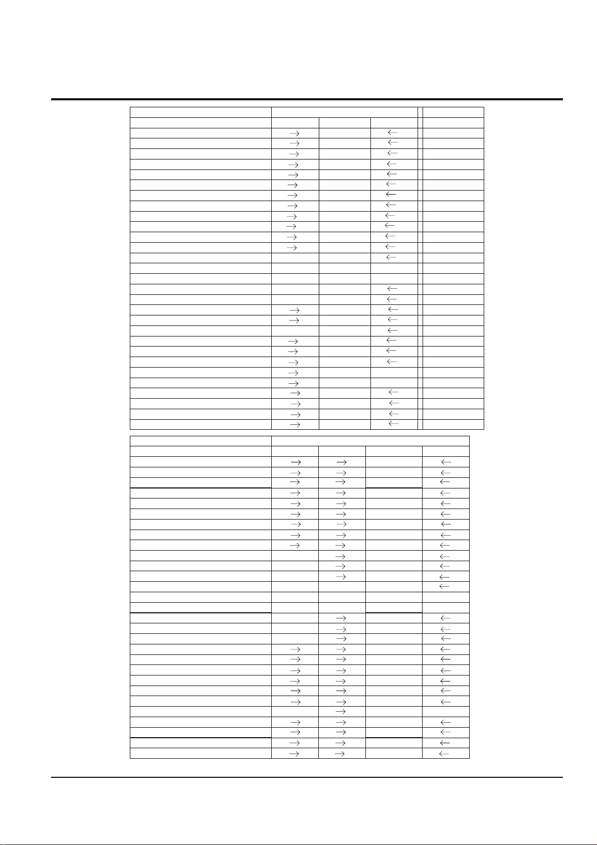
2-2 Chassis Product Specification
--
Acces sory Comment
-/--/ -
S-Cable / Scart Jack
Opt./Opt.Opt./Opt.
Carrying Case / Tape
SB-LS80
SB-LS80
Battery Pack
O/XO / XX/X
Remocon / Accessory Shoe
O-
Analog In
O/O/O/O/
Multi Lang./ Batt. Check/Instant On
O/GUI/OO/GUI/O
Beep Sound / Displ ay / PB Zoom
O/O/O/-O/O/O/-
AV / S.Jack / Ext.Mic / H.phone
O/ -/ O
Light / Nite Pix / LSS
6 scene
6 scene
JPEG Multi Display
X/X
X/X
Continuous Shot / Im age Mix
M4/D1/30fM4/D1/30f
MPEG Clip Form at / size / F.Ratio
SVGA
SVGA(800x600)
JPEG Recording Si ze to Memory
---
-
-
Memory Card
16M64M-
-
Builtin Memory
Multi
M.S
Memory Card Slot
MJ/Q/15fMJ/Q/15f
Web camera (For./size/F.rate)
M4/VG/15fM4/VG/15f
USB Stream. (For./size/F.Rate)
USB2.0USB2.0
USB
In/OutIn/Out
IEEE1394
DISDIS
Image Stabili zer
12/16b PCM12/16b PCM
Audio
ColorColor
Viewfinder
2.5", 123K2.5", 123K
LCD
680K680K
CCD
10x / 900x10x / 900x
Zoom/Digita l Zoom
520 line520 line
Resolution
MiniDVMiniDV
Format
VM-F830D457SC-D455D453
Model cod e
NTSC (
Rsx
)NTSC(America)
Region
Acces sory Comment
S-Cable / Scart Jack
Carrying Case / Tape
Battery Pack
X/X
Remocon / Accessory Shoe
-
Analog In
O/O/-
Multi Lang./ Batt. Check/Instant On
O/GUI/O
Beep Sound / Displ ay / PB Zoom
O/O/O/-
AV / S.Jack / Ext.Mic / H.phone
O/ - / O
Light / Nite Pix / LSS
6 scene
JPEG Multi Display
X/X
Continuous Shot / Im age Mix
M4/D1/12.5f
MPEG Clip Form at / size / F.Ratio
SVGA
JPEG Recording Si ze to Memory
-
---
Memory Card
64M
-
-
-
-
-
-
-
-
-
Builtin Memory
M.S.
Memory Card Slot
MJ/QQ/12.5f
Web camera (For./size/F.rate)
M4/VG/
USB Stream. (For./size/F.Rate)
USB2.0
USB
Out
IEEE1394
DIS
Image Stabili zer
12/16b PCM
Audio
Viewfinder
2.5", 123K
LCD
800K
CCD
10x / 900x
Zoom/Digita l Zoom
520 line
Resolution
MiniDV
Format
D455VP-D454D453D451
Model cod e
PAL (Europe)
Region
O
32M
- / - / O
- / - / O
Color
Multi
16M
-
/Opt.
SB-LS80
O/X
Opt.
O/Opt.
Multi
--
12.5
f
Product Specification
2-3
Samsung Electronics
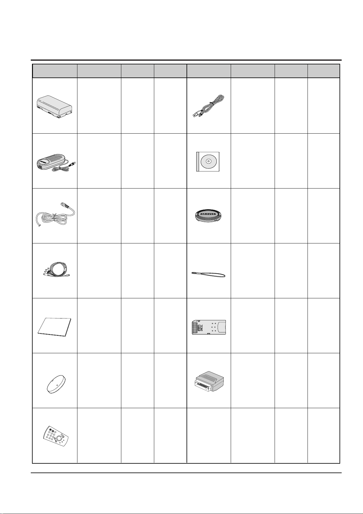
2-3 Accessories Supplied with Camcorder
(VP-D453(i),
VP-D454,
VP-D455(i)
only)
(VP-D453(i),
VP-D454,
VP-D455(i)
only)
(VP-D453(i),
VP-D454,
VP-D455(i)
only)
(VP-D453(i),
VP-D454,
VP-D455(i)
only)
(VP-D453(i),
VP-D454(i),
VP-D455(i)
only)
Basic
Basic
Basic
Basic
Basic
Basic
Basic
Basic
Basic
Basic
Basic
Accessories Description Part No Remark Description Part No RemarkAccessories
1. Lithium Ion
Battery Pack
AD43-00136A
AD43-00146A
Optional
Optional
2. AC Power Adapter
(AA-E8 TYPE)
AD44-00090A
AD68-00839G
5. Instruction Book
6. Lithium Battery
(CR2025)
AD43-10130H
7. Remote Control
AD59-00085A
AD97-07354B
8. USB Cable
AD39-00073A
AD46-00082A
AD46-00061A
9.Software CD
10. Lens Cover
11. Lens Cover strap
AD72-00049A
12. Memory Stick
3. AC
Cord
AD39-00078A
13. Scart Adapter
Model standard
of VP-D455/XEU
Model standard
of VP-D455/XEU
Model standard
of VP-D455/XEU
Model standard
of VP-D455/XEU
Model standard
of VP-D455/XEU
Model standard
of VP-D455/XEU
Model standard
of VP-D455/XEU
Model standard
of VP-D455/XEU
Model standard
of VP-D455/XEU
Model standard
of VP-D455/XEU
Model standard
of VP-D455/XEU
4. Multi-AV Cable
AD39-00119A

Product Specification
2-4
Samsung Electronics
MEMO
Samsung Electronics
3-1
3. Alignment and Adjustment
3-1 VCR Adjustment
3-1-1 Adjustment Preparation
1) Before you start
ΠUse the buttons on the CAMCORDER when adjusting VCR.
´ When changing the adjustment item, please press the “EASY-Q” and “DISPLAY” buttons on the
CAMCORDER.
ˇ The adjustment value can be changed by moving the “MENU Selector” Left or Right.
¨ Press the “MENU Selector” to store each adjustment into EEPROM.
ˆ The OSD shows “OK” after finishing each adjustment step.
Ø In order to exit the adjustment mode, disconnect the power source.
2) Function of each buttons on the Set Key
Buttons Description
MENU Selector push (Confirm) Stores changed value in the adjustment and auto adjustment mode.
MENU Selector Right (Data Up)
Changes data in the adjustment state.
MENU Selector Left (Data Down)
EASY-Q (Mode Up)
Changes mode.
DISPLAY (Mode Down)
<Table 3-1>
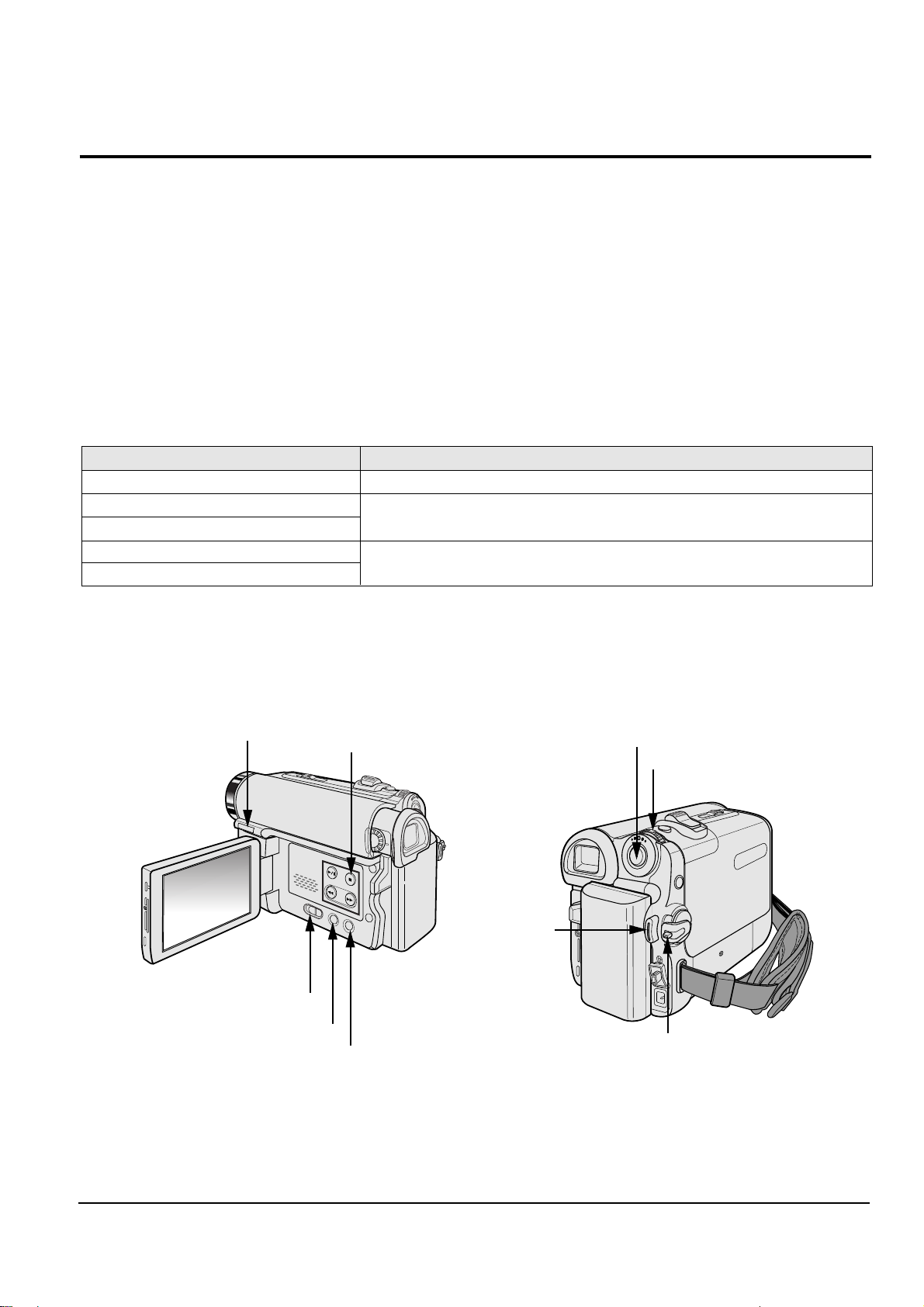
3) How to get into the VCR adjust mode
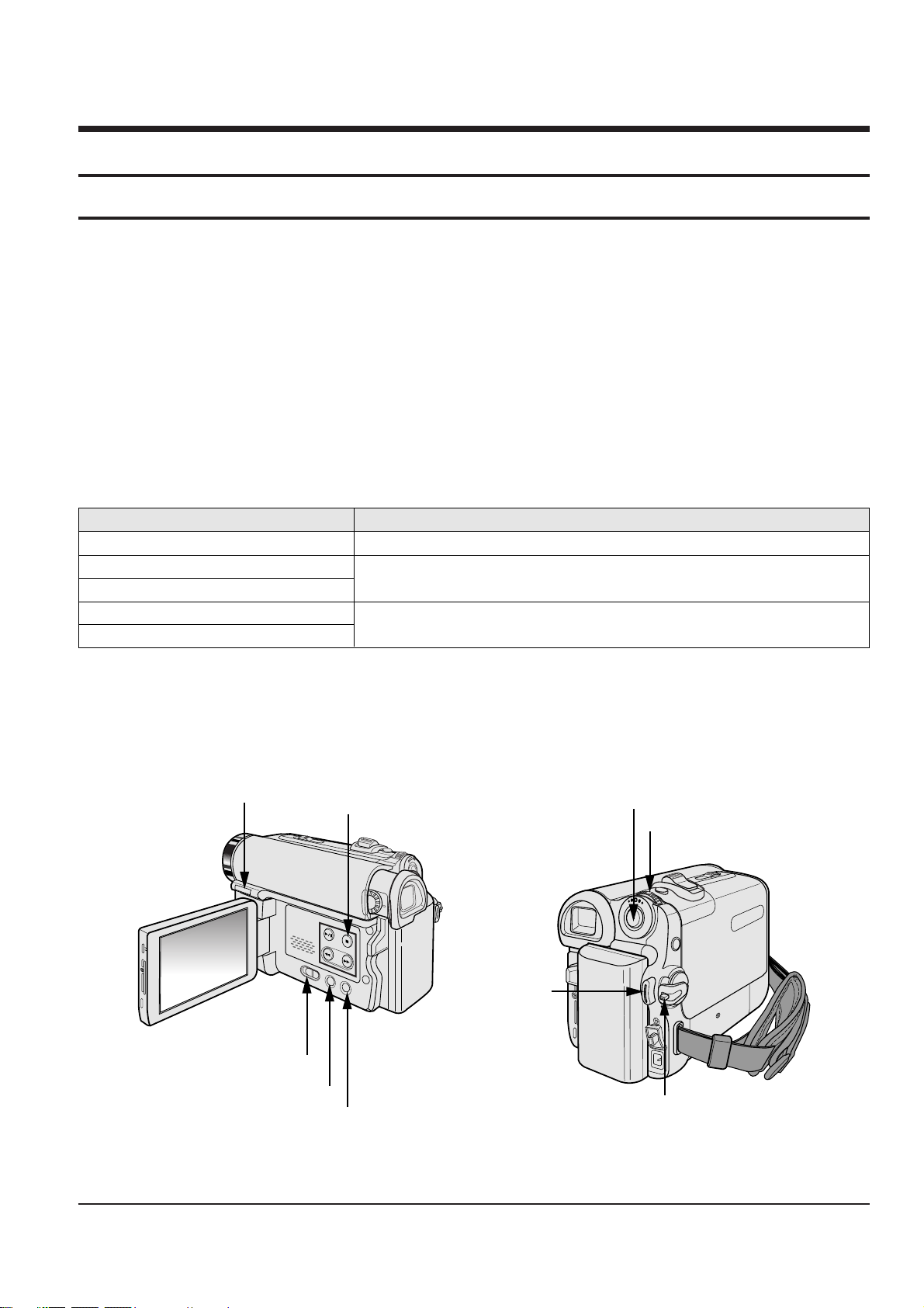
[STEP 1]
ΠConnect the Power source.
´ Set the Power Switch to “PLAYER” position and Mode Switch to “TAPE” position.
Fig. 3-1
MENU Button
EASY Q Button
Start/Stop Button
MENU Selector
DISPLAY Button
Mode switch
PB ZOOM
Power switch
STOP Button
3-2
Alignment and Adjustments
Samsung Electronics
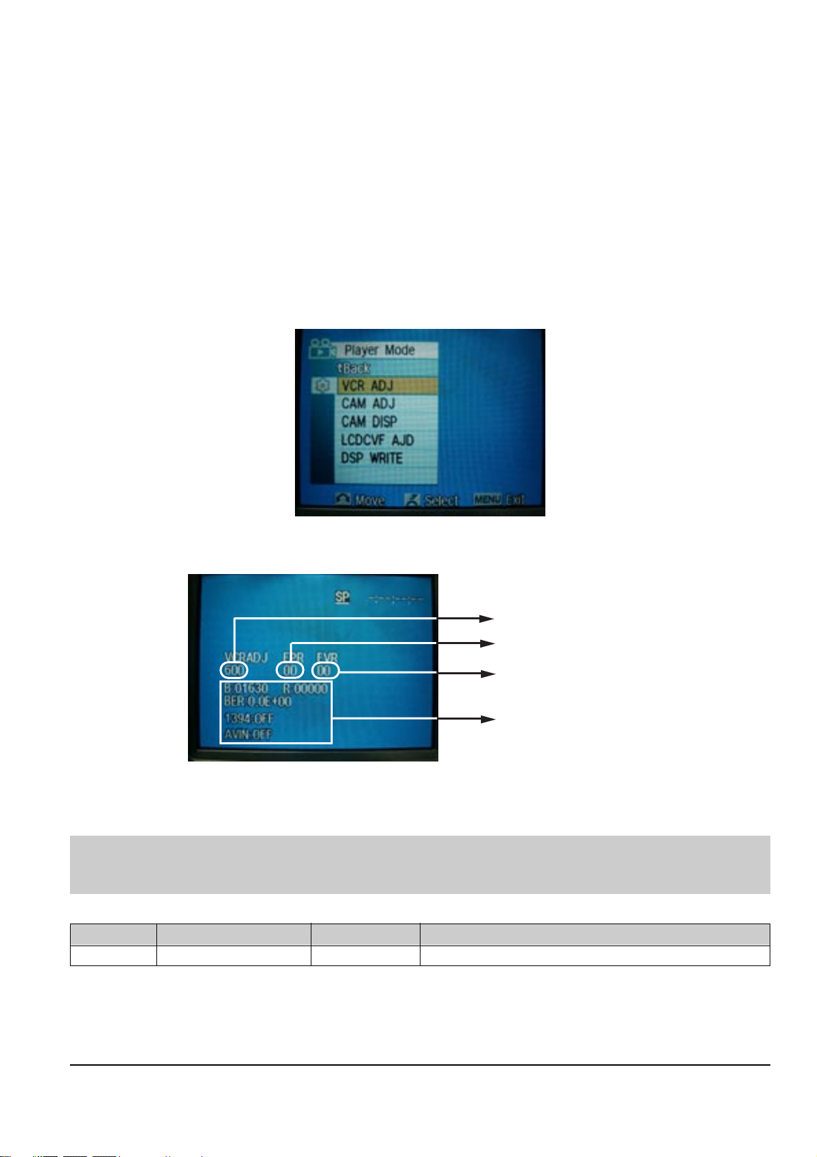
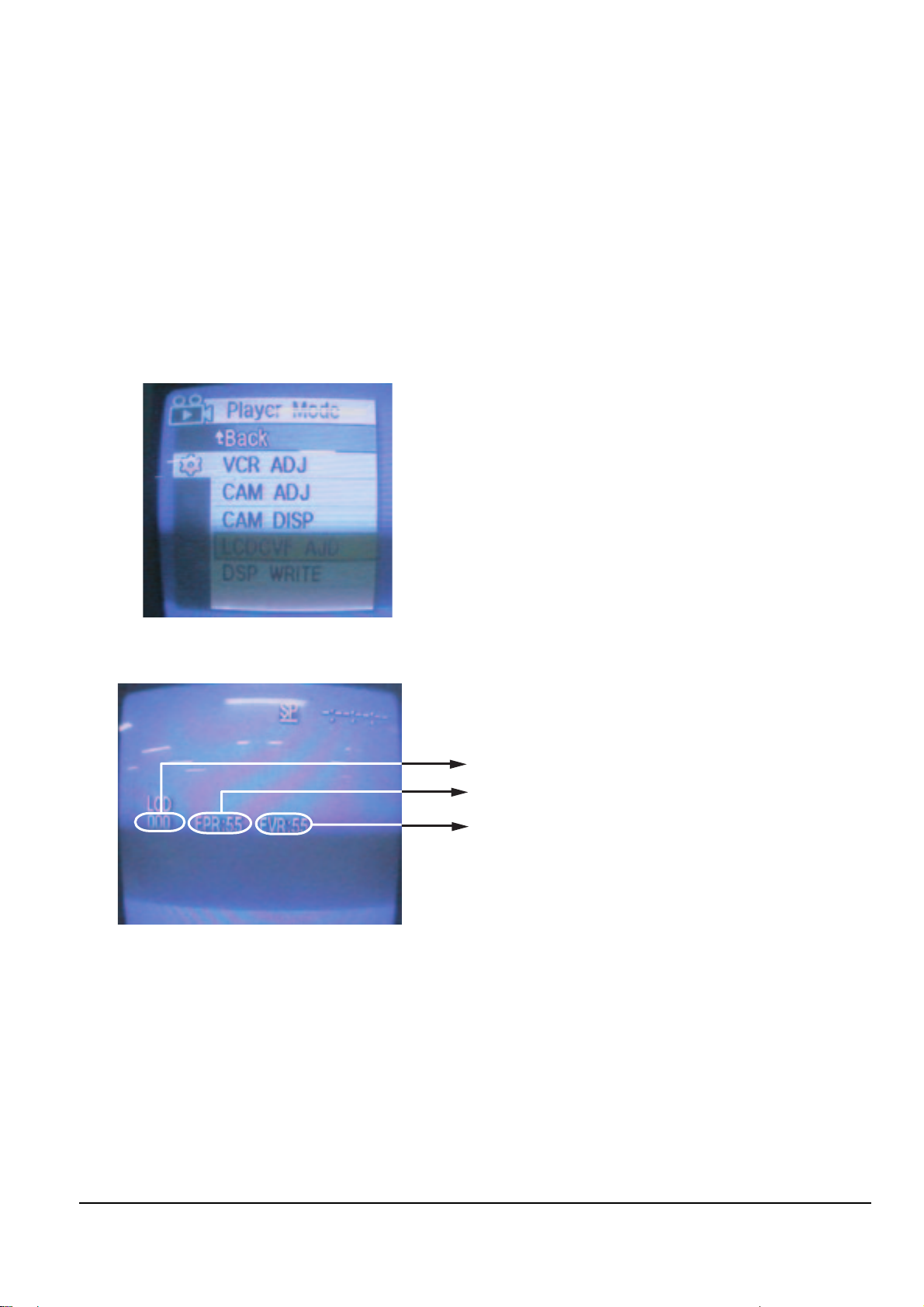
[STEP 2]
ΠPress and hold the "STOP" and "PB ZOOM" buttons on the video camera at the same time for more than
5 seconds.
´ When monitor OSD appears as shown Fig. 3-2, the adjustment mode has been activated successfully.
ˇ Move the “MENU Selector” to highlight VCR ADJ and push the “MENU Selector”.
¨ Monitor OSD shows Fig. 3-3.
Then VCR adjustment mode has been activated successfully.
[STEP 3]
In order to complete the adjustment the power must be reset.
This can be done by disconnecting and reconnecting the power source.
Fig. 3-2
Indicates current adjustment item
Adjustment value
For Engineering Mode
Stored value
Fig. 3-3
3-1-2 VCR Adjustment
ΠGet into VCR ADJUST mode.
´ Move to the VCR ADJUST address “6IF”.
ˇ Play standard tape, and “Head Switching Position” will be adjusted automatically (within 5 Seconds).
Mode
(Address)
Name Value Description
61F SWP Position 80 Head Switching Position Adjust
<Table 3-2>
Note : This is the only electronic adjustment for the VCR.
Other addresses have already been assigned data during the manufacturing process.
We don’t need any adjustment for those addresses.

Alignment and Adjustments
3-3
Samsung Electronics
3-2 Camera Adjustment
Note : How to adjust the camera system.
1) EEPROM stores confirmed adjustment value of each adjustment step.
2) DSP (Digital Signal Process : ICM01-Main PCB) digitalizes the camera signal.
3) When changing IC505-Main PCB of EEPROM, readjust Main PCB.
While changing LCD PCB and CVF PCB- always readjust each part.
Since EEPROM stores confirmed adjustment value of each adjustment step, readjusting must be performed in order
to store the changed data.
4) Adjust the following items after changing LENS Ass’y.
ΠLens Zoom Track
´ Auto HALL
ˇ Auto IRIS
5) Adjust the following items after changing EEPROM and Camera Main PCB.
ΠLens Zoom Track
´ Zoom VR Center
ˇ Auto HALL
¨ Auto IRIS
ˆ Auto White Balance (indoor)
Ø Auto White Balance (outdoor)
3-2-1 Adjustment Preparation
1) Before you start
ΠUse the buttons on the CAMCORDER when adjusting Camera.
´ When changing the adjustment item, please press the “EASY-Q” and “DISPLAY” buttons on the
CAMCORDER.
ˇ The adjustment value can be changed by moving the “MENU Selector” Left or Right.
¨ Press the “MENU Selector” to store each adjustment into EEPROM.
ˆ The OSD shows “OK” after finishing each adjustment step.
Ø In order to exit the adjustment mode, disconnect the power source.
2) Function of each buttons on the Sst Key
Buttons Description
MENU Selector push (Confirm) Stores changed value in the adjustment and auto adjustment mode.
MENU Selector Right (Data Up)
Changes data in the adjustment state.
MENU Selector Left (Data Down)
EASY-Q (Mode Up)
Changes mode.
DISPLAY (Mode Down)
<Table 3-3>
3-4
Alignment and Adjustments
Samsung Electronics
5) How to set up the camera adjustment mode
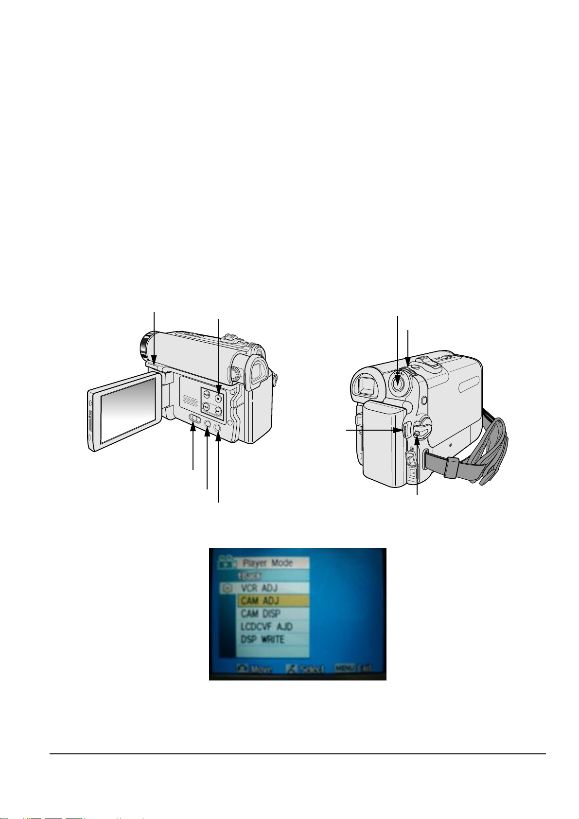
[STEP 1]
ΠConnect the Power source.
´ Set the Power Switch to “CAM” position and Mode Switch to “TAPE” position.
[STEP 2]
ΠPress and hold the "STOP" and "PB ZOOM" buttons on the video camera at the same time for more than
5 seconds.
´ When monitor OSD appears as shown Fig. 3-5, the adjustment mode has been activated successfully.
ˇ Move the “MENU Selector” to highlight CAM ADJ and push the “MENU Selector”.
¨ Monitor OSD shows Fig. 3-6.
Then Camera adjustment mode has been activated successfully.
[STEP 3]
In order to complete the adjustment the power must be reset.
This can be done by disconnecting and reconnecting the power source.
Fig. 3-5
Fig. 3-4
MENU Button
EASY Q Button
Start/Stop Button
MENU Selector
DISPLAY Button
Mode switch
PB ZOOM
Power switch
STOP Button
Alignment and Adjustments
3-5
Samsung Electronics
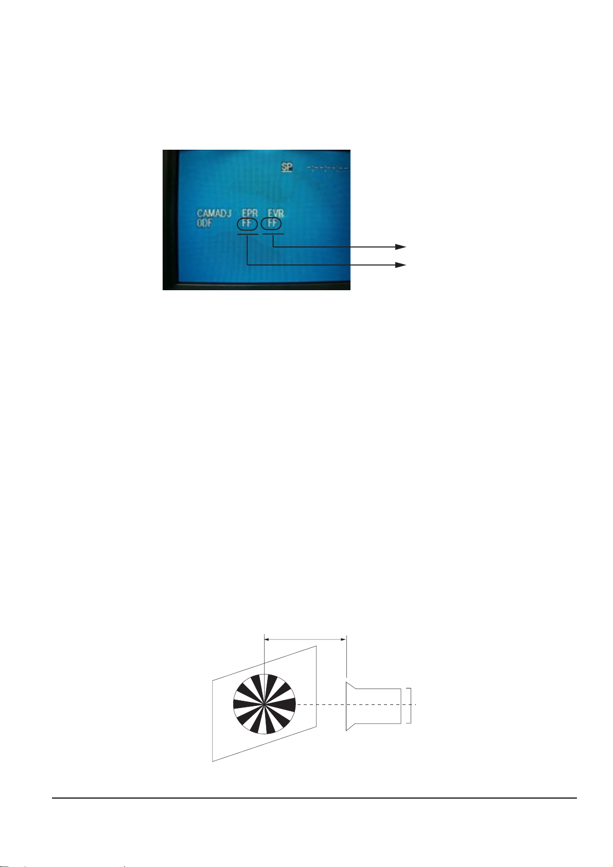
3-2-2 Camera Adjustment
Note : "XX XX" indicate the previous preset value and adjusted value.
Press the “MENU Selector” (Confirm) to store the adjusted value.
Adjusted values
Stored values
Fig. 3-6
1) EEPROM Data Initialize
Caution : These adjustments must be done when installing a new EPROM (IC105) or Main PCB.
Œ Press the “EASY-Q”(Mode Up)/”DISPLAY”(Mode Down) buttons until CAMADJ displays “0DF XX XX”.
´ Use the “MENU Selector” (Data Up/Down) until the display data for EVR is “A0”.
ˇ Press the “MENU Selector” (Confirm).
¨ The OSD shows “OK” after finishing the initalize.
2) Lens Zoom Track
Caution : For whole zoom range, it shall be in focus.
The location of a focus lens is moving depending on the location of Zoom Lens.
During adjusting, micom measures the focus location from a near distance to a long.
ΠCamera is set to E-E mode.
´ Focus chart photo.
ˇ Center the camera about 3m from a focus chart which, should be placed on a flat surfaced white or gray wall.
¨ Connect the video output terminal to a TV.
ˆ Press the “EASY-Q” (Mode Up)/”DISPLAY” (Mode Down) buttons until CAMADJ displays “0DE XX XX”.
Ø Press the “MENU Selector” to begin adjustment.
The camera must be kept still when adjusting the zoom and focus lens.
If you don’t have any chart, you can use the object which has a lot of vertical line.
The OSD shows “OK” after finishing the adjustment.
(The word “OK” is displayed for only a fraction of a second.)
Fig. 3-7
3M ± 1cm
(Be sure to maintain the distance)
CCDLENS

3-6
Alignment and Adjustments
Samsung Electronics
3) Zoom VR Center
ΠConnect a video output terminal to a TV.
´ Press the “EASY”(Mode Up)/”DISPLAY”(Mode Down) buttons so that OSD shows “0D6 XX XX”.
ˇ Press the “MENU Selector” (Confirm).
¨ Then Micom finds out Zoom VR center position.
Store Zoom VR center value in OB7.
4) Auto HALL
ΠConnect a video output terminal to a TV.
´ Press the “EASY-Q”(Mode Up)/”DISPLAY”(Mode Down) buttons so that OSD shows "0CD XX XX".
ˇ Press the “MENU Selector” (Confirm).
¨ Then micom finds out max. Hall value with an iris opened and min. Hall value with an iris closed.
Store max. and min. value of Hall in OAD and OAC respectively.
ˆ The OSD shows “OK” after finishing the adjustment.
(The word “OK” is displayed for only a fraction of a second.)
5) Auto IRIS Level
ΠConnect a video output terminal to a wave form monitor and a TV.
´ Press the “EASY-Q”(Mode Up)/”DISPLAY”(Mode Down) buttons so that OSD shows "0CE XX XX".
ˇ Press the “MENU Selector” (Confirm).
¨ Then micom finds out max. Hall value with an iris opened and min.
Hall value with an iris closed. Store max. and min. value of in 00BC, 00BD and 00BB respectively.
ˆ The OSD shows “OK” after finishing the adjustment.
(The word “OK” is displayed for only a fraction of a second.)
6) Auto White Balance (indoor)
Œ Camera mode & 3100˚ K gray scale chart.
´ Connect a video output terminal to a vectorscope and a TV.
ˇ Press the “EASY-Q”(Mode Up)/”DISPLAY”(Mode Down) buttons so that OSD shows "0D4 XX XX".
¨ Ensure that camera picks up image 40µs on 3100˚K gray scale chart precisely and the illumination is
1500~2000 Lux.
ˆ Press the “MENU Selector” (Confirm) to ensure that white spot on a vectorscope is moving in the middle of
screen.
Ø The OSD shows “OK” after finishing the adjustment.
(The word “OK” is displayed for only a fraction of a second.)
7) Auto White Balance (outdoor)
Œ Camera mode & 5100˚ K gray scale chart.
´ Connect a video output terminal to a vectorscope and a TV.
ˇ Press the “EASY-Q”(Mode Up)/”DISPLAY”(Mode Down) buttons so that OSD shows "0D5 XX XX".
¨ Ensure that camera picks up image 40 µs on 5100 gray scale chart (3100 gray scale chart + C16 filter) precisely
and the illumination is 1500~2000 Lux.
ˆ Press the “MENU Selector” (Confirm) to ensure that white spot on a vectorscope is moving in the middle of
screen.
Ø The OSD shows “OK” after finishing the adjustment.
(The word “OK” is displayed for only a fraction of a second.)
Alignment and Adjustments
3-7
Samsung Electronics
3-3 LCD Adjustment
3-3-1 Adjustment Preparation
1) Before you start
ΠUse the buttons on the CAMCORDER when adjusting LCD.
´ When changing the adjustment item, please press the “EASY-Q” and “DISPLAY” buttons on the
CAMCORDER.
ˇ The adjustment value can be changed by moving the “MENU Selector” Left or Right.
¨ Press the “MENU Selector” to store each adjustment into EEPROM.
ˆ The OSD shows “OK” after finishing each adjustment step.
Ø In order to exit the adjustment mode, disconnect the power source.
2) Function of each buttons on the Set Key
Buttons Description
MENU Selector push (Confirm) Stores changed value in the adjustment and auto adjustment mode.
MENU Selector Right (Data Up)
Changes data in the adjustment state.
MENU Selector Left (Data Down)
EASY-Q (Mode Up)
Changes mode.
DISPLAY (Mode Down)
<Table 3-4>
3) How to get into the LCD adjust mode
[STEP 1]
ΠConnect the Power source.
´ Set the Power Switch to “PLAYER” position and Mode Switch to “TAPE” position.
Fig. 3-8
MENU Button
EASY Q Button
Start/Stop Button
MENU Selector
DISPLAY Button
Mode switch
PB ZOOM
Power switch
STOP Button
3-8
Alignment and Adjustments
Samsung Electronics
[STEP 2]
ΠPress and hold the "STOP" and "PB ZOOM" buttons on the video camera at the same time for more than
5 seconds.
´ When monitor OSD appears as shown Fig. 3-9, the adjustment mode has been activated successfully.
ˇ Move the “MENU Selector” to highlight VCR ADJ and push the “MENU Selector”.
¨ Monitor OSD shows Fig. 3-10.
Then VCR adjustment mode has been activated successfully.
[STEP 3]
In order to complete the adjustment the power must be reset.
This can be done by disconnecting and reconnecting the power source.
Fig. 3-9
Fig. 3-10
Indicates current adjustment item
Adjustment value
Stored value
Alignment and Adjustments
3-9
Samsung Electronics
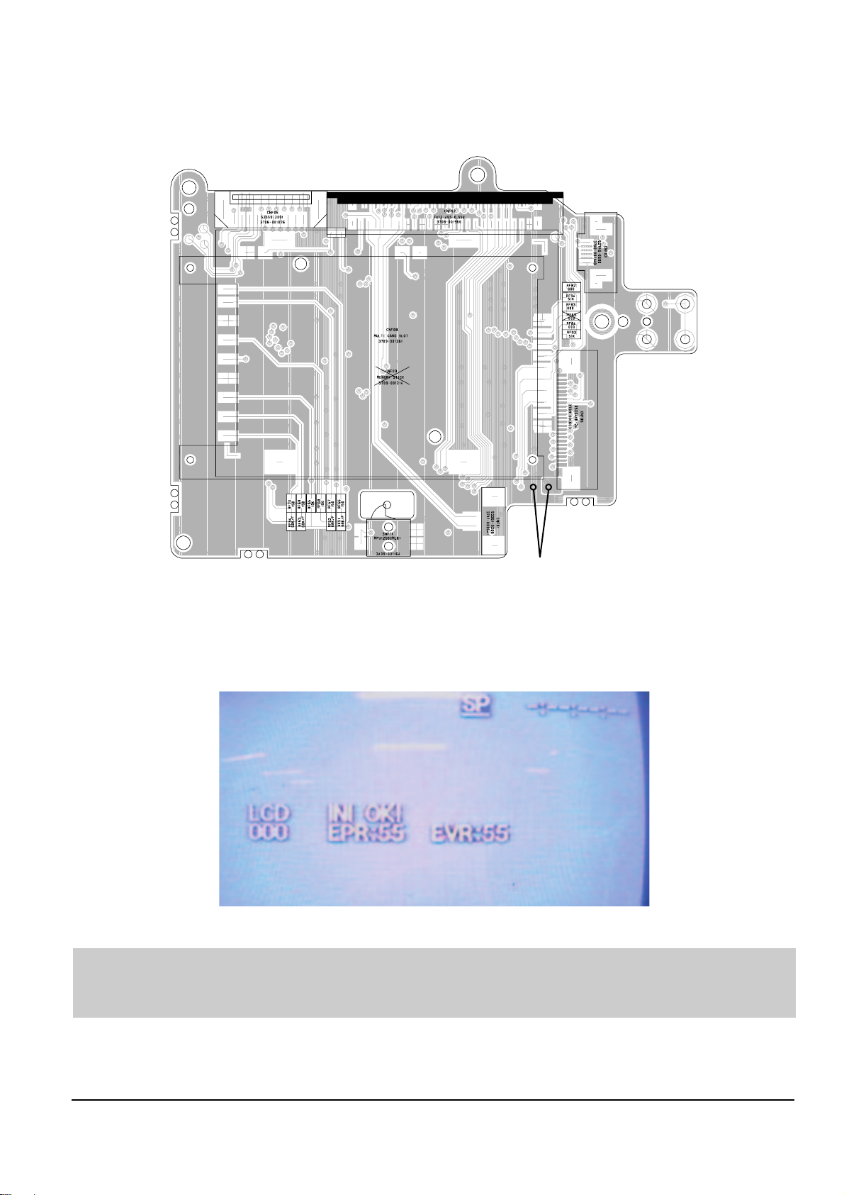
3-3-2 LCD Adjustment
Short Point
Fig. 3-11 Location of Test point (Function PCB)
1) Initial Adjustment
ΠLet two solder lands short. (Refer to Fig. 3-11, two short point)
´ Press a “STOP” button for 3 seconds or more until “INT OK” appears. (See Fig. 3-12)
Fig. 3-12
◆ You continuously let two solder lands short until completing all adjustment (from 1] Initial Adj. to 7] VCO Adj.)
and they must be opened after completing all adjustment.
◆ If two solder lands are continuously shorted, the product doesn’t work correctly.

3-10
Alignment and Adjustments
Samsung Electronics
TV SIGNAL
MODE
NTSC PAL
TRANSMISSION TRANS-Reflective TRANSMISSION TRANS-Reflective
00 55 55 55 55
01 80 80 80 80
02 CD CD CD CD
03 B0 B0 B0 B0
04 95 95 95 95
05 1F 1F 1F 1F
06 5A 5A 5A 5A
07 40 40 40 40
08 00 00 00 00
09 40 40 40 40
0A 90 90 90 90
0B 2A 2A 2A 2A
0C 30 30 30 30
0D A1 A1 A1 A1
0E 4C 4C 4C 4C
0F 10 10 00 0 00 0
10 05 05 05 05
11 11 11 11 11
12 00 00 01 01
13 04 04 04 04
14 2D 2D 2D 2D
15 D7 D7 D7 D7
16 2C 2C 2C 2C
1D 85 85 85 85
1E 02 02 02 02
1F 02 02 02 02
20 2A 2A 2A 2A
21 02 02 02 02
22 02 02 02 02
<Table 3-5>
Alignment and Adjustments
3-11
Samsung Electronics
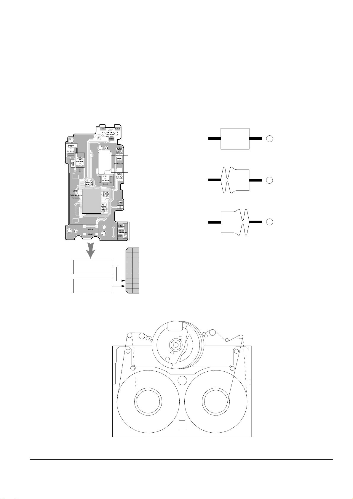
3-4 Deck Adjustment
3-4-1 Operation Without Housing Assembly
1) Remove the Housing Ass’y from the Deck Ass’y.
2) Connect the Mechanical Chassis to the recorder
circuit to supply voltage.
3) Set to Unload mode.
4) Press the S/W Push (Keep ON status)to start loading, and push the PLAY Key.
(Cover the Top/End sensor with black tape,
because they do not operate.)
Note : For the removal of the Housing Ass’y refer to
4-2-2 (page 4-6).
Connceted the Recorder Circuit
SWITCH C-IN
Fig. 3-13
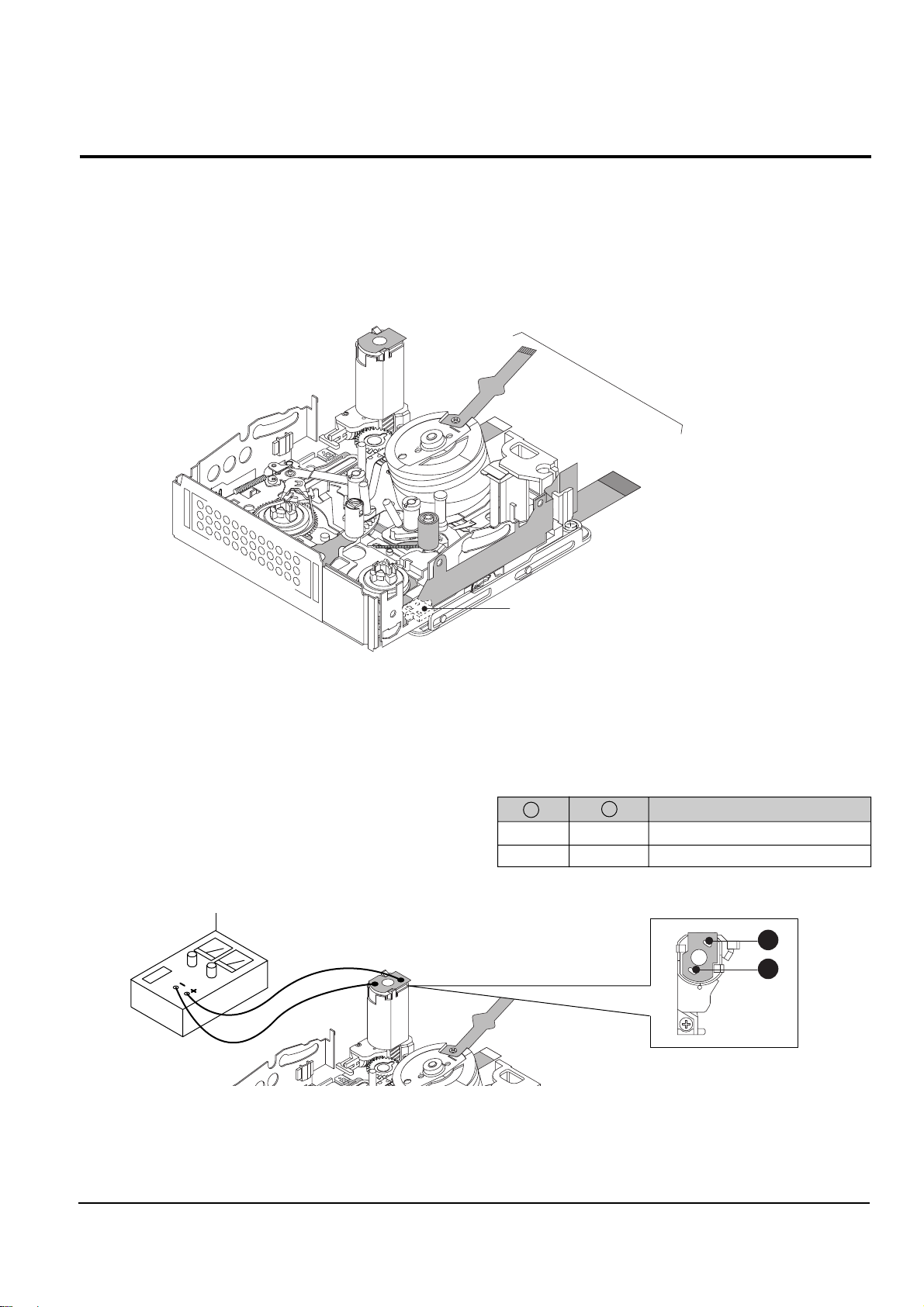
3-4-2 Setting Mechanical Mode (Without Recorder Circuit)
1) Set the power-supply output to approx. 3V~5V.
2) Choose the polarity (depending on whether loading or unloading).
3) Supply the voltage to the Motor Loading, and set
to the desired mode.
Fig. 3-14
A
B
DC POWER SUPPLY
<Table 3-6>
AB Movement of Chassis
+- Unloading
-+ Loading
3-12
Alignment and Adjustments
Samsung Electronics
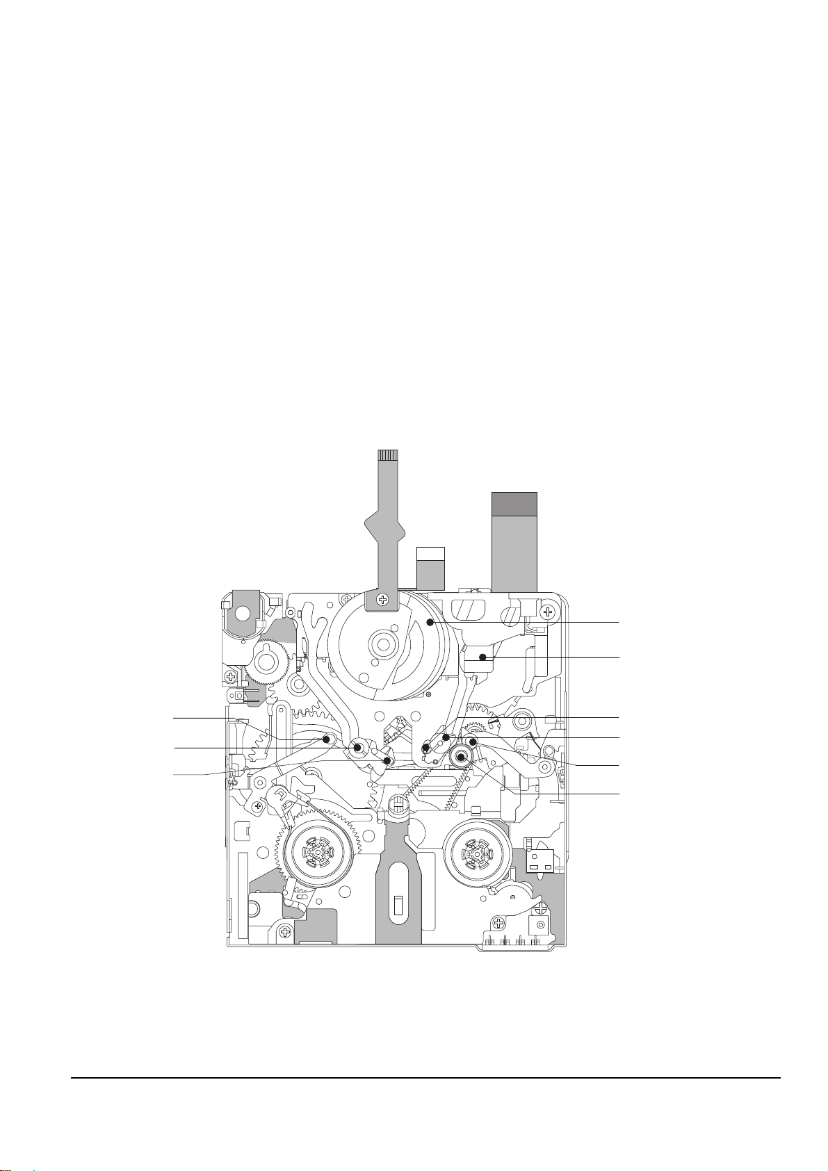
3-4-3 Maintenance
Carry out the following periodic maintenance checks in order to fully exercise all functions, operations and tape.
After repairing, service the set as follows:
1) Cleaning of Drum Assembly
ΠGently apply lens tissue soaked in ethyl alcohol to the Drum assembly.
Clean the Upper Drum assembly while rotating it slowly counterclockwise(by hand).
Note : Do not rotate the motor by power or rotate the Upper Drum assembly clockwise.
Also, the Head tip will be damaged if the lens tissue is moved in a perpendicular direction.
Be sure to follow these instructions when cleaning the Drum Ass’y
2) Cleaning of Tape Path
ΠIn EJECT mode, clean the tape path system(from Pole Tension P1 through Pole Review P8, Pinch Roller and
Capstan Shaft) and the Lower Drum. Using the lens tissue soaked in ethyl alcohol.
Note : Make sure that no oil or grease adheres to the lens tissue.
Fig. 3-15
P1
P2
P3
P4
P7
P5
P6
P8
PINCH ROLLER
Alignment and Adjustments
3-13
Samsung Electronics
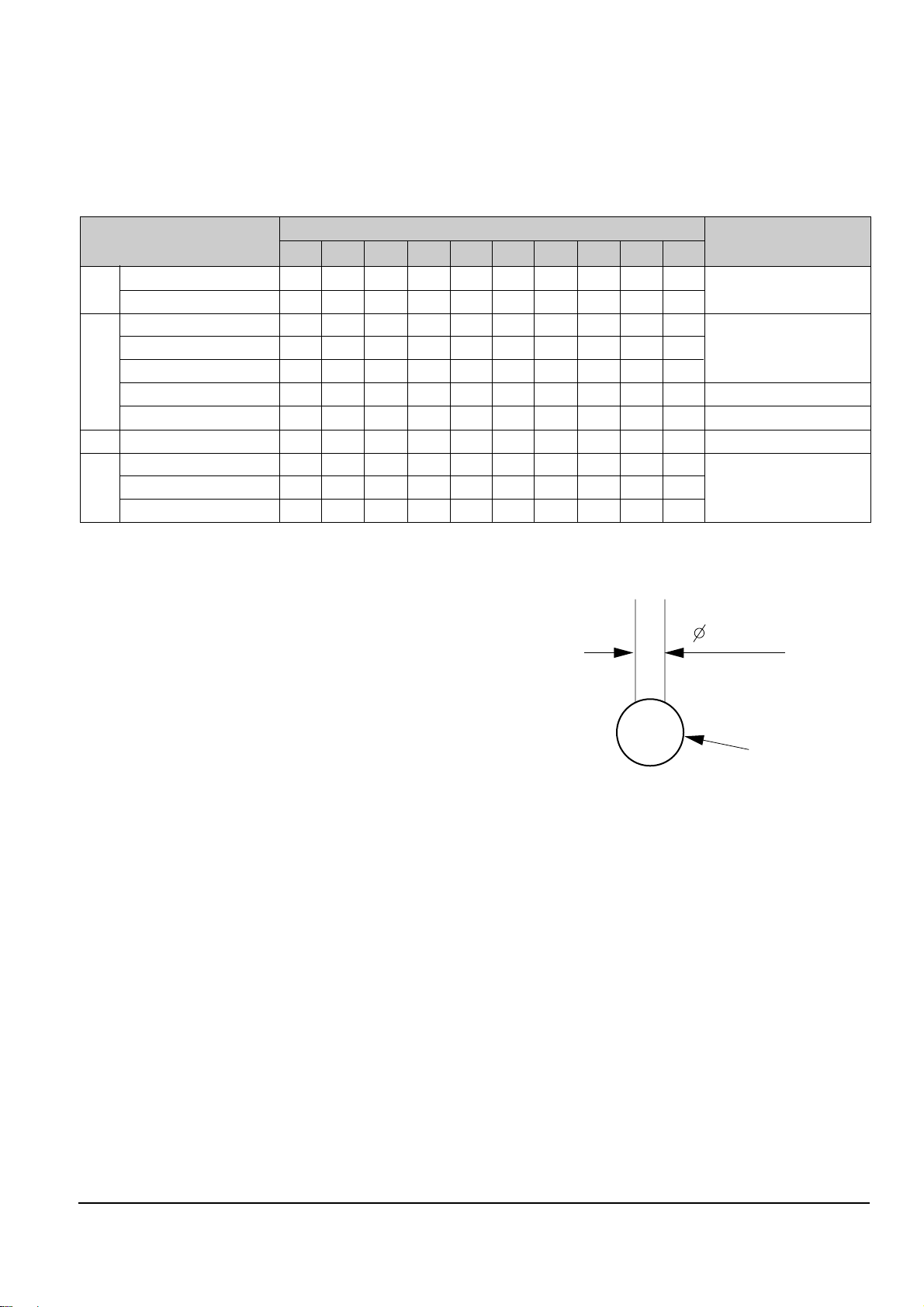
3) Periodic Maintenance and Check List
When overhauling, refer to the following table.
2mm
OIL
◆ When lubrication bearings, be sure to keep the oil
free of dust. (Oil contaminated with dust might
cause the bearings to wear out or seize.)
◆ A “drop”of oil is defined as the amount attached to
the tip of a Ø 2mm stick as shown in Fig. 3-16.
<Table 3-7>
Fig. 3-16
O : Cleaning ∆ : Oil ◆ : Confirmation
Tape
path
system
D
R
I
V
I
N
G
S
Y
S
T
E
M
- Never let oil get on to the tape path
surface.
Maintenance checks
Hours of use (H)
Remark
500 1000 1500 2000 2500 3000 3500 4000 4500 5000
Cleaning of tape path O O O O O O O O O O
Cleaning and degaussing of drum ass’y
OOOOOOOOOO
Capstan Shaft ∆∆∆∆∆
Gear Capstan ∆∆∆∆∆
Gear Pully Shaft ∆∆∆∆∆
Belt Timing ◆◆◆◆◆
Motor Loading ◆◆◆◆◆
Abnormal Noise ◆◆◆◆◆◆◆◆◆
Back Tension ◆◆◆◆◆
Brake System ◆◆◆◆◆
PB, REV Torque Measurement
◆◆◆◆◆
Confir-
mation
Perform-
ance
3-14
Alignment and Adjustments
Samsung Electronics
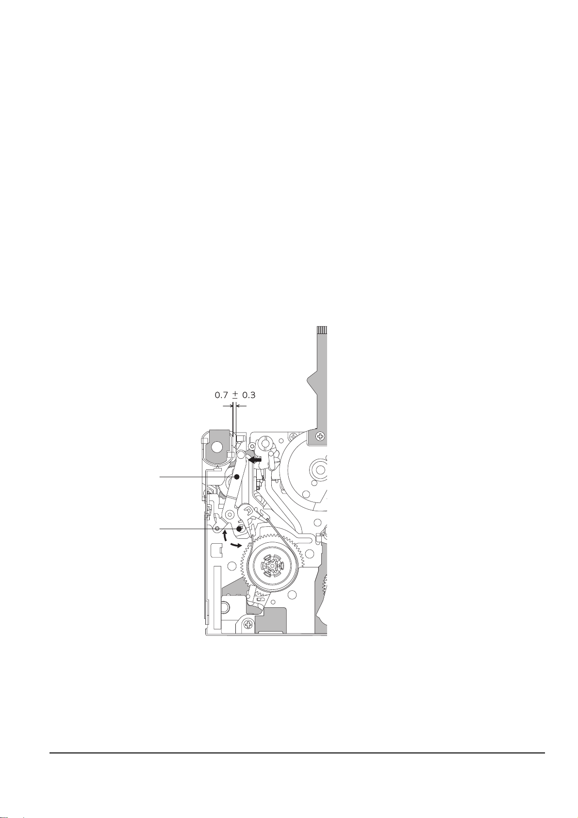
3-4-4 Mechanical Check and Adjustment
3-4-4(a) Tension Regulator Adjustment
1) Disassembly
Œ For the removal of the Housing Ass’y refer to 4-2-2 (page 4-6).
2) Adjustment
ΠSet to PLAY mode (without cassette tape).
´ Check that the distance between external surface of Holder Loading and extenal diamater of Arm Tension is
0.7±0.3mm. (Fig. 3-17)
ˇ If necessary, proceed to step 4.
¨ If the Arm Tension Œ is located inside (or right) the position specified, adjust the Cap Adjust Œ toward
arrow “A”. (If it is located outside (or left), adjust toward arrow “B”.)
Note : Check if the Arm Tension can be moved toward arrow “C” in PB mode.
3) Reassembly
Œ For the removal of the Housing Ass’y refer to 4-2-2 (page 4-6).
Fig. 3-17
ARM TENSION Œ
CAP ADJUST ´
"A"
"B"
"C"
Alignment and Adjustments
3-15
Samsung Electronics
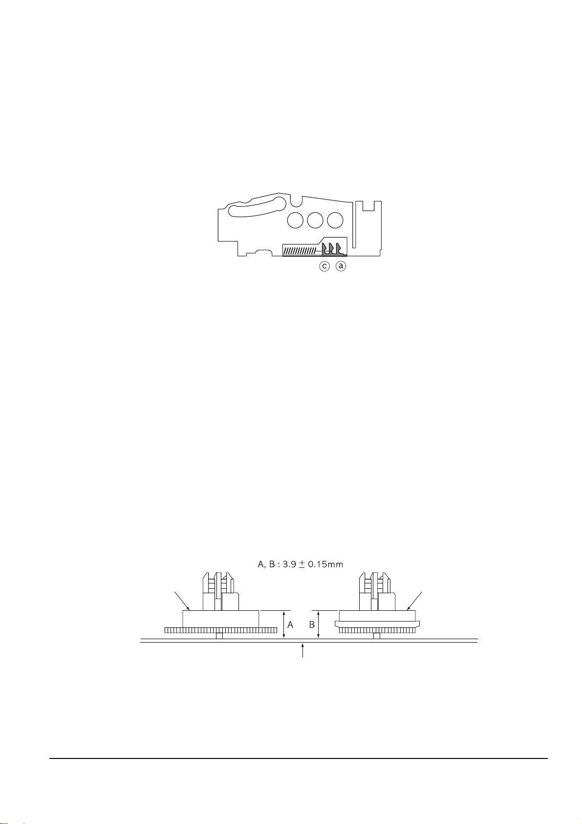
3-4-4(b) Back Tension Confirmation
1) Set up the cassette-torque tape.
2) Set to CAMERA mode, push the EDIT(+) KEY and check that the torque value of Reel S is 5.5±1g.cm.
3) If necessary, proceed to step 4.
4) If the Tension value is Low specified, moved to toward “a”.
If the Tension value is High specified, moved to toward “c”.
Reference : After changed, insert Cassette torque tape and confirm torque value.
Fig. 3-19
REEL DISK S TABLE
RESTING SURFACE
REEL DISK T TABLE
RESTING SURFACE
CHASSIS SUB
Fig. 3-18
3-4-4(c) PB/REV Torque check
1) Set up the cassette torque tape.
2) Set to CAMERA mode, Push the EDIT(+) button and check that the torque value of Reel T is 9±3g.cm.
3) Push the EDIT(-) button and check that the torque value of Reel S is 15±3g.cm.
4) If necessary, replace the defective Reel Disk S, T Ass’y.
3-4-4(d) Reel Table Height Check
1) Removal
Œ For the removal of the Housing Ass’y refer to 4-2-2 (page 4-6).
´ For the removal of the Idler Ass’y refer to 4-2-3 (page 4-7).
2) Check
ΠUsing vernier calipers, check the following distances : From the upper surface of the Sub Chassis to the
resting surfaces of Reel S, T table should each be 3.9±0.1mm.
3) Mounting
Œ For the removal of the Idler Ass’y refer to 4-2-3 (page 4-7).
´ For the removal of the Housing Ass’y refer to 4-2-2 (page 4-6).
3-16
Alignment and Adjustments
Samsung Electronics
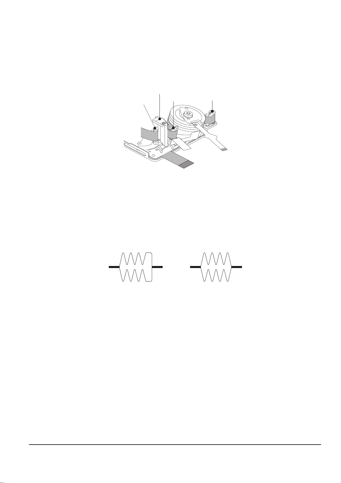
3-4-5 Tape Path Adjustment
3-4-5(a) Preparation for Adjustment
ΠClean the tape running surface (Poles, Drum, Capstan Shaft, Pinch Roller).
´ Observe the PB RF signal and Head Switching Pulse on an oscilloscope.
ˇ Play back the alignment tape.
¨ Check that the waveform of the RF signal is flat at both inlet and outlet(A in Fig. 3-21).
If not flat (B or C in Fig. 3-21), do adjustments 3-4-5(b) through 3-4-5(d).
RF Signal
(Pin 3 of CNR02)
Head Switching
(Pin 2 of CNR02)
1
2
3
4
5
6
7
8
910
11
12
13
14
15
16
17
18
CNR02
Fig. 3-20 Rear PCB (Bottom Side)
P1
P2
P5
P6
P7
P8
P3
Fig. 3-22
A
B
C
INLET OUTLET
NORMAL
DEFECT AT INLET
DEFECT AT OUTLET
Fig. 3-21
Alignment and Adjustments
3-17
Samsung Electronics
3-4-5(b) Tracking adjustment
ΠPlay Back the alignment tape.
´ Turn P3 to flatten the waveform at the inlet.
ˇ Turn P5 to flatten the waveform at the outlet.
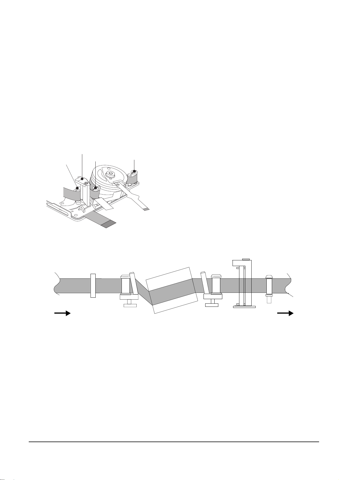
3-4-5(c) Take Up Path Adjustment
ΠPlay back the alignment tape, and confirm that the tape is not twisted between the Guide Roller T and
Capstan. (If the tape is twisted, turn P8, Fig. 3-23)
´ Set to REV mode and observe the outlet waveform of PB RF signal. (Fig. 3-24)
ˇ If the outlet waveform is out-of-spec, turn P8 counterclockwise, and redo steps 1 and 2.
P8
P6
MOTOR CAPSTAN
P2
Fig. 3-23
(DEFECTIVE) (CORRECT)
Fig. 3-24
3-18
Alignment and Adjustments
Samsung Electronics
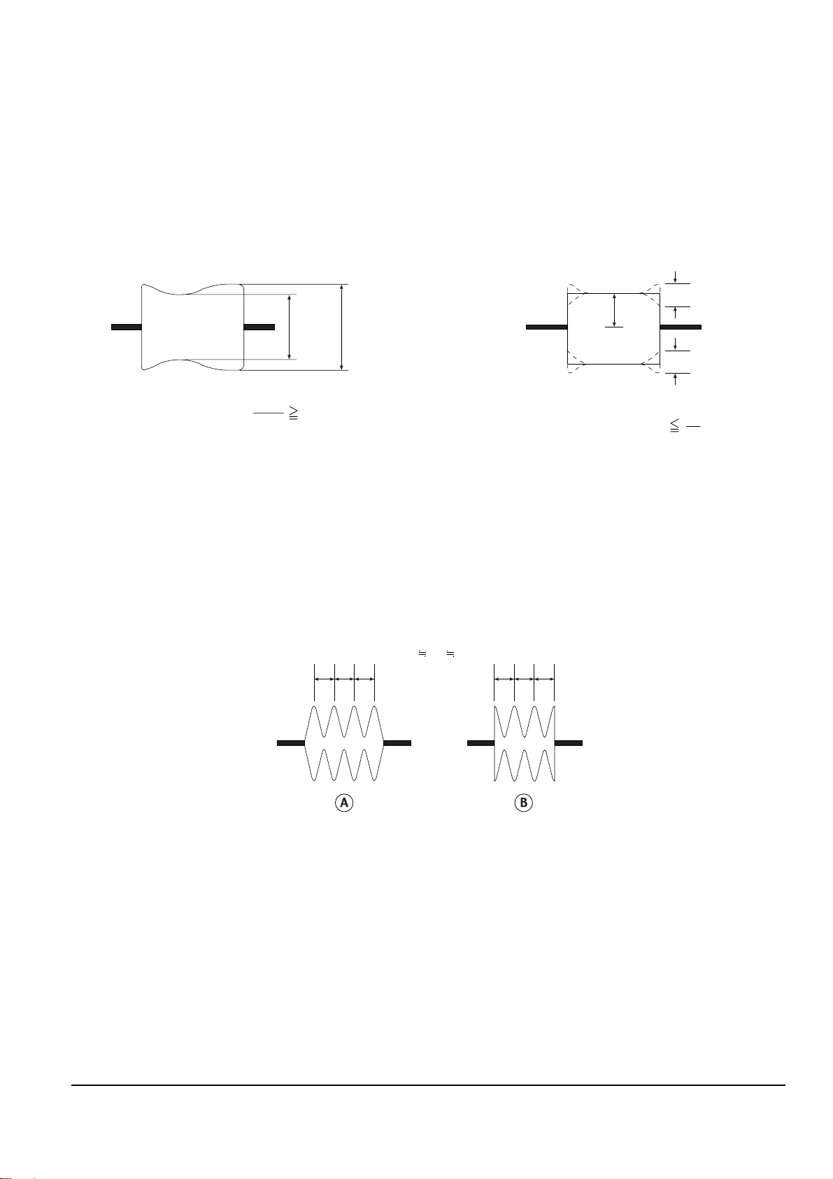
3-4-5(d) Check After Adjustment
1) Tracking Check
ΠPlayback the alignment tape.
´ Confirm that the minimum amplitude value(E min.)is 80% of the maximum value(E max.) or larger.
(Fig. 3-25)
ˇ Confirm that no large fluctuation occur on the waveform. (Fig. 3-26)
2) CUE and REV Check
ΠPlayback the alignment tape, and set to REV mode.
Confirm that the waveform peaks have a uniform Pitch. (Fig. 3-27 A)
If the track pitch is not uniform, do section 3-4-5(b) (Tracking adjustment) and 3-4-5(c) (P8 adjustment).
´ Set to CUE mode.
Confirm that the waveform peaks still have a uniform pitch. (Fig. 3-27 B)
If the track pitch is not uniform, do section 3-4-5(b) (Tracking Adjustment).
Emin Emax
Emax
Emin
80(%)
Fig. 3-25
A
A
C
C
C
1
8
Fig. 3-26
abc a
abc
bc
Fig. 3-27
Alignment and Adjustments
3-19
Samsung Electronics
3) Rise Time Check
ΠPlayback the alignment tape.
´ Set to playback mode, and confirm that the waveform of PB RF signal rises flat within 3 seconds.
Also confirm that the tape is not twisted or curled around the Pinch Roller. (Fig. 3-28)
ˇ Run the tape in CUE/REV and FF/REW modes, then playback.
Confirm the waveform of PB RF signal rises flat within 3 seconds. Also confirm that the tape is not twisted or
curled around the Pinch Roller.
¨ Repeat steps 2. and 3.
4) Tape Path Check
ΠIn CUE and REV modes, check that the tape is not curled around the P2, P6 upper flange and P8
upper/Lower flanges.
P8
MOTOR CAPSTAN
P6
P2
Fig. 3-28
P1
FROM THE S REEL
TO THE T REEL
P2
P3
P5
P6
P8
Fig. 3-29

3-20
Alignment and Adjustments
Samsung Electronics
MEMO
 Loading...