

Samsung VCP-007LR, SVR-140, SVR-141, SVR-2401, SVR-240W Service Manual
...
VIDEO CASSETTE RECORDER
Chassis : Scorpio
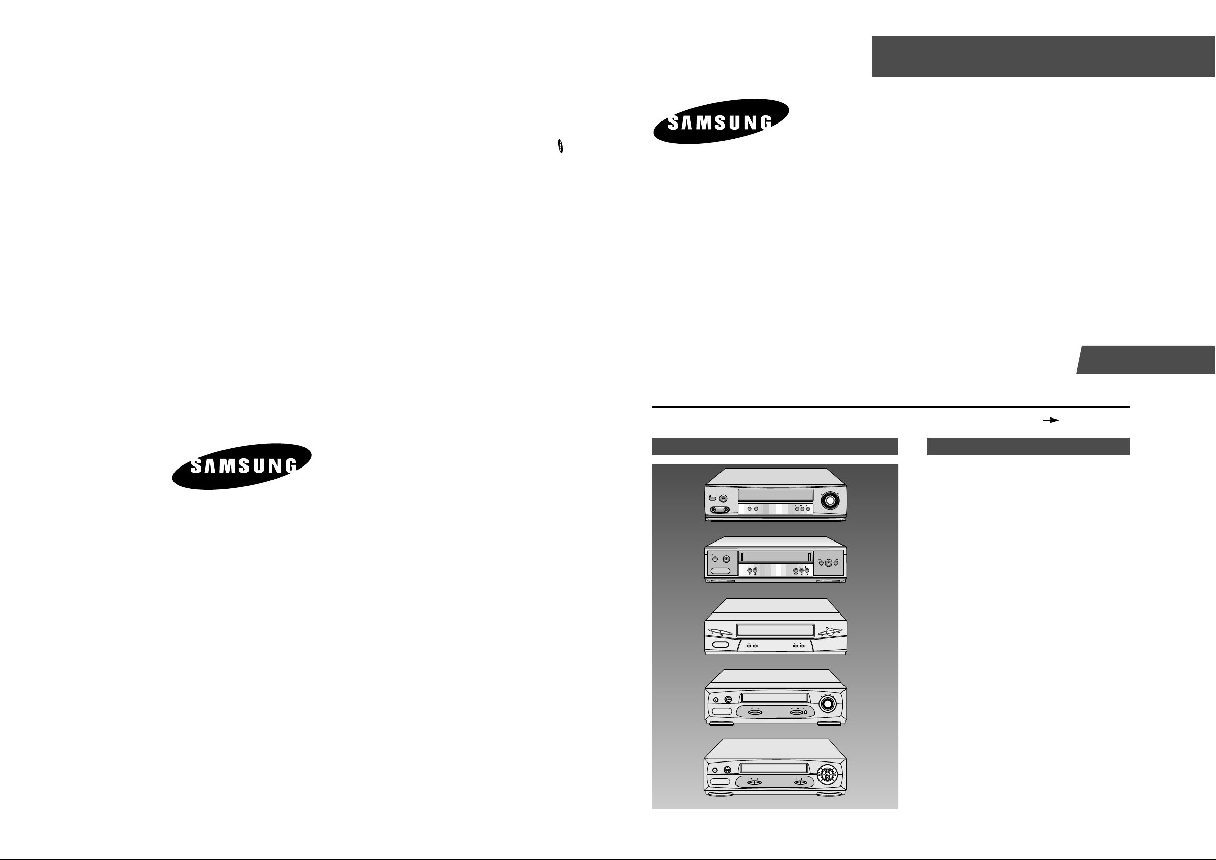
SVR-443/440
SVR-243/240B/240W/2401
SVR-141/140
VCP-007LR
SERVICE
1. Precautions
2. Alignment and Adjustment
3. Exploded View and Parts List
4. Electrical Parts List
5. Schematic Diagrams
Manual
VIDEO CASSETTE RECORDER CONTENTS
For mechanical disassembly and adjustment, refer to the “Mechanical Manual” (TS-10 AC68-01405A).
SERVICE MANUAL
SVR-443/440/243/240B/240W/2401/141/140/VCP-007LR
ELECTRONICS
© Samsung Electronics Co., Ltd. MAR. 2001
Printed in Korea
AC68-01530A
SVR-140
REC STOP
PROG
EJECT
STANDBY/ON
REW F.F
PLAY
SVR-440/240B/240W
SVR-443/243
EJECT
POWER
CHANNEL
REC STOP
MENU
PLAY
REW
F.F
SVR-141
SVR-2401/VCP-007LR
REC STOP PLAY
PROG
EJECT
STANDBY/ON
REW
F.F
EJECT
PROG
REC STOP
REW F.F
PLAY
STANDBY/ON
EJECT
STANDBY/ON
PROG
REC
STOP
PLAY
REW
F.F
VIDEO AUDIO
LINE IN 2

IMPORTANT SERVICE GUIDE
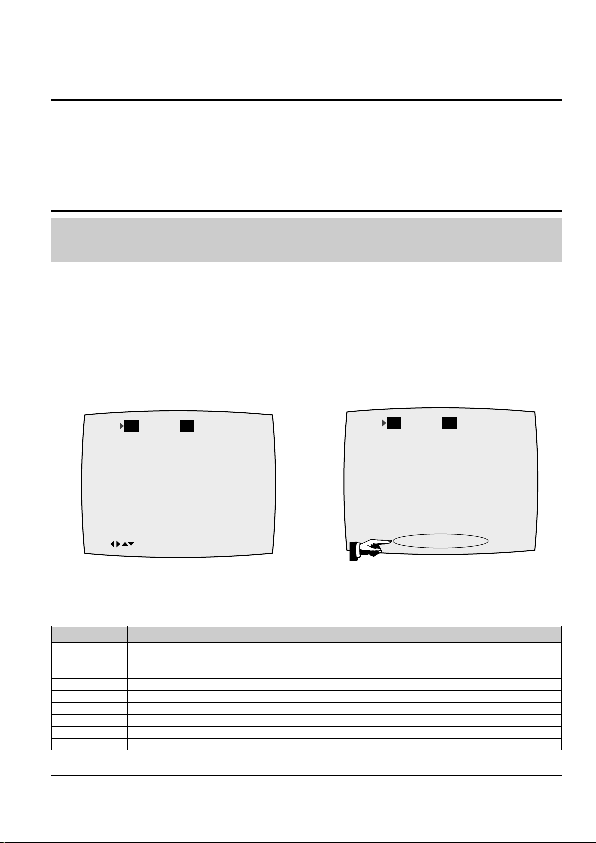
◆ MODE SWITCH (PROGRAM SWITCH) ASSEMBLY POINT
1) When installing the ass’y deck on the Main PCB, be sure to align the assembly point of mode switch.
ASSEMBLY POINT
(ALIGN TWO ARROWS)
Fig. 1
◆ HOW TO EJECT THE CASSETTE TAPE
(If the unit does not operate on condition that tape is inserted into housing ass’y)
1) Turn the Gear Worm Πclockwise in the direction of arrow with screw driver. (See Fig. 2)
(Other method ; Remove the screw of Motor Load Ass’y, Separate the Motor Load Ass’y)
2) When Slider S, T are approached in the position of unloading, rotate holder Clutch counterclockwise after inserting screw driver in the
hole of frame’s bottom in order to wind the unwiunded tape. (Refer to Fig. 3)
(If you rotate Gear Worm Πcontinuously when tape is in state of unwinding, you may cause a tape contamination by grease and
tape damage. Be sure to wind the unwiunded tape in the state of set horizontally.)
3) Rotate Gear Worm ˇ clockwise using screw driver again up to the state of eject mode and then pick out the tape. (Refer to Fig. 2)
Fig. 2 Fig. 3
ΠGEAR WORM
FRAME
Samsung Electronics 1-1
1. Precautions
1. Be sure that all of the built-in protective devices are
replaced. Restore any missing protective shields.
2. When reinstalling the chassis and its assemblies, be
sure to restore all protective devices, including :
control knobs and compartment covers.
3. Make sure that there are no cabinet openings
through which people--particularly children
--might insert fingers and contact dangerous
voltages. Such openings include the spacing
between the picture tube and the cabinet mask,
excessively wide cabinet ventilation slots, and
improperly fitted back covers.
If the measured resistance is less than 1.0 megohm
or greater than 5.2 megohms, an abnormality exists
that must be corrected before the unit is returned
to the customer.
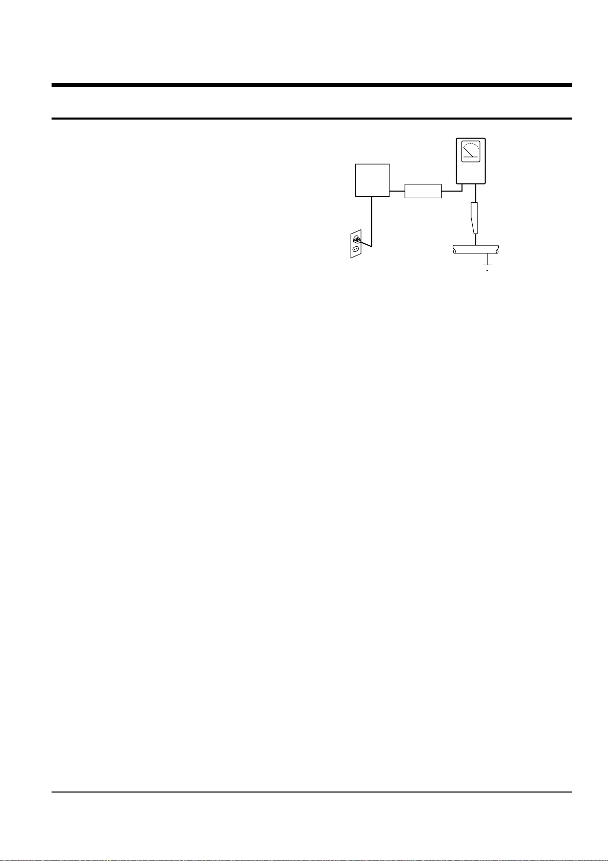
4. Leakage Current Hot Check (See Fig. 1-1) :
Warning : Do not use an isolation transformer
during this test. Use a leakage current tester or a
metering system that complies with American
National Standards Institute (ANSI C101.1,
Leakage Current for Appliances), and Underwriters
Laboratories (UL Publication UL1410, 59.7).
5. With the unit completely reassembled, plug the AC
line cord directly the power outlet. With the unit’s
AC switch first in the ON position and then OFF,
measure the current between a known earth
ground (metal water pipe, conduit, etc.) and all
exposed metal parts, including : antennas, handle
brackets, metal cabinets, screwheads and control
shafts. The current measured should not exceed
0.5 milliamp. Reverse the power-plug prongs in the
AC outlet and repeat the test.
6. X-ray Limits :
The picture tube is designed to prohibit X-ray
emissions. To ensure continued X-ray protection,
replace the picture tube only with one that is the
same type as the original.
Fig. 1-1 AC Leakage Test
7. Antenna Cold Check :
With the unit’s AC plug disconnected from the
AC source, connect an electrical jumper across the
two AC prongs. Connect one lead of the ohmmeter
to an AC prong.
Connect the other lead to the coaxial connector.
8. High Voltage Limit :
High voltage must be measured each time
servicing is done on the B+, horizontal deflection
or high voltage circuits.
Heed the high voltage limits. These include the
X-ray protection Specifications Label, and the
Product Safety and X-ray Warning Note on the
service data schematic.
9. Some semiconductor (“solid state”) devices are
easily damaged by static electricity.
Such components are called Electrostatically
Sensitive Devices (ESDs); examples include
integrated circuits and some field-effect transistors.
The following techniques will reduce the
occurrence of component damage caused by static
electricity.
10. Immediately before handling any semiconductor
components or assemblies, drain the electrostatic
charge from your body by touching a known
earth ground. Alternatively, wear a discharging
Wrist-strap device. (Be sure to remove it prior to
applying power--this is an electric shock
precaution.)
DEVICE
UNDER
TEST
(READING SHOULD
NOT BE ABOVE
0.5mA)
LEAKAGE
CURRENT
TESTER
EARTH
GROUND
TEST ALL
EXPOSED METER
SURFACES
ALSO TEST WITH
PLUG REVERSED
(USING AC ADAPTER
PLUG AS REQUIRED)
2-WIRE CORD

Precautions
1-2 Samsung Electronics
11. High voltage is maintained within specified limits
by close-tolerance, safety-related components and
adjustments. If the high voltage exceeds the
specified limits, check each of the special
components.
12. Design Alteration Warning :
Never alter or add to the mechanical or electrical
design of this unit. Example : Do not add
auxiliary audio or video connectors.
Such alterations might create a safety hazard.
Also, any design changes or additions will void
the manufacturer’s warranty.
13. Hot Chassis Warning :
Some TV receiver chassis are electrically
connected directly to one conductor of the AC
power cord. If an isolation transformer is not
used, these units may be safely serviced only if
the AC power plug is inserted so that the chassis
is connected to the ground side of the AC source.
To confirm that the AC power plug is inserted
correctly, do the following : Using an AC
voltmeter, measure the voltage between the
chassis and a known earth ground. If the reading
is greater than 1.0V, remove the AC power plug,
reverse its polarity and reinsert. Re-measure the
voltage between the chassis and ground.
14. Some TV chassis are designed to operate with 85
volts AC between chassis and ground, regardless
of the AC plug polarity. These units can be safely
serviced only if an isolation transformer inserted
between the receiver and the power source.
15. Never defeat any of the B+ voltage interlocks.
Do not apply AC power to the unit (or any of its
assemblies) unless all solid-state heat sinks are
correctly installed.
16. Always connect a test instrument’s ground lead to
the instrument chassis ground before connecting
the positive lead; always remove the instrument’s
ground lead last.
17. Observe the original lead dress, especially near
the following areas : Antenna wiring, sharp
edges, and especially the AC and high voltage
power supplies. Always inspect for pinched, outof-place, or frayed wiring. Do not change the
spacing between components and the printed
circuit board. Check the AC power cord for
damage. Make sure that leads and components
do not touch thermally hot parts.
18. Picture Tube Implosion Warning :
The picture tube in this receiver employs
“integral implosion” protection. To ensure
continued implosion protection, make sure that
the replacement picture tube is the same as the
original.
19. Do not remove, install or handle the picture tube
without first putting on shatterproof goggles
equipped with side shields. Never handle the
picture tube by its neck. Some “in-line” picture
tubes are equipped with a permanently attached
deflection yoke; do not try to remove such
“permanently attached” yokes from the picture
tube.
20. Product Safety Notice :
Some electrical and mechanical parts have special
safety-related characteristics which might not be
obvious from visual inspection. These safety
features and the protection they give might be
lost if the replacement component differs from the
original--even if the replacement is rated for
higher voltage, wattage, etc.
Components that are critical for safety are
indicated in the circuit diagram by shading,
( or ).
Use replacement components that have the same
ratings, especially for flame resistance and
dielectric strength specifications. Areplacement
part that does not have the same safety
characteristics as the original might create shock,
fire or other hazards.
Samsung Electronics
2-1
2. Alignment and Adjustment
2-1 Reference
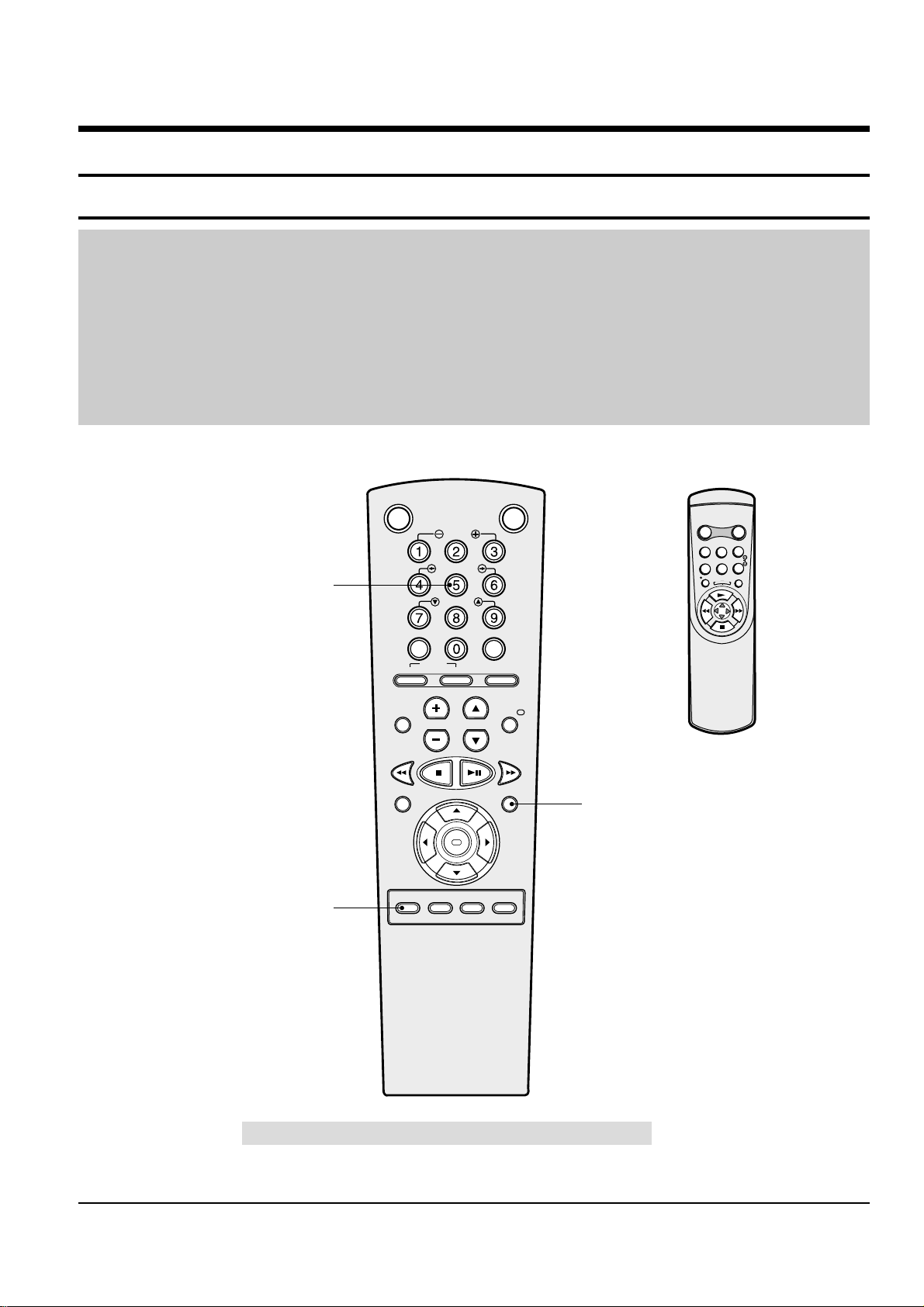
1) X-Point (Tracking center) adjustment, “Head switching adjustment” and “NVRAM option setting” can be adjusted with remote control.
2) When replacing the Micom (IC601) and NVRAM (IC605 ; EEPROM) be sure to adjust the “Head switching adjustment” and
“NVRAM option setting”.
3) When replacing the cylinder ass’y, be sure to adjust the “X-Point” and “Head switching adjustment”.
4) Among Samsung VCR remote control used for adjustment as a accessory, only the remote control that has figures buttons (0 ~ 9) is
available for all adjustment regardless of chassis.
5) How to adjustment.
- Press the “SW718” button on Main PCB to set the adjustment mode.
- If the corresponding adjustment button is pressed, the adjustment is performed automatically.
- If the adjustment is completed, be sure to turn the power off.
2-1-1 Location of adjustment button of remote control
Fig. 2-1
Remote Control for adjustment is not supplied as a Service Jig.
OK
VCR STANDBY/ON TV STANDBY/ON
SLOW
SHUTTLE
V-LOCK
CLR/RST F.ADV INDEX
TV VCR INPUT
REPEAT
VOL PROG/TRK
AUDIO
REC MENU
SPEED DUB TV/VCR TIMER
DISP./
SELECT
-/--
X-Point (Tracking Center) Adjustment
("5" Button)
Head Switching Adjustment
("SPEED" Button)
NVRAM Option Setting
("MENU" Button)
<This type of remote control can adjust.>
<This type of remote control can not adjust.>
R
E
P
E
A
T
STANDBY/ON DISPLAY
CNT.RESET SPEED
IIP/S IPC
TRK
REC MENU
2-2
Samsung Electronics
Alignment and Adjustment
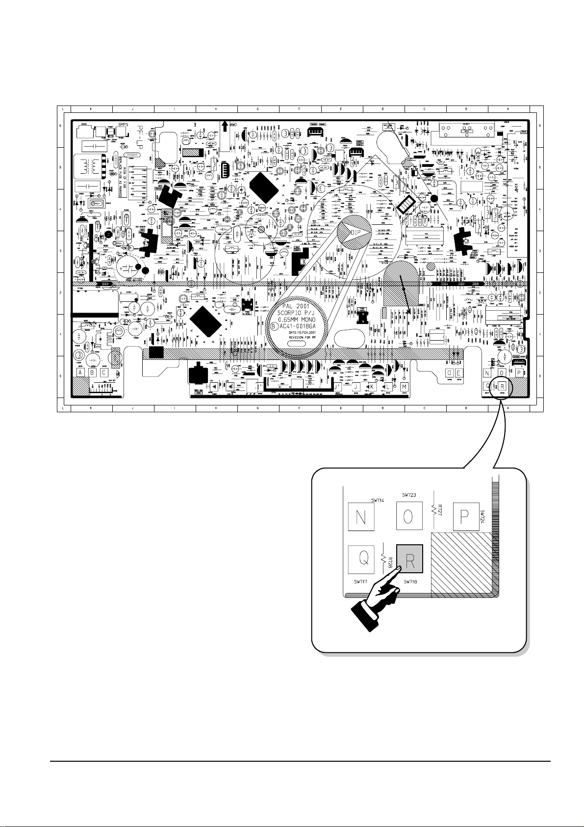
2-1-2 SW718 (TEST) location for adjustment mode setting
Fig. 2-2 Main PCB (Top View)
PRESS

Alignment and Adjustment
Samsung Electronics
2-3
2-2 Mechanical Adjustment
Note : Refer to the Mechanical Manual “TS-10 (AC68-01405A)” for the adjustment and confirmation of
ass’y full deck.
2-2-1 The number and position of test point
Test point : TP601 (Control pulse) TP301 (Envelope)
TP602 (H’D S/W -Trigger) TP302 (Audio output)
TP303 (Video output)
Fig. 2-3 Location of Test point (Main PCB-Top View)
AUDIO OUTPUT
HEAD SWITCHING
ENVELOPE
2-2-2 ACE Head Position (X-Point) Adjustment
(See the 2-2-1(d) ACE Head Position (X-Point) Adjustment
on page 2-2 of the Mechanical Manual)
1) Playback the alignment tape (Color bar).
2) Press the “SW718” button on Main PCB to set the
adjustment mode. (See Fig. 2-2)
3) Press the “5” button of remote control then
adjustment is operated automatically. (See Fig. 2-1)
4) Connect the CH-1 probe to TP301 (Envelope) the
CH-2 probe to TP602 (H’D switching pulse) and
then trigger to CH-1.
5) Insert the (-) driver into the X-Point adjustment
hole and adjust it so that envelope waveform is
maximum.
6) Turn the Power off.
2-4
Samsung Electronics
Alignment and Adjustment
2-3 Head Switching Point Adjustment
1) Playback the alignment tape.
2) Press the “SW718” button on Main PCB to set the adjustment mode. (See Fig. 2-2)
3) Press the “SPEED” button of remote control then adjustment is operated automatically. (See Fig. 2-1)
4) Turn the Power off.
2-4 NVRAM Option Setting
1) Press the “SW718” button on Main PCB to set the adjustment mode. (See Fig. 2-2)
2) Press the “MENU” button on the remote control about 5 seconds then option setting display is appeared.
(See Fig. 2-4)
3) Select the option number (See Table 2-1) of corresponding model with “CURSOR” button on the
remote control.
4) If selecting the option number is completed, press the “OK” button of remote control.
(If “OK” button is pressed, the selected number is changes reversed color. ; See Fig. 2-4)
5) Press the “MENU” button of remote control again to store the option number.
(“PLEASE WAIT” is displayed for a second as shown Fig. 2-5 and this setting is completed.)
6) Turn the Power off.
1) NVRAM Option is adjusted at production line basically.
2) In case Micom (IC601) and NVRAM (IC605 ; EEPROM) is replaced, be sure to set the corresponding option number of the repaired
model. (If the option is not set, the unit is not operated.)
01 02 03 04 05 06 07 08
09 10 11 12 13 14 15 16
17 18 19 20 21 22 23 24
25 26 27 28 29 30 31 32
33 34 35 36 37 38 39 40
41 42 43 44 45 46 47 48
49 50 51 52 53 54 55 56
57 58 59 60 61 62 63 64
65 66 67 68 69 70 71 72
CNG : OK SAVE : MENU
Fig. 2-4
01 02 03 04 05 06 07 08
09 10 11 12 13 14 15 16
17 18 19 20 21 22 23 24
25 26 27 28 29 30 31 32
33 34 35 36 37 38 39 40
41 42 43 44 45 46 47 48
49 50 51 52 53 54 55 56
57 58 59 60 61 62 63 64
65 66 67 68 69 70 71 72
PLEASE WAIT
Fig. 2-5
<Table 2-1 NVRAM Option Number>
MODELS OPTION NUMBER
SVR-443 9, 10, 15, 20, 24, 30, 32, 34, 36, 38, 42, 44, 47, 54, 57, 60, 61, 63
SVR-440 9, 10, 20, 30, 32, 34, 36, 38, 42, 44, 47, 52, 54, 57, 60, 61, 63
SVR-243 10, 15, 20, 24, 30, 32, 34, 36, 37, 42, 44, 47, 54, 57, 60, 61, 63, 71
SVR-240B 10, 20, 30, 32, 34, 36, 37, 42, 44, 47, 52, 54, 57, 60, 61, 63, 71
SVR-240W 10, 20, 30, 32, 34, 36, 37, 42, 44, 47, 52, 54, 57, 60, 61, 63, 71
SVR-2401 10, 20, 30, 34, 36, 37, 42, 44, 47, 52, 54, 57, 60, 61, 63, 71
SVR-141 10, 20, 24, 35, 37, 42, 44, 51, 54, 57, 60, 61, 63, 71
SVR-140 10, 20, 24, 35, 37, 42, 44, 51, 52, 54, 57, 60, 61, 63, 71
VCP-007LR 10, 20, 22, 35, 37, 42, 44, 51, 57, 60, 61, 71

Samsung Electronics 3-1
3. Exploded View and Parts List
3-1 Cabinet Assembly - - - - - - - - - - - - - - - - - - - - - - - - - - - - - - - - - - - - - - - - -
3-2 Mechanical Parts (Top Side) - - - - - - - - - - - - - - - - - - - - - - - - - - - - - - - - -
3-3 Mechanical Parts (Bottom Side) - - - - - - - - - - - - - - - - - - - - - - - - - - - - - - -
Page
3-2
3-4
3-6
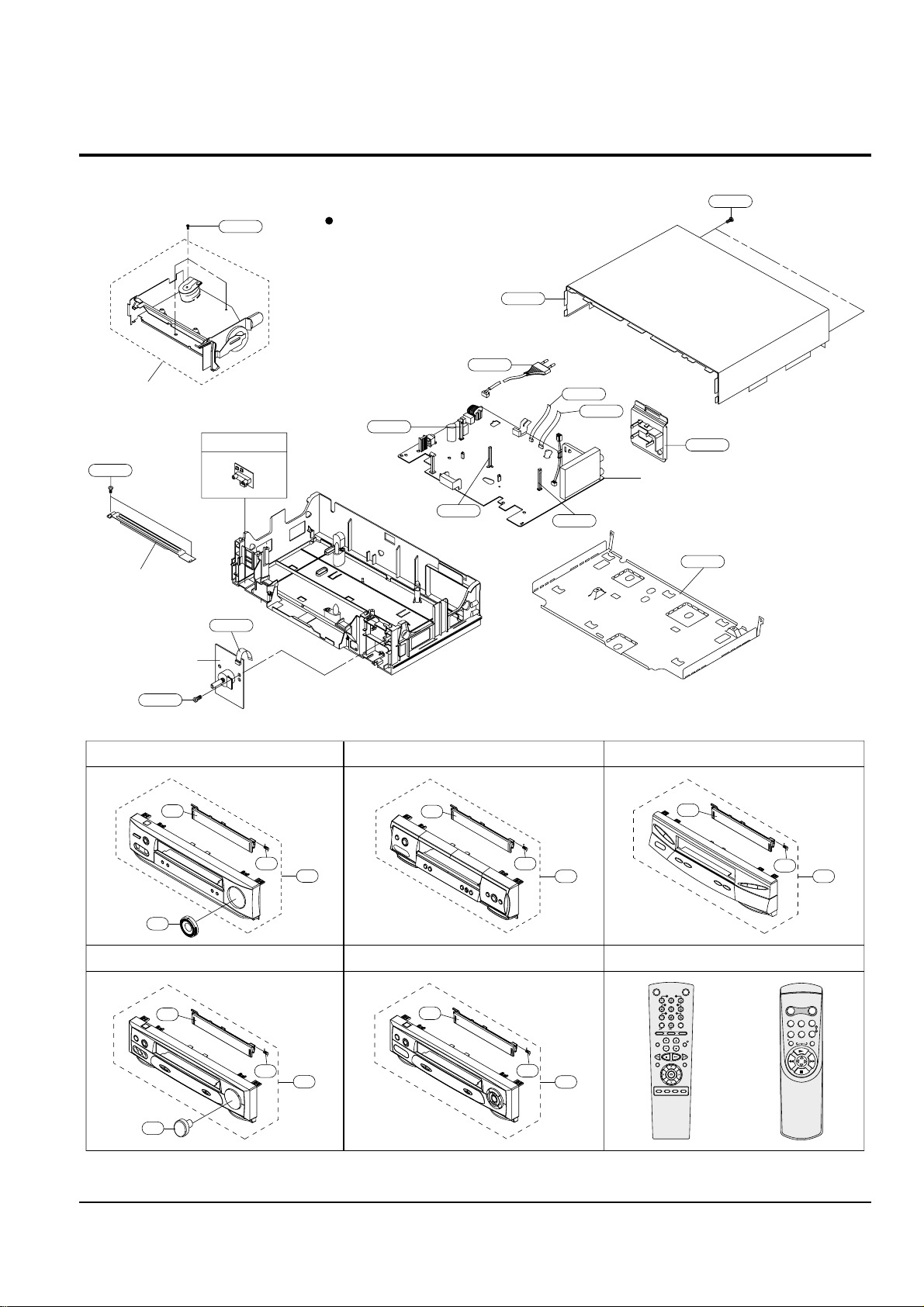
Exploded View and Parts List
3-2 Samsung Electronics
3-1 Cabinet Assembly
TM401B
102
S.N.A : Service Not Available
FULL DECK (S.N.A)
153
BRACKET-FRAME
(S.N.A)
157
157
155
101
200
MAIN PCB (S.N.A.)
CN602S
CN3A1S
S602A
S601A
LD601A
CN703S
UT01
OK
VCR STANDBY/ON TV STANDBY/ON
SLOW
SHUTTLE
V-LOCK
CLR/RST F.ADV INDEX
TV VCR INPUT
REPEAT
VOL PROG/TRK
AUDIO
REC MENU
SPEED DUB TV/VCR TIMER
DISP./
SELECT
-/--
21
21
21
55
21
1
1
1
1 1
22
22
22
22
SVR-443/243
SVR-141 SVR-140
SVR-440/240B/240W SVR-2401/VCP-007LR
F-A/V PCB (S.N.A.)
21
22
R
E
P
E
A
T
STANDBY/ON DISPLAY
CNT.RESET SPEED
IIP/S IPC
TRK
REC MENU
55
SHUTTLE PCB (S.N.A.)

Exploded View and Parts List
Samsung Electronics 3-3
Loc. No Parts No. Description ; Specification Remark
1
Refer to table below
ASSY-PANEL FRONT
21
Refer to table below
DOOR-CASSETTE
22 AC61-62032A SPRING-MASK;X-9,-,SUS,-,4.4,-,SV-C130
55 AC64-00587A KNOB-SHUTTLE;SVR-643,ABS,-,SILVER,-,-,-, SVR-443/243 ONLY
AC64-00319A KNOB-SHUTTLE;-,ABS,-,GRAY,HB,SV-130G,- SVR-141 ONLY
101
Refer to table below
CABINET TOP
102 AC63-00015A COVER-BOTTOM;-,SECC,-,T;0.5,SECC T0.5,-,
153 AC60-12126A SCREW-BH;-,BH,-,4*12,FE,FZY,-,-,155 AC60-12134A SCREW-TAP BH;-,BH,-,2-4X16,-,FE
157 AC60-10063A SCREW-TAPTITE;BH,+,-,M3,L12,ZPC3,SWRCH18
200 AC39-10019A POWER CORD;KKP-419C,H03VVH2-F,VDE/KEMA-K
CN3A1S 3809-001206 CABLE-FLAT;30V,-20to+80C,140mm,6P,1.25mm
CN602S 3809-001111 CABLE-FLAT;30V,80C,130mm,7P,1.25mm,UL289
CN703S 3809-001112 CABLE-FLAT;30V,80C,130mm,5P,1.25mm,UL289 SVR-443/243/141 ONLY
LD601A AC61-21009A HOLDER-LED;-,POM(M90-44),-,BLK,-,X-9
S601A AC61-21008A HOLDER-SENSOR;-,POM(M90-44),-,BLK,-,X-9
S602A AC61-21008A HOLDER-SENSOR;-,POM(M90-44),-,BLK,-,X-9
UT01
Refer to table below
REMOCON-ASSY
MODELS 1 21 101 UT01
SVR-443 AC97-01363B AC64-00572Q AC64-00400A AC59-00048A
SVR-440 AC97-01366B AC64-00536B AC64-00400B AC59-00048A
SVR-243 AC97-01363C AC64-00572S AC64-00400A AC59-00048A
SVR-240B AC97-01366C AC64-00536C AC64-00400B AC59-00048A
SVR-240W AC97-01366D AC64-00536D AC64-00400L AC59-00048C
SVR-2401 AC97-01313A AC64-00687A AC64-00400B AC59-00049A
SVR-141 AC97-00873B AC64-00683U AC64-00400B AC59-00013C
SVR-140 AC97-00873C AC64-00683T AC64-00400A AC59-00013C
VCP-007LR AC97-01466A AC64-00687B AC64-00400B AC59-00013C
Exploded View and Parts List
3-4 Samsung Electronics
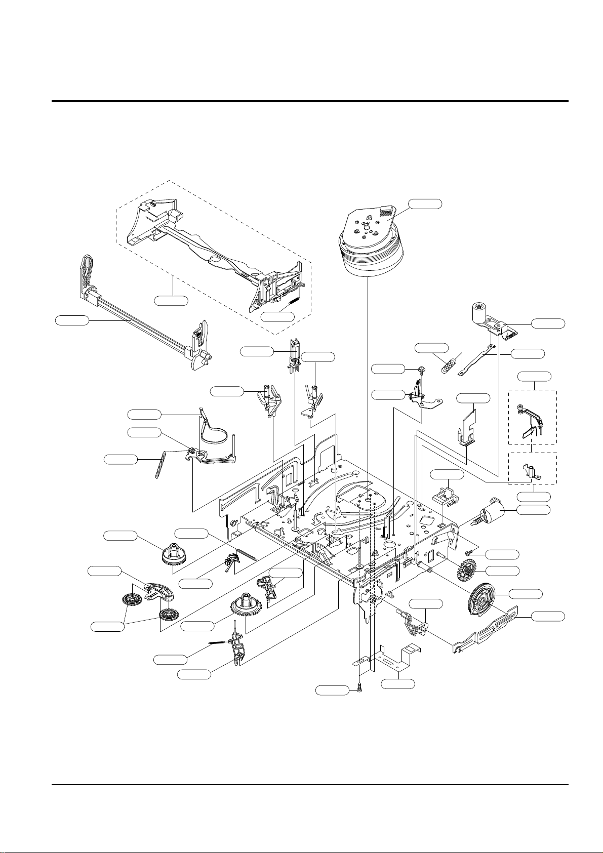
3-2 Mechanical Parts (Top Side)
G001
G555
G510
G480
K546
G680
G681
B410
B575
B440
B448
B452
G546
G060
G520
G527
K188
K182
K110
K240
K248
K350
K330
K140
K340
G070
K470
B474
B473
K250
K530
K490
G530
G420
G450
K502
(OPTIONAL)
(OPTIONAL)

Exploded View and Parts List
Samsung Electronics 3-5
Loc. No Parts No. Description ; Specification Remark
B410 AC31-00012A MOTOR-LOADING ASSY;-,TS-10,-,-,-,-,-,-,B440 AC60-10515A SCREW-MACHINE;-,PH,+,-,M3,L3,ZPC,-,YEL
B448 AC66-00008A GEAR-WORM WHEEL;TS-10,POM,0.8,40,-,NAT,3
B452 AC66-00011A GEAR-FL CAM;TS-10,POM,0.8,59,-,BLK,48.48
B473 AC61-00105A SPRING-PINCH DRIVE;TS-10,SUS304-WPB,-,-,
B474 AC61-30180A PLATE-JOINT;-,SECC20/20,T0.8,-,X-9
B575 AC47-00002A DAMPER-CAPSTAN;TS-10,POM,-,-,BLACK
G001 AC97-01212A ASSY-CYLINDER;PALCTS10,4HD/DLC 4HEAD
AC97-01208A ASSY-CYLINDER;P AL,CTS10,2HD(LP)/DLC 2HEAD
AC97-01209A ASSY-CYLINDER;P AL,CTS10,2HD(LP) VCP
G060 6006-001092 SCREW-ASS’Y MACH;WS,PH,+,M3.0,L6.0,ZPC(Y
G070 AC61-00161A PLATE-GROUND DECK;TS-10,SPTE,T0.3,G420 AC66-80142A SLIDER-SUPPLY ASSY;-,X-9(TS),-,-,-,X-9
G450 AC66-80141A SLIDER-TAKE UP ASSY;-,X-9(TS),-,-,-,X-9
G480 AC33-00009A HEAD-ACE ASS’Y;-,PPS,TS-10,-,G510 6006-001075 SCREW-ASS’Y TAPT;WSP,PH,+,M2.6,L5.0,ZPC(
G520 AC66-00033A LEVER-#9 GUIDE ASS’Y;TS-10,-,-,-,-,-,-,G527 AC61-60553A SPRING-#9 GUIDE;-,ES,SUS304-WPB,OD3.1,0.
G530 AC33-00007A HEAD-FE;-,-,HVFHPOO43A,-,G546 AC66-00005A LEVER-FL DOOR;TS-10,POM,-,-,-,-,NAT,G555 AC66-00032A LEVER-UNIT PINCH ASS’Y;TS-10,-,-,-,-,-,G680 AC66-00046A LEVER-HEAD CLEANER ASS’Y;TS-10,POM+URETH (OPTIONAL)
G681 AC61-50686A SLEEVE-HEAD CLEANER;-,POM,-,-,-,-,-,-,TS (OPTIONAL)
K110 AC66-10267A REEL-DISK S;X-9,POM,-,-,-,-,-,K140 AC66-10268A REEL-DISK T;X-9,POM,-,-,-,-,-,K182 AC66-30524A LEVER-IDLER;-,POM,-,-,-,-,-,K188 AC66-00039A GEAR-IDLE;TS-10,PET K3372,0.5,-,-,NTR,28
K240 AC66-00035A LEVER-TENSION ASS’Y;TS-10,SECC E20/20+SU
K248 AC61-00107A SPRING-TENSION LEVER;TS-10,SUS304-WPB,-,
K250 AC69-00104A BAND-BRAKE ASS’Y;TS-10,-,-,-,-,-,K330 AC66-30550A LEVER-S.BRAKE ASSY;-,POM+SUS,-,-,-,X-9
K340 AC66-30549A LEVER-T.BRAKE ASSY;-,POM+SUS,-,-,-,X-9
K350 AC61-00106A SPRING-BRAKE;TS-10,SUS304-WPB,-,-,-,-,-,
K470 AC66-00020A SLIDER-FL DRIVE;TS-10,SECC E20/20,1.0,-,
K490 AC61-00120A HOLDER-FL CASS. ASS’Y;TS-10,-,-,-,-,K502 AC61-60561A SPRING-FL.LEVER-LR;-,ES,SUS304 WPB,PI2.7
K530 AC66-00034A LEVER-FL ARM ASS’Y;TS-10,-,-,-,-,-,-,K546 AC61-50658A GUIDE-CASS. DOOR;X-9,POM,-,NTR,-,-
Exploded View and Parts List
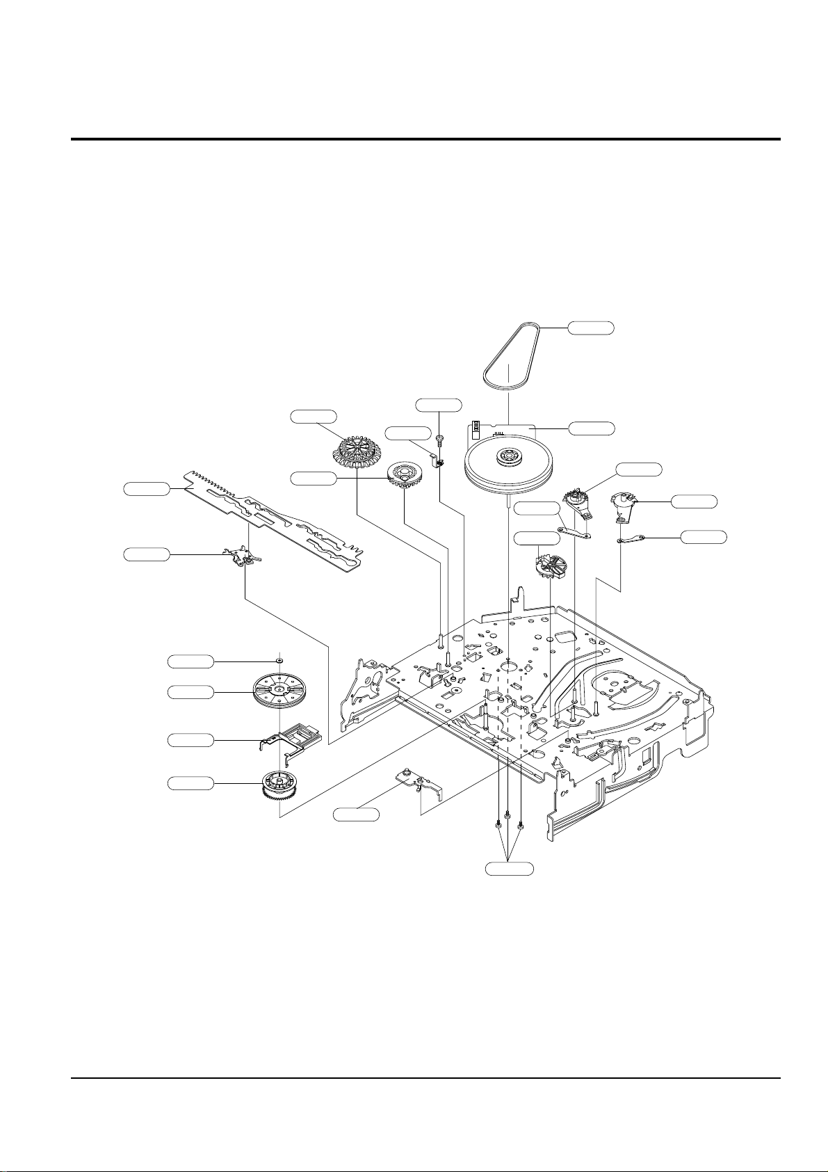
3-6 Samsung Electronics
3-3 Mechanical Parts (Bottom Side)
G542
B462
B560
B501
B484
B488
B500
B456
B458
B464
B468
K222
K200
K225
K221
B478
B570
B460
B489

Exploded View and Parts List
Samsung Electronics 3-7
Loc. No Parts No. Description ; Specification Remark
B456 AC66-00009A GEAR-JOINT 1;TS-10,POM,1.5,17.5(22),-,NA
B458 AC66-00012A GEAR-JOINT 2;TS-10,POM,1.0,23,-,BLK,24.6
B460 AC61-00090A BRACKET-GEAR;TS-10,0.8,-,B462 AC60-10517A SCREW-TAP TITE;-,PH,+,-,M2.6,L5,ZPC,-,YE
B464 AC66-00019A SLIDER-CAM;TS-10,SECC E20/20,1.2,-,-,-,B468 AC66-00017A LEVER-PINCH DRIVE;TS-10,SECC E20/20,1.0
B478 AC66-00016A LEVER-TENSION DRIVE;TS-10,SECC E20/20,1
B484 AC66-00030A GEAR-LOADING DR. ASS’Y;TS-10,POM+SWPB,-,
B488 AC66-00023A LEVER-S LOADING;TS-10,POM,-,-,-,-,NAT,B489 AC66-00021A LINK-LOADING S;TS-10,SECC E20/20,0.8,-,B500 AC66-00024A LEVER-T LOADING;TS-10,POM,-,-,-,-,NAT,B501 AC66-00022A LINK-LOADING T;TS-10,SECC E20/20,0.8,-,B560 AC31-00010A MOTOR-CAPSTAN;-,SANKYO,-,B570 AC60-10514A SCREW-CAPSTAN;-,PH,+,M2.6,L6,G542 AC66-60051A BELT-PULLEY;-,5CM-70,2 * 2,-,71.3,-,X-9
K200 AC61-21012A HOLDER-CLUTCH ASSY;-,-,-,-,-,X-9
K221 AC66-20581A GEAR-CENTER ASSY;-,POM,M=O.5,-,HIGHT T.,
K222 AC60-30306A WASHER-SLIT;-,-,ID2.1,OD5.0,T0.5,-,POLYS
K225 AC66-00006A LEVER-UP DOWN;TS-10,POM,-,-,-,-,NAT,-

Exploded View and Parts List
3-8 Samsung Electronics
MEMO

Loc.No Part No Description ; Specification Remark Loc.No Part No Description ; Specification Remark
Samsung Electronics
4-1
- - ASSY PCB-MAIN-FULL S.N.A.
S.M.P.S. PARTS
BD1SD1 AC27-92001M INDUCTOR;70UH-M RT BFS3565R2F,-,-,-,BD1SF1 3301-000297 CORE-FERRITE BEAD;AA,3.6x1.2x5.7mm,1400, Not used SVR-2401
BD1SF3 AC27-92001M INDUCTOR;70UH-M RT BFS3565R2F,-,-,-,- Not used SVR-2401
BD1SR1 3301-000297 CORE-FERRITE BEAD;AA,3.6x1.2x5.7mm,1400, SVR-2401 ONLY
BD1SS2 AC27-92001M INDUCTOR;70UH-M RT BFS3565R2F,-,-,-,BD1SS3 3301-000297 CORE-FERRITE BEAD;AA,3.6x1.2x5.7mm,1400,
C1SD03 2201-000812 C-CERAMIC,DISC;2.2nF,20%,400V,Y5U,BK,12.
C1SD04 2201-000812 C-CERAMIC,DISC;2.2nF,20%,400V,Y5U,BK,12.
C1SD11 2401-001682 C-AL;82uF,20%,400V,GP,BK,22x25,10
C1SD11 2401-003302 C-AL;47uF,20%,400V,GP,TP,18X31.5,7. SVR-2401 ONLY
C1SD12 2305-001029 C-FILM,MPEF;10nF,10%,630V,TP,12x9x12.5,5
C1SD13 2201-000376 C-CERAMIC,DISC;0.22nF,5%,50V,SL,TP,6.3x3
C1SD13 2301-000361 C-FILM,PEF;1.2nF,10%,50V,TP,-,5mm SVR-2401 ONLY
C1SF12 2401-001200 C-AL;33uF,20%,50V,WT,TP,6.3x11,5 Not used SVR-2401
C1SR12 2401-000905 C-AL;22uF,20%,16V,BP,-,6x11,2.5mm SVR-2401 ONLY
C1SR14 2301-000445 C-FILM,PEF;4.7nF,5%,50V,TP,5.5x7x3mm,5mm SVR-2401 ONLY
C1SS01 2305-001021 C-FILM,MPEF;100nF,20%,275V,TP,17.5x7x13.
C1SS02 2305-001021 C-FILM,MPEF;100nF,20%,275V,TP,17.5x7x13.
C1SS03 2301-000361 C-FILM,PEF;1.2nF,10%,50V,TP,-,5mm
C1SS12 2201-000129 C-CERAMIC,DISC;0.1nF,10%,1kV,Y5P,TP,7x4, Not used SVR-2401
C1SS31 2401-000385 C-AL;10uF,20%,100V,GP,TP,6.3x11,5
C1SS32 2401-003137 C-AL;330UF,20%,50V,WT,TP,10X16MM,5
C1SS33 2401-001126 C-AL;330uF,20%,25V,WT,TP,10x12.5,5
C1SS34 2401-003477 C-AL;330UF,20%,25V,LZ,TP,10X12.5MM,
C1SS35 2401-003480 C-AL;1000UF,20%,10V,LZ,TP,10X16MM,5
C1SS36 2401-001479 C-AL;470uF,20%,10V,GP,TP,-,C1SS39 2301-000129 C-FILM,PEF;100nF,5%,50V,TP,10X9X4.3X5,5m
CN1SS1 3711-000178 CONNECTOR-HEADER;1WALL,2P,1R,3.96mm,STRA
D1SD11 0402-001195 DIODE-RECTIFIER;F1T4,400V,1.0A,TS-1,TP
D1SD31 0402-001195 DIODE-RECTIFIER;F1T4,400V,1.0A,TS-1,TP
D1SF05 0402-001196 DIODE-RECTIFIER;1T5,600V,1A,TS-1,TP Not used SVR-2401
D1SF12 0402-001195 DIODE-RECTIFIER;F1T4,400V,1.0A,TS-1,TP Not used SVR-2401
D1SR11 0401-000101 DIODE-SWITCHING;1N4148,100V,200mA,DO-35, SVR-2401 ONLY
D1SS01 0402-001196 DIODE-RECTIFIER;1T5,600V,1A,TS-1,TP
D1SS02 0402-001196 DIODE-RECTIFIER;1T5,600V,1A,TS-1,TP
D1SS03 0402-001196 DIODE-RECTIFIER;1T5,600V,1A,TS-1,TP
D1SS04 0402-001196 DIODE-RECTIFIER;1T5,600V,1A,TS-1,TP
D1SS11 0402-000012 DIODE-RECTIFIER;UF4007,1KV,1A,DO-41,TP
D1SS30 0402-000127 DIODE-RECTIFIER;1N4002,100V,1A,DO-41,TP
D1SS31 0402-001195 DIODE-RECTIFIER;F1T4,400V,1.0A,TS-1,TP
D1SS32 0402-001194 DIODE-RECTIFIER;UG2D,200V,2A,DO-204AC,TP
D1SS33 0402-000431 DIODE-RECTIFIER;FML-M02S,200V,2.5A,TO-22
F1SS01 3601-001123 FUSE-CARTRIDGE;250V,1.6A,TIME-LAG,CERAMI
IC1SF1 1203-001802 IC-PWM CONTROLLER;STR-G6551,TO-220F,5P,- Not used SVR-2401
IC1SS1 0604-001028 PHOTO-COUPLER;TR,50-600%,250mW,DIP-4,ST
IC1SS2 AC14-12006D IC;KA431Z,TO-92,TAPING
L1SS02 AC29-00002A FILTER LINE NOISE;-,30mH,-,-,BLF-2116
L1SS31 AC27-12001N COIL-CHOKE;10UH-15%,RA,K-30,Q80,150KHZ,L1SS32 AC27-12001N COIL-CHOKE;10UH-15%,RA,K-30,Q80,150KHZ,PT1SS1 AC26-00002C TRANS SWITCHING;-,-,EE2621,-,UL/CSA/DEMK
PT1SS1 AC26-00002G TRANS SWITCHING;EE2621,SV-643F,-,230V,FE SVR-2401 ONLY
Q1SR01 0502-001050 TR-POWER;2SC4517A,NPN,30W,TO-220,ST,10- SVR-2401 ONLY
Q1SR02 0501-000442 TR-SMALL SIGNAL;KTC3203-Y,NPN,400MW,T0-9 SVR-2401 ONLY
R1SD11 2001-000305 R-CARBON;110KOHM,5%,1/8W,AA,TP,1.8X3.2MM SVR-2401 ONLY
R1SD12 2001-000325 R-CARBON;120OHM,5%,1/8W,AA,TP,1.8X3.2MM
R1SD12 2001-000003 R-CARBON;330ohm,5%,1/8W,AA,TP,1.8x3.2mm SVR-2401 ONLY
R1SD13 2001-000076 R-CARBON;47KOHM,5%,1/4W,AA,TP,2.4X6.4MM
R1SD13 2001-000305 R-CARBON;110KOHM,5%,1/8W,AA,TP,1.8X3.2MM SVR-2401 ONLY
R1SD14 2001-000076 R-CARBON;47KOHM,5%,1/4W,AA,TP,2.4X6.4MM
R1SD14 2001-000305 R-CARBON;110KOHM,5%,1/8W,AA,TP,1.8X3.2MM SVR-2401 ONLY
R1SD15 2001-000076 R-CARBON;47KOHM,5%,1/4W,AA,TP,2.4X6.4MM
R1SD15 2001-000305 R-CARBON;110KOHM,5%,1/8W,AA,TP,1.8X3.2MM SVR-2401 ONLY
R1SD16 2003-000994 R-METAL OXIDE(S);33Kohm,5%,2W,AF,TP,3.9x
R1SD31 2001-000780 R-CARBON;470OHM,5%,1/8W,AA,TP,1.8X3.2MM
R1SD31 2001-000515 R-CARBON;220OHM,5%,1/8W,AA,TP,1.8X3.2MM SVR-2401 ONLY
R1SD32 2001-000429 R-CARBON;1KOHM,5%,1/8W,AA,TP,1.8X3.2MM
R1SD32 2001-000221 R-CARBON;1.2KOHM,5%,1/8W,AA,TP,1.8X3.2M SVR-2401 ONLY
R1SF11 2001-000076 R-CARBON;47KOHM,5%,1/4W,AA,TP,2.4X6.4MM Not used SVR-2401
R1SF15 2001-000591 R-CARBON;3.3KOHM,5%,1/8W,AA,TP,1.8X3.2M Not used SVR-2401
R1SF19 2001-000904 R-CARBON;620OHM,5%,1/8W,AA,TP,1.8X3.2MM Not used SVR-2401
R1SF20 2003-002197 R-METAL OXIDE;0.47ohm,5%,2W,AF,TP,3.9x10 Not used SVR-2401
R1SF21 2001-000096 R-CARBON(S);1MOHM,5%,1/2W,AA,TP,2.4X6.4M Not used SVR-2401
R1SR11 2003-000119 R-METAL OXIDE;0.68ohm,5%,2W,AE,TP,6x16mm SVR-2401 ONLY
R1SR12 2003-000264 R-METAL OXIDE;300ohm,5%,1W,AD,TP,4.3x12m SVR-2401 ONLY
R1SR14 2001-000003 R-CARBON;330ohm,5%,1/8W,AA,TP,1.8x3.2mm SVR-2401 ONLY
R1SS10 2006-000262 R-CEMENT;2.7ohm,10%,2W,CB,TP,7.5x11x20.
R1SS11 2003-000994 R-METAL OXIDE(S);33Kohm,5%,2W,AF,TP,3.9x
R1SS13 2003-000148 R-METAL OXIDE;100OHM,5%,2W,AE,TP,6X16MM Not used SVR-2401
R1SS32 2001-000429 R-CARBON;1KOHM,5%,1/8W,AA,TP,1.8X3.2MM
R1SS33 2004-000869 R-METAL;3Kohm,1%,1/8W,AA,TP,1.8x3.2mm
R1SS34 2004-000459 R-METAL;2.2Kohm,1%,1/8W,AA,TP,1.8x3.2m
VA1SS1 1405-001026 VARISTOR;470V,600A,9x7mm,TP
ZD1SS1 0403-000571 DIODE-ZENER;UZP43B,43V,40-46V,1W,DO-41,T SVR-2401 ONLY
POWER DRIVE PARTS
C1P102 2401-001545 C-AL;47uF,20%,25V,GP,TP,6.3x7mm,2.5
C1P103 2401-000598 C-AL;1uF,20%,50V,GP,TP,4x7,5
C1P104 2401-002299 C-AL;4.7uF,20%,50V,GP,TP,5x7,5
C1P105 2401-003107 C-AL;47uF,20%,16V,GP,TP,5x7,5
C1P106 2401-003107 C-AL;47uF,20%,16V,GP,TP,5x7,5
C1P108 2401-001573 C-AL;47uF,20%,50V,GP,TP,6.3x11,2.5
D1P101 0401-000101 DIODE-SWITCHING;1N4148,100V,200mA,DO-35,
Q1P101 0501-000616 TR-SMALL SIGNAL;KSC2328A-Y,NPN,1W,TO-92L
Q1P102 0501-000616 TR-SMALL SIGNAL;KSC2328A-Y,NPN,1W,TO-92L
Q1P104 0501-002268 TR-SMALL SIGNAL;STB1277,PNP,625mW,TO-92,
Q1P105 0504-000116 TR-DIGITAL;KSR1001,NPN,300MW,4.7K/4.7K,T
R1P101 2001-000855 R-CARBON;560OHM,5%,1/4W,AA,TP,2.4X6.4MM
R1P101 2001-000034 R-CARBON;220OHM,5%,1/4W,AA,TP,2.4X6.4MM VCP ONLY
R1P106 2001-000449 R-CARBON;2.2KOHM,5%,1/8W,AA,TP,1.8X3.2M
R1P107 2001-000273 R-CARBON;100KOHM,5%,1/8W,AA,TP,1.8X3.2M
R1P108 2001-000611 R-CARBON;3.9KOHM,5%,1/4W,AA,TP,2.4X6.4M
R1P115 2001-000554 R-CARBON;270OHM,5%,1/8W,AA,TP,1.8X3.2MM
R1P116 2001-000563 R-CARBON;27KOHM,5%,1/8W,AA,TP,1.8X3.2MM VCP ONLY
ZD1P02 0403-000717 DIODE-ZENER;MTZJ5.1B,5.1V,4.94-5.2V,500m
ZD1P04 0403-000720 DIODE-ZENER;MTZJ9.1B,9.1V,8.57-9.01V,500
SYSTEM CONTROL/SERVO PARTS
C601 2401-003107 C-AL;47uF,20%,16V,GP,TP,5x7,5
C602C 2203-000609 C-CERAMIC,CHIP;22nF,10%,50V,X7R,TP,2012
C603C 2203-000891 C-CERAMIC,CHIP;4.7nF,10%,50V,X7R,TP,2012
C604C 2203-000891 C-CERAMIC,CHIP;4.7nF,10%,50V,X7R,TP,2012
C605C 2203-000260 C-CERAMIC,CHIP;10nF,10%,50V,X7R,TP,2012
C606C 2203-000260 C-CERAMIC,CHIP;10nF,10%,50V,X7R,TP,2012
C607 2401-000118 C-AL;1000uF,20%,10V,GP,TP,10x12.5,5
C608C 2203-000575 C-CERAMIC,CHIP;220NF,10%,25V,X7R,TP,2012
C609C 2203-000609 C-CERAMIC,CHIP;22nF,10%,50V,X7R,TP,2012
C611C 2203-001579 C-CERAMIC,CHIP;15nF,10%,50V,NP0,TP,2012
C612 2202-002037 C-CERAMIC,MLC-AXIAL;100nF,80-20%,50V,Y5V
C613C 2203-000609 C-CERAMIC,CHIP;22nF,10%,50V,X7R,TP,2012
C615C 2203-000444 C-CERAMIC,CHIP;1nF,10%,50V,X7R,TP,2012,C616 2202-000807 C-CERAMIC,MLC-AXIAL;22nF,+80-20%,25V,Y5V
4. Electrical Parts List

Loc.No Part No Description ; Specification RemarkLoc.No Part No Description ; Specification Remark
4-2
Samsung Electronics
Electrical Parts List
C617 2401-000591 C-AL;1uF,20%,50V,BP,TP,3x5,2.5mm
C618 2401-000360 C-AL;100uF,20%,50V,GP,TP,8x11.5,5
C619C 2203-000260 C-CERAMIC,CHIP;10nF,10%,50V,X7R,TP,2012
C620C 2203-000192 C-CERAMIC,CHIP;100nF,+80-20%,50V,Y5V,TP,
C621 2401-000118 C-AL;1000uF,20%,10V,GP,TP,10x12.5,5
C622C 2203-001680 C-CERAMIC,CHIP;68nF,20%,50V,Z5U,TP,2012
C623C 2203-000609 C-CERAMIC,CHIP;22nF,10%,50V,X7R,TP,2012
C624 2202-000205 C-CERAMIC,MLC-AXIAL;22pF,5%,50V,SL,TP,1. Not used VCP
C625 2202-000205 C-CERAMIC,MLC-AXIAL;22pF,5%,50V,SL,TP,1. Not used VCP
C626C 2203-000634 C-CERAMIC,CHIP;0.022nF,5%,50V,NP0,TP,201
C627C 2203-000634 C-CERAMIC,CHIP;0.022nF,5%,50V,NP0,TP,201
C629C 2203-000444 C-CERAMIC,CHIP;1nF,10%,50V,X7R,TP,2012,C633C 2203-000260 C-CERAMIC,CHIP;10nF,10%,50V,X7R,TP,2012
C634C 2203-000260 C-CERAMIC,CHIP;10nF,10%,50V,X7R,TP,2012
C635C 2203-000495 C-CERAMIC,CHIP;2.2nF,10%,50V,X7R,TP,2012
C636C 2203-000495 C-CERAMIC,CHIP;2.2nF,10%,50V,X7R,TP,2012
C637C 2203-000938 C-CERAMIC,CHIP;0.47nF,5%,50V,NP0,TP,2012
C638 2401-002299 C-AL;4.7uF,20%,50V,GP,TP,5x7,5
C639C 2203-000239 C-CERAMIC,CHIP;0.1nF,5%,50V,NP0,TP,2012
C640 2401-001507 C-AL;47uF,20%,16V,GP,TP,6.3x5,5
C641 2401-002165 C-AL;100uF,20%,16V,GP,TP,6.3x7,5
C644C 2203-000595 C-CERAMIC,CHIP;0.22nF,5%,50V,NP0,TP,2012
C646C 2203-000192 C-CERAMIC,CHIP;100nF,+80-20%,50V,Y5V,TP,
C651C 2203-000609 C-CERAMIC,CHIP;22nF,10%,50V,X7R,TP,2012
C652C 2203-000609 C-CERAMIC,CHIP;22nF,10%,50V,X7R,TP,2012
C653C 2203-000609 C-CERAMIC,CHIP;22nF,10%,50V,X7R,TP,2012
C679 2202-000807 C-CERAMIC,MLC-AXIAL;22nF,+80-20%,25V,Y5V SHUTTLE MODELS ONLY
C690C 2203-000989 C-CERAMIC,CHIP;47nF,10%,50V,X7R,TP,2012
C691C 2203-000260 C-CERAMIC,CHIP;10nF,10%,50V,X7R,TP,2012
C692 2401-001479 C-AL;470uF,20%,10V,GP,TP,-,C695C 2203-000361 C-CERAMIC,CHIP;0.15nF,5%,50V,NP0,TP,2012
CN601 AC39-20817S LEAD CONNECTOR-ASSY;DP,SMH200-02,YBH200CN602 3708-001302 CONNECTOR-FPC/FC/PIC;7P,1.25mm,STRAIGHT,
CN604 3711-003749 CONNECTOR-HEADER;BOX,8P,2R,2mm,STRAIGHT,
D602 0402-000127 DIODE-RECTIFIER;1N4002,100V,1A,DO-41,TP
D603 0401-000101 DIODE-SWITCHING;1N4148,100V,200mA,DO-35,
D604 0401-000101 DIODE-SWITCHING;1N4148,100V,200mA,DO-35,
D612 0402-000127 DIODE-RECTIFIER;1N4002,100V,1A,DO-41,TP
IC601 AC09-00215A IC MICOM;784927GF-203-3BA,SVR-643-GF,10
IC601 AC09-00217A IC MICOM;784927GF-204-3BA,SV-140G-GF,10 VCP ONLY
IC604 AC14-12006C IC;KA7533,DIP,IC605 1103-001148 IC-EEPROM;24C021,2KBIT,DIP,8P,300MIL,10M
IC608 1203-000515 IC-VOL. DETECTOR;7042,TO-92,3P,177MIL,PL Not used VCP
IC610 1003-001318 IC-MOTOR DRIVER;LB11880,DIP,30P,417MIL,L601 2701-000002 INDUCTOR-AXIAL;100uH,10%,4.2x9.8mm
L602 2701-000002 INDUCTOR-AXIAL;100uH,10%,4.2x9.8mm
L603 2701-000002 INDUCTOR-AXIAL;100uH,10%,4.2x9.8mm
LD601 0601-000517 LED-IR;RECTANGULA,4x6.0mm,75mW,6V,950
PT601 0604-001122 PHOTO-INTERRUPTER;TR,0.065%,150mW,DIP-4,
PT602 0604-001122 PHOTO-INTERRUPTER;TR,0.065%,150mW,DIP-4,
Q602 0501-000398 TR-SMALL SIGNAL;KSC945,NPN,250mW,TO-92,T
R601C 2007-001024 R-CHIP;560KOHM,5%,1/10W,DA,TP,2012
R602C 2007-000282 R-CHIP;100KOHM,5%,1/10W,DA,TP,2012
R603C 2007-000710 R-CHIP;3.9KOHM,5%,1/10W,DA,TP,2012
R607 2001-000429 R-CARBON;1KOHM,5%,1/8W,AA,TP,1.8X3.2MM
R608 2001-000864 R-CARBON;56KOHM,5%,1/8W,AA,TP,1.8X3.2MM
R609C 2007-001039 R-CHIP;56KOHM,5%,1/10W,DA,TP,2012
R610 2001-000429 R-CARBON;1KOHM,5%,1/8W,AA,TP,1.8X3.2MM
R611 2001-000429 R-CARBON;1KOHM,5%,1/8W,AA,TP,1.8X3.2MM
R613 2001-000429 R-CARBON;1KOHM,5%,1/8W,AA,TP,1.8X3.2MM Not used VCP
R614 2001-000429 R-CARBON;1KOHM,5%,1/8W,AA,TP,1.8X3.2MM
R641 2001-000780 R-CARBON;470OHM,5%,1/8W,AA,TP,1.8X3.2MM
R642 2001-000780 R-CARBON;470OHM,5%,1/8W,AA,TP,1.8X3.2MM
R644 2001-000429 R-CARBON;1KOHM,5%,1/8W,AA,TP,1.8X3.2MM
R650 2003-000111 R-METAL OXIDE;0.47ohm,5%,1W,AD,TP,4.3x12
R651C 2007-000001 R-CHIP;68KOHM,5%,1/10W,DA,TP,2012
R654 2001-000812 R-CARBON;5.6KOHM,5%,1/8W,AA,TP,1.8X3.2M
R655C 2007-000941 R-CHIP;47KOHM,5%,1/10W,DA,TP,2012
R656C 2007-000241 R-CHIP;1.5KOHM,5%,1/10W,DA,TP,2012
R657 2001-000010 R-CARBON;68KOHM,5%,1/8W,AA,TP,1.8X3.2MM Not used VCP
R660 2001-000786 R-CARBON;47KOHM,5%,1/8W,AA,TP,1.8X3.2MM
R661 2001-000660 R-CARBON;33KOHM,5%,1/8W,AA,TP,1.8X3.2MM
R666C 2007-000931 R-CHIP;470OHM,5%,1/10W,DA,TP,2012
R667C 2007-000931 R-CHIP;470OHM,5%,1/10W,DA,TP,2012
R668C 2007-000300 R-CHIP;10KOHM,5%,1/10W,DA,TP,2012
R669C 2007-000300 R-CHIP;10KOHM,5%,1/10W,DA,TP,2012
R670 2001-000734 R-CARBON;4.7KOHM,5%,1/8W,AA,TP,1.8X3.2M
R671 2001-000734 R-CARBON;4.7KOHM,5%,1/8W,AA,TP,1.8X3.2M
R672 2001-000734 R-CARBON;4.7KOHM,5%,1/8W,AA,TP,1.8X3.2M
R673 2001-000273 R-CARBON;100KOHM,5%,1/8W,AA,TP,1.8X3.2M
R674 2001-000290 R-CARBON;10KOHM,5%,1/8W,AA,TP,1.8X3.2MM
R675 2001-000032 R-CARBON;180OHM,5%,1/4W,AA,TP,2.4X6.4MM
R676 2001-000633 R-CARBON;30KOHM,5%,1/8W,AA,TP,1.8X3.2MM
R677 2001-000522 R-CARBON;22KOHM,5%,1/8W,AA,TP,1.8X3.2MM
R678 2001-000522 R-CARBON;22KOHM,5%,1/8W,AA,TP,1.8X3.2MM
R679 2001-000515 R-CARBON;220OHM,5%,1/8W,AA,TP,1.8X3.2MM
R682C 2007-000586 R-CHIP;22KOHM,5%,1/10W,DA,TP,2012
R685C 2007-000774 R-CHIP;33KOHM,5%,1/10W,DA,TP,2012
R686 2001-000429 R-CARBON;1KOHM,5%,1/8W,AA,TP,1.8X3.2MM
R687 2001-000429 R-CARBON;1KOHM,5%,1/8W,AA,TP,1.8X3.2MM
R688 2001-000429 R-CARBON;1KOHM,5%,1/8W,AA,TP,1.8X3.2MM
R690C 2007-001039 R-CHIP;56KOHM,5%,1/10W,DA,TP,2012
R691C 2007-000572 R-CHIP;220OHM,5%,1/10W,DA,TP,2012
R692 2001-000568 R-CARBON;27OHM,5%,1/8W,AA,TP,1.8X3.2MM Not used VCP
R693C 2007-000941 R-CHIP;47KOHM,5%,1/10W,DA,TP,2012
R694 2001-000786 R-CARBON;47KOHM,5%,1/8W,AA,TP,1.8X3.2MM
R698C 2007-000300 R-CHIP;10KOHM,5%,1/10W,DA,TP,2012
R699C 2007-000300 R-CHIP;10KOHM,5%,1/10W,DA,TP,2012
RS601 AC34-20100B SWITCH-REC;-,-,X-9,S601 0603-001011 PHOTO-TR;NPN,35V,6V,50mA,75mW,BK
S602 0603-001011 PHOTO-TR;NPN,35V,6V,50mA,75mW,BK
SW601 AC34-20100A SWITCH-MODE;-,-,X-9,W038 2701-000002 INDUCTOR-AXIAL;100uH,10%,4.2x9.8mm
W067 2701-000002 INDUCTOR-AXIAL;100uH,10%,4.2x9.8mm
W121 2001-000734 R-CARBON;4.7KOHM,5%,1/8W,AA,TP,1.8X3.2M
W122 2001-000734 R-CARBON;4.7KOHM,5%,1/8W,AA,TP,1.8X3.2M
W136 2701-000002 INDUCTOR-AXIAL;100uH,10%,4.2x9.8mm
W230 0402-000127 DIODE-RECTIFIER;1N4002,100V,1A,DO-41,TP
W505 2001-000281 R-CARBON;100OHM,5%,1/8W,AA,TP,1.8X3.2MM
W513 0402-000127 DIODE-RECTIFIER;1N4002,100V,1A,DO-41,TP
XT601 2801-003318 CRYSTAL-UNIT;32.768KHz,20ppm,28-AAP,12.5 Not used VCP
XT602 2801-003139 CRYSTAL-UNIT;8MHz,50ppm,28-AAA,22pF,80oh
AUDIO/VIDEO PARTS
C301 2401-001919 C-AL;2.2uF,20%,50V,-,TP,4x7mm,5
C302 2301-000283 C-FILM,PEF;47nF,5%,100V,TP,7.3X7X3.2X5,5
C303 2401-000598 C-AL;1uF,20%,50V,GP,TP,4x7,5
C304C 2203-000683 C-CERAMIC,CHIP;0.027nF,5%,50V,NP0,TP,201
C305 2202-000164 C-CERAMIC,MLC-AXIAL;0.18nF,10%,50V,Y5P,T
C306 2202-000231 C-CERAMIC,MLC-AXIAL;330pF,10%,50V,Y5P,TP
C307C 2203-000392 C-CERAMIC,CHIP;0.015nF,5%,50V,SL,TP,2012
C308C 2203-000260 C-CERAMIC,CHIP;10nF,10%,50V,X7R,TP,2012
C309 2401-000598 C-AL;1uF,20%,50V,GP,TP,4x7,5
C310 2401-000414 C-AL;10uF,20%,16V,GP,TP,4x7,5
C311 2401-000918 C-AL;22uF,20%,16V,GP,-,6.3x7,5
C313C 2203-000444 C-CERAMIC,CHIP;1nF,10%,50V,X7R,TP,2012,C314 2401-001775 C-AL;470nF,20%,50V,GP,TP,4x7,5
C315 2401-000414 C-AL;10uF,20%,16V,GP,TP,4x7,5
C316C 2203-001064 C-CERAMIC,CHIP;56NF,10%,50V,NPO,TP,2012
C318C 2203-000192 C-CERAMIC,CHIP;100nF,+80-20%,50V,Y5V,TP,
C320 2401-000598 C-AL;1uF,20%,50V,GP,TP,4x7,5
C321 2401-000414 C-AL;10uF,20%,16V,GP,TP,4x7,5
 Loading...