

Samsung SNV-5080, SNB-5000, SND-5080F, SND-5080 User Manual
Network Camera
SNB-5000/SND-5080/SND-5080F/SNV-5080
User Manual
Before installing and operating this product, please read this manual thoroughly.
English
overview
IMPORTANT SAFETY INSTRUCTIONS
Read these instructions.
1.
Keep these instructions.
2.
Heed all warnings.
3.
Follow all instructions.
4.
Do not use this apparatus near water.
5.
Clean only with dry cloth.
6.
Do not block any ventilation openings, Install in accordance with the manufacturer’s
7.
instructions.
Do not install near any heat sources such as radiators, heat reaisters, stoves, or other
8.
apparatus (including amplifiers) that produce heat.
Do not defeat the safety purpose of the polarized or grounding-type plug, A polarized
9.
plug has two blades with one wider than the other. A grounding type plug has two
blades and a third grounding prong. The wide blade or the third prong are provided for
your safety, If the provided plug does not fit into your outlet, consult an electrician for
replacement of the obsolete outlet.
Protect the power cord from being walked on or pinched particularly at plugs, conve-
10.
nience receptacles, and the point where they exit from the apparatus.
Only use attachments/ accessories specified by the manufacturer.
11.
Use only with the cart, stand, tripod, bracket, or table specified by
12.
the manufacturer, or sold with the apparatus. When a cart is used.
Use caution when moving the cart/apparatus combination to avoid
injury from tip-over.
Unplug this apparatus during lighting storms or when unused for
13.
long periods of time.
Refer all servicing to qualified service personnel. Servicing is required when the ap-
14.
paratus has been damaged in any way, such as power-supply cord or plug is damaged,
liquid has been spilled or objects have fallen into the apparatus, the apparatus has been
exposed to rain or moisture, does not operate normally, or has been dropped.
2_ overview
English _3
M OVERVIEW
WARNING
TO REDUCE THE RISK OF FIRE OR ELECTRIC SHOCK, DO NOT EXPOSE
THIS PROCUCT TO RAIN OR MOISTURE. DO NOT INSERT ANY METALLIC
OBJECT THROUGH THE VENTILATION GRILLS OR OTHER OPENNINGS
ON THE EQUIPMENT.
Apparatus shall not be exposed to dripping or splashing and that no objects
filled with liquids, such as vases, shall be placed on the apparatus
CAUTION
CAUTION
RISK OF ELECTRIC SHOCK.
DO NOT OPEN
CAUTION
REFER SERVICING TO QUALIFIED SERVICE PERSONNEL.
: TO REDUCE THE RISK OF ELECTRIC SHOCK.
DO NOT REMOVE COVER (OR BACK).
NO USER SERVICEABLE PARTS INSIDE.
EXPLANATION OF GRAPHICAL SYMBOLS
The lightning flash with arrowhead symbol, within an
equilateral triangle, is intended to alert the user to the
presence of “dangerous voltage” within the product’s
enclosure that may be of sufficient magnitude to constitute a
risk of electric shock to persons.
The exclamation point within an equilateral triangle is intended
to alert the user to the presence of important operating
and maintenance (servicing) instructions in the literature
accompanying the product.
Class construction
An apparatus with CLASS construction shall be connected to a MAINS
socket outlet with a protective earthing connection.
Battery
Batteries(battery pack or batteries installed) shall not be exposed to excessive
heat such as sunshine, fire or the like.

overview
Disconnection Device
Disconnect the main plug from the apparatus, if it’s defected. And please call
a repair man in your location.
When used outside of the U.S., it may be used HAR code with fittings of
an approved agency is employed.
CAUTION
These servicing instructions are for use by qualified service personnel only.
To reduce the risk of electric shock do not perform any servicing other than
that contained in the operating instructions unless you are qualified to do so.
The BNC output port is used to monitor the installation process of the
network camera.
If you keep the BNC cable connected, a risk of lightening may cause damage
or malfunction to the product.
4_ overview
English _5
M OVERVIEW
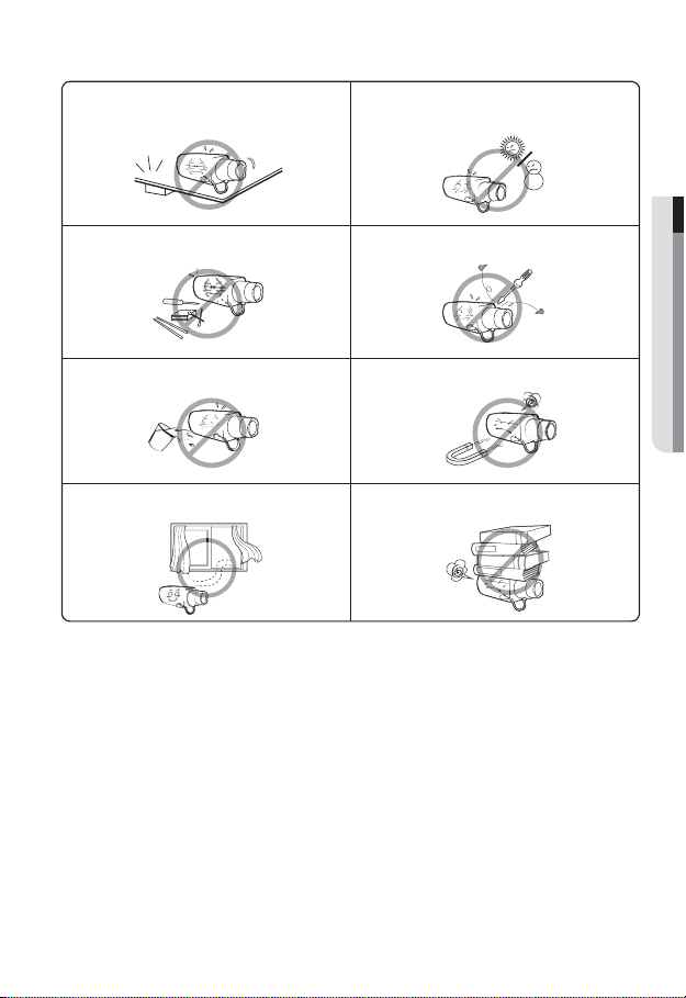
Please read the following recommend safety precautions carefully.
Do not Place this apparatus on an uneven surface. Do not install on a surface where it is exposed to direct
Do not place this apparatus near. Do not attempt to service this apparatus yourself.
Do not place a glass of water on the product. Do not install near any magnetic sources.
Do not block any ventilation openings. Do not place heavy items on the product.
sunlight, near heating equipment or heavy cold area.
User’s Manual is a guidance book how to use the products
The meaning of the using sign in the book is following
y
Reference : In case of providing information for helping of product’s usages
y
Notice : If there’s any possibility to occur any damages for the goods and
human caused by not following the instruction
Ú
Please read this manual for the safety before using of goods and keep it in
the safe place.
overview
Samsung Techwin cares for the environment at all product manufacturing stages, and is
taking measures to provide customers with more environmentally friendly products.
The Eco mark represents Samsung Techwin’s devotion to creating environmentally friendly
products, and indicates that the product satisfies the EU RoHS Directive.
Correct Disposal of This Product (Waste Electrical & Electronic Equipment)
(Applicable in the European Union and other European countries with separate collection
systems)
This marking on the product, accessories or literature indicates that the product and its
electronic accessories (e.g. charger, headset, USB cable) should not be disposed of with other
household waste at the end of their working life. To prevent possible harm to the environment
or human health from uncontrolled waste disposal, please separate these items from other
types of waste and recycle them responsibly to promote the sustainable reuse of material
resources.
Household users should contact either the retailer where they purchased this product, or
their local government office, for details of where and how they can take these items for
environmentally safe recycling.
Business users should contact their supplier and check the terms and conditions of the
purchase contract. This product and its electronic accessories should not be mixed with other
commercial wastes for disposal.
This equipment has been tested and found to comply with the limits for a
Class A digital device, pursuant to part 15 of the FCC Rules. These limits are
designed to provide reasonable protection against harmful interference when
the equipment is operated in a commercial environment.
This equipment generates, uses, and can radiate radio frequency energy and,
if not installed and used in accordance with the instruction manual, may cause
harmful interference to radio communications. Operation of this equipment in a
residential area is likely to cause harmful interference in which case the user will
be required to correct the interference at his own expense.
6_ overview

English _7
M OVERVIEW
CONTENTS
OVERVIEW
2
INSTALLATION & CONNECTION
24
NETWORK CONNECTION
AND SETUP
42
2 Important Safety Instructions
9 Product Features
9 Recomended PC Specifications
10 What’s Included
12 At a Glance (SNB-5000)
15 At a Glance (SND-5080)
18 At a Glance (SND-5080F)
21 At a Glance (SNV-5080)
24 Installation (SND-5080)
26 Installation (SND-5080F)
28 Installation (SNV-5080)
32 Mounting the Lens
33 Inserting/Removing an SD
Memory Card
36 Memory Card Information (Not
Included)
37 Connecting with other Device
42 Connecting the Camera Directly
to Local Area Networking
43 Connecting the Camera Directly
to a DHCP Based DSL/Cable
Modem
44 Connecting the Camera Directly
to a PPPoE Modem
45 Connecting the Camera to an
IP Router with the PPPoE/Cable
Modem
46 IP Address Setup
47 Static IP Setup
50 Dynamic IP Setup
51 Port Range Forward (Port
Mapping) Setup
52 Connecting to the Camera from a
Shared Local PC
52 Connecting to the Camera from a
Remote PC via the Internet

overview
CAMERA SETUP
53
WEB VIEWER
62
SETUP SCREEN
70
APPENDIX
87
53 How to use the Menu Key
53 Camera Menu Setup
62 Connecting to the Camera
63 Login
64 Installing Silverlight Runtime
66 Using the Live Screen
67 Using OSD Screen Menu
68 Playback
70 Setup
70 Audio & Video Setup
73 Network Setup
77 Event Setup
83 System Setup
87 Camera Specification
89 Network Specification
91 Troubleshooting
93 GPL/LGPL Software License
8_ overview

English _9
M OVERVIEW
PRODUCT FEATURES
y
HD Video Quality
Supports up to 1.3 mega pixels of HD video quality.
y
H.264/MPEG-4/MJPEG Multi-Streaming
This network camera supports the H.264/MPEG-4/MJPEG codec and can display videos
in different resolutions and qualities simultaneously with different Codecs.
y
Support various communication protocols
Supports TCP/IP, UDP, RTP/RTSP, email, and FTP protocols as well as various
internet protocols such as ARP, HTTP, HTTPS and DHCP.
y
Web Browser-based Monitoring
Using the Internet web browser to display the image in a local network environment.
y
Alarm
If an event occurs, the event-related video will be transferred to the FTP/email specified by
the user or saved to the SD memory, or the event signal will be sent to the ALARM OUT
port.
y
Intelligent Video Analysis
Analyzes the event video according to the user-specified rules to recognize the event.
y
ONVIF (Spec 1.01) Compliance
This product supports ONVIF Core Spec. 1. 01.
For more information, refer to www.onvif.org.
RECOMENDED PC SPECIFICATIONS
y
CPU : Pentium4 / 2.4GHz or higher
y
Operating System : Windows XP, VISTA, 7
y
Resolution : 1280X1024 pixels or higher
y
RAM : 1GB or higher
y
Web Browser : Internet Explorer 7.0 or higher
y
Video Memory : 128MB or higher
Mac OS
Firefox, Google Chrome, Safari
overview
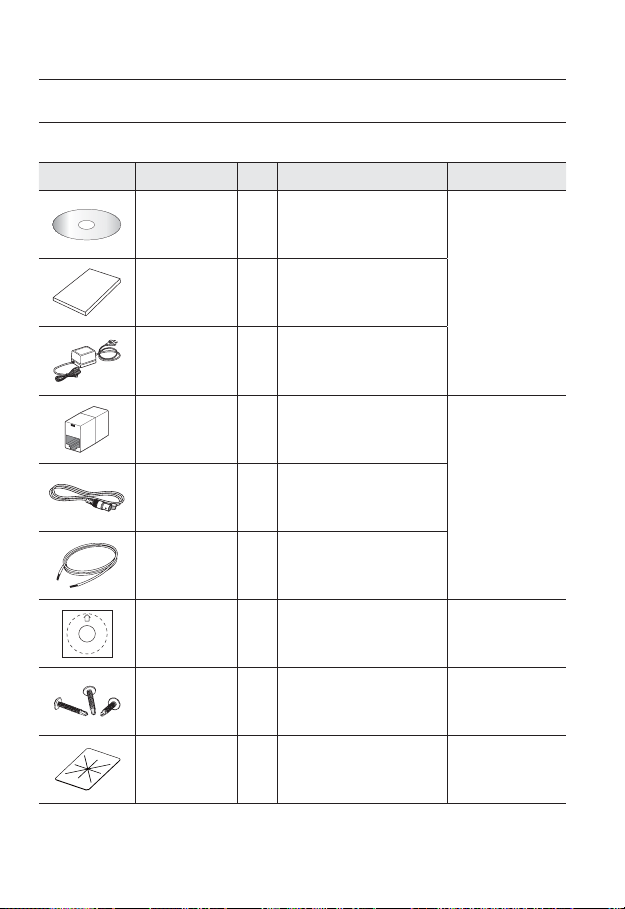
WHAT’S INCLUDED
Please check if your camera and accessories are all included in the product package.
Appearance Item Name
Quantity
Description Model Name
User Manual/
IP Installer DVD
User Manual 1
Power Adapter 1
Jack Modular 1 LAN cable gender
Cable for the testing
monitor
Alarm Cable 1 Used to connect to Alarm I/O
Template 1 Product installation guide
Iron Screw 3 Used for fixing to an iron plate SND-5080/5080F
Dustproof Plate 1 Preventing dust inflow SND-5080
1
Used for connecting to the power
source
Used to test the camera connection
1
to a portable display device
SNB-5000
SND-5080/5080F
SNV-5080
SND-5080/5080F
SNV-5080
SND-5080F
SNV-5080
10_ overview
English _11
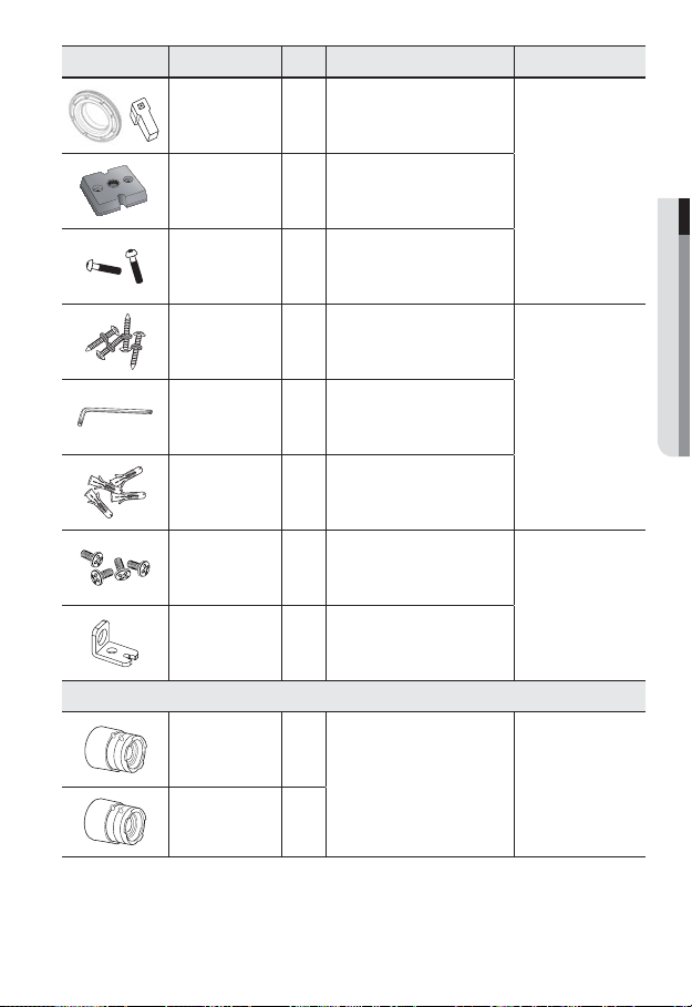
M OVERVIEW
Appearance Item Name
C Mount Adapter
Auto Iris Lens
Connector
Quantity
Used to install the camera lens
1
Description Model Name
Camera Holder
(Mount)
Camera Holder
(Mount) Screws
ASSY-Screw Tapping
L Wrench
Plastic Anchor
Tapping Screw
Bracket Safety
CS Lens
C Lens
Used to install the camera holder
1
Used to install the mount
2
Used for installation on the wall or
4
1
For fixing a screw, Inserted in a hole
4
Lens Options (not included)
ceiling
Used to remove/fix the dome cover
(reinforced anchoring force)
Optional lens to be inserted in a
camera
SNB-5000
SNV-5080
SND-5080F
SNB-5000
The Test Monitor Cable is connected to a portable displayer and used for testing the camera.
M
If you intend to use it for an actual monitoring camera, use the BNC cable instead.
overview
www.samsungcctv.com
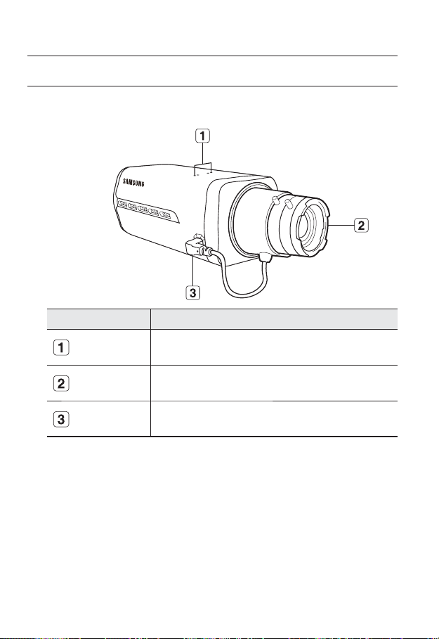
SNB-5000
AT A GLANCE (SNB-5000)
Front Side
Item Description
Camera Holder
(Mount) Holes
Used when you mount the camera onto the bracket by fixing the camera
holder (mount) adaptor with the bracket.
M
12_ overview
Auto Iris Lens
(Optional)
Auto Iris Lens
Connector
Wipe out a dirty surface of the lens softly with a lens tissue or cloth to which you have applied
ethanol.
Installed on the lens adaptor.
Used to supply power and output signal to control the iris of the lens.
English _13
M OVERVIEW
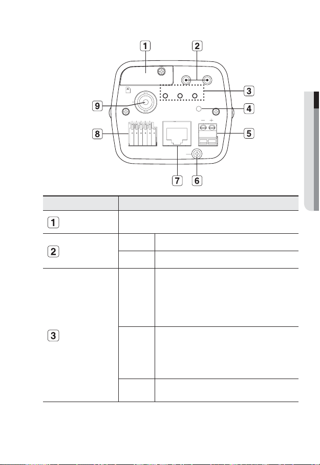
Rear Side
SD Memory Card
Compartment
Audio terminal
System, Power,
SD Indicators
AUDIO IN
SD SYSTEM POWER
NETWORK
-
ACT
AUDIO OUT
LINK
GND
RESET
AC 24V
DC 12V
SD CARD
VIDEO
1 2 3 4 5
1 : ALARM IN 4 :
2 : ALARM OUT 5 : GND
3 : ALARM COM
Item Description
Compartment for the SD memory card.
AUDIO OUT Terminal for audio output.
AUDIO IN Terminal for audio input.
ON : A memory card is inserted and operates normally.
Flashing : Failed to record, insufficient space, or inserted
SD
abnormally.
OFF : Camera is off, camera is restarting, or memory card is
not in place.
ON : The camera is turned on and connected to the network
properly.
SYSTEM
Blinking : During DDNS setup, or in case of setup failure, or
in a state of unstable network connection
OFF : When the system is rebooting, or turned off
POWER
ON : While the power is on
OFF : If the power is off
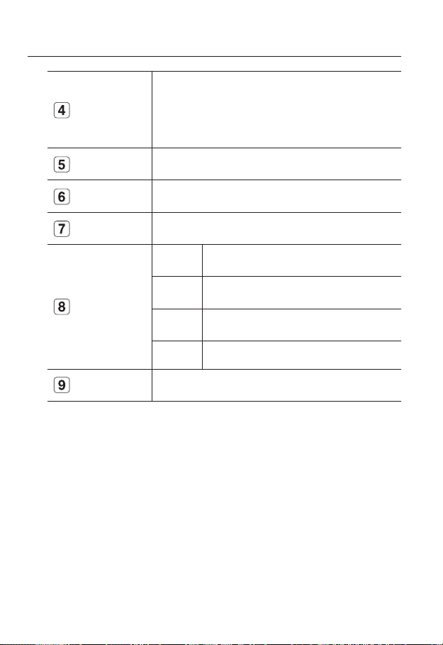
overview
Reset Button
Power Port Used to plug the power cable.
GND Used for earth-grounding.
Resets the camera settings to the default. Press and hold it for about 5
seconds to turn off the system indicator and restart the system.
J
Resetting the camera requires reconfiguration of network settings (IP
address, subnet mask, gateway address etc.) using the IP Installer
software application.
Network Port
I/O Port
Video Out Port
14_ overview
Used to connect a PoE or LAN cable.
ALARM IN Used to connect the alarm input signal.
ALARM OUT Used to connect the alarm output signal.
ALARM COM Common port where the alarm output signal is connected.
GND Used for earth-grounding.
Video signal output port connected to the monitor.
English _15
M OVERVIEW
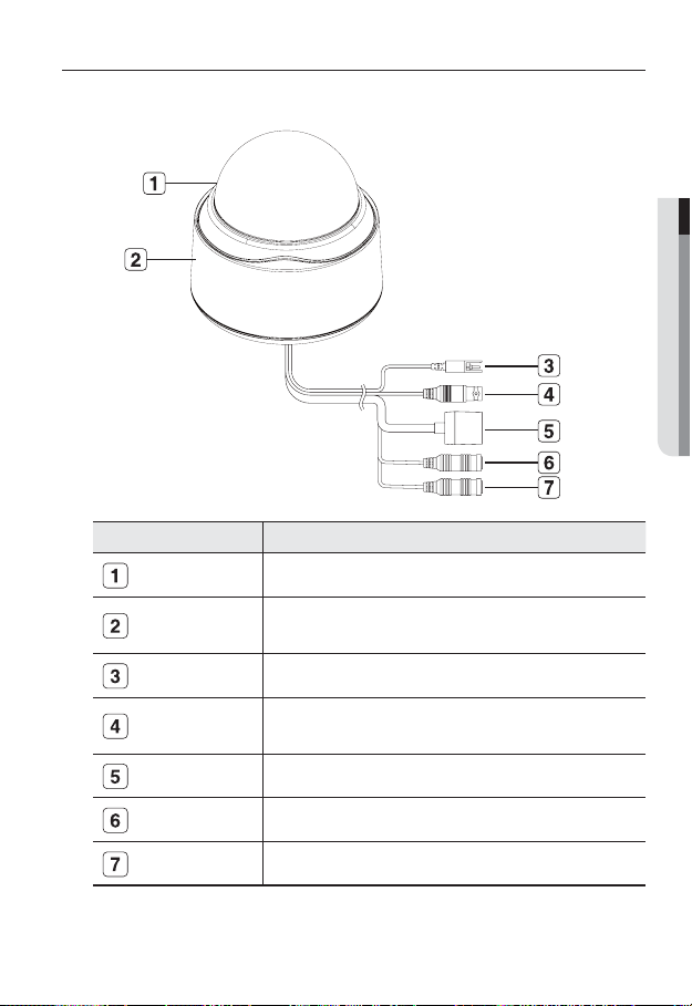
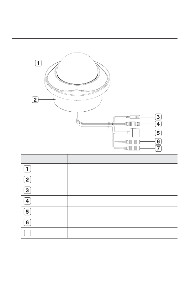
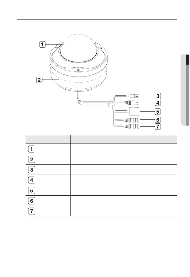
AT A GLANCE (SND-5080)
Appearance
Item Description
Dome Cover Dome cover for the lens and unit protection.
Main unit Main unit includes the lens, switch board, PCB boards and screws.
Power Port Used to plug the power cable.
Video Out Port Video signal output port connected to the monitor.
Network Port Used to connect a PoE or LAN cable.
Audio In Jack Used to connect to a microphone.
Audio Out Jack Used to connect to speakers.
overview
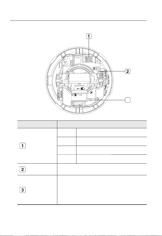
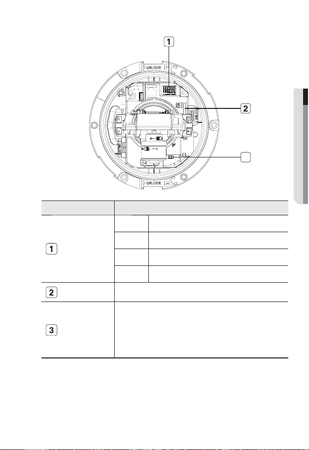
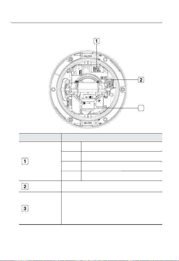
Inside
Item Description
3
ALARM IN Used to connect the alarm input signal.
Alarm In / Out
terminals
SD Memory Card
Compartment
Reset Button
16_ overview
ALARM OUT Used to connect the alarm output signal.
ALARM COM Common port where the alarm output signal is connected.
GND Used for earth-grounding.
Compartment for the SD memory card.
Resets the camera settings to the default. Press and hold it for about 5
seconds to turn off the system indicator and restart the system.
J
Resetting the camera requires reconfiguration of network settings (IP
address, subnet mask, gateway address etc.) using the IP Installer
software application.
English _17
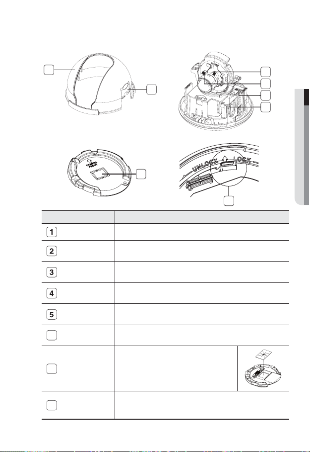
M OVERVIEW
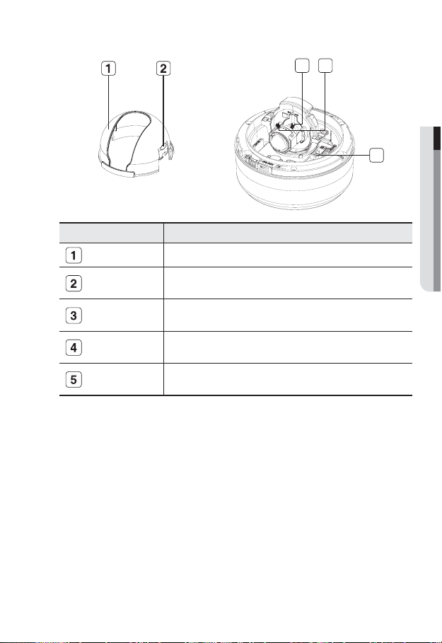
Components
1
2
7
Item Description
Inner Cover Cover for the main unit’s protection.
Side wing hooks
ZOOM lever
Focus lever
SD Memory Card
Compartment
Monitor Out
6
Wiring Cover
7
Lock Release
8
By lifting it while gently pressing the both ends, you can separate the inner
cover.
Turn the barrel left or right to adjust the zoom, and turn the knob clockwise
to lock the zoom.
Turn the barrel left or right to adjust the focus, and turn the knob clockwise
to lock the focus.
Compartment for the SD memory card.
Using the test monitor cable, you can connect to a mobile display for camera
test.
If you drill a hole in the wiring cover for wiring,
remove the cover and attach the provided dustproof
plate to it, and arrange the cables through the plate.
The dust-proof plate is to prevent outside dust from
inflow to the wiring compartment.
To separate the bracket from the main unit for the installation or to separate
the camera from an installed camera, push this release and turn the main
unit in the marked direction of <UNLOCK>.
3
4
5
6
8
overview
AT A GLANCE (SND-5080F)
Appearance
Item Description
Dome Cover Dome cover for the lens and unit protection.
Main unit Main unit includes the lens, switch board, PCB boards and screws.
Power Port Used to plug the power cable.
Video Out Port Video signal output port connected to the monitor.
Network Port Used to connect a PoE or LAN cable.
Audio In Jack Used to connect to a microphone.
Audio Out Jack Used to connect to speakers.
7
18_ overview
English _19
M OVERVIEW
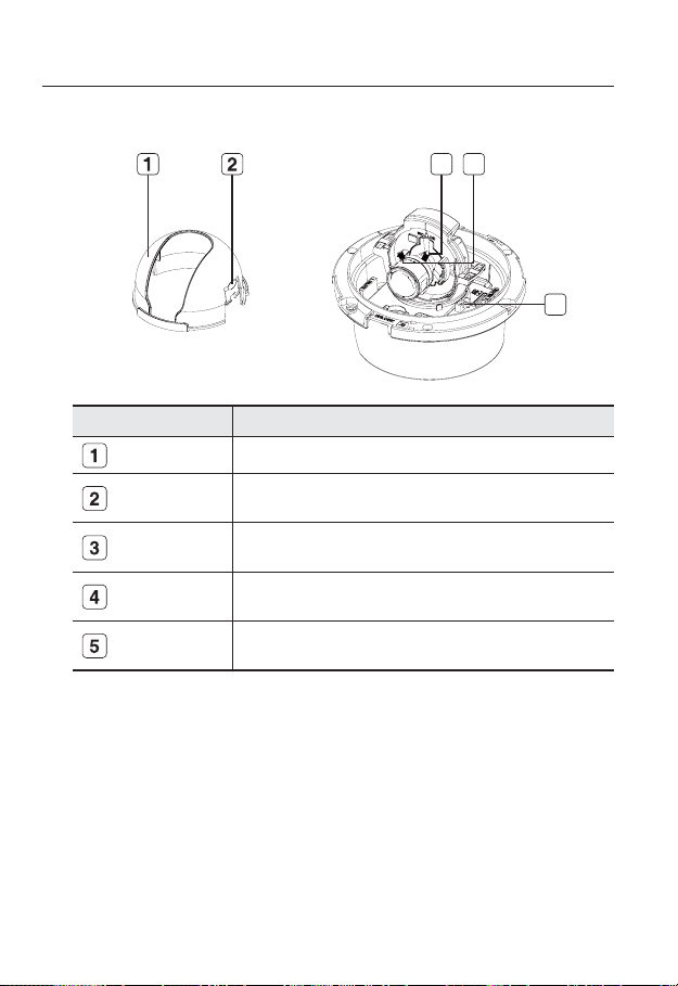
Inside
3
Item Description
ALARM IN Used to connect the alarm input signal.
Alarm In / Out
terminals
SD Memory Card
Compartment
Reset Button
ALARM OUT Used to connect the alarm output signal.
ALARM COM
GND Used for earth-grounding.
Compartment for the SD memory card.
Resets the camera settings to the default. Press and hold it for about 5
seconds to turn off the system indicator and restart the system.
J
Common port where the alarm output signal is connected.
Resetting the camera requires reconfiguration of network settings (IP
address, subnet mask, gateway address etc.) using the IP Installer
software application.
overview
Components
Item Description
Inner Cover Cover for the main unit’s protection.
Side wing hooks
ZOOM lever
Focus lever
Monitor Out
3 4
5
By lifting it while gently pressing the both ends, you can separate the inner
cover.
Turn the barrel left or right to adjust the zoom, and turn the knob clockwise
to lock the zoom.
Turn the barrel left or right to adjust the focus, and turn the knob clockwise
to lock the focus.
Using the test monitor cable, you can connect to a mobile display for camera
test.
20_ overview
English _21
M OVERVIEW
AT A GLANCE (SNV-5080)
Appearance
Item Description
Dome Cover Dome cover for the lens and unit protection.
Main unit Main unit includes the lens, switch board, PCB boards and screws.
Power Port Used to plug the power cable.
Video Out Port Video signal output port connected to the monitor.
Network Port Used to connect a PoE or LAN cable.
Audio In Jack Used to connect to a microphone.
Audio Out Jack Used to connect to speakers.
overview
Inside
Item Description
3
ALARM IN Used to connect the alarm input signal.
Alarm In / Out
terminals
SD Memory Card
Compartment
Reset Button
22_ overview
ALARM OUT Used to connect the alarm output signal.
ALARM COM
GND Used for earth-grounding.
Compartment for the SD memory card.
Resets the camera settings to the default. Press and hold it for about 5
seconds to turn off the system indicator and restart the system.
J
Common port where the alarm output signal is connected.
Resetting the camera requires reconfiguration of network settings (IP
address, subnet mask, gateway address etc.) using the IP Installer
software application.
English _23
M OVERVIEW
Components
Item Description
Inner Cover Cover for the main unit’s protection.
Side wing hooks
ZOOM lever
Focus lever
Monitor Out
By lifting it while gently pressing the both ends, you can separate the inner
cover.
Turn the barrel left or right to adjust the zoom, and turn the knob clockwise
to lock the zoom.
Turn the barrel left or right to adjust the focus, and turn the knob clockwise
to lock the focus.
Using the test monitor cable, you can connect to a mobile display for camera
test.
3 4
5
installation & connection
INSTALLATION (SND-5080)
Precautions before installation
Ensure you read out the following instructions before installing the camera:
y
Select an installation site (ceiling or wall) that can endure at least 5 times of the camera
weight.
y
Stuck-in or peeled-off cables can cause damage to the product or a fire.
y
For safety purposes, keep anyone else away from the installation site.
And put aside personal belongings from the site, just in case.
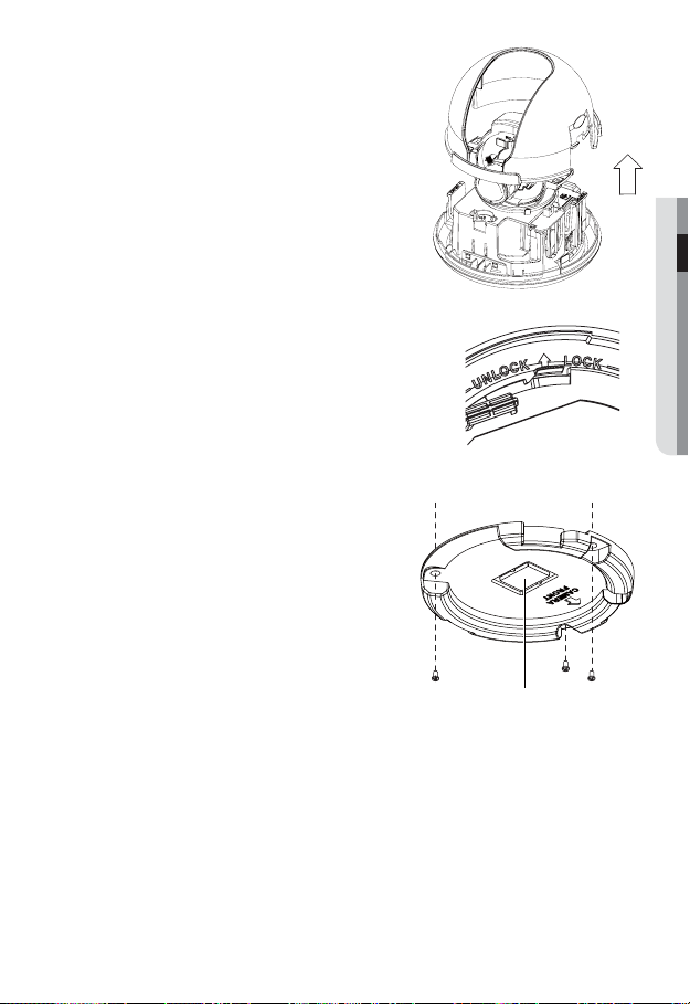
Installing the camera
Hold down the bottom lock lever while
1.
removing the cover with the other hand.
Removing the cover reveals the main unit
and inner cover.
24_ installation & connection
English _25
M INSTALLATION & CONNECTION
To fix the camera position, hold down either
2.
hook of the inner cover and lift it up.
Push the release lock out while turning the main unit in
3.
the <UNLOCK> direction to remove the bracket.
If this doesn't work, use the hole on the bottom of the
bracket to turn the bracket in the <LOCK>direction.
Use the provided screws (x3) to fix the bracket to a
4.
desired position (ceiling or wall).
Ensure that the <CAMERA FRONT> label on the bracket faces
the direction for camera monitoring.
5.
Arrange the cables through the bracket to the
ceiling or wall.
If you drill a hole in the ceiling cover for wiring,
press hard to remove the cover and attach the
dust-proof plate to it, and arrange the cables
through the plate. If you intend to arrange the
cables without drilling a hole, use the empty
area opposite to the <CAMERA FRONT>
label side for the wiring purpose.
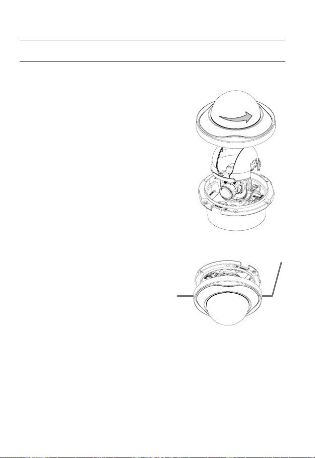
6.
Mount the main unit onto the bracket.
Align the marking hole of the main unit with the
<CAMERA FRONT> label of the bracket, and
turn the unit in the <LOCK> direction.
7.
Adjust the lens in a desired direction.
For adjusting the lens direction, refer to "Adjusting the monitoring direction for
the camera". (page 31)
8.
Secure the inner cover to the main unit.
Fit the two holes of the wing-side locks on the inner cover into the corresponding
hole of the main unit, and press it down until you hear a click.
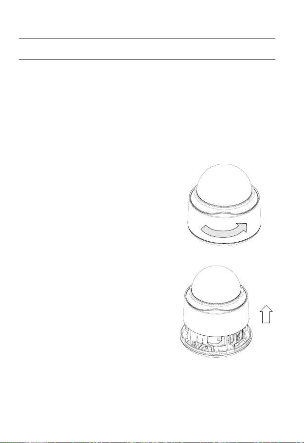
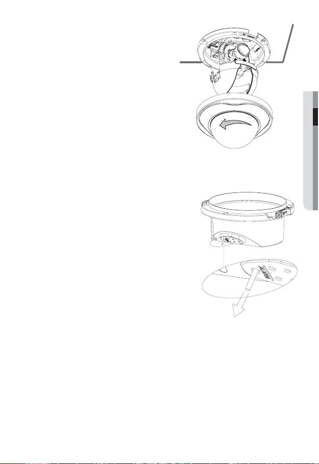
9.
Fix the cover to the main unit.
Fit the protruding part inside the cover into the corresponding hole of the main unit,
and turn the cover to fix it.
Wiring Cover
installation & connection
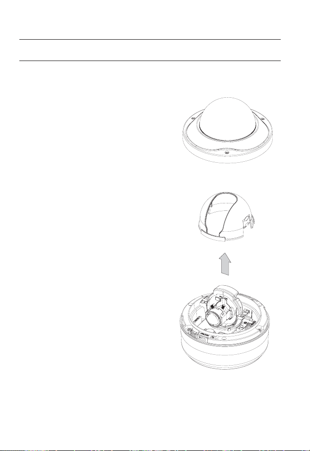
INSTALLATION (SND-5080F)
Removing the dome cover
Hold down the bottom lock lever while removing
1.
the cover with the other hand. Removing the
cover reveals the main unit and inner cover.
To fix the camera position, hold down both
2.
hooks of the inner cover while lifting it up.
Ceiling Mount
Use the provided template to drill one hole
1.
for the camera, and one for the screw (5
mm in diameter, at least 35 mm in depth),
and insert the plastic anchor (HUR 5) to the
end of the screw hole.
Connect and arrange the necessary cables
2.
(power, video, etc) lest that they should
be damaged or caught while installing the
camera.
26_ installation & connection
English _27
M INSTALLATION & CONNECTION
Insert the camera assembly into the hole
3.
so that it fits to the camera hole, and fix
the assembly using the assembly screw
tappings (TH, M4xL30). (x3)
Close the dome cover.
4.
Fix the cover to the main unit. Fit the
5.
protruding part inside the cover into the
corresponding hole of the main unit, and
turn the cover to fix it.
To add an alarm cable
1.
For this, first you should remove the dome
cover from the housing.
2.
Pull out the protruding rubber bar as shown.
3.
This will reveal a hole in the place of the rubber
bar, through which you insert the cable, and
connect it to the alarm terminal on the PCB.
4.
Connect and arrange the necessary cables
(power, video, etc) lest that they should be
damaged or caught while installing the camera.
Then, install the camera assembly in the
reverse order of the disassembly.
5.
Adjust the lens in a desired direction and close
the dome cover.
installation & connection
INSTALLATION (SNV-5080)
Disassembling
To connect the alarm in/out, the dome cover and lens cover are to be separated.
Using the L-wrench provided, loosen 3
1.
screws by turning them counterclockwise
and separate the dome cover.
Lift up the inner cover while gently pressing
2.
its both ends to separate it from the unit.
28_ installation & connection
English _29
M INSTALLATION & CONNECTION
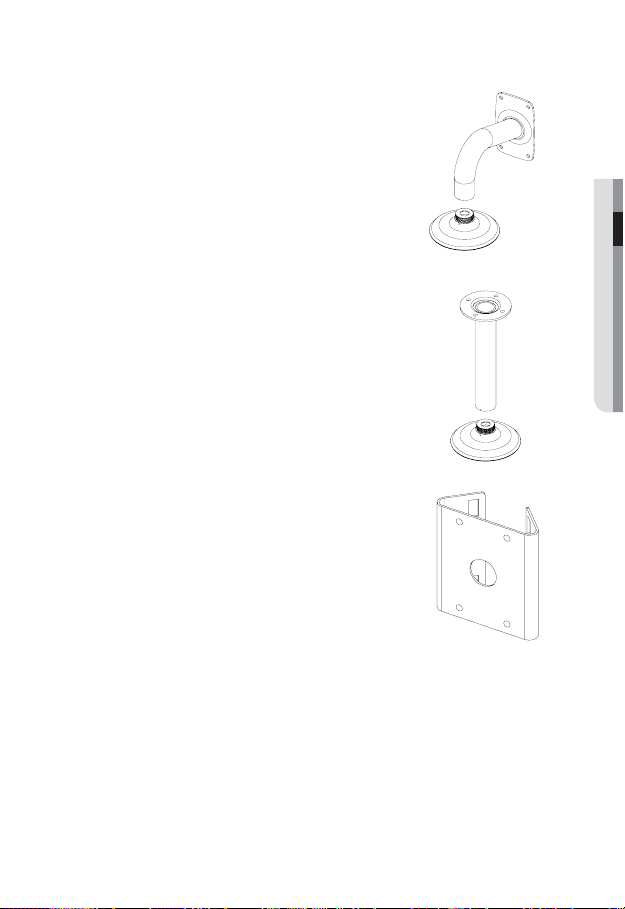
Optional Accessories for Installation
For your easier installation, you can purchase appropriate optional accessories available.
1.
WALL MOUNT ADAPTOR(SCX-300WM)/
HANGING MOUNT(SCX-300HM)
This adaptor is used when installing the dome
camera onto a wall.
CEILING MOUNT ADAPTOR(SCX-300CM)/
2.
HANGING MOUNT(SCX-300HM)
This adaptor is used when installing the dome
camera on a concrete ceiling.
POLE MOUNT ADAPTOR(SCX-300PM)
3.
This is an adaptor for WALL MOUNT ADAPTOR
(SCX-300WM) installation on a pole whose
diameter is bigger than 80mm.
installation & connection
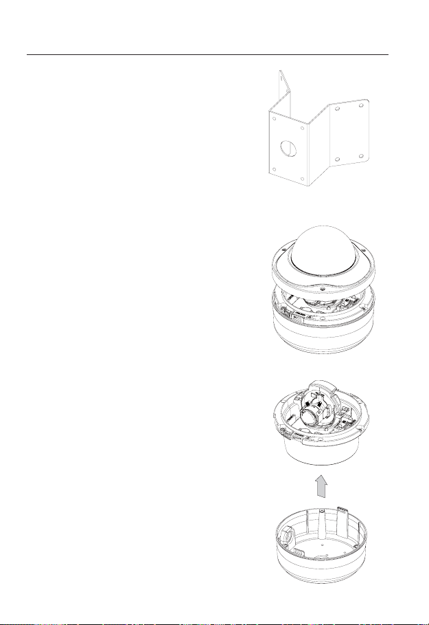
CORNER MOUNT ADAPTOR (SCX-300KM)
4.
This is an adaptor for WALL MOUNT
ADAPTOR (SCX-300WM) installation on the
corner of wall joint.
Installing on the ceiling directly
Using the L-wrench provided, loosen 3 screws
1.
by turning them counterclockwise and separate
the dome cover.
Loosen 3 screws by turning them
2.
counterclockwise, press both left and right lock
releases inwards (in arrow direction) to unlock
the stopper, and then separate the camera
from the case.
30_ installation & connection
 Loading...