

Samsung SNC-C6225, SNC-C7225 User Manual

SNC-C6225
SNC-C7225
10x Network Mini Smart
Dome Camera
User Manual
imagine the possibilities
Thank you for purchasing this Samsung product.
To receive more complete service,
Please visit our website.
www.samsungsecurity.com
safety information
CAUTION
RISK OF ELECTRIC SHOCK.
DO NOT OPEN
CAUTION: TO REDUCE THE RISK OF ELECTRIC SHOCK, DO NOT REMOVE COVER (OR BACK) NO USER SERVICEABLE PARTS
INSIDE. REFER SERVICING TO QUALIFIED SERVICE PERSONNEL.
This symbol indicates that dangerous voltage consisting a risk of electric shock is present
within this unit.
This exclamation point symbol is intended to alert the user to the presence of important
operating and maintenance (servicing) instructions in the literature accompanying the
appliance.
WARNING
To reduce the risk of fi re or electric shock, do not expose this appliance to rain or moisture.
•
To prevent injury, this apparatus must be securely attached to the fl oor/wall in accordance with the installation
•
instructions.
If this power supply is used at 12V DC, a suitable plug adapter should be used.
•
WARNING
1.
Be sure to use only the standard adapter that is specifi ed in the specifi cation sheet.
Using any other adapter could cause fi re, electrical shock, or damage to the product.
2.
Incorrectly connecting the power supply or replacing battery may cause explosion, fi re, electric shock, or damage
to the product.
3.
Do not connect multiple cameras to a single adapter. Exceeding the capacity may cause abnormal heat generation
or fi re.
4.
Securely plug the power cord into the power receptacle. Insecure connection may cause fi re.
5.
When installing the camera, fasten it securely and fi rmly. The fall of camera may cause personal injury.
6.
Do not place conductive objects (e.g. screwdrivers, coins, metal parts, etc.) or containers fi lled with water on top of
the camera. Doing so may cause personal injury due to fi re, electric shock, or falling objects.
7.
Do not install the unit in humid, dusty, or sooty locations. Doing so may cause fi re or electric shock.
8.
If any unusual smells or smoke come from the unit, stop using the product. In such case, immediately disconnect
the power source and contact the service center. Continued use in such a condition may cause fi re or electric
shock.
9.
If this product fails to operate normally, contact the nearest service center. Never disassemble or modify this product in
any way. (SAMSUNG is not liable for problems caused by unauthorized modifi cations or attempted repair.)
10.
When cleaning, do not spray water directly onto parts of the product. Doing so may cause fi re or electric shock
If the camera is installed or rebooted after power failure when ambient temperature is below the freezing point, the
11.
dome cover is frosted. In this case, the frost will be disappeared after 3 hours after turning on the power.
(It is noted that lowest guaranteed operating temperature is -45ºC(-49ºF) without wind.).
2 – 10x Network Mini Smart Dome Camera

safety information
Do not expose the product to the direct airfl ow from an air conditioner.
12.
Otherwise, it may cause moisture condensation inside the Clear Dome due to temperature difference between
internal and external of the dome camera.
13.
If you install this product in a low-temp area such as inside a cold store, you must seal up the wiring pipe with
silicon, so that the external air can not fl ow inside the housing.
Otherwise, external high, humid air may fl ow inside the housing, pooling moisture or vapor inside the product due
to a difference between internal and external temperature.
CAUTION
Do not drop objects on the product or apply strong blows to it. Keep away from a location subject to excessive
1.
vibration or magnetic interference.
Do not install in a location subject to high temperature (over 140°F), low temperature (below -49°F), or high humidity.
2.
Doing so may cause fi re or electric shock.
If you want to relocate the already installed product, be sure to turn off the power and then move or reinstall it.
3.
Remove the power plug from the outlet when there is a lighting storm. Neglecting to do so may cause fi re or
4.
damage to the product.
Keep out of direct sunlight and heat radiation sources. It may cause fi re.
5.
Install it in a place with good ventilation.
6.
Avoid aiming the camera directly towards extremely bright objects such as sun, as this may damage the CCD image
7.
sensor.
Apparatus shall not be exposed to dripping or splashing and no objects fi lled with liquids, such as vases, shall be
8.
placed on the apparatus.
The Mains plug is used as a disconnect device and shall stay readily operable at any time.
9.
FCC Statement
This device complies with part 15 of the FCC Rules. Operation is subject to the following two conditions :
1) This device may not cause harmful interference, and
2) This device must accept any interference received including interference that may cause undesired operation.
Caution
This equipment has been tested and found to comply with the limits for a Class A digital device, pursuant to part 15 of FCC Rules.
These limits are designed to provide reasonable protection against harmful interference when the equipment is operated in a commercial environment.
This equipment generates, uses, and can radiate radio frequency energy and, if not installed and used in accordance with the
instruction manual, may cause harmful interference to radio communications. Operation of this equipment in a residential area is
likely to cause harmful interference in which case the user will be required to correct the interference at his own expense.
IC Compliance Notice
This Class A digital apparatus meets all requirements of the Canadian Interference.-Causing Equipment
Regulations of ICES-003.
English – 3
important safety instructions
Read these instructions.
1.
Keep these instructions.
2.
3.
Heed all warnings.
4.
Follow all instructions.
5.
Do not use this apparatus near water.
6.
Clean only with dry cloth.
7.
Do not block any ventilation openings. Install in accordance with the manufacturer’s instructions.
8.
Do not install near any heat sources such as radiators, heat registers, or other apparatus (including amplifi ers) that
produce heat.
9.
Do not defeat the safety purpose of the polarized or grounding-type plug. A polarized plug has two blades with
one wider than the other. A grounding type plug has two blades and a third grounding prong. The wide blade or
the third prong is provided for your safety. If the provided plug does not fi t into your outlet, consult an electrician for
replacement of the obsolete outlet.
10.
Protect the power cord from being walked on or pinched particularly at plugs, convenience
receptacles, and the point where they exit from the apparatus.
11.
Only use attachments/accessories specifi ed by the manufacturer.
12.
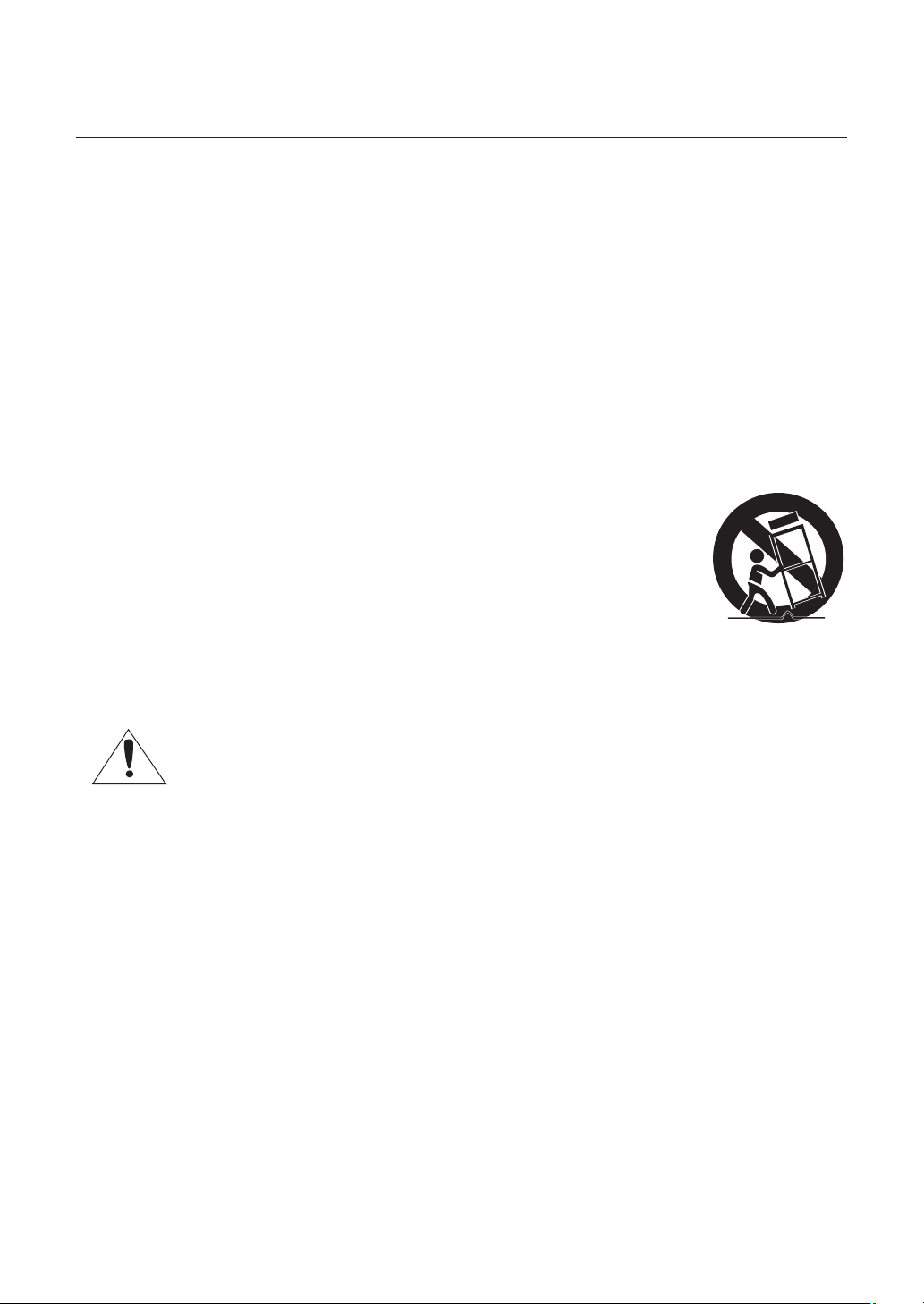
Use only with cart, stand, tripod, bracket, or table specifi ed by the manufacturer, or sold with
the apparatus.
13.
Unplug this apparatus when a card is used. Use caution when moving the cart/ apparatus
combination to avoid injury from tip-over.
14.
Refer all servicing to qualifi ed service personnel. Servicing is required when the apparatus has been damaged in
any way, such as powersupply cord or plug is damaged, liquid has been spilled or objects have fallen into the
apparatus, the apparatus has been exposed to rain or moisture, does not operate normally, or has been dropped.
Apparatus shall not be exposed to dripping or splashing and no objects fi lled with liquids, such
as vases, shall be placed on the apparatus
4 – 10x Network Mini Smart Dome Camera

contents
Introduction
Features 7
Recommended PC Specifi cations 8
Compatible IP Routers 8
Product & Accessories 9
Parts Name & Functions 11
Installation
DIP Switch Setup 13
Installation Using Surface Mount On The Ceiling 14
Installation Using Ceiling Mount Bracket 15
Installation Using Wall Mount Bracket 16
Cabling 17
Inserting/Removing an micro SDHC Memory Card 19
Memory Card Information (not included) 20
Operation
Check points before operation 21
Preset and Pattern Function Pre-Check 21
Auto Calibration 21
Starting OSD Menu 21
Reserved Preset 21
Preset 22
Auto Pan 22
Pattern 22
Scan 23
Schedule 23
Other Functions 23
OSD Display of Main Screen 24
General Rules of Key Operation for Menu 24
How to use OSD menu
Structure of the Setup Menu 25
Main Menu 27
System Information 27
Display Setup 27
Privacy Zone Mask Setup 27
Motion Setup 28
Function Setup 29
Preset Setup 30
Auto Pan Setup 31
Pattern Setup 31
Scan Setup 32
Schedule Setup 34
Camera Setup 35
System Setup 36
System Initialize 38
English – 5

contents
Network connection & Setup
Connecting the camera to an IP router with the xDSL/Cable modem 39
Connecting the camera to an IP router with local area networking 41
Connecting the camera directly to a DHCP-based xDSL/Cable modem 43
Connecting the camera directly to local area networking 44
Searching for the camera 45
Setting Static IP
Manual Network Setting 46
Automatic Network Setting 48
Setting Dynamic IP
Dynamic IP Setting 49
Port Forwarding (Port Mapping) Setting 49
Using the camera
Connecting to the camera 50
Installing ActiveX 51
Web Viewer
Main Screen 53
using the camera 54
Using the SD Search Viewer Screen 56
Setup Tool
Setting the camera 57
Video & Audio Confi guration 58
IP 59
User 60
Language 60
Digital Image Stabilizer 60
Date/Time 61
Log 61
Software Update 61
Reset 62
HTTPS 62
Transfer Setup 62
Record Setup 63
Alarm Image Setup 64
Alarm Input Setup 64
Motion 65
Schedule 66
Streaming Setup 66
DDNS 67
SNMP 68
Appendix
Troubleshooting 69
Specifi cations 71
Dimension 74
6 – 10x Network Mini Smart Dome Camera

FEATURES
Network Specifi cations
❖
•
Powerful Dual Stream by using DSP based
MPEG4, MJPEG compression
Superior Video Quality and System Stability.
•
High speed : Up to 30 fps at 720x480, 25 fps at
•
720x576.
•
Web Browser based viewer support.
Remote Pan/Tilt/Zoom control.
•
Bidirectional Audio support.
•
Support with DDNS Service (Samsung DDNS,
•
Public DDNS) for Dynamic IP.
Various protocol support. (ARP, HTTP, HTTPS,
•
DHCP, TCP/IP, UDP, RTP/RTSP, SMTP, FTP,
SNMP, etc)
IPv4/IPv6 support.
•
Alarm Function
•
Motion Detection Function
•
Micro SD Card Backup
•
Camera Specifi cations
❖
CCD Sensor : 1/4" Interline Transfer CCD
•
Zoom Magnifi cation : × 10 Optical Zoom, × 10
•
Digital Zoom (Max × 100 Zoom)
Day & Night Function : ICR (IR Cut fi lter Removal)
•
•
Various Focus Mode : Auto Focus / Manual Focus /
ONEAF Focus.
Independent or Global camera settings for each
•
Preset locations.
Powerful Pan/Tilt Functions
❖
Max. 360°/sec high speed Pan/Tilt Motion
•
Using Vector Drive Technology, Pan/Tilt motions
•
are accomplished in the shortest path. As a result,
time to target view is reduced dramatically and the
video on the monitor is very natural to watch.
Ultra low speed (0.05°/sec) enables operator to
•
locate camera to desired target view with accuracy
and ease.
Zoom-proportional pan/tilt speed helps operator to
•
move the camera easily.
Preset, Pattern, Auto Pan, Scan, Privacy
❖
Mask, Schedule and More…
Max. 127 Presets are assignable. All of them have
•
independent characteristics such as White Balance,
Auto Exposure, Label, Alarm Input/Output and so
on.
introduction
•
Max. 8 set of Auto Pan can be stored. This enables
to move camera repetitively between two preset
positions with designated speed.
•
Max. 4 of Patterns can be recorded and played back.
This enables to move camera to follow any trajectory
operated by joystick as closely as possible.
•
Max. 8 set of Scan action can be stored.
This enables to move camera repetitively with
combination of Preset or Pattern or Auto Pan.
A Scan is composed of max. 20 entities of Preset/
Pattern/Auto Pans.
•
Max. 4 Masks are settable independently to
protect privacy zone. The mask is arbitrary-sized
rectangular and locate any location in view space.
•
7 rules of Schedule can be assigned by day and
time. Appropriate actions (such as Home, Preset,
Scan, Pattern and Auto Pan) can be defi ned for
each rule. Also, it is possible to use Weekday and
All days to simplify the rule.
PTZ(Pan/Tilt/Zoom) Control
❖
With RS-485 communication, max. 255 of cameras
•
can be controlled at the same time.
OSD(On Screen Display) Menu
❖
OSD menu is provided to display the status of
•
camera and to confi gure the functions interactively.
Currently, 7 Languages are supported for
•
OSD Menu: [ENGLISH/ESPAÑOL/FRANÇAIS/
DEUTSCH/ITALIANO/РУССКИЙ/PORTUGUÊS]
The information such as Camera ID, Pan/Tilt/
•
Zoom/Direction, Alarm Input & Output, date/time,
Current temperature and Preset can be displayed
on screen.
Each display item can be turned on or off
•
independently.
Alarm I/O Functions
❖
2 alarm sensor Inputs and 1 relay output are
•
available.
•
To reject external electric noise and shock perfectly,
alarm sensor Input is decoupled with photo
coupler.
If an external sensor is activated, camera can be
•
set to move to the corresponding Preset position.
Relay outputs can be assigned to work with a
•
certain preset.
Reserved Presets for Special Purpose
❖
Most of camera settings are directly changed by
•
calling Reserved Presets, not entering into OSD
menu. For more information, refer to “Reserved
Preset” (page 21) in this manual.
English – 7

introduction
RECOMMENDED PC
SPECIFICATIONS
CPU : Pentium4/2.4GHz or higher
•
Operating System : Windows XP(Service Pack 2) /
•
Windows Vista
Resolution : 1024x768 pixels or higher
•
RAM : 512MB or higher
•
Web Browser : Internet Explorer 6.0 or higher
•
Video Card : Radeon, Nvidia
•
Video Memory : 128MB
•
DirectX 8.1 or higher
•
COMPATIBLE IP ROUTERS
Linksys
•
D-Link
•
Netgear
•
8 – 10x Network Mini Smart Dome Camera
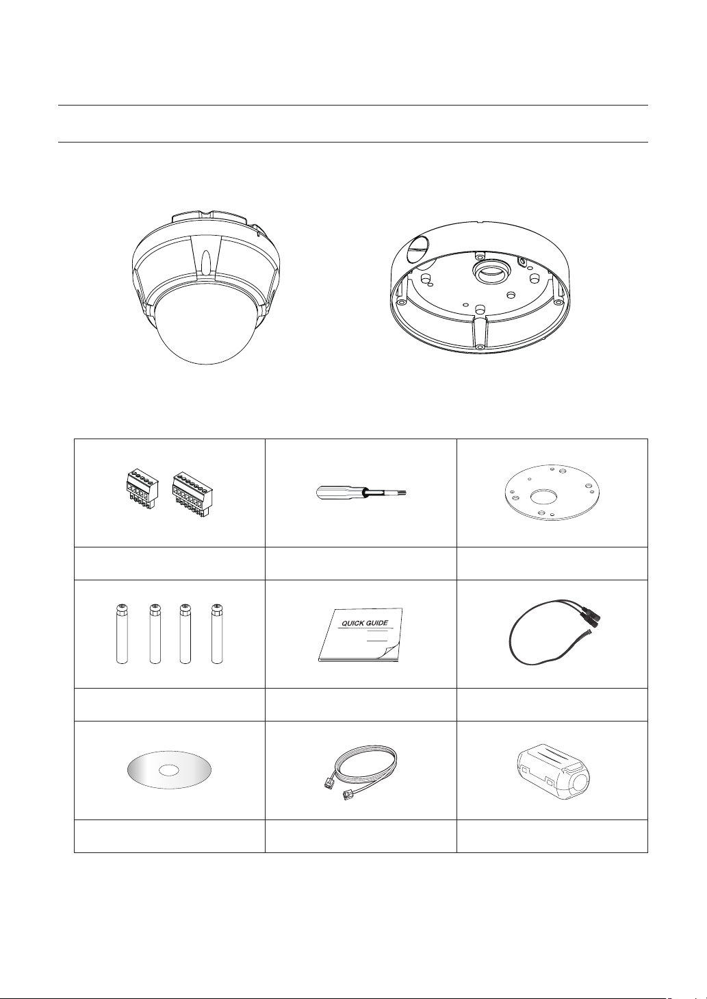
PRODUCT & ACCESSORIES
SNC-C6225
❖
Product
•
Main Body Surface Mount Bracket
Accessories
•
introduction
Terminal Block Torx Screw Driver Surface Mount Gasket
Screw & Plastic Anchor (4pcs)
User Manual / IP Installer CD Cross Cable Core Filter
Mount Bracket Option : Please use SADT-937WM for this purpose.
M
Quick Guide Audio Cable
English – 9
introduction
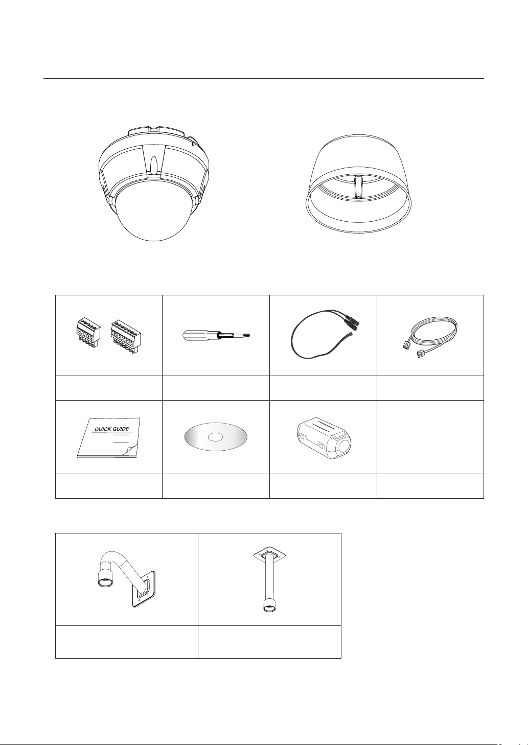
SNC-C7225
❖
Product
•
Main Body Sun Shield Housing
Accessories
•
Terminal Block Torx Screw Driver Audio Cable Cross cable
Quick Guide User Manual / IP Installer CD Core Filter
•
Mount Bracket Option
Wall Mount Bracket
(SADT-732WM)
Ceiling Mount Bracket
(SADT-732CM)
10 – 10x Network Mini Smart Dome Camera

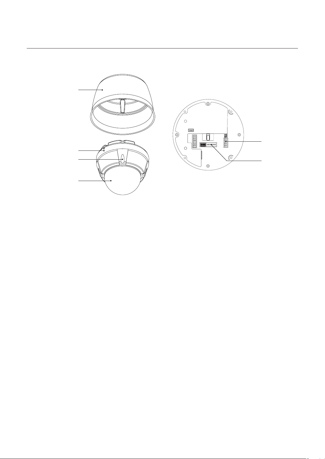
PARTS NAME & FUNCTIONS
SNC-C6225❖
Surface Mount Bracket
Mounting Hole
introduction
Main Body
Lockup Screw
Dome Cover
Main Unit / Surface Mount Bracket Back of Main Unit
Dome Cover
•
Do not remove the protection vinyl from dome cover
before fi nishing all installation process to protect dome
cover from scratches or dust.
Surface Mount Bracket
•
This is used to install the camera directly on the
ceiling. After separating this cover, mount this bracket
on to ceiling. Main body of the camera is going to be
assembled again in the last stage.
Do not use this bracket with wall mount bracket or
ceiling mount bracket.
Cabling Terminal
Block
DIP Switch
Lockup Screw
•
Fixes main unit brackets like surface, wall, and ceiling.
Cabling Terminal Block
•
During installation, Power, Video, Communication,
Alarm Input cables are connected on to this cabling
terminal block.
DIP Switch
•
Adjusts camera ID and protocols.
English – 11
introduction
SNC-C7225❖
Sun Shield Housing
Main Body
Lockup Screw
Dome Cover
Main Unit / Sun Shield Housing Back of Main Unit
Dome Cover
•
Do not remove the protection vinyl from dome cover
before fi nishing all installation process to protect dome
cover from scratches or dust.
Cabling Terminal
Block
DIP Switch
Cabling Terminal Block
•
During installation, Power, Video, Communication,
Alarm Input cables are connected on to this cabling
terminal block.
Sun Shield Housing
•
Lockup Screw
•
Fixes main unit brackets like surface, wall, and ceiling.
12 – 10x Network Mini Smart Dome Camera
DIP Switch
•
Adjusts camera ID and protocols.

DIP SWITCH SETUP
Installation
Communication Protocol Setup
❖
Before you install the camera, you should set the DIP
switches to confi gure the camera ID, Baud Rate and
communication protocol.
Protocol Baud Rate
w
WWWGaGhGw
0x00 : Auto Protocol
0x03 : SAMSUNG
WWZGaGzhtz|un
❖
Camera ID Setup
ON
ON
ID Setting (1~255)
pkGzGOX¥Y\\P
iGy
0x00 : 2400
WWWGaGY[WW
0x01 : 4800
WWXGaG[_WW
0x02 : 9600
WWYGaG`]WW
0x03 : 19200
WWZGaGX`YWW
0x04 : 38400
WW[GaGZ_[WW
RS-485
yzT[_\
Terminate
{
ON
ON
123456
Select the appropriate Protocol with DIP switch
•
78
combination.
Switch State
Pin1 Pin2 Pin3 Pin4
OFF OFF OFF OFF Auto Protocol
ON ON OFF OFF SAMSUNG
If you set the protocol as Auto Protocol, camera will
•
Protocol
automatically recognize the kind of Protocol.
If you want to control using DVR or system
•
keyboard, their protocol must be identical to
camera. Otherwise, you can not control the camera.
If you changed camera protocol by changing DIP
•
S/W, the change will be effective after you reboot
the camera.
Factory default of protocol is “Auto” Protocol.
•
Communication Baud rate Setup
❖
ON
ON
123456
ID number of camera is set using binary number.
•
78
The example is shown bellow.
Pin 12345678
ID Value 1 2 4 8 16 32 64 128
ex) ID=5
ex) ID=10ONOFF
•
The range of ID is 0~255. Factory default of
OFFONON
OFF
OFFONOFF
OFF
OFF
OFF
OFF
OFF
Camera ID is 1.
•
If you want to control a certain camera, you must
match the camera ID with Cam ID setting of DVR or
Controller.
OFF
OFF
123456
Select the appropriate Baud rate with DIP switch
•
78
combination.
Switch State
Pin5 Pin6 Pin7
OFF OFF OFF 2400 BPS
ON OFF OFF 4800 BPS
OFF ON OFF 9600 BPS
ON ON OFF 19200 BPS
OFF OFF ON 38400 BPS
Factory default of Baud rate is “9600 BPS”
•
Protocol
English – 13
installation
RS-485 Termination Resistor
❖
ON
ON
3.
Wire cables to terminal block and connect the
terminal blocks to main unit.
123456
Pin 8 is used for ON/OFF of RS-485 Termination.
•
Normally, it must be OFF state. Especially when
you have trouble with long Daisy chain style
connection, turn ON this termination switch of last
camera.
Pin 8 : RS-485 Termination Resistor (ON/OFF)
–
78
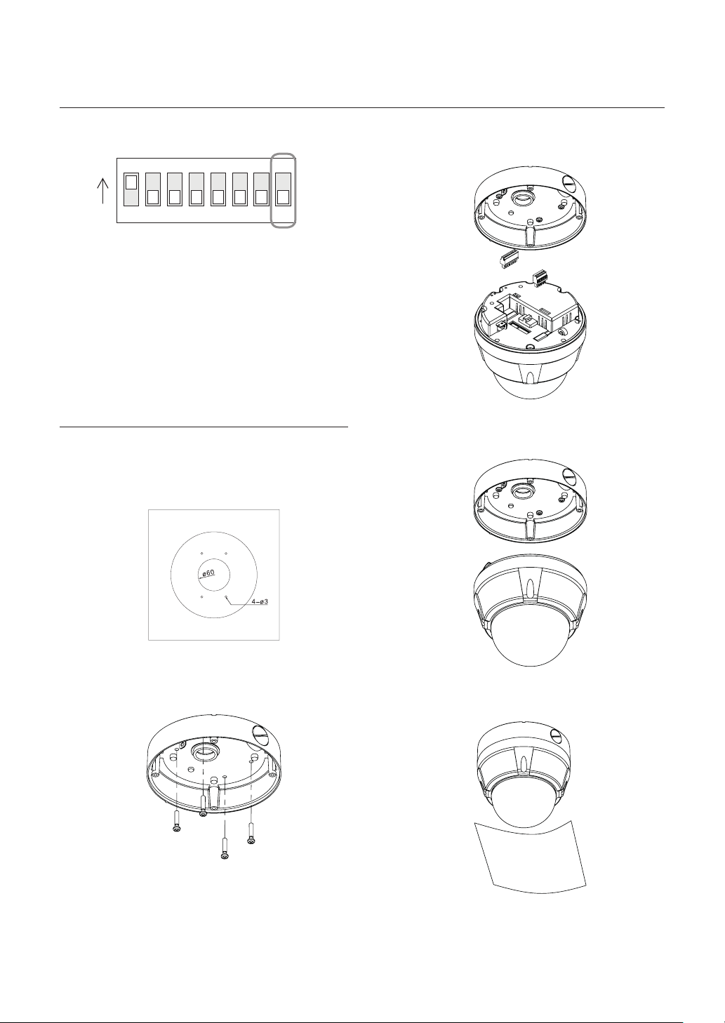
INSTALLATION USING SURFACE
MOUNT ON THE CEILING
SNC-C6225
❖
1. To pass cables to upside of ceiling, please, make
about ø60mm hole on the ceiling panel.
4.
Screw main unit to surface mount bracket with
4 lock-up screws.
2. Screw surface mount bracket to ceiling with
4 screws.
14 – 10x Network Mini Smart Dome Camera
5.
Detach protection vinyl from dome cover.
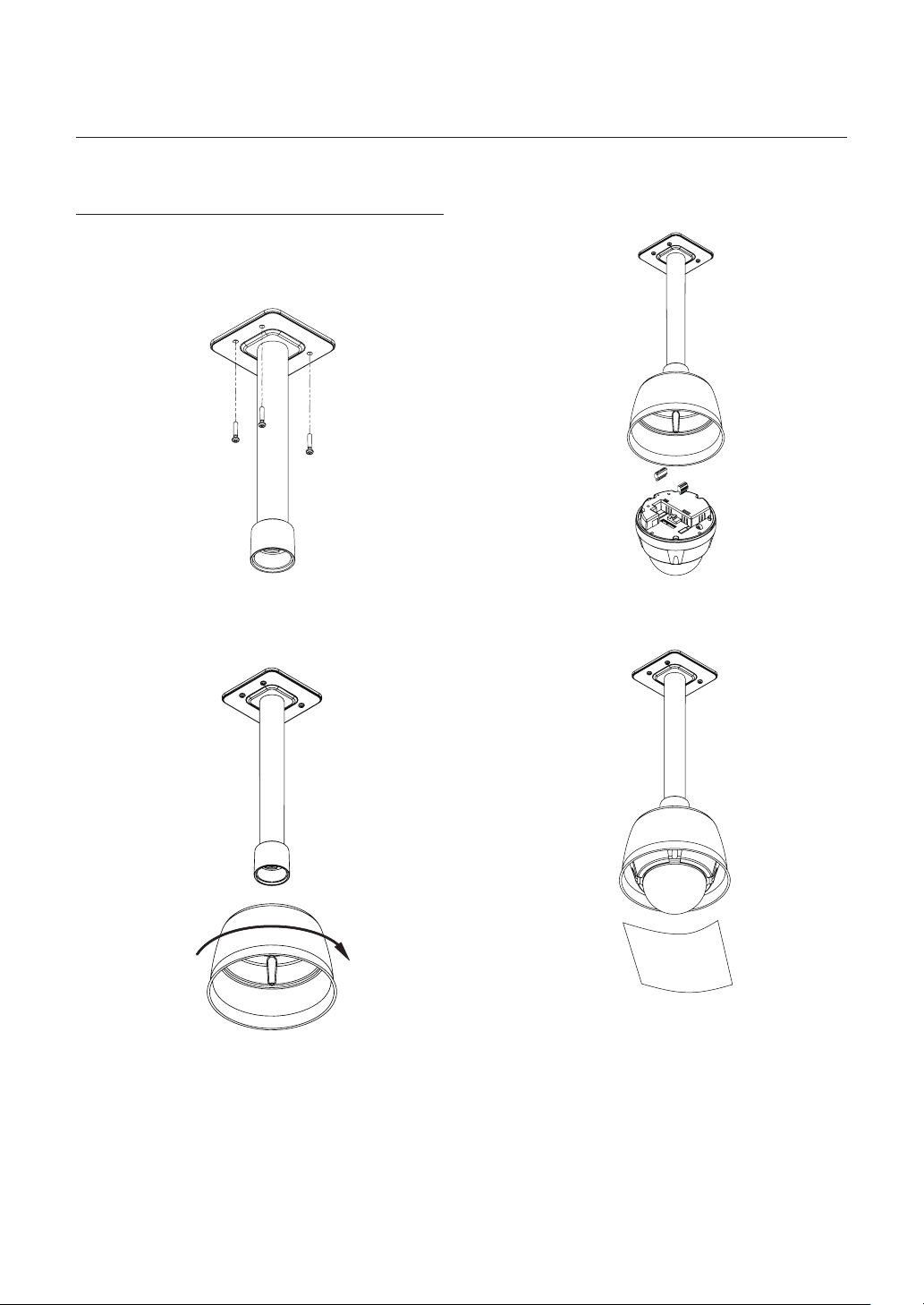
INSTALLATION USING CEILING
MOUNT BRACKET
SNC-C7225
❖
1. Install ceiling mount bracket on the ceiling using
4 screws provided.
installation
3.
After wiring cables to terminals, plug the terminals
into the bottom of main unit. Then, fi x the main
unit with sunshield with 4 screws.
2. Turn sunshield clockwise after locating it in the
pipe head of ceiling mount properly.
4. Detach protection vinyl from dome cover.
English – 15
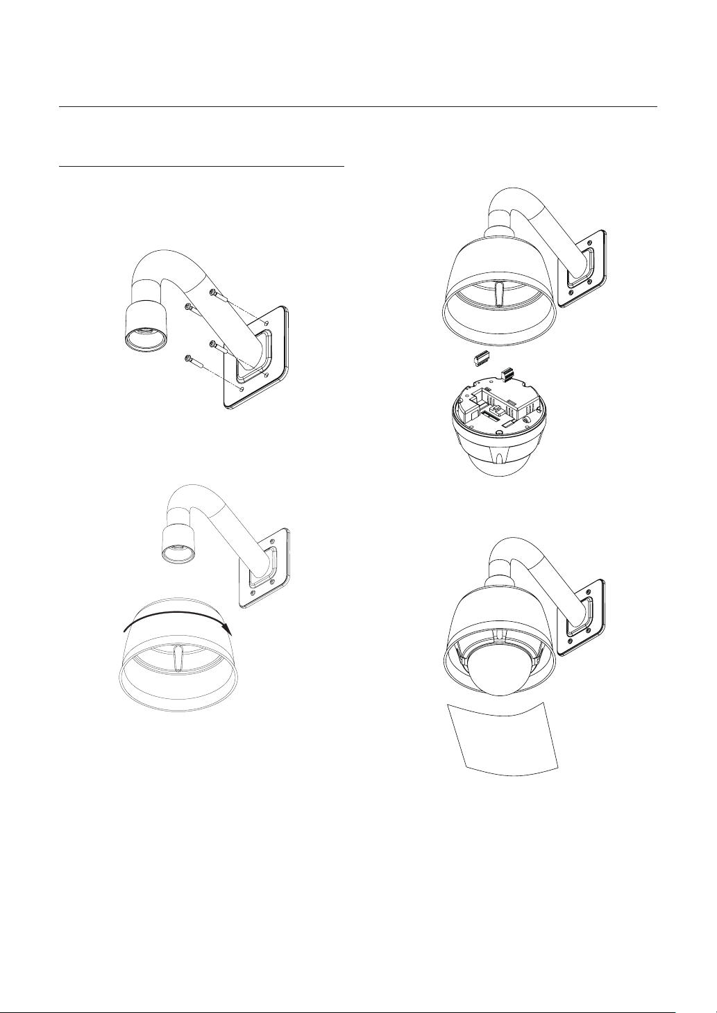
installation
INSTALLATION USING WALL
MOUNT BRACKET
SNC-C7225
❖
1. Use the 4 screws (provided) to secure the wall
mount bracket to the wall.
2. Turn sunshield clockwise after locating it in the
pipe head of wall mount properly.
3. After wiring cables to terminals, plug the terminals
into the bottom of main unit. Then, fi x the main
unit with sunshield with 4 screws.
4. Detach protection vinyl from dome cover.
16 – 10x Network Mini Smart Dome Camera

CABLING
SNC-C6225/SNC-C7225
❖
installation
DC 12V
Controller/DVR
BNC Video
Power Connection
❖
Please, check the voltage and current capacity of rated power carefully.
•
Rated Power Input Voltage Range
Audio In
Audio Out
Power Consumption
SNC-C6225 SNC-C7225
Microphone
Speaker
IrDA
Sensor
Door
Switch
Sensors
Lamp
Relay Out
Network
DC 12V
RS-485 Communication
❖
For PTZ control, connect this line to keyboard and DVR. To control multiple cameras at the same time, RS-485
•
communication lines of them is connected in parallel as shown below.
Keyboard Controller / DVR
RS-485
DC 11V ~ 15V 15W
15W(Heater Off) /
25W(Heater On)
English – 17
installation
Video Connection
❖
Connect with BNC coaxial cable.
•
Audio Input/Ouput Connection
❖
Connect the AUDIO IN port of the camera with the microphone directly or LINE OUT port of the amplifi er that the
1.
microphone is connected to direct Mic Connection: Set Audio Input Gain high (10).
Line Out Connection: Set Audio Input Gain low (1). Refer to page 58 in this Manual.
Connect the AUDIO OUT port of the camera with the LINE IN port of the speaker.
2.
If the microphone is connected directly to AUDIO OUT terminal, the speaker will not produce sound. The MIC IN
function is not supported.
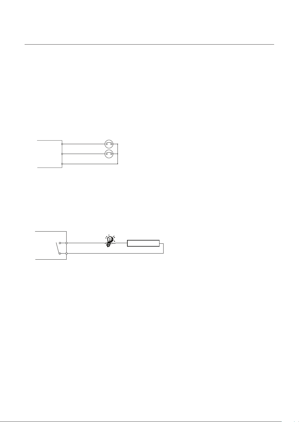
Alarm Input Connection
❖
IN 1
INTERNAL
INTERNAL
Sensor Input
•
It is noted that short circuit between COM and Input pin means alarm activation.
If you want to use Alarm Input, the types of sensor must be selected in SETUP menu. Refer to "ALARM INPUT
SETUP" (Page 64) in this Manual. The sensor types are Normal Open and Normal Close If sensor type is not
selected properly, the alarm can be activated reversely.
IN 1
IN 2
IN 2
IN COM
IN 3
Relay Output
•
Internal
There is 1 Alarm Output and Relay contact type. You do not have to care about polarity, AC/DC, and isolations
between channels. Care must be taken for the power capacity of relay contact written above.
Relay Out
Relay Out
Max DC30V / 1A
AC 125V / 0.5A
Power
18 – 10x Network Mini Smart Dome Camera
installation
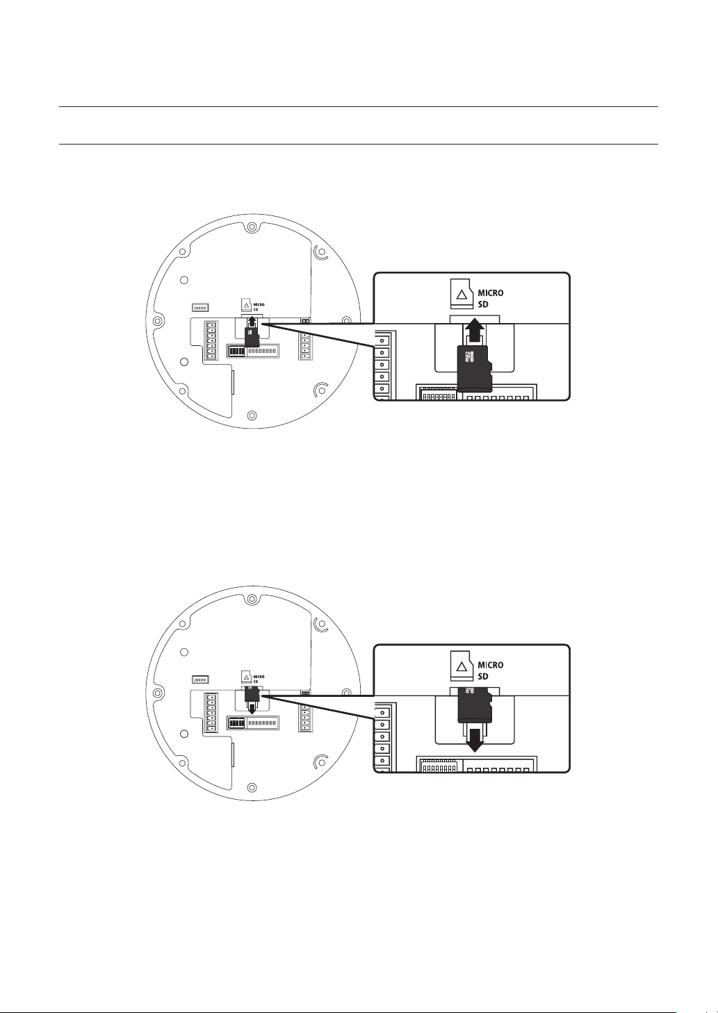
INSERTING/REMOVING AN MICRO SDHC MEMORY CARD
Inserting an Micro SDHC Memory Card
❖
Push the Micro SDHC memory card in the direction of the arrow shown in the diagram.
•
Do not force the memory card in. If you can’t insert the memory card into the slot with ease, you might be inserting the card in
J
the wrong direction. Forcibly inserting a memory card could lead to its damage.
Removing an Micro SDHC Memory Card
❖
Gently press down on the exposed end of the memory card as shown in the diagram to eject the memory card
•
from the slot.
Pressing too hard on the Micro SDHC memory card can cause the card to shoot out uncontrollably from the slot when
J
released.
When removing the Micro SDHC memory card, disable the SD Card Recording feature (refer to page 63 for
•
instructions on disabling SD Card Recording).
Removing the Micro SDHC memory card while recording is in progress can damage the data.
English – 19

installation
MEMORY CARD INFORMATION (NOT INCLUDED)
What is a memory card?
❖
The memory card is an external data storage device that has been developed to offer an entirely new way to record
and share video, audio, and text data using digital devices.
Selecting a memory card that’s suitable for you
❖
Your camera supports Micro SDHC memory cards.
You may, however, experience compatibility issues depending on the model and make of the memory card.
Your camera supports Micro SD memory cards.
However, the maximum supported Micro SD memory card capacity is 2GB and ver 1.1, 4GB or above SD memory
cards are incompatible.
For your camera, we recommend you use a memory card from the following manufacturers:
Micro SDHC/SD Memory Card: Kingston®, Panasonic®, SanDisk®, and Toshiba®
Your camera supports 128MB to 8GB of memory card capacity.
Playback performance can be affected depending on the speed of memory card, so use the high-speed memory
card. To ensure proper recording of video data, we recommend you use a memory card that supports at least read/
write speed 10Mbps and Class 6.
20 – 10x Network Mini Smart Dome Camera

operation
CHECK POINTS BEFORE
OPERATION
Before power is applied, please check the cables
•
carefully.
The camera ID of the controller must be identical to
•
that of the camera to be controlled. The camera ID
can be checked in the System Information of OSD
Menu.
If your controller supports multi-protocols, the protocol
•
must be changed to match to that of the camera.
If you changed camera protocol by changing DIP
•
switch, the change will be effective after you reboot
the camera.
Since the operation method can be different for
•
each controller available, refer to the manual for your
controller if camera can not be controlled properly.
PRESET AND PATTERN
FUNCTION PRE-CHECK
•
Check how to operate Preset, Scan, Auto Pan and
Pattern function with controller or DVR in advance to
operate camera function using them. (refer to your
System keyboard Manual)
•
If controller or DVR has no pattern button or function,
use shortcut keys with preset numbers. For more
information, refer to “Reserved Preset” in this
manual.
AUTO CALIBRATION
•
If the camera is continuously subjected to very high
temperature (over 50°C or 122°F) environment for a
long time, it is possible for the camera to lose focus.
As a result, you will get blurry image. In this case, it
is recommended to turn on “Auto Calibration” by
running Preset 165.
If you execute AUTO CALIBRATION, camera will
•
calibrate its focus at every 6 hours. To turn off this
function, please, run Preset 166.
STARTING OSD MENU
Function
•
Using the OSD menu, Preset, Pattern, Auto Pan,
Scan and Alarm Input function can be confi gured for
each application.
Enter Menu
•
<Go Preset> [95]
RESERVED PRESET
•
Description
Some Preset numbers are reserved for direct access
to specifi c functions in OSD menu. These direct
commands via preset provide quick execution of
various functions using keyboard controller as well as
simplify the interface with DVR and IP equipments.
•
Function
<Go Preset> [95] : Enters into OSD menu
<Go Preset> [131~134] : Runs Pattern Function 1~4
<Go Preset> [141~148] : Runs Auto Pan Function 1~8
<Go Preset> [151~158] : Runs Scan Function 1~8
<Go Preset> [161] : Sets Relay Output to OFF
<Set Preset> [161] : Sets Relay Output to ON
<Go Preset> [165] : Auto Calibration ON.
<Go Preset> [166] : Auto Calibration OFF.
<Go Preset> [167] : Zoom Proportional Jog ON
<Set Preset>[167] : Zoom Proportional Jog OFF
<Go Preset> [170] : Sets Camera BLC Mode to OFF
<Go Preset> [171] : Sets Camera BLC Mode to HIGH
<Go Preset> [174] : Sets Camera Focus Mode to AUTO
<Go Preset> [175] : Sets Camera Focus Mode to Manual
<Go Preset> [176] : Sets Camera Focus Mode to SEMI-
AUTO
<Go Preset> [177] : Sets Day & Night Mode to AUTO1
<Go Preset> [178] : Sets Day & Night Mode to NIGHT
<Go Preset> [179] : Sets Day & Night Mode to DAY
<Go Preset> [190] : Sets OSD Display Mode to AUTO
(Except Privacy Mask)
<Go Preset> [191] : Sets OSD Display Mode to OFF
(Except Privacy Mask)
<Go Preset> [192] : Setting OSD Display Mode to ON
(Except Privacy Mask)
<Go Preset> [193] : Sets all Privacy Mask Display to OFF
<Go Preset> [194] : Sets all Privacy Mask Display to ON
<Go Preset>[200] : Digital Zoom ON
<Go Preset>[201] : Digital Zoom OFF
English – 21
operation
PRESET
Function
•
Max. 127 positions can be stored as Preset position.
The Preset number can be assigned from 1 to 128,
but 95 is reserved for starting OSD menu.
Camera characteristics (i.e. White Balance, Auto
Exposure) can be set up independently for each preset
and they are adjusted by using OSD menu. Four relay
outputs can be reacted in conjunction with one Preset.
Set Preset
•
<Set Preset> [1~128]
Run Preset
•
<Go Preset> [1~128]
Delete Preset
•
To delete Preset, use OSD menu.
Delete Auto Pan
•
To delete Auto Pan, use OSD menu.
PATTERN
•
Function
Pattern Function is that a camera memorizes the path
(mostly curve path) by joystick of controller for assigned
time and revives the path exactly as it memorized.
4 Patterns are available and Maximum 1200
communication commands can be stored in a pattern.
Set Pattern
•
Pattern can be created by one of following two
methods.
Method 1) <Set Pattern> [Pattern NO.]
Pattern editing screen is displayed as bellow.
–
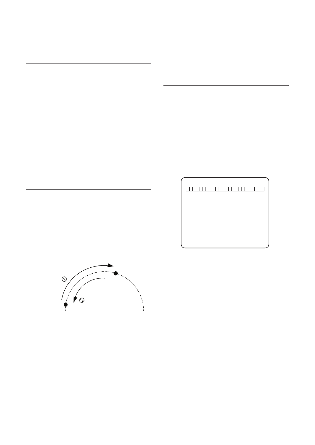
AUTO PAN
Function
•
By using Auto Pan function, you can make camera
to move between 2 Preset positions repeatedly.
When Auto Pan function runs, camera moves from
the preset assigned as the 1st point to the preset
assigned as the 2nd point in CW(Clockwise) direction.
Then camera moves from the preset assigned as the
2nd point to the preset assigned as the 1st point in
CCW(Counterclockwise) direction.
2nd Preset
CW Direction
CCW Direction
1st Preset
In case that the preset assigned as the 1st point
is same as the preset assigned as the 2nd point,
camera turns on its axis by 360° in CW(Clockwise)
direction and then it turns on its axis by 360° in
CCW(Counterclockwise) direction.
Speed can be set up from 1°/sec to 180°/sec.
Set Auto Pan
•
To set Auto Pan, use OSD menu.
•
Run Auto Pan
Method1) <Run Auto Pan> [Auto Pan NO.]
ex) Run Auto Pan 2 : <Run Auto Pan> [2]
Method2) <Go Preset> [Auto Pan NO.+140]
ex) Run Auto Pan 2 : <Go Preset> [142]
EDIT PATTERN 1
[ENTER:SAVE]
Movement by Joystick and preset movement
–
can be memorized in a pattern.
The rest memory size is displayed in progress
–
bar.
To save the recording, press ENTER key.
–
Method 2) OSD Using OSD Menu: See the section
“How to use OSD Menu”.
Run Pattern
•
Method 1) <Run Pattern> [Pattern NO.]
ex) Run Pattern 2 : <Run Pattern> [2]
Method 2) <Go Preset> [Pattern NO.+130]
ex) Run Pattern 2: <Go Preset> [132]
Delete Pattern
•
Use OSD menu to delete a Pattern.
When the PATTERN is saved/executed, the PAN/TILT is
operated with D-FLIP OFF.
0/0/X1/N
22 – 10x Network Mini Smart Dome Camera
operation
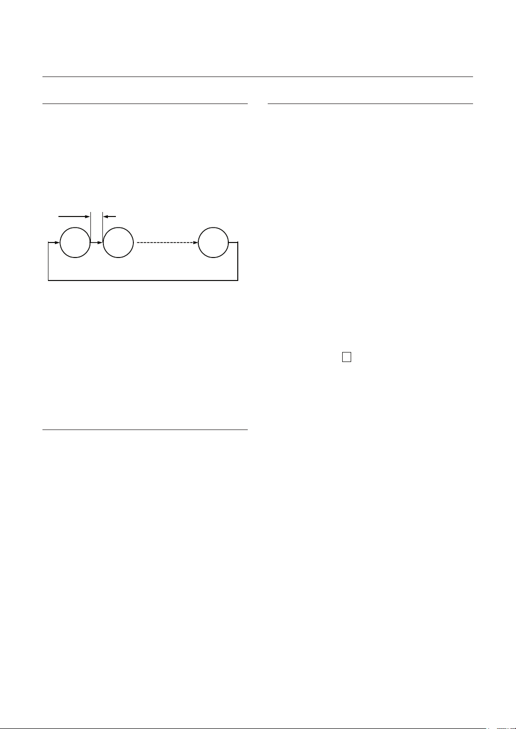
SCAN
Function
•
The Scan function allows running sequence of
Presets, Pattern and/or Auto Pans. Max 8 Scan
can be stored. Each Scan can have max 20 action
entities which can be preset, pattern or Auto Pan.
Preset speed can be set up and the repeat number
of Pattern & Auto Pan can be set up in Scan setup.
Dwell time between actions can be set up also.
Dwell Time
Preset 1
Set Scan
•
Use OSD Menu to create a Scan.
Run Scan
•
Method1) <Run Scan> [Scan NO]
ex) Run Scan 2 : <Run Scan> [2]
Method2) <Go Preset> [Scan NO.+150]
ex) Run Scan 7 : <Go Preset> [157]
Delete Scan
•
Use OSD Menu to delete.
Pattern 1
Max 20 Entities
Scan 1
SCHEDULE
Function
•
The Schedule function allows running an appropriate
function like Preset, Auto Pan, Scan, Pattern, Home
move at designated day and time. For example, if you
setup a rule Tuesday at 9:00AM and Preset 1 (say
Main Gate), the camera will move to main gate every
Tuesday at 9:00AM. If you choose Weekday, camera
will move to Main gate everyday except weekend.
It is noted that due to the real time clock, the time
data will be kept regardless of blackout. The initial
time and day setup is essential to proper Schedule
function.
Set Schedule
•
Use OSD Menu to create a Schedule.
Run Schedule
•
Use OSD Menu of Schedule Master Enable.
•
Delete Schedule
Use OSD Menu to delete.
OTHER FUNCTIONS
Preset Lock
•
This function is made to protect preset data from
unauthorized overwriting. If Preset Lock is ON, Preset
save command using Hot Key is disabled while Preset
save using OSD Menu is acceptable.
Power Up Action
•
This function enables to resume the last action executed
before power down. Most of actions such as Preset,
Pattern, Auto Pan and Scan are available for this function
but Jog actions are not available to resume.
if there are no setup for those functions like
Preset, Pattern, Auto Pan and Scan, Camera will
automatically move to Home position after rebooting.
If Power Up Action is set to be ON, camera will continue
the function which is executed lastly after rebooting.
D-FLIP
•
In case that tilt angle arrives at the top of tilt orbit
(90°), zoom module camera keep moving to opposite
tilt direction (180°) to keep tracing targets. As soon
as zoom module camera passes through the top
of tilt direction (90°), images should be reversed
automatically and F appears in screen. If this function
is set to OFF, tilt movement range is 0 ~ 90°.
Parking Action
•
This function enables to locate the camera to specifi c
position automatically if operator doesn’t operate the
controller for a while. The Park Time can be defi ned as
an interval from 5 seconds to 4 hours.
Alarm Input
•
2 Alarm Inputs are used. If an external sensor
is activated, camera can be set to move to
corresponding preset position. It is noted that the
latest alarm input is effective if multiple sensors are
activated.
Privacy Zone Mask
•
To protect privacy, Max. 4 Privacy Masks can be
created on the arbitrary position to hide objects such
as windows, shops or private house. With Spherical
Coordinates system, powerful Privacy Zone Mask
function is possible.
English – 23
 Loading...