

Page 1

Disassembly and Reassembly
Samsung Electronics
Service Manual
5-1
5
5. Disassembly and Reassembly
5.1 General Precautions on Disassembly
When you disassemble and reassemble components, you must use extreme caution. The close proximity of cables
to moving parts makes proper routing a must.
If components are removed, any cables disturbed by the procedure must be restored as close as possible to their
original positions. Before removing any component from the machine, note the cable routing that will be affected.
Whenever servicing the machine, you
must perform as follows:
1. Check to verify that documents are not stored in
memory .
2. Be sure to remove the toner cartridge before you
disassemble parts.
3. Unplug the power cord.
4. Use a flat and clean surface.
5. Replace only with authorized components.
6. Do not force plastic-material components.
7. Make sure all components are in their proper position.
Releasing Plastic Latches
Many of the parts are held in place with plastic latches.
The latches break easily; release them carefully.
To remove such parts, press the hook end of the latch
away from the part to which it is latched.
Page 2
Samsung Electronics
Service Manual
Disassembly and Reassembly
5-2
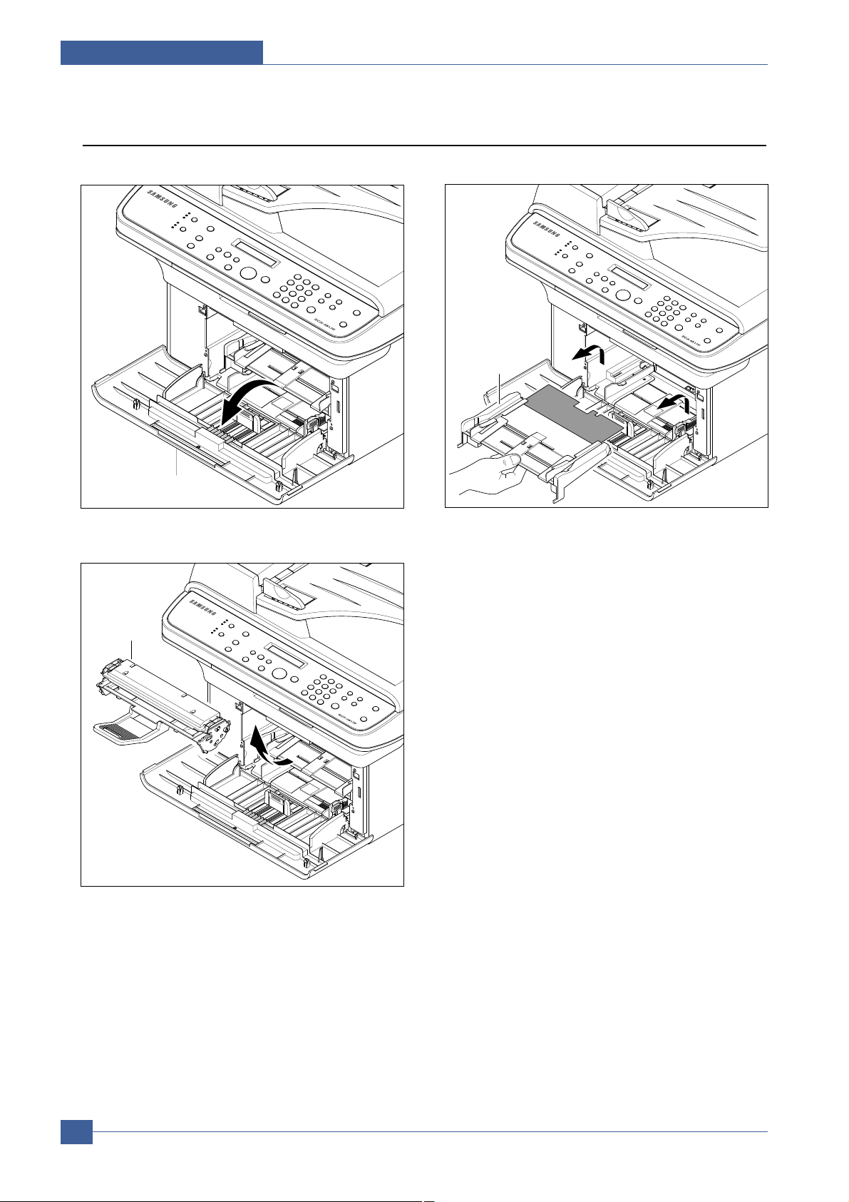
5.2 MP Tray
1. Open the Front Cover.
2. Release the Toner Cartridge.
3. Hold the MP Tray and pull it to the arrow direction.
Front Cover
MP Tray
Toner Cartridge
Page 3
Disassembly and Reassembly
Samsung Electronics
Service Manual
5-3
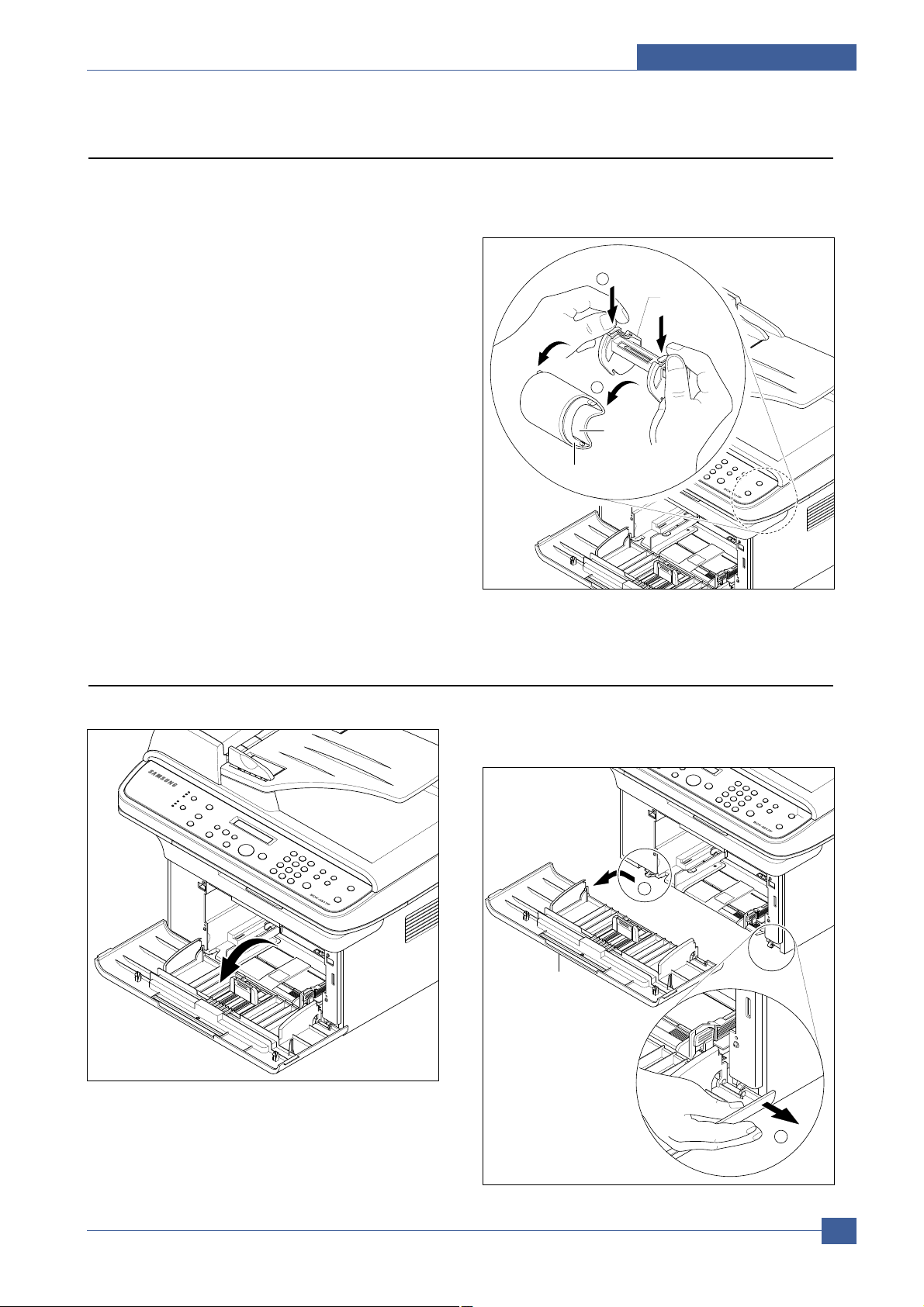
5.3 Pick Up Roller
1. Before you remove the Pick Up Roller, you should
remove:
- MP Tray (Refer to the 5.2)
2. To exchange Pick Up Sponge, pull part Pick Up
Housing U while pressing the hook on the both
side the Pick Up Housing B.
Housing B
2
1
Housing U
Sponge
5.4 Front Cover
1. Open the Front Cover. 2. To remove the Front Cover, first pull the part below
the right side of the Front Cover with a light pressure
to the direction of arrow(left).
Front Cover
2
1
Page 4
Samsung Electronics
Service Manual
Disassembly and Reassembly
5-4
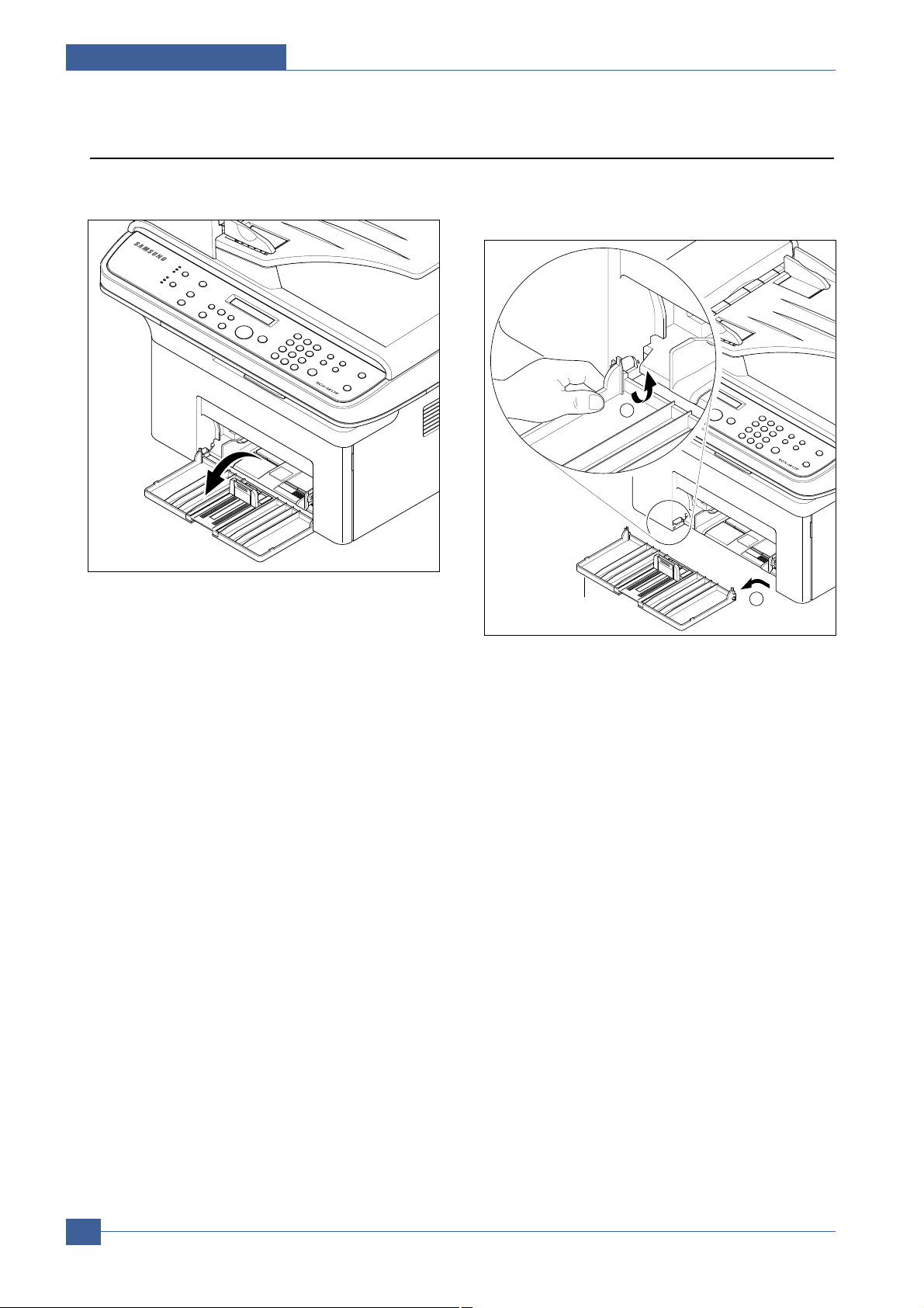
5.5 Cassette Tray
1. Open the Cassette Tray. 2. As shown below, to remove the Cassette Tray, lift
the nob to the direction of the arrow with a light
pressure while holding the Set(left).
1
Cassette Tray
2
Page 5
Disassembly and Reassembly
Samsung Electronics
Service Manual
5-5
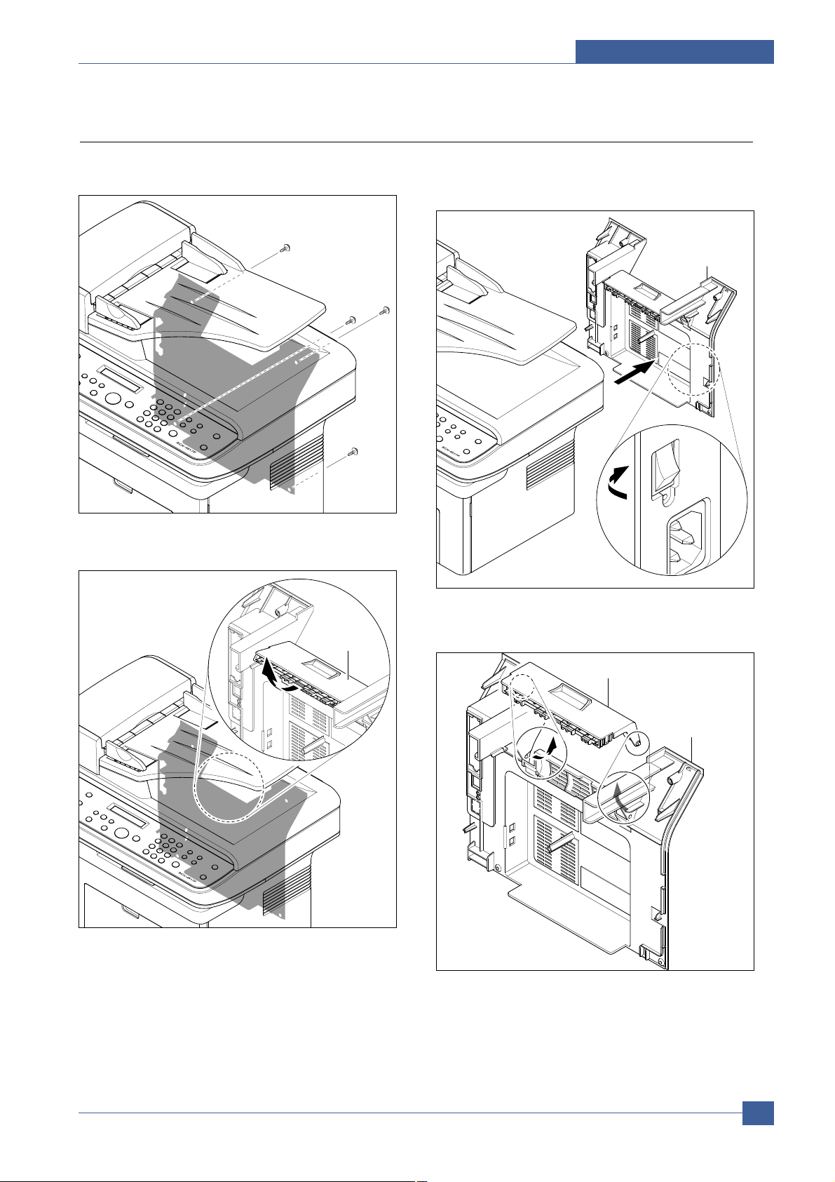
5.6 Rear Cover
1. Remove the four screws securing the Rear Cover
and remove it.
2. Open the Jam Cover.
3. To remove the Rear cover make sure the right
Power Switch doesn't get jammed to the Rear
Cover, as shown below.
4. If necessary, remove the Jam Cover in the direction
of arrow, as shown below.
Rear Cover
Jam Cover
Jam Cover
Rear Cover
Page 6
Samsung Electronics
Service Manual
Disassembly and Reassembly
5-6
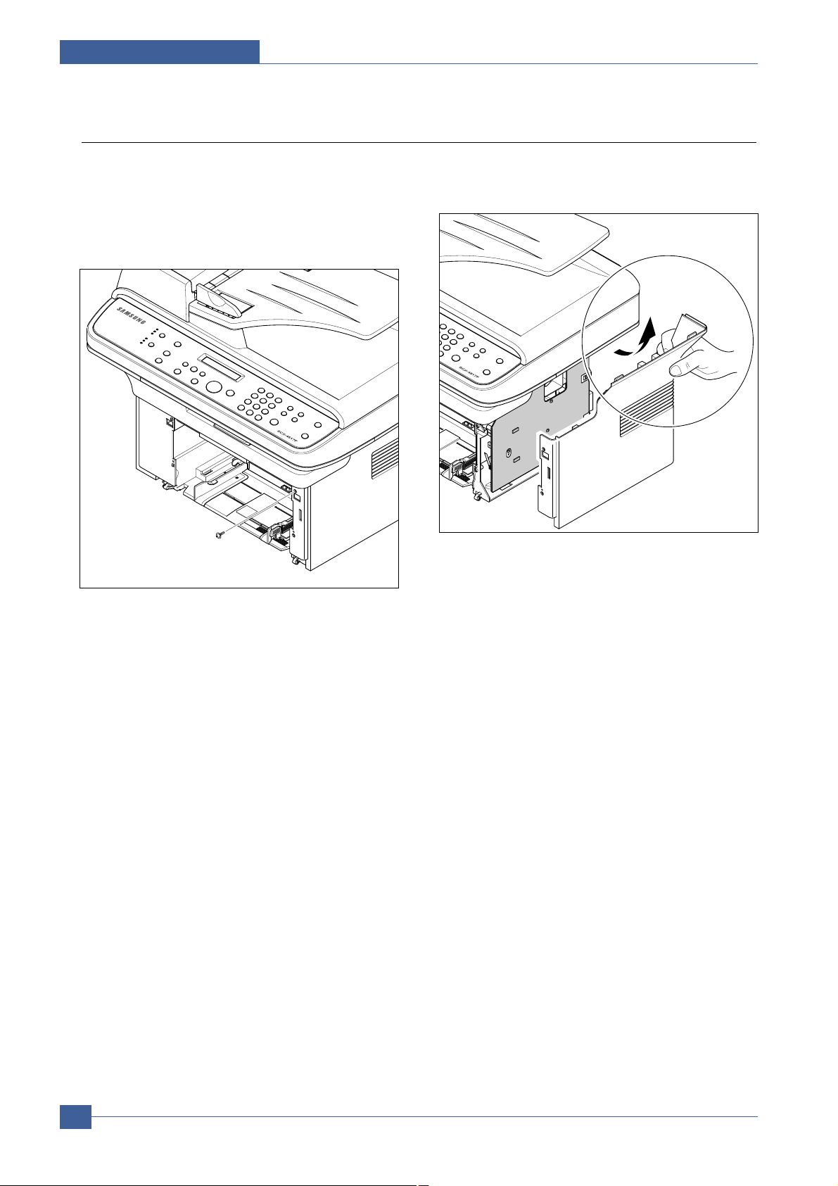
5.7 Right Cover
1. Before you remove the Right Cover, you should
remove:
- Front Cover (Refer to the 5.4)
- Rear Cover (Refer to the 5.6)
2. Remove the one screws securing the Right Cover.
3. Apply light pressure to the back of the Right Cover
and pull it to the right side in the direction of arrow,
as shown below.
Right Cover
Page 7
Disassembly and Reassembly
Samsung Electronics
Service Manual
5-7
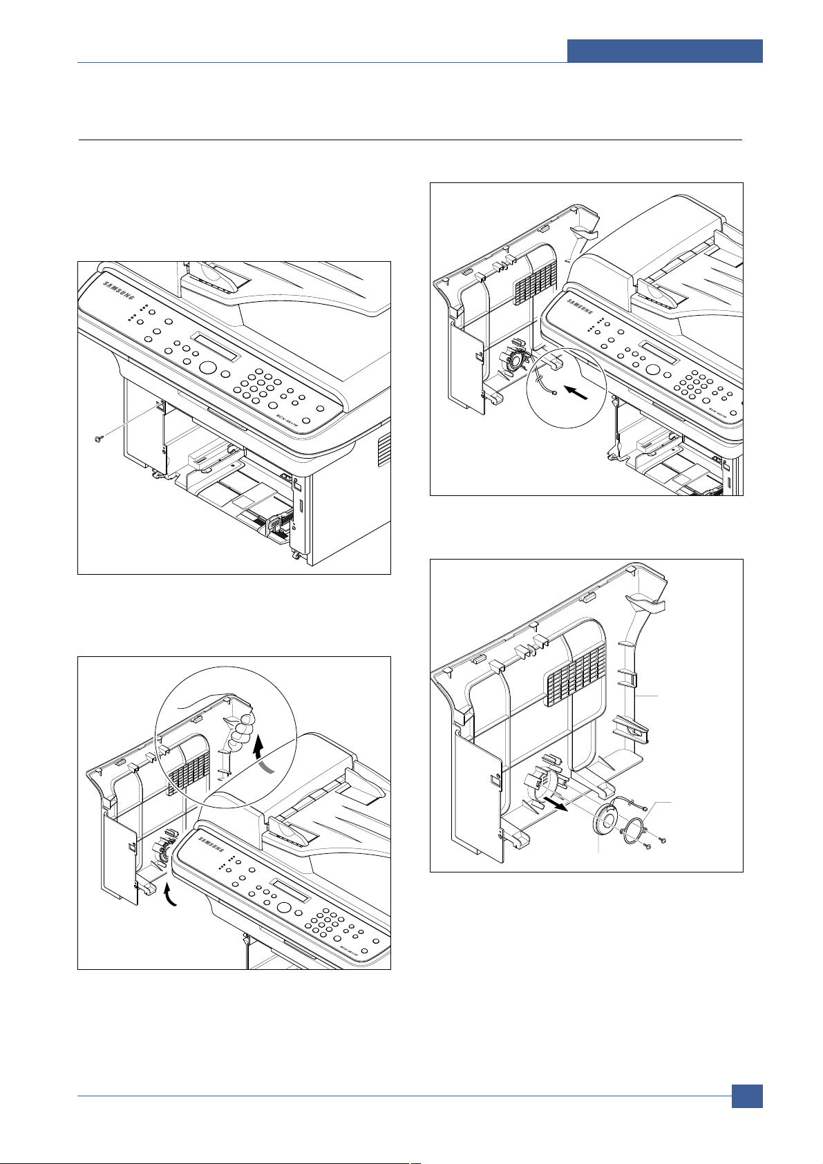
5.8 Left Cover
1. Before you remove the Left Cover, you should
remove:
- Front Cover (Refer to the 5.4)
- Rear Cover (Refer to the 5.6)
2. Remove the one screws securing the Left Cover.
3. Apply light pressure to the back of the Left Cover
and pull it to the leftt side in the direction of arrow,
as shown below.
4. Unplug the Speaker Connector from the Main PBA.
5. If necessary, remove the two screws securing the
Speaker and remove it.
Speaker
Left Cover
Left Cover
Fixing Bracket
Speaker
Page 8

Samsung Electronics
Service Manual
Disassembly and Reassembly
5-8
5.9 Scan Ass'y
1. Before you remove the Scan Ass'y, you should
remove:
- Rear Cover (Refer to the 5.6)
- Right Cover (Refer to the 5.7)
- Left Cover (Refer to the 5.8)
2. Remove the two screws from the Middle Cover and
remove the screw securing the Ground Cable.
3. Unplug the three Connectors(ADF, Scan Motor,
OPE) and Flat Cable-CIS, as shown below.
4. Release the Scan Ass'y in the direction of arrow, as
shown below.
Middle
Cover
Middle
Cover
Scan Ass’y
ADF
Flat
Cable
OPE
Scan
Motor
Page 9

Disassembly and Reassembly
Samsung Electronics
Service Manual
5-9
5.10 ADF Housing
1. Before you remove the ADF Housing, you should
remove:
- Scan Ass'y (Refer to the 5.9)
2. Open the ADF Housing and insurt a flat-blade
screwdriver into the slot as shown below, and
remove the Cap-Hinge from the Platen Housing
and ADF Housing.
3. Remove the ADF Housing from the Platen
Housing. At that time, carefully release the ADF
Motor Harness from the Platen Housing, as shown
below.
4. Remove the two screws securing the ADF Ass'y
and remove it. At that time, carefully release the
ADF Motor Harness from the Platen Cover, as
shown below.
5. If necessary, remove the two screws securing the
TX Stacker Ass'y and remove it, as shown below.
Cap-Hinge
ADF Ass’y
ADF Motor Harness
ADF Housing
Scan Motor
Harness
TX Stacker Ass’y
Platen Cover
Page 10

Samsung Electronics
Service Manual
Disassembly and Reassembly
5-10
6. Open the Open Cover and remove the Open
Cover in the direction of arrow, as shown below.
7. Pull the Bush, then rotate until it reaches the slot,
as shown below. Then lift the Pick Up Unit.
8. Remove the two screws securing the ADF Upper
and insurt a flat-blade screwdriver in to slot as
shown below, and remove the ADF Upper.
9. Unplug the Connector from the ADF PBAand
remove the four screws securing the ADF Motor
Housing and remove it in the direction of arrow, as
shown below.
Open Cover
2
1
2
ADF Upper
ADF Lower
1
ADF Motor Housing
Bush
2
Pick Up Unit
Bearing
Page 11

Disassembly and Reassembly
Samsung Electronics
Service Manual
5-11
5.11 OPE Unit
* Please refer to this procedure when you disassemble
and assemble the SCX-4321.
1. Open the ADF Housing and insurt a flat-blade
screwdriver into the crack as shown below, and
remove the OPE Unit from the Platen Housing.
2. Unplug the three Connectors(Battery, OPE, Full
Sensor), as shown below.
3. Remove the five screws securing the OPE PBA
and remove it.
4. Release the Contact Rubbers, as shown below.
5. Release the Keys, as shown below.
OPE
ADF Housing
2
1
OPE PBA
Rubber-Scroll
Rubber-Tel
Battery
OPE
Full Sensor
OPE PBA
Resolution
Copy
Scroll
OPE Cover
Start
Stop
Tel
FAX
Toner Save
Scan T o
Page 12

Samsung Electronics
Service Manual
Disassembly and Reassembly
5-12
5.12 Platen Housing
1. Before you remove the Platen Housing, you should
remove:
- Scan Ass'y (Refer to the 5.9)
- ADF Housing (Refer to the 5.10)
- OPE Unit (Refer to the 5.11)
2. Remove the five screws from the Scan Upper and
remove it from the Scan Lower, as shown below.
3. Take out the Battery.
4. Push the Holder in the direction of arrow and
remove the Belt, as shown below. (The CIS will
come out at the same time.)
5. Release the Belt and Flat Cable from the CIS.
Scan Upper
Scan Lower
CIS
Belt
3
2
1
Battery
CIS
Belt
Flat Cable
Page 13

Disassembly and Reassembly
Samsung Electronics
Service Manual
5-13
6. Remove the two screws securing the Scan Motor
Ass'y and remove it.
7. If necessary, remove the two screws securing the
Scan Motor and remove it.
8. Using a flat-blade screwdriver remove the Full
Sensor, as shown below.
Scan Motor Ass’y
Full Sensor
Scan Motor
Bracket
Scan Motor
Page 14

Samsung Electronics
Service Manual
Disassembly and Reassembly
5-14
5.13 Middle Cover
1. Before you remove the Middle Cover, you should
remove:
- Scan Ass'y (Refer to the 5.9)
2. Remove the five screws securing the Middle Cover,
as shown below.
3. Carefully release the Middle Cover from the Main
PBA, as shown below.
4. If necessary, take out the Stacker.
Main
PBA
Stacker
Middle Cover
Page 15

Disassembly and Reassembly
Samsung Electronics
Service Manual
5-15
5.14 HVPS
1. Before you remove the HVPS, you should remove:
- Scan Ass'y (Refer to the 5.9)
- Middle Cover (Refer to the 5.13)
2. Remove the three screws securing the Sheet and
remove it.
3. Remove the three screws securing the HVPS and
remove it with the HVPS Ground, as shown below.
4. Unplug the Connector from the HVPS.
HVPS
HVPS Ground
HVPS
Page 16

Samsung Electronics
Service Manual
Disassembly and Reassembly
5-16
5.15 Main PBA
1. Before you remove the Main PBA, you should
remove:
- Scan Ass'y (Refer to the 5.9)
- Middle Cover (Refer to the 5.13)
2. Unplug the all Connectors from the Main PBA, as
shown below.
3. Remove the six screws securing the Main PBA and
remove it.
SMPS/HVPS
Main Motor
LSU
Clutch
LIU
DEVE
Thermister
Main PBA
Page 17

Disassembly and Reassembly
Samsung Electronics
Service Manual
5-17
5.16 RX Drive
1. Before you remove the RX Drive, you should
remove:
- Scan Ass'y (Refer to the 5.9)
- Middle Cover (Refer to the 5.13)
- Main PBA (Refer to the 5.15)
2. If necessary, remove the two Bracket (Port, Main
PBA) and Ground, as shown below.
3. Remove the two screws securing the Engine
Shield and remove the six screws securing the
Frame then remove the RX Drive in the direction of
arrow, as shown below.
4. Remove the Connector, as shown below.
5. Release the four Gears (RDCN, OPC, Fuser, Feed)
from the Frame, as shown below.
6. Remove the four screws securing the Motor
Bracket and remove it. Then remove the two
screws securing the Motor and remove it.
Port Bracket
Ground
Main PBA
Bracket
RX Drive
RDCN Gear
Fuser Gear
OPC DR Gear
Feed Gear
Gear Bracket
RX Motor
Motor Bracket
Page 18

Samsung Electronics
Service Manual
Disassembly and Reassembly
5-18
5.17 Fuser
1. Before you remove the Fuser, you should remove:
- Scan Ass'y (Refer to the 5.9)
- Middle Cover (Refer to the 5.13)
2. Unplug the two Connectors from the SMPS and
Main PBA, as shown below.
3. Remove the four screws securing the Fuser and
remove it, as shown below.
4. Remove the Lever-M-Act Exit in the direction of
arrow, as shown below.
5. Remove the Cover-M-Safty, as shown below.
Thermister
Fuser
Cover-M-Safty
Lever-M-Act Exit
2
1
Fuser
Page 19

Disassembly and Reassembly
Samsung Electronics
Service Manual
5-19
6. Remove the Cover-M-Guide Exit, as shown below.
7. As shown below rotate the Holder to the direction
of the arrow which is attached to the Exit Roller
F/Down and Exit Gear(DRV17). (The Roller_Main,
Roller_FR, F/Down Holder, Spring will come out
at the same time.)
NOTICE: If you don't follow the direction above the
Spring will come out forcing the Roller_Main,
Roller_FR, F/Down Holder inside the Frame
Ass'y .
8. Remove the two screws securing the Thermo Cap
and remove it.
9. Take out the Thermostat then release the CBF
Harness, as shown below.
10. Remove the screw securing the Harness and
remove it. Then take out the Thermistor, as shown
below.
Cover-M-Guide Exit
Exit Gear
Exit Roller F/Down
Thermo Cap
Roller_FR
Roller_Main
F/Down Holder
Holder
Thermostat
Thermistor
Page 20

11. Release the CBF Harness from the Halogen
Lamp and remove the two screws securing the
Halogen Lamp, as shown below.
12. Remove the two screws securing the Cover-M
and remove it.
13. Take out the Halogen Lamp in the direction of
arrow, as shown below.
Samsung Electronics
Service Manual
Disassembly and Reassembly
5-20
Cover-M
Halogen Lamp
Heat Roller
Page 21

Disassembly and Reassembly
Samsung Electronics
Service Manual
5-21
5.18 Engine Shield (LIU PBA, SMPS)
1. Before you remove the Engine Shield, you should
remove:
- Scan Ass'y (Refer to the 5.9)
- Middle Cover (Refer to the 5.13)
2. Unplug the all Connectors from the SMPS and LIU
PBA.
3. Remove the six screws securing the Engine Shield
and release the Harness, as shown below. Then
carefully release the Engine Shield from the
Actuator Feed Sensor Lever.
4. When if only remove the SMPS, first remove the
Rear Cover (refer to the 5.6) and unplug the Fuser
Connector and remove the six screws securing the
SMPS. Then unplug the Connector from the Main
PBA and carefully release the SMPS, as shown
below.
5. When if only remove the LIU PBA, first remove the
Rear Cover (refer to the 5.6) and remove the two
screws securing the LIU PBA. Then unplug the
Connector from the Main PBA and release the LIU
PBA as shown below.
Fuser
LIU Cable
SMPS Cable
Engine Shield
(W/LIU PBA, SMPS)
SMPS
LIU PBA
Actuator Feed Sensor Lever
Page 22

Samsung Electronics
Service Manual
Disassembly and Reassembly
5-22
5.19 LSU
1. Before you remove the LSU, you should remove:
- Scan Ass'y (Refer to the 5.9)
- Middle Cover (Refer to the 5.13)
2. Remove the three screws securing the LSU and
remove it. Then unplug the two Connectors from
the LSU.
LSU
Page 23

Disassembly and Reassembly
Samsung Electronics
Service Manual
5-23
5.20 Paper Path Frame
1. Before you remove the Paper Path Frame, you
should remove:
- Scan Ass'y (Refer to the 5.9)
- Middle Cover (Refer to the 5.13)
- Fuser (Refer to the 5.17)
- Engine Shield (Refer to the 5.18)
2. Remove the four screws securing the Paper Path
Frame and remove it in the direction of arrow, as
shown below.
3. Remove the Transfer Roller from the Frame, as
shown below.
4. Remove the screw securing the Solenoid-MP and
remove it, as shown below.
Solenoid-MP
Paper Path Frame
1
Bush
2
Transfer Roller
Bush(L)
 Loading...