

Page 1

5
5
5-1
Samsung Electronics
Disassembly and Reassembly
Service Manual
5. Disassembly and Reassembly
5.1 General Precautions on Disassembly
When you disassemble and reassemble components, you must use extreme caution. The close
proximity of cables to moving parts makes proper
routing a must.
If components are removed, any cables disturbed
by the procedure must be restored as close as
possible to their original positions. Before removing any component from the machine, note the
cable routing that will be affected.
Whenever servicing the machine, you
must perform as follows:
1. Check to verify that documents are not stored
in memory.
2. Be sure to remove the toner cartridge before
you disassemble parts.
3. Unplug the power cord.
4. Use a flat and clean surface.
5. Replace only with authorized components.
6. Do not force plastic-material components.
7. Make sure all components are in their proper
position.
Releasing Plastic Latches
Many of the parts are held in place with plastic
latches. The latches break easily; release them
carefully.
To remove such parts, press the hook end of the
latch away from the part to which it is latched.
Page 2
5-2
Disassembly and Reassembly
Samsung Electronics
Service Manual
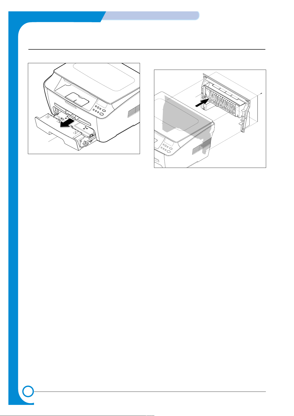
5.2 Front and Rear Cover Units
1. Take the Cassette out of the printer.
2. Remove the Front Cover in the direction of arrow.
3. Remove the 4 screws securing the Rear Cover and
remove it, as shown below.
Cassette
Rear Cover
Page 3

5-3
Samsung Electronics
Disassembly and Reassembly
Service Manual
5.3 Side Covers
1. Before you remove the Side Cover(Left Cover, Right
Cover), you should remove:
-Rear Cover (see page 5-2)
-Front Cover (see page 5-2)
2. Remove 1 screw at the front of the unit. Unclip the
right cover along the top edge and remove it from the
Frame Assembly .
3. Remove 1 screw at the front of the unit. Unclip the
right cover along the top edge and remove it from the
Frame Assembly .
Right Cover
Left Cover
Page 4

5-4
Disassembly and Reassembly
Samsung Electronics
Service Manual
5.4.1 Remove Scanner Ass’y
1. Before you remove the Scanner Ass'y, you should
remove:
-Rear Cover (see page 5-2)
-Side Cover(Left Cover, Right Cover)(see page 5-3)
2. Remove the 2 connectors from the main PBAand
release the ground wire from the Motor Drive Ass’y as
shown below.
3. Carefully lift the Scanner Ass’y from the base taking
care to thread the cables through the frame.
5.4 Scanner Ass’y
< Caution >
1. Before disassembling the Scanner Ass'y first lift
it carefully at the front edge. The support lever
will automatically raise into position.
2. Take care not to trap your fingers or hand in the
mechanism.
Scanner Ass’y
Page 5

5-5
Samsung Electronics
Disassembly and Reassembly
Service Manual
5.4.2 Dismantle Scanner Ass’y
1. Lift the Platen Cover upward and remove it.
2. Release 8 clips (2 per side) securing the scanner
upper frame to the scanner lower frame and remove
the upper frame
3. Remove the CCD Cable, as shown below.
Platen Cover
< Caution >
1. Before disassembling the scanner module
remove the 2 plastic spacers from each end of
the scanner module.
SLIDE CIS
Scan Upper
FFC Cable
Page 6

5-6
Disassembly and Reassembly
Samsung Electronics
Service Manual
4. Pull up the CCD Shaft and take out the Scanner
Module.
5. Push the Belt Holder and take out the Belt, as shown
below.
6. Remove the Pulley Idle, as shown below.
7. Remove the 2 screws and take out the Scan Motor
Ass'y .
Belt
Scanner Module
CIS Shaft
Spring
Pulley Idle
ETC Belt
Pulley Bracket
Scan Motor
Ass’y
Page 7

5-7
Samsung Electronics
Disassembly and Reassembly
Service Manual
5.5 Middle Cover
1. Disconnect the OPE harness from the Main PBAand
remove the 4 screws securing the Middle Cover.
Remove it, as shown below.
2. Remove the 4 screws securing the OPE Unit from the
Middle Cover.
Middle Cover
OPE Harness
OPE Unit
Page 8

5-8
Disassembly and Reassembly
Samsung Electronics
Service Manual
1. Before you remove the Fuser, you should remove:
-Rear Cover (see page 5-2)
2. Unplug two connectors from the boards and then
remove 4 screws. Remove the Fuser Ass’y taking
care not to damage the Exit Sensor.
3. Remove 2 screws and take the Thermostat out of the
Fuser.
4. Remove 2 screws and take the Halogen Lamp out of
the Heat Roller.
5.Remove 1 screw and take the Idle Gear out.
Fuser Ass’y
5.6 Fuser(Heat Lamp Type)
Heat Roller
Halogen Lamp
Idle Gear
Thermostat
Page 9

5-9
Samsung Electronics
Disassembly and Reassembly
Service Manual
6. Remove 4 screws and divide the Fuser into two parts.
7. Unwrap the Thermistor Harness, as shown below.
8. Remove the Thermister from the Fuser Cover.
Fuser Cover
Thermister Harness
Thermister
Page 10

5-10
Disassembly and Reassembly
Samsung Electronics
Service Manual
5.7 Exit Roller
1. Before you remove the Exit Roller you should remove:
- Rear Cover (see page 5-2)
- Side Covers (see page 5-3)
- Scanner Ass’y (see page 5-4)
- Middle Cover (see page 5-6)
2. Remove the white Exit Gear, and release a bearing
clip at one end then remove the shaft and rollers as
shown below.
Exit Gear
Bearing
Exit Roller
1
2
5.8 LSU
1. Before you remove the LSU you should remove:
- Rear Cover (see page 5-2)
- Side Covers (see page 5-3)
- Scanner Ass’y (see page 5-4)
- Middle Cover (see page 5-6)
2. Unplug 2 connector from the LSU.
3. Unplug 4 screws and take the LSU out.
LSU
Page 11

5-11
Samsung Electronics
Disassembly and Reassembly
Service Manual
5.9 Fan
1. Before you remove the Fan you should remove:
- Rear Cover (see page 5-2)
- Right Side Cover (see page 5-3)
2. Unplug the connector from the SMPS and remove 1
screw. Then take out the Fan.
DC Fan
5.10 Drive Ass’y
1. Before you remove the Drive Ass’y, you should
remove:
- Rear Cover (see page 5-2)
- Left Side Cover (see page 5-3)
2. Remove the 6 screws from the Drive Ass’y.
Note when re-fitting the motor Drive Ass’y tighten the
screws in the order that they are numbered on the Motor
Drive Ass’y base plate.
3. Unplug 1 connector from the Drive Ass'y.
Drive Ass’y
Page 12

5-12
Disassembly and Reassembly
Samsung Electronics
Service Manual
5.11 Engine Shield Ass’y
1. Before you remove the Fuser, you should remove:
- Rear Cover (see page 5-2)
- Side Covers (see page 5-3)
- Fuser Connector (see page 5-7)
2. Remove the 14 screws securing the Engine Shield
Ass'y and unplug the all connectors. Then remove the
Engine Shield Ass'y.
Engine Shield
Ass’y
5.12 Main PBA
1. Before you remove the Main PBA, you should
remove:
- Rear Cover (see page 5-2)
- Side Covers (see page 5-3)
- Fuser Connector (see page 5-7)
- Engine Shield Ass'y (see page 5-11)
2. Unplug 1 connector and remove 5 screws from the
Main PBA. Then lift the Main PBAout as shown
below.
Main PBA
Page 13

5-13
Samsung Electronics
Disassembly and Reassembly
Service Manual
5.13 SMPS
1. Before you remove the SMPS, you should remove:
- Rear Cover (see page 5-2)
- Side Covers (see page 5-3)
- Fuser Connector (see page 5-7)
- Engine Shield Ass'y (see page 5-11)
2. Unplug 1 connector and remove 3 screws then take
the Inlet Bracket out.
3. Remove 1 screw and unplug 1 connector from the
Main PBA.
4. Remove 3 screws and take the SMPS out.
SMPS
Inlet Bracket
Page 14

5-14
Disassembly and Reassembly
Samsung Electronics
Service Manual
5.14 Transfer Roller
1. Before you remove the Transfer Roller you should
remove:
- Rear Cover (see page 5-2)
- Side Covers (see page 5-3)
- Scanner Ass’y (see page 5-4)
- Middle Cover (see page 5-6)
- LSU(see page 5-9)
2. Remove 3 screws and take the Transfer Earth out.
3. Unplug the PTL Holder Connector then remove the
PTL Holder and PTL Lens as shown below. Take care
to note the orientation of the PTL lens and ensure it is
refitted correctly
4. Unlatch the Bush and remove it. Then lift the Transfer
Roller out, as shown below.
Transfer
Roller
Bush
Transfer
Earth
PTL
Holder
PTL
Lens
Page 15

5-15
Samsung Electronics
Disassembly and Reassembly
Service Manual
5.15 Feed Roller
1. Before you remove the Feed Roller you should
remove:
- Rear Cover (see page 5-2)
- Side Covers (see page 5-3)
- Scanner Ass’y (see page 5-4)
- Middle Cover (see page 5-6)
- LSU (see page 5-9)
- Drive Ass’y (see page 5-10)
2. Remove 2 screws from the Guide Paper and take it out.
3. Pull up the Feed Idle Bush and Feed Idle Shaft, as
shown below.
4. Remove 3 screws from the Feed Bracket and take it out.
5. Remove the Idle Gear and Feed Gear2.
6. Remove the Feed Gear 1 Ass’y, as shown below.
Feed Bracket
Guide
Paper
Feed Gear2
Bush
Feed Idle
Shaft
Idle Gear
Feed Gear1
Ass’y
Page 16

5-16
Disassembly and Reassembly
Samsung Electronics
Service Manual
7. Remove the Feed Roller and Feed Roller1, as shown
below.
Feed Roller1
Feed Roller
Page 17

5-17
Samsung Electronics
Disassembly and Reassembly
Service Manual
5.16 Pick Up Roller & Solenoid
1. Before you remove the Pick Up Roller and Solenoid
you should remove:
- Rear Cover (see page 5-2)
- Side Covers (see page 5-3)
- Scanner Ass’y (see page 5-4)
- Middle Cover (see page 5-6)
- LSU (see page 5-9)
- Drive Ass’y (see page 5-10)
- Feed Bracket and Gears (See page 5-14 steps 4 - 6)
2. Remove the Pick up Gear Ass’y, as shown below.
3. Remove the Pick up Ass’y, as shown below.
4. Remove 2 screws then remove the Regi Solenoid and
Pick Up Solenoid.
(Pick up)
Solenoid
(Regi)
Solenoid
Pick up Gear
Ass’y
Bush
1
2
Pick up Ass’y
Page 18

5-18
Disassembly and Reassembly
Samsung Electronics
Service Manual
MEMO
 Loading...