

Samsung ML-1740 Service Manual

SERVICE
LASER PRINTER
ML-1740
Manual
LASER PRINTER CONTENTS
1. Precautions
2. Reference Information
3. Specifications
4. Summary of product
5. Disassembly and Reassembly
6. Alignment and Adjustments
7. Troubleshooting
8. Exploded Views and Parts List
9. Block Diagram
10. Connection Diagram

© Samsung Electronics Co.,Ltd. December 2003
Printed in Korea.
VERSION NO. : 1.00 CODE : JC-0117A
This service manual is also provided on the web,
the ITSELF system f Samsung Electronics Co., Ltd.
http://itself.sec.samsung.co.kr
ELECTRONICS
2003. 12

1
1
1-1
Samsung Electronics
Precautions
Service Manual
1. Precautions
The cautions in the below are items needed to keep in mind when maintaining and servicing.
Please read carefully and keep the contents in mind to prevent accidents while servicing and to prevent
that the machine gets damage.
1.1 Warning for safety.
(1) Request the service by qualified service person.
The service for this machine must be performed by a service person who took the additional education of
this field.
It is dangerous if unqualified service person or user tries to fix the machine.
(2) Do not rebuild it discretionary.
Do not attach or change pats discretionary. Do not dissemble, fix, and rebuilt it. If do, printer will abnormally
work and electric shock or a fire can be occurred.
(3) Laser Safety Statement
The Printer is certified in the U.S. to conform to the requirements of DHHS 21 CFR, chapter 1 Subchapter J
for Class 1(1) laser products, and elsewhere, is certified as a Class I laser product conforming to the
requirements of IEC 825.
Class I laser products are not considered to be hazardous. The laser system and printer are designed so
there is never any human access to laser radiation above a Class I level during normal operation, user
maintenance, or prescribed service condition.
Warning >> Never operate or service the printer with the protective cover removed from Laser/Scanner assembly. The reflected
beam, although invisible, can damage your eyes. When using this product, these basic safety precautions should
always be followed to reduce risk of fire, electric shock, and injury to persons.
CAUTION - INVISIBLE LASER RADIATION
WHEN THIS COVER OPEN.
DO NOT OPEN THIS COVER.
VORSICHT - UNSICHTBARE LASERSTRAHLUNG,
WENN ABDECKUNG GE FFNET.
NICHT DEM STRAHL AUSSETZEN.
ATTENTION - RAYONNEMENT LASER INVISIBLE EN CAS
D OUVERTURE. EXPOSITION DANGEREUSE
AU FAISCEAU.
ATTENZIONE - RADIAZIONE LASER INVISIBILE IN CASO DI
APERTURA. EVITARE LESPOSIZIONE AL
FASCIO.
PRECAUCION - RADIACION LASER IVISIBLE CUANDO SE ABRE.
EVITAR EXPONERSE AL RAYO.
ADVARSEL. - USYNLIG LASERSTR LNING VED BNING, N R
SIKKERHEDSBRYDERE ER UDE AF FUNKTION.
UNDG UDSAETTELSE FOR STR LNING.
ADVARSEL. - USYNLIG LASERSTR LNING N R DEKSEL
PNES. STIRR IKKE INN I STR LEN.
UNNG EKSPONERING FOR STR LEN.
VARNING - OSYNLIG LASERSTR LNING N R DENNA DEL
R PPNAD OCH SP RREN R URKOPPLAD.
BETRAKTA EJ STR LEN. STR LEN R FARLIG.
VARO! - AVATTAESSA JA SUOJALUKITUS OHITETTAESSA
OLET ALTTIINA N KYM TT M LLE LASERS TEILYLLE L KATSO S TEESEEN.

1-2
Precautions
Samsung Electronics
Service Manual
1.2 Caution for safety
1.2.1 Precaution related noxious material
The toner in a printer cartridge contains a chemical material, which might harm human body if it is swallowed.
Please keep children out of the toner cartridge.
1.2.2 Precaution related electric shock or fire
It is possible to get electric shock or burn by fire if you don't fallow the instructions of the manual.
(1) Use exact voltage. Please do use an exact voltage and wall socket. If not, a fire or an electric leakage can
be caused.
(2) Use authorized power code. Do use the power code supplied with PRINTER. Afire can be occurred when
over current flows in the power code.
(3) Do not insert many codes in an outlet. If do, a fire can be occurred due to flow over current in an outlet.
(4) Do not put water or extraneous matter in the PRINTER. Please do not put water, other liquid, pin, clip, etc.
It can cause a fire, electric shock, or malfunction. If it is happened, turn off the power and remove the
power plug from outlet immediately.
(5) Do not touch the power plug with wet hand. When servicing, do remove the power plug from outlet. And
do not insert or take off it with wet hand. Electric shock can be occurred.
(6) Caution when inserting or taking off the power plug. The power plug has to be inserted completely. If not,
a fire can be caused due to poor contact. When taking off the power plug, do grip the plug and take it off.
If grip the line and pull over, it could be damaged. A fire or electric shock could cause.
(7) Management of power code. Do not bend, twist, or bind it and place other materials on it. Also, do not fix
it with staples. If the power code gets damage, a fire or electric shock can be caused. Adamaged power
code must be replaced immediately . Do not repair the damaged part and reuse it. Arepaired part with plas-
tic tape can be occurred a fire or electric shock. Do not spread chemicals on the power code. Do not
spread insecticide on the power code. Afire or electric shock can be occurred due to thinner(weak) cover
of the power code.
(8) Check whether the power outlet and the power plug are damaged, pressed, chopped, or blazing fire or
not. When such inferiorities are found, repair it immediately. Do not make it pressed or chopped when
moving the machine.
(9) Caution when thundering, and being flash of lightening. It causes a fire or electric shock. Take the power
plug off when thundering. Do not touch cable and device when thundering and being flash of lightening.
(10) Do avoid the place where is moisture or has dust. Do not install the printer in where have lots of dust or
around humidifier. A fire can be occurred. Aplug part need to clean well with dried fabric to remove dust.
If water drops are dripped on the place covered with dust, a fire can be occurred.
(11) Avoid direct sunlight. Do not install the printer near to window where directly contacts to the sunlight. If
the machine contacts sunlight long time, the machine cannot work properly because inner temperature
of the machine is getting higher. A fire can be caused.
(12) Turn off the power and take off the plug when a smoke, strange smell, or sound from the machine. If you
keep using it, a fire can be occurred.
(13) Do not insert steel or metal piece inside/outside of the machine. Do not put steel or metal piece into a
ventilator. An electric shock could be happened.

1-3
Samsung Electronics
Precautions
Service Manual
1.2.3 Precaution related handling the machine.
If you ignore this information, you could get harm and machine could be damaged.
(1) Do not install it on the different levels, or slanted floor.
Please confirm whether it is balanced or not after installation. If it is unbalanced, an accident can be happened due to the machine fell over.
(2) Be careful not to insert a finger or hair in the rotating unit.
Be careful not to insert a finger of hair in the rotating unit (motor, fan, paper feeding part, etc) while the
machine is operating. Once it happens, you could harm.
(3) Do not place a pot contains water/chemical or small metals. If those are got into the inner side of machine,
a fire or electric shock can be occurred.
(4) Do not install it in where lots of moisture or dust exists or where raindrop reaches. Afire or electric shock
can be caused.
(5) Do not place a candlelight, burning cigarette, and etc. on the machine. Do not install it near to heater. A
fire can be occurred.
1.2.4 Precaution when assembly/disassembly
When replace parts, do it very carefully. Do memorize the location of each cable before replace parts for
reconnecting it afterwards. Do memorize. Please perform the below before replace or disassembly the parts.
(1) Check the contents stored in the memory. All the information will be erased after replace main board. The
information needed to keep has to be written down.
(2) Before servicing or replacing electric parts, take off a plug.
(3) Take off printer cables and power code connected to printer.
(4) Do use formal parts and same standardized goods when
replacing parts.Must check the product name, part code,
rated voltage, rated current, operating temperature, etc.
(5) Do not give an over-force when release or tighten up the
plastic parts.
(6) Be careful not to drop the small parts such as screws in the
printer.
(7) Be careful not to change the location of small parts such as
screws when assembling and disassembling.
(8) Do remove dust or foreign matters completely to prevent fire
of tracking, short, or etc.
(9) After finished repair, check the assembling state whether it is
same as before the repair or not.
552 mm(21.7 in.)
100 mm
(3.9 in.)
954.6 mm(37.5 in.)
482.6 mm(18.8 in.)
100 mm
(3.9 in.)
100 mm
(3.9 in.)
<Installation space>

1-4
Precautions
Samsung Electronics
Service Manual
1.3 ESD Precautions
Certain semiconductor devices can be easily damaged by static electricity. Such components are commonly
called “Electrostatically Sensitive (ES) Devices”, or ESDs. Examples of typical ESDs are: integrated circuits,
some field effect transistors, and semiconductor “chip” components.
The techniques outlined below should be followed to help reduce the incidence of component damage caused
by static electricity.
Caution >>Be sure no power is applied to the chassis or circuit, and observe all other safety precautions.
1. Immediately before handling a semiconductor component or semiconductor-equipped assembly, drain off
any electrostatic charge on your body by touching a known earth ground. Alternatively, employ a commercially available wrist strap device, which should be removed for your personal safety reasons prior to applying power to the unit under test.
2. After removing an electrical assembly equipped with ESDs, place the assembly on a conductive surface,
such as aluminum or copper foil, or conductive foam, to prevent electrostatic charge buildup in the vicinity
of the assembly.
3. Use only a grounded tip soldering iron to solder or desolder ESDs.
4. Use only an “anti-static” solder removal device. Some solder removal devices not classified as “anti-static”
can generate electrical charges sufficient to damage ESDs.
5. Do not use Freon-propelled chemicals. When sprayed, these can generate electrical charges sufficient to
damage ESDs.
6. Do not remove a replacement ESD from its protective packaging until immediately before installing it. Most
replacement ESDs are packaged with all leads shorted together by conductive foam, aluminum foil, or a
comparable conductive material.
7. Immediately before removing the protective shorting material from the leads of a replacement ESD, touch
the protective material to the chassis or circuit assembly into which the device will be installed.
8. Maintain continuous electrical contact between the ESD and the assembly into which it will be installed,
until completely plugged or soldered into the circuit.
9. Minimize bodily motions when handling unpackaged replacement ESDs. Normal motions, such as the
brushing together of clothing fabric and lifting one’s foot from a carpeted floor, can generate static electricity sufficient to damage an ESD.
2
2
2-1
Samsung Electronics
REFERENCE INFORMATION
Service Manual
2. Reference Information
This chapter describes the reference information for applying this training manual, and it is consisted of the tool list, the abbreviation table, the outline of model, and so on.
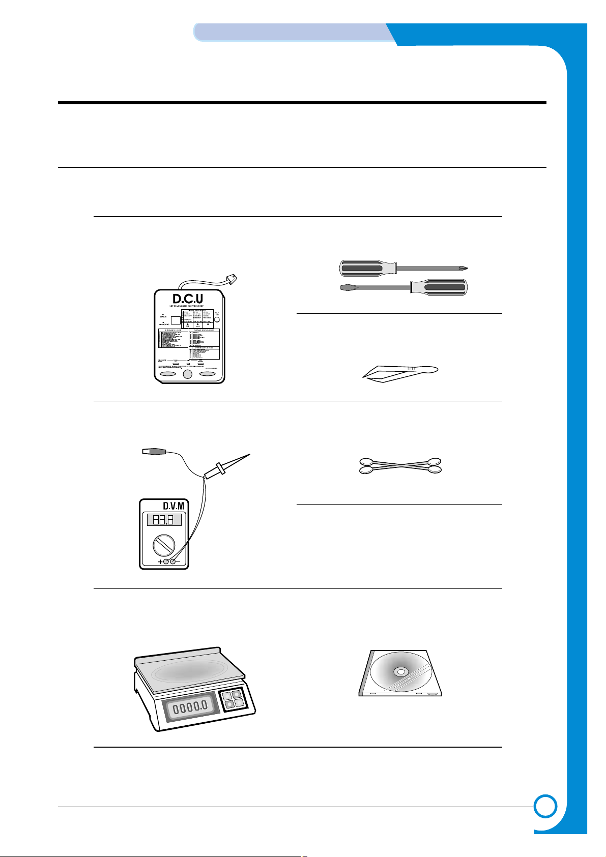
2.1 Tool for Troubleshooting
The following tools are recommended for safe and smooth troubleshooting described in this service manual.
DCU(Diagnostic Control Unit)
Standard : Test equipment to diagnose the Laser
printer supplied by Samsung Electronics.
1
Driver
Standard : "-" type, "+" type (M3 long, M3 short, M2 long,
M2 short).
4
Cotton Swab
Standard : For general home use, for medical ser-vice
6
Software(Driver) installation CD ROM
8
Cleaning Equipments a IPA(Isopropyl
Alcohol)dry cloth or a soft stuff neutral
detergent
7
T weezers
Standard : For general home use, small type.
5
DVM(Digital Volt Meter)
Standard : Indicates more than 3 digits.
2
Electronic Scale
Standard : Equipment to check the weight of consumables(toner cartridge) supplied by Samsung
Electronics. (The gram unit can be measured.)
3
2-2
REFERENCE INFORMATION
Samsung Electronics
Service Manual
2.2 Acronyms and Abbreviations
The table in the below explains abbreviations used in this service manual.
The contents of this service manual are declared with abbreviations in many parts. Please refer to the
table.
AC Alternating Current
ASIC Application Specific Integrated Circuit
ASSY assembly
BIOS Basic Input Output System
CMOS Complementary Metal Oxide
Semiconductor
CN connector
CON connector
CPU Central Processing Unit
dB decibel
dbA decibelampere
dBM decibel milliwatt
DC direct current
DCU Diagnostic Control Unit
DPI Dot Per Inch
DRAM Dynamic Random Access Memory
DVM Digital Voltmeter
ECP Enhanced Capability Port
EEPROM Electronically Erasable Programmable
Read Only Memory
EMI Electro Magnetic Interference
EP electrophotographic
EPP Enhanced Parallel Port
F/W firmware
GDI graphics device interface
GND ground
HBP Host Based Printing
HDD Hard Disk Drive
HV high voltage
HVPS High Voltage Power Supply
I/F interface
I/O Input and Output
IC integrated circuit
IDE Intelligent Drive electronics or Imbedded
Drive Electronics
IEEE Institute of Electrical and Electronics
Engineers. Inc
IPA Isopropy Alcohol
IPM Images Per Minute
LAN local area network
lb pound(s)
LBP Laser Beam Printer
LCD Liquid Crystal Display
LED Light Emitting Diode
LSU Laser Scanning Unit
MB megabyte
MHz megahertz
NVRAM nonvolatile random access memory
OPC Organic Photo Conductor
PBA Printed Board Assembly
PCL Printer Command Language , Printer
Control Language
PDL Page Discription Language
PPM Page Per Minute
PTL Pre-Transfer Lamp
Q-PID Quick Printer Initiating Device
Q ty quantity
RAM Random Access Memory
ROM Read Only Memory
SCF Second Cassette Feeder
SMPS Switching Mode Power Supply
SPGP Samsung Printer Graphic Processor
SPL Samsung Printer Language
Spool Simultaneous Peripheral Operation Online
SW switch
sync synchronous or synchronization
USB Universal Serial Bus

2-3
Samsung Electronics
REFERENCE INFORMATION
Service Manual
2.3 The Sample Pattern for the Test
The sample pattern shown in below is the standard pattern used in a factory.
The contents of the life span and the printing speed are measured with the pattern shown in below.
(The picture in the manual is 70% size of the actual A4 size.)
2.3.1 A4 5% Pattern

2-4
REFERENCE INFORMATION
Samsung Electronics
Service Manual
2.3.2 A4 2% Pattern
2-5
Samsung Electronics
REFERENCE INFORMATION
Service Manual
2.3.3 A4 IDC Pattern

2-6
REFERENCE INFORMATION
Samsung Electronics
Service Manual

3
3
3-1
Samsung Electronics
Specifications
Service Manual
3. Specifications
Product specifications are subject to change without notice.See below for product specifications.
3.1 General Specifications
ITEM DESCRIPTION
Print Technology Non-impact Electro-photograpic Printing
Developing system Non-Magnetic, Mono-Component Developing System
*Print Speed Up to 16 PPM in A4 size, 5% Character pattern
Up to 17 PPM in A4 size, 5% Character pattern
Resolution ML-1740 : Up to 600 x 600 DPI effective output
Source of Light Laser diode (LSU : Laser Scanner Unit)
Warm-Up Time Power-on boot : 30 seconds or less
First Print Out Time 12 seconds (Ready to 1st page out)
Media Size 76 X 127 (3” X 5”) mm to 216 X 356 (8.5” X 14”)mm
Media Thickness 16 ~ 24 lb
Dimension(W X D X H) 361.2 X 372.3 X 197.7(mm)
Weight Net : 7 Kg /15.4 lb
Gross : 9.5 Kg (Max.)
**Acoustic Noise Stand by : Less than 35 dB
Printing : Less than 50 dB
Power save mode Available
Toner save mode Available
Duty Cycle Monthly : 15,000 pages maximum
Periodic Replacing Parts
(2)
Pick Up Roller : Up to 60,000 Sheets
Feed Roller : Up to 60,000 Sheets
Transfer Roller : Up to 60,000 Sheets
Fuser Assembly : Up to 60,000 Sheets
* Print speed will be affected by Operating system used, computing performance, application software, con-
necting method, media type, media size and job complexity.
** Sound Pressure Level, ISO 7779
3-2
Specifications
Samsung Electronics
Service Manual
3.3 Electrical Specification
3.2 Controller Specification
ITEM
DESCRIPTION
ML-1710P
Processor(CPU) Samsung Jupiter3 90MHz
OS Compatibility
(1)
Windows 98/NT4.0/2000/Me/XP, Various Linux OS including Red Hat, Caldera, Debian,
Mandrake, Slackware, SuSE and Turbo Linux
Memory FLASH ROM(PROGRAM) : 0.5MB flash
8 MB (ML-1710P)
EEPROM(NVRAM) : 512 byte
Emulation SPL(Samsung Printer Language)
Interface USB 1.1
- 12 Mbps 1 port
Parallel : IEEE 1284
- Modes supported :
Compatible,Nibble,Byte,ECP
External Network Adaptor(Optional)
Interface switching Automatic
Interface time-out 5min(Max.)
Font Windows Font
ITEM DESCRIPTION
Input Voltage Nominal input voltage 127 VAC
Input voltage range 90~132 VAC
Nominal frequency 50/60 Hz
Frequency tolerance +3Hz
Power Consumption Printing : 280W Avg or less Power Save : 10W Avg or less
3-4 Environmental Range
ITEM OPERA TING STORAGE
Temperature 10~32 oC(50-90 oF) -20~40 oC (-4~104 oF)
Humidity 20~80%RH 10~80%RH
(1)
The SPL series model is USB exclusive use, so it supports the environment beyond the WIN 98.

3-3
Samsung Electronics
Specifications
Service Manual
• Input capacity
Cassette: 250 sheets
Manual : 1 sheet
• Output capacity
Face Down : 50 sheets(20lb)
Face Up : 1 sheet(OHP, Lavbel, Cut Sheet, Envelope)
2-Paper Handling Specifications
Please refer to "Paper Specifications" on user guide
• Input Paper Size
3.5 TONER Cartridge (Developer)
ITEM DESCRIPTION REMARK
Life span Starter: Up to 1,000 sheets IDC 5% pattern
Running : Up to 3,000 sheets
Developing Non-magnetic Mono Conponent Contact Developing
Charging Conductive Roller Charging
Toner checking sensor Not Available
Ozone 0.1PPM or less 8 hours
Style Single cartridge
P APER DIMENSIONS WEIGHT
A4 210 X 297 mm 60 to 90 g/m2 bond(16 to 24 lb)
Letter 216 X 279(8.5 X 11")
Legal(Legal14") 216 X 356(8.5 X14")
JIS B5 182 X257mm (7.2 X 10")
Folio(Legal13") 216 X 330mm (8.5 X 13")
Minimum size (Custom) 76 X 127mm (3 X 5") 60 to 163 g/m2bond(16 to 43 lb)
Maximum size (Custom) 216 X 356mm (8.5 X 14")
Transparency(OHP) Same minimum and maximum Thickness:
Label paper sizes as listed above 0.10 X 0.14 mm (0.0039 X 0.0055")
Envelopes Up to 90 g/m2 bond(16 to 24 lb)

3-4
Specifications
Samsung Electronics
Service Manual
4
4
4-1
Samsung Electronics
SUMMARY OF PRODUCT
Service Manual
4. Summary of Product
This chapter describes the functions and operating principal of the main component.
4.1 Printer Components
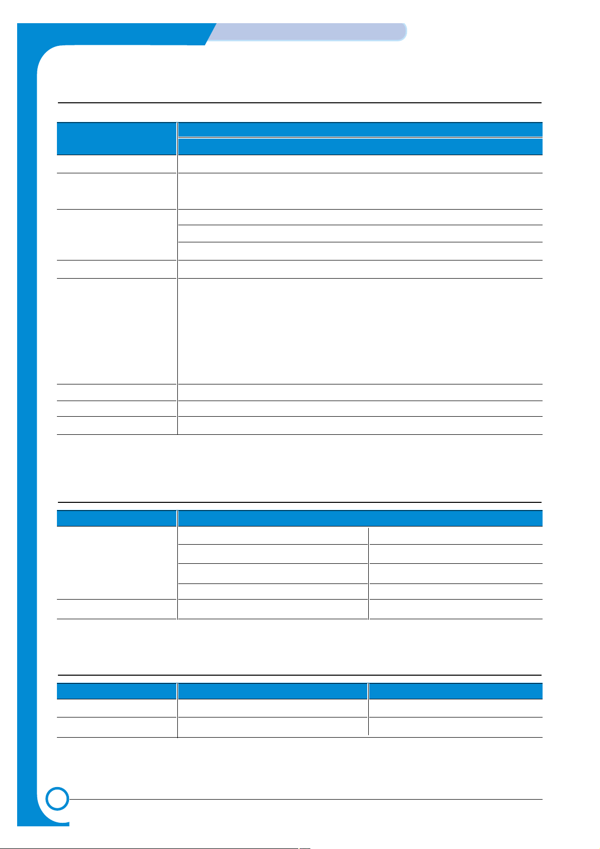
4.1.1 Front View
Output Support
Top output tray
(Face down)
Control Panel
Power switch
Paper level indicator
Tray
Manual Feeder
Manual Feeder guide
Front Cover

4-2
SUMMARY OF PRODUCT
Samsung Electronics
Service Manual
4.1.2 Rear View
Rear output tray
(Face up)
Power receptacle
Parallel port
USB port
4.1.3 Inside View
Toner cartridge
Front Cover
LED Description
4-3
Samsung Electronics
SUMMARY OF PRODUCT
Service Manual
4.1.3 Control Panel
1) On Line/Error and Toner Save LEDs
If the On Line/Error lights green, the printer is ready to print.
If the On Line/Error lights red, the printer is experiencing an error, such as jammed paper,
the open cover or the empty toner cartridge. If you press the Cancel button while the printer
is receiving data, the On Line/Error LED blinks red to cancel printing.
In Manual Feed mode, if there is no paper in the Manual Feeder, the On Line/Error LED
blinks red. Load paper into the Manual Feeder and the LED stops blinking.
If the printer is receiving data, the On Line/Error LED slowly blinks green.
If the printer is printing the received data, the On Line/Error LED blinks green fast.
If you press the Cancel button in Ready mode, this LED is on and the Toner Save mode is
enabled.
If you press this button once again, this LED is off and the Toner Save mode is disabled.
If the On Line/Error and Toner Save LEDs blink, your system has some problems. To solve
the problem.

4-4
SUMMARY OF PRODUCT
Samsung Electronics
Service Manual
2) Cancel button
Printing demo page In Ready mode, press and hold this button for about 2 seconds until
all LEDs blink slowly, and release.
Printing configuration sheet In Ready mode, press and hold this button for about 6 seconds until
all LEDs blink fast, and release.
Manual feeding Press this button each time you load a sheet of paper in the manual
feeder, when you select Manual Feed for Source from your software
application.
Cleaning inside printer In Ready mode, press and hold this button for about 10 seconds
until all LEDs turn on, and release. After cleaning the printer, one
cleaning sheet prints.
Canceling print job Press this button during printing. The On Line/Error LED blinks while
the print job is cleared from both the printer and the computer, and
then return to Ready mode. This may take some time depending on
the size of the print job.
In Manual Feed mode, you can’t cancel the print job by pressing this
button.
Toner Save mode on/off In Ready mode, press this button to turn the Toner Save mode on or
off.

4-5
Samsung Electronics
SUMMARY OF PRODUCT
Service Manual
4.2 System Layout
PTL
P
I
C
K
/
R
PR
CR
DR
SR
TR FR
OPC
L S U
Fuser
Toner Cartridge
1
1
2
2
3
6
3
4
Cassette
Manual Feeder
Transfer Roller
PTL(Per-Tramsfer-Lamp)
5
7
6
7
5
Fuser
LSU(Laser Scan Unit)
Toner Cartridge
4
MP Sensor

4-6
SUMMARY OF PRODUCT
Samsung Electronics
Service Manual
4.2.1 Feeding Part
There are the universal cassette, which loads papers, and the manual feeder, which supplies paper one by
one. The cassette has the function pad which separates paper one by one, and it has the sensor function
to check the existence of the loading paper.
- Feeding Method: Universal Cassette Type
- Feeding Standard: Center Loading
- Feeding Capacity: Cassette-250 sheets (75g/m©˜, 20lb paper standard)
Manual 1 sheet (Paper, OHP, Envelop, etc.)
- Paper detecting sensor: Photo sensor
- Paper size sensor: None
4.2.2 Transfer Ass’y
It is consisted of the PTL (pre-transfer lamp) and the Transfer Roller. The PTL sends a light to the OPC
drum, makes the current on the drum surface to low, and improves the transfer efficiency.
The transfer roller delivers the toner of the OPC drum to the paper.
- The life span: Print over 60,000 sheets (in 15~30°C)
4.2.3 Driver Ass’y
It is a power delivery unit by gearing. By driving the motor, it supplies the power to the feeding unit, the
fusing unit, and the distributing unit.
4.2.4 Fixing Part(Fuser)
- The fuser is consisted of the Heat Lamp, Heat Roller, Pressure Roller, Thermistor, and Thermostat. It
adheres the toner to the paper with a pressure and a heat to complete the printing job.
- There are two methods, the existing method which use the Heat Lamp and the Q-PID which is developed
by Samsung.
110V : Heat Lamp type Fuser
220V : Heat Lamp type or Q-PID type Fuser
4.2.4.1 Temperature-Intercepting Device (Thermostat)
The thermostat is the temperature-intercepting device, which cuts off the power for preventing an overheating or a fire when the heat lamp or the heat coil of the heat roller is overheated.
4.2.4.2 Temperature Detecting Sensor (Thermistor)
The Thermistor detects the surface temperature of the heat roller, and it maintains the regular temperature
of the heat roller by responding to the information of the temperature.
4.2.4.3 Heat Roller
The heat roller transfers the temperature from the heat lamp or heat coil to the surface to heat the paper
which passes the surface. The melted toner cannot stain the heat roller coated with Teflon.
The heating elements are heat lamp and heat coil. For this product, Q-PID method with the heat coil is
applied.
4.2.4.4 Pressure roller
The pressure roller mounted right under the heat roller is made of the silicon resin, and the surface of the
roller is coated with Teflon to fuse the toner on the paper when paper passes between the heat roller and
the pressure roller.

4-7
Samsung Electronics
SUMMARY OF PRODUCT
Service Manual
4.2.4.5 Safety Relevant Facts
• Protecting device when overheating
- 1st protecting device: H/W cuts off when detecting an overheating
- 2nd protecting device: S/W cuts off when detecting an overheating
- 3rd protecting device: Thermostat cuts off the power
• Safety device
- The power of the fuser is cut off when the front cover is open.
- The overheating safety device for customer
- Maintains the surface temperature of the Fuser Cover under 80°C and attach the caution label
inside of the rear cover where customer can find easily.
4.2.5 LSU (Laser Scanner Unit)
The LSU unit is controlled by the video controller. It scans the video data received from video controller with
laser beam by using the rotation principal of the polygon mirror to create the latent image on the OPC drum.
It is the core part of LBP.
The OPC drum rotates as the same speed as the paper feeding speed. It creates the /HS YNC signal and
sends it to the engine when the laser bean of the LSU reaches the end of the polygon mirror, and the engine
detects the /HS YNC signal to arrange the vertical line of the image on the paper. After detecting the /HS
YNC signal, the image data is sent to the LSU to arrange the its left margin on the paper.
The one side of the polygon mirror is one line for scanning.

4-8
SUMMARY OF PRODUCT
Samsung Electronics
Service Manual
4.2.6 Toner Cartridge
By using the electronic photo process, it creates a visual image. In the toner cartridge, the OPC unit and
the developer unit are in a body. The OPC unit has OPC drum and charging roller, and the developer unit
has toner, toner cartridge, supply roller, developing roller, and blade (Doctor blade)
- Developing Method: Non magnetic 1 element contacting method
- Toner: Non magnetic 1 element shatter type toner
- The life span of toner: 3,000 sheets (IDC Pattern/A4 standard)
- Toner remaining amount detecting sensor: None
- OPC Cleaning: Collect the toner by using electric static + FILM OPC
- Management of disusable toner: Collect the toner by using electric static (Clenerless Type- No
disusable toner)
- OPC Drum protecting Shutter: None
- Classifying device for toner cartridge: ID is classified by interruption of the frame channel.
4-9
Samsung Electronics
SUMMARY OF PRODUCT
Service Manual
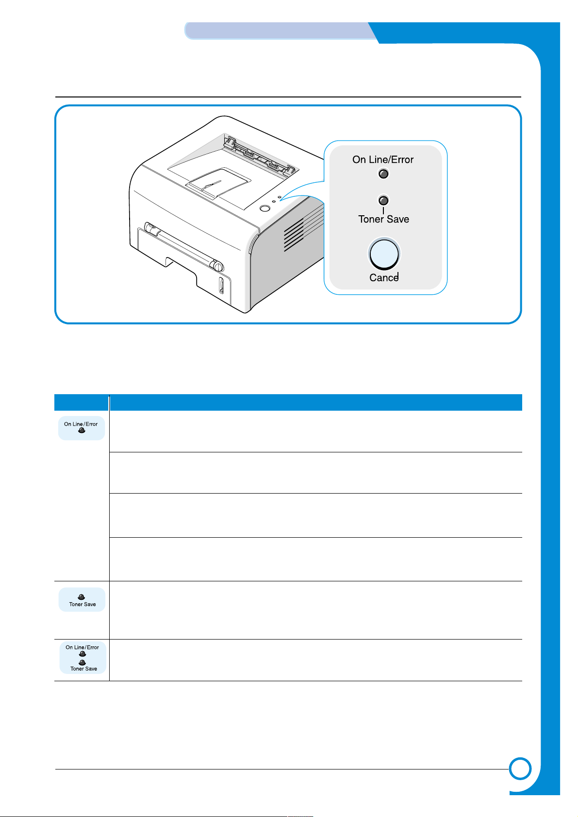
4.3 Main PBA(SPL Model)
The Engine Board and the Controller Board are in one united board, and it is consisted of CPU part and
print part in functional aspect. The CPU is functioned as the bus control, I/O handling, drivers, and PC interface. The main board sends the Current Image dlml Video data to the LSU and manages the conduct of
Electrophotography for printing. It is consisted of the circuits of the motor (paper feed, pass)
driving, clutch driving, pre-transfer lamp driving, current driving, and fan driving.
The signals from the paper feed jam sensor and paper empty sensor are directly inputted to the main
board.
ASIC
SDRAM
FLASH
MEMORY
MOTOR DRIVER IC
BUFFER
VIDEO CLK
14.7456MHz
USB CONN COMP ARATOR IC
MAIN CLK
10MHz
CLOCK
GENERA TOR IC
P ARELLEL
CONN
U32
U13 CN7CN8
U24
CN3
CN10
CN6
CN9
OSCI
U27
U16
U26
CN5
OSC2
CN2(DCU PORT) U25U20 U31

4-10
SUMMARY OF PRODUCT
Samsung Electronics
Service Manual
4.3.1 ASIC (Jupiter )
The Jupiter (16Bit RISC Processor), which is the executive controller to operate the printer function, is in
use, and the each operation block is driven by system program of the flash memory. The whole system is
controlled by driving operation block.
•Main function block
• Completely Integrated System for Embedded Applications,
• 16 Bit Risc Architecture, Efficient and Powerful ARM7TDMI CPU
• LSU Interface Module for Interfacing PVC or HPVC with LSU
• 2 Channel General Purpose DMA Controller for High Speed I/O
• Dual Memory Bus Architecture
• Operating frequency : 80MHz
• Operating power : 3.3V
• Power on reset time : under 6.6ms
4.3.2 Flash Memory
It stores the system program and downloads the system program through the PC interface.
• Capacity : 0.5M Byte
• Access Time : 70 nsec
4.3.3 SDRAM
It is used as a swath buffer, system working memory area, etc. while printing.
• Capacity :
•
Access Time : 60 nsec
4.3.4 Sensor input circuit
1) Paper Empty Sensing
The Paper empty sensor (Photo Interrupter) on the engine board informs the state of paper to CPU whether
it is empty or not with operation of the actuator.
When cassette is empty, it detects the fact by reading the D0 Bit of CPU, and then informs the fact by
selecting the second LED(yellow) among the panel LEDs.
2) MP Sensing
By operation of Actuator on the frame, the MP Sensor (Photo Interrupter) on the engine board informs the
state of paper to CPU whether it is empty or not. It reads the D0 Bit of CPU for recognizing paper in MP,
and paper is fed from MP if there is.
ML-1740
8 M byte

4-11
Samsung Electronics
SUMMARY OF PRODUCT
Service Manual
3) Paper Feeding, Toner Cartridge Sensing
When paper passes the actuator (feed sensor part), it detects the signal of Photo interrupter, informs the
paper feeding state to CPU, and then sprays the image data after certain time.
If it doesn't detect the feed sensor within 1 sec. after paper is fed, paper Jam0 is occurred (Red and Yellow
will be turned on among the OP panel LEDs), and the fact whether the developer is inserted or not is detected with the same principle. After the developer is mounted, the actuator is operated. The signal from the photo
interrupter is detected when it is passing the actuator of the sensor part. That is the developer ID sensing.
4) Paper Exit Sensing
It detects paper state whether paper gets out from the set with operation of exit sensor on the engine board
and actuator on the frame. Paper detects the on/off time of exit sensor , and the normal operation or jam information is informed to the CPU.
The paper JAM2 is informed. (Red, Yellow LED will be turned on among the OP panel LEDs)
5) Cover Open Sensing
The Cover open sensor is located on the front cover. After the front cover is opened, +24V (DC fan, solenoid,
main motor, polygon motor part of LSU, HVPS), which is supplied to the each unit, is cut off.
The cover-open sensing is operated by the D0 bit of CPU, and the developer ID sensing is operated.
In this case, the red LED among OP panel LEDs will be ON for informing the facts to user.
6) DC FAN / SOLENOID Driving
It is driven by transistor and controlled by D6 bit of CPU.
When it is high, the fan is driving by turning on the TR, and it is off when the sleep mode is selected.
There are two solenoids, and they are driven by paper pick-up and MP signal. Its driving time is 300ms. The
diode protects the driving TR from the noise pulse, which is flown when the solenoid is de-energizing.
7) Motor Driving
The motor driving circuit is formed when the Driver IC is selected in the first place. The A3977 (Motor driver
IC) is used in this case. But, the resistance Rs value of sensing and the voltage value of the V reference can
be changed by motor driving voltage value.

4-12
SUMMARY OF PRODUCT
Samsung Electronics
Service Manual
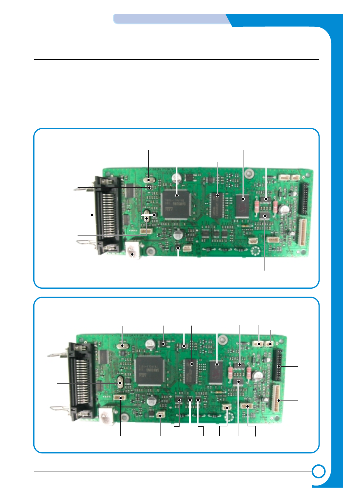
4.4 SMPS & HVPS
The SMPS supplies the DC power to the system.
It takes 110V/220V and outputs the +3.3V, +5V and +24V to supply the power to the main board and ADF
board.
The HVPS part creates the high voltage of THV/MHV/Supply/Dev and supplies it to the developer part for
making the best condition to display the image. The HVPS part takes the 24V and outputs the high voltage
for THV/MHV/BIAS, and the outputted high voltage is supplied to the toner, OPC cartridge, and transfer
roller.
MAIN PBA CON.
CN3
(FAN CON.)
CN1
(H/L CON.)
F101
250V L2A
EXIT SENSOR
CN4
(PANEL CON.)
MHV
OPC
DEV
SUPPLY
THV
COVER OPEN SWITCH
MANUAL SENSOR
FEED SENSOR
PAPER-EMPTY SENSOR
F1
110V : 125V/8A
220V : 250V T 5A H
F2
110V : 125V/3A
220V : 250V 2A H

4-13
Samsung Electronics
SUMMARY OF PRODUCT
Service Manual
4.4.1 HVPS(High Voltage Power Supply)
1) Transfer High Voltage (THV+)
- Function: It is a voltage to transfer a toner developed on OPC drum to a paper.
- Output voltage: Maximum +5.0KV ±5% (Duty changeable, unload)
- 1.0KV ±15%(When cleaning, 200MOhm)
- Error: If THV (+) doesn't output, a ghost status (same character is printed after one cycle (76mm)
of OPC) with a low density occurs due to a toner on OPC drum cannot normally transfer to a
paper.
2) Charge Voltage (MHV)
- Function: It is a voltage to charge entire surface of OPC with -900V ~ -1000V.
- Output voltage: -1.3KV ~ 1.8KV DC ±50V
- Error: If MHV doesn't output, a black paper is printed out because toner on developing roller
moves to OPC drum due to the surface of OPC is not charged.
3)Cleaning Voltage (THV-)
- Function: It removes a dirty on a surface by sending a minus toner in a transfer roller to an OPC
drum to recover toners.
- Output Voltage: There is no feedback control, so change range of output is big up to load.
- Error: Toner contamination occurs at a backside of a printed-paper.
4) Developing Voltage (DEV)
- Function: It is a voltage to develop a toner with using a difference of electronic potential on an
exposed part by LSU (Laser Scanning Unit).
* Generally, the electronic potential of exposed OPC is -180V and exposed developer is -350V
when printing, so toner with minus (-) is developed on an exposed part.
- Output voltage: -200V ~ 600V DC ±20V
- Error: 1. If DEV is GND, a density is going significantly down.
2. If DEV is floating due to instable contacting point of terminal, and etc., a density is significantly going up.
5) Supply Voltage(SUP)
- Function: It is a voltage to supply toner to a developing roller.
- Output voltage: : -400V ~ 800V DC °æ 50V(Use ZENER, DEV gear)
- Error: 1. If SUP is GND, a density is dramatically going down.
2. If SUP is floating due to instable contacting point of terminal, and etc., a density is significantly going down as much as it cannot be recognized with eyes.
 Loading...