

Samsung ML1650 Series
SERVICE
LASER PRINTER
ML-1650Series
ML-1650 / ML-1651N
Manual
LASER PRINTER CONTENTS
1. Precautions
2. Specifications
3. Disassembly and Reassembly
4. Troubleshooting
5. Exploded Views and Parts List
6. Block Diagram
7. Connection Diagram

© Samsung Electronics Co.,Ltd. September 2001
Printed in Korea.
VERSION NO. : 2.00 CODE : JC-0055A
This service manual is also provided on the web,
the ITSELF system f Samsung Electronics Co., Ltd.
“http://itself.sec.samsung.co.kr”

This manual is stated and
provided for service description.
All rights reserved. Any parts of the
information in this manual are prohibited
from free duplication, use or translation
without prior written approval except in
cases allowed by the Copyright Act.
Specifications are subject to change without
prior notice.
Copyright (c) 2001. 6.
Samsung Electronics Digital Printing CS Group
Read each caution carefully:
1. Do not use this printer near water or when exposed to
inclement weather.
2. Do not place this printer on an unstable cart, stand or
table; the product may fall, causing serious damage
to the product.
3. Slots and openings in the cabinet are provided for
ventilation. To ensure reliable operation and to protect
the printer from ever heating, do not block or cover
any of these openings. Do not place the printer in an
enclosure unless the enclosure provides adequate
ventilation.
4. Never push objects of any kind into the printer through
the cabinet ventilation slots as they may touch dangerous high voltage points, create short circuits,
cause a fire, or produce an electrical shock. Never
spill liquid of any kind on the printer.
5. Do not place the printer in a location where someone
may trip on the cords.
6. Select a work surface that is large enough to hold the
printer.
7. Position the printer within six feet of the computer and
within five feet of an electrical outlet.
8. Operate this printer using the power source (110V,
220V, etc) indicated on the marking label. If you are
not sure of the type of power source available, consult
your dealer or local power company.
9. If you need to use an extension power cord with this
printer, make sure that it uses a three-wire grounded
cord and that the total ampere ratings for all of the
products using the extension do not exceed the
extension cord ampere rating. Also, make sure that
the total of all products plugged into the wall outlet
does not exceed 15 amperes.
10. Do not allow anything to rest on the power cord or
data communications cable.
11. Unplug this printer from the wall outlet before clean-
ing. Do not use liquid cleaners or aerosol sprays. Use
a damp cloth for cleaning.
12. Do not touch the surface of the photo-sensitive drum
as marks or scratches may impair print quality.
13. Do not expose the drum unit to direct light for pro-
longed periods.
14. Use only standard papers, OHP films, and approved
envelopes. Feed OHP films though the manual feed
slot only . See specifications for approved papers and
envelopes.
15. Other than replacing consumables such as paper
and toner, refer all questions to qualified service personnel.
Precautions
1-1
Samsung Electronics
1. Precautions
1-1 Safety Precautions
Please read the following carefully to prevent any accidents and not to damage the unit during service.
Especially mind the safety on the part with
this mark.
You must use regular parts described in specifications for the parts inflammable and where the
current can be flown. Otherwise any hazard
such as an electric shock or a fire could occur.
LASER STATEMENT (LASERTURVALLISUUS)
WARNING : NEVER OPERATE AND SERVICE THE PRINTER
WITH THE PROTECTIVE COVER REMOVED
FROM LASER/SCANNER ASSEMBLY. THE
REFLECTIVE BEAM, ALTHOUGH INVISIBLE, CAN
DAMAGE YOUR EYES.
Class 1 laser product
Luokan 1 laserlaite
Klass 1 laser apparat
Allonpituus 770-795nm
Teho 0.3mW±0.03mW
CAUTION
VORSICHT
ATTENTION
ATTENZIONE
PRECAUCION
CAUTION : Avoid exposure to invisible laser radiation when the
development unit is not installed.
INVISIBLE LASER RADIATION WHEN
THIS COVER OPEN. DO NOT OPEN
THIS COVER.
UNSICHTBARE LASERSTRAHLUNG,
WENN ABDECKUNG GEOFFNET.
NIGHT DEM STRAHLAUSSETZEN.
REYONNEMENT LASER INVISIBLE EN CAS
D’OUVERTURE. EXPOSITION DANGERUSE AU
FAISCEAU.
RADIAZIONE LASER INVISIBLE IN CASO DI
APERTURA. EVITARE L’ESPOSIZONE LAFASCIO.
REDIACION LASER INVISIBLE CUANDO SE
ABRE. EVITAR EXPONERSE AL RAYO.

Precautions
1-2
Samsung Electronics
1-2 Precautions on Disassembly and Reassembly
Very careful precautions should be taken when replacing
parts. Before replacing, please check cables because
you cannot put the cables that you removed for replacing
parts into the proper place if you would not make sure of
where they were connected and in which condition.
Please do the following before disassembling for a repair
or replacement of parts.
1. Pull out paper cassette, printer cartridge installed.
Especially careful not to be scratched by the surface of
developer or not to expose them to light.
2. Turn the power switch off.
3. Take out the power plug, printer cable from the printer.
4. Use only the same type of part as original when replacing parts.
5. Do not force to open or fasten plastic material compo-
nents.
6. Be careful that small parts such as screws should not
get in the printer.
7. When disassembling, assembling, also observe small
components are located in place.
8. If you uncover and turn the machine over to replace
some parts, toner or paper particles may contaminate
the LSU window. Protect the LSU window with clean
paper.
Releasing Plastic Latches
Many of parts are held in
place with plastic latches.
The latches break easily :
release them carefully.
To remove such parts,
press the hook end of the
latch away from the part to
which it is latched.
Precautions
1-3
Samsung Electronics
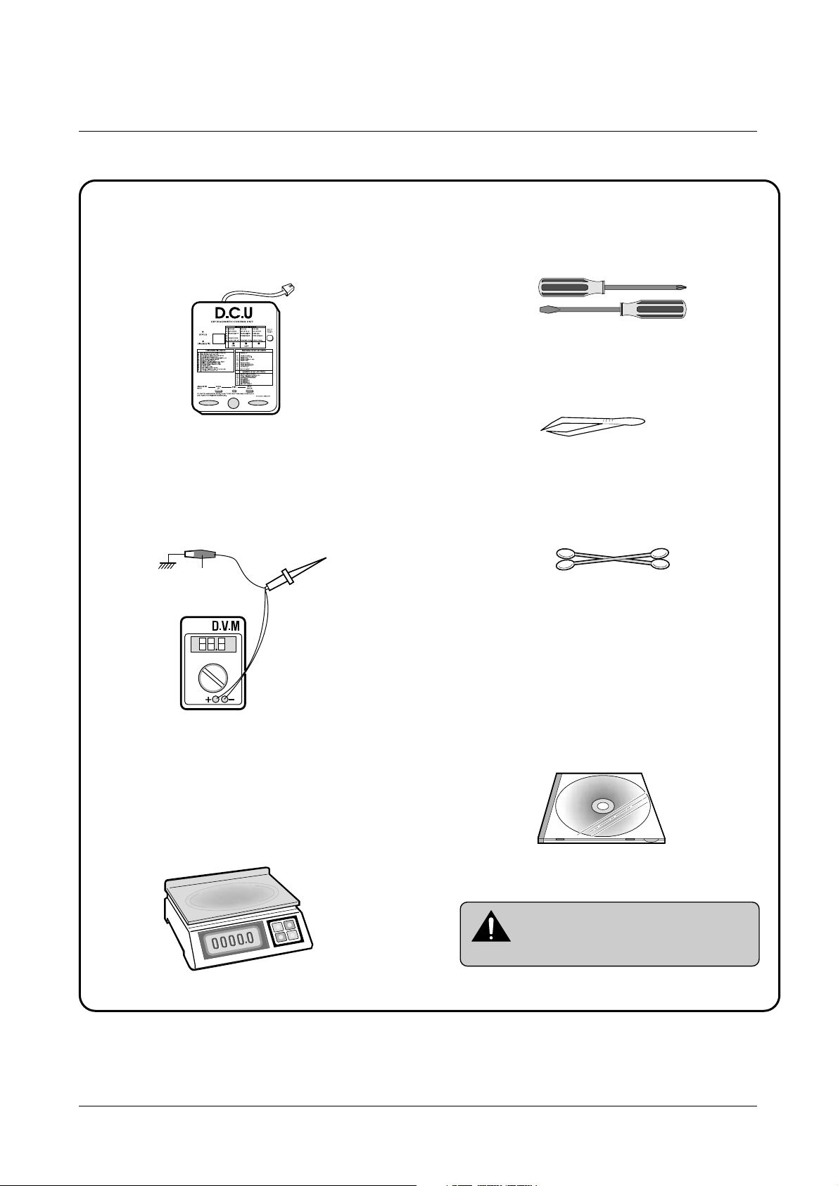
1-3 Tools for Troubleshooting
The following tools are recommended for safe and smooth troubleshooting described in this service manual.
DCU(Diagnostic Control Unit)
Standard: Test equipment to diagnose the Laser
printer supplied by Samsung Electronics.
DVM(Digital Volt Meter)
Standard: Indicates more than 3 digits.
Electronic Scale
Standard: Equipment to check the weight of consumables(toner cartridge) supplied by Samsung
Electronics. (The gram unit can be measured.)
Driver
Standard: "-" type, "+" type (M3 long, M3 short,
M2 long, M2 short).
Pinset
Standard: For general home use, small type.
Cotton Swab
Standard: For general home use, for medical ser-
vice.
Cleaning Equipments a IPA(Isopropyl
Alcohol)dry cloth or a soft stuff neutral
detergent.
Software(Driver) installation CD ROM
Mind your hands not to be touched when
you disassemble and reassemble PBAASS'Y ,
such as the main board, SMPS, HVPS.
Note
Ground
1
2
3
4
5
6
7
8
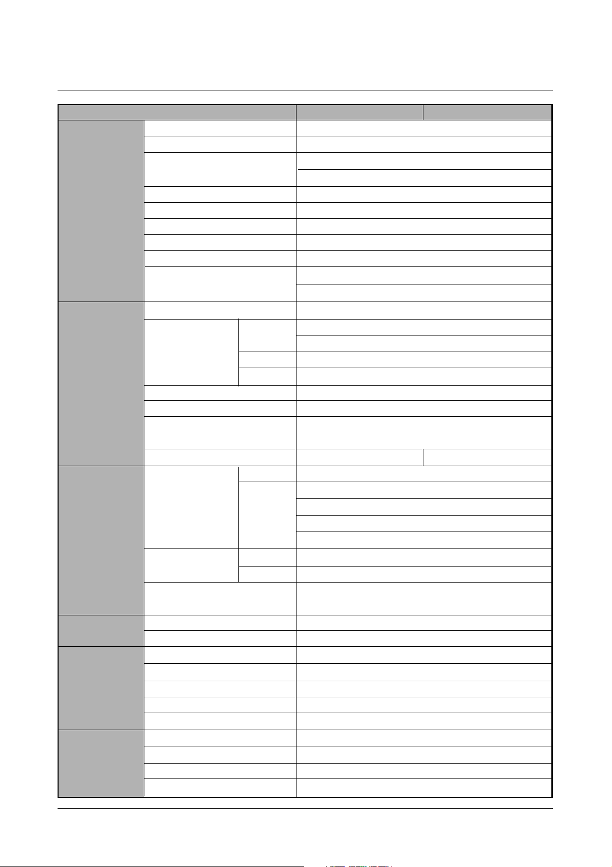
17 PPM(Letter) , 16PPM(A4)
1200 * 1200
Tray 1 : Less than 14 seconds
Tray 2 : Less than 17 seconds
Less than 40 seconds
Print : 300 W, Sleep mode : Less than 20 W
361 x 409 x 294.5 mm
12.4 Kg/27.3lb (SET)
Stand by : Less than 35 dB, Operating : Less than 49dB
AC 100~127V , 50 Hz
AC 220~240V , 60 Hz
Power PC (166 MHz)
Standard : 16Mbyte
Option DIMM Module ; 16, 32,64,128M byte
4 Mbyte (16M bit x 2 : Program) Flash Memory
512 bytes
PCL6, PS 3(Option)
IEEE1284, USB, Network
Windows 95/98/2000/Me/NT,
Linux(Radhat 6.0 ↑), iMac(Mac OS 8.0 ↑)
Option Default
550 sheets (75g/m2)
100 sheets (75g/m2)
20 sheets (OHP)
10 sheets (Letter, card)
25 sheets (Label)
250 sheets
100 sheets
A4, Letter. Legal, Executive, B5, A5, Folio, 7 3/4(Monarch),
#10, DL, C5, C6, B5
Single Cartridge
8,000 sheets (Set : 4,000 sheets)
8,000 sheets (Set : 4,000 sheets)
60,000 sheets
60,000 sheets
125,000 sheets
40,000 sheets
3Key, 4LEDs
No
YES
YES(Button)
Specifications
2-1
Samsung Electronics
2. Specifications
Speed
Resolution
First Print Time
Warm-Up T ime
Power Consump.
Dimension(W * D * H)
Weight
Acoustic Noice
Power Rating
Processor
Memory
Emulation
Interface
OS Support
N/W
Input
Output
Media Type
Type
Life
Cartridge
Pick up Roller
Feed Roller
Transfer Roller
Fuser
Key & LED
LCD
Toner Save
Reprint
RAM
ROM
EEPROM
Cassette
MP Tray
Face down
Face up
Engine
Controller
Paper
T oner
User interface
ML-1650 ML-1651N
Specifications
2-2
Samsung Electronics
10 ~32˚c (50˚F ~ 90˚F)
20 ~ 80 % RH
-200 ~40˚c (4˚F ~ 104˚F)
10 ~90 % RH
Windows 95/98 and Windows NT (3.51, 4.x )
Netware (3.x, 4.x), NDS and Bindery Mode /RPRINT,
PSERVER Mode
UNIX and Apple Talk
TCP/IP : Windows 95/98, Windows NT, UNIX
IPX/SPX : Windows 95/98, Novell Netware
DLC/LLC : Windows 95/98, Windows NT
Ethertalk : Apple Talk
SNMP : for Network Printer Administration
Ethernet 10/100 BaseTX (Auto Negotiation)
Samsung’s Admin. Software Utility (SyncThru)
SNMP and MIB-II Support,
GUI based utility for Windows Systems and Test based
utility for UNIX Systems
HTTP server for web browser based network management (can manage NPC and printer options on Web
Browser)
Operation Environment
Storage Environment
Network Operating Systems
Network Protocols Supported
Network Card Interface
Network Management S/W
Temperature
Humidity
Temperature
Humidity
Environment
Network
ML-1650 ML-1651N

Disassembly and Reassembly
3-1
Samsung Electronics
When you disassemble and reassemble components, you must use extreme caution. The close proximity of
cables to moving parts makes proper routing a must. If components are removed, any cables disturbed by
the procedure must be restored as close as possible to their original positions. Before removing any
component from the machine, note the cable routing that will be affected.
Whenever servicing the machine, you must perform as follows:
1. Remove the paper cassette(s), and the print cartridge. Do not expose the cartridge to direct room light or
sun light, and be careful not to scratch the drum surface.
2. Turn the power switch off.
3. Unplug all the cables from the printer.
4. Replace with only an authorized component.
5. Do not force to open or fasten a plastic material component.
6. Be careful no obstacles are included when you reassemble components.
7. When you reassemble components, be careful small size components are located in place.
8. If you turn the machine over to replace some parts, toner or paper particles may contaminate the LSU
window. Protect the LSU window with clean paper.
Releasing Plastic Latches
Many of the parts are held in place with plastic latches.
The latches break easily; release them carefully.
To remove such parts, press the hook end of the latch away from
the part to which it is latched.
3-1 General Precautions on Disassembly
3. Disassembly and Reassembly
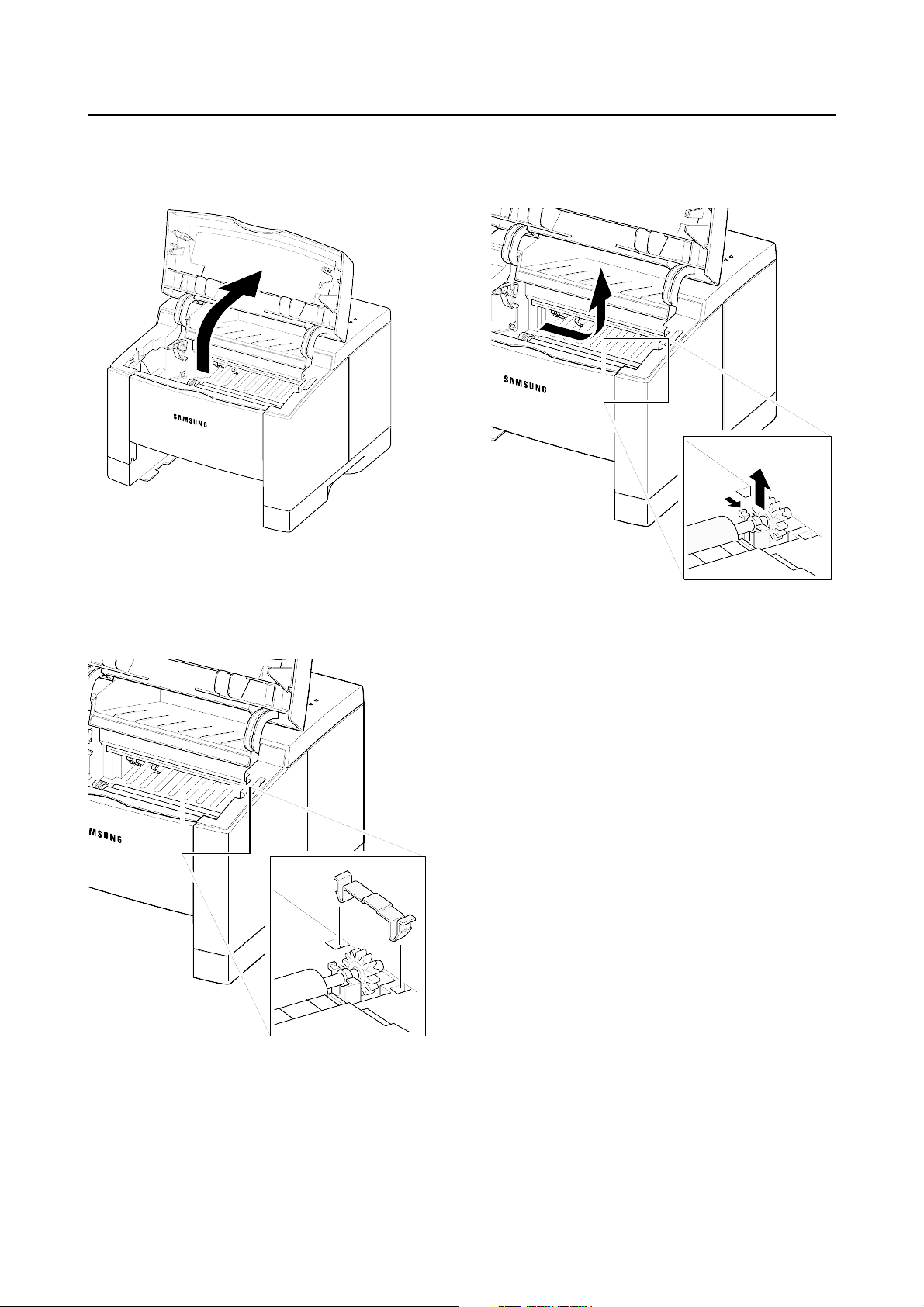
1. Open the printer cover.
2. Remove the cap.
3. Hold the cap at the both end of the roller, then
remove the roller.
Disassembly and Reassembly
3-2
Samsung Electronics
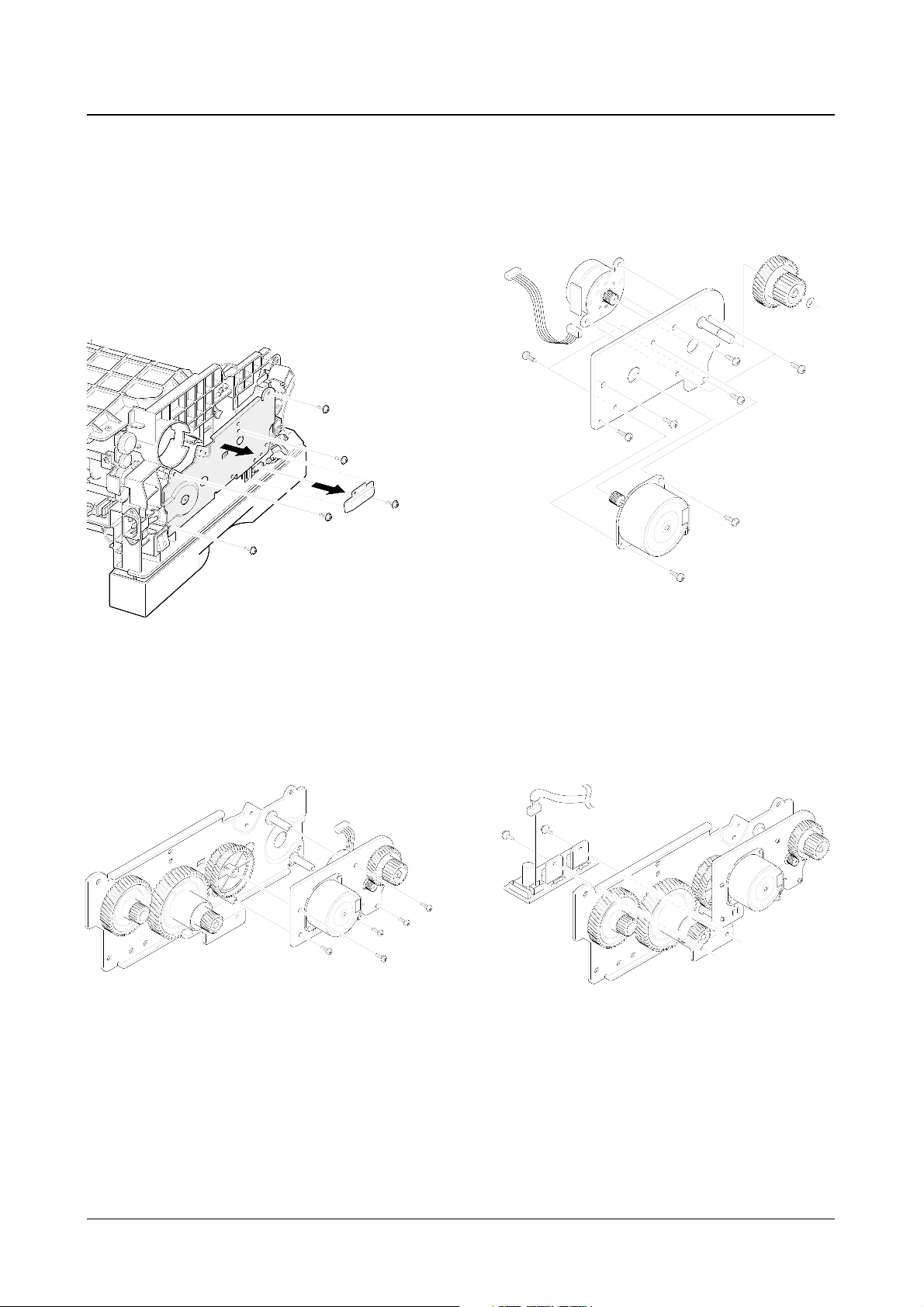
3-2 Transfer Roller
Disassembly and Reassembly
3-3
Samsung Electronics
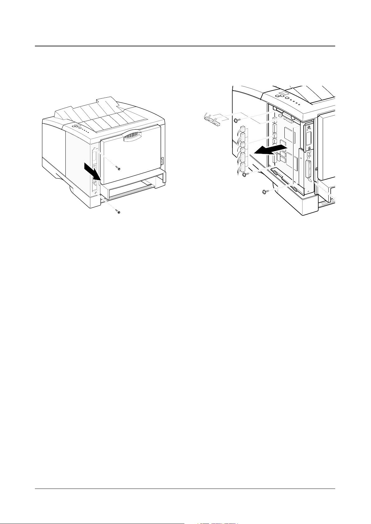
1. Remove two screws and remove the
controller cover.
2. Remove five screws securing the board and
unplug all connectors, and then take the
controller board out of the printer.
3-3 Controller Board
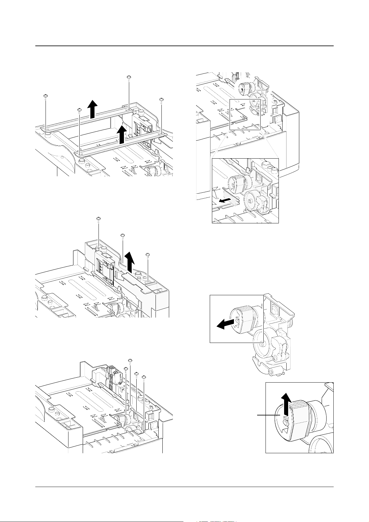
1. Turn the printer upside down. Remove four
screws, then remove the bar cross bottom.
2. Remove three screws from the left base
bracket, and take the bracket out.
3. Remove four screws securing the pickup
assembly.
4. Take the assembly out.
5. Check the pickup rubber wear. If the rubber is
heavily worn, replace it with a new one.
Disassembly and Reassembly
3-4
Samsung Electronics
Squeeze this tab to
remove the rubber.
3-4 Pickup Assembly
Push the solenoid if
you have difficulty to
remove the pickup
assembly.
Disassembly and Reassembly
3-5
Samsung Electronics
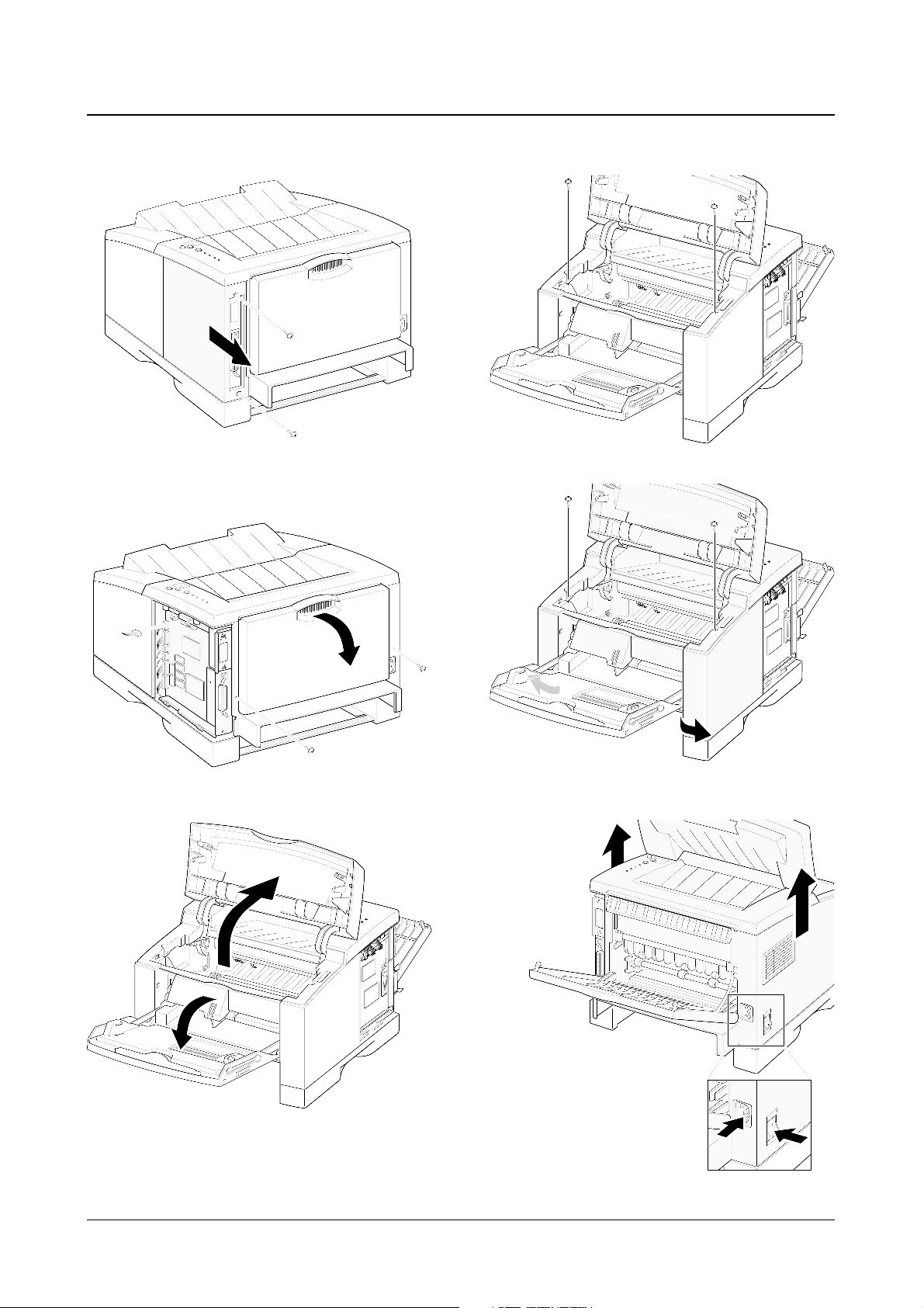
1. Remove two screws and remove the controller
cover.
2. Remove two screws at the back of the printer and
unplug one connector from the board, then open
the rear cover.
3. Open the printer cover, and open the MP tray.
4. Remove two screws securing the main cover.
5. Unlatch the front ends of the cover.
|6. Slide the main cover upward, out of the printer.
3-5 Main Cover
Note that the power
switch and the power
connecter are properly
released when you
remove the cover.
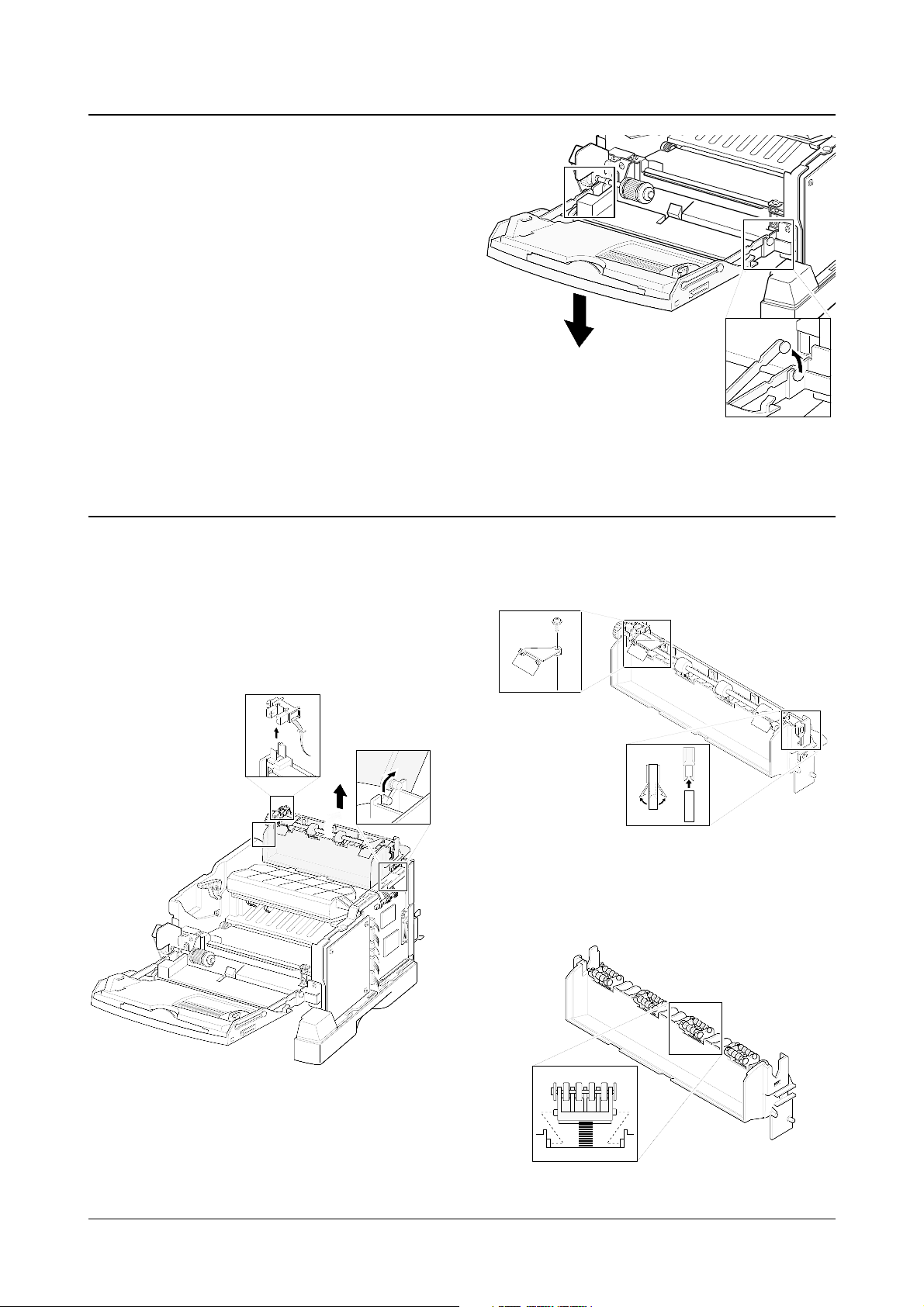
1. Before you remove the exit assembly, you
should remove:
-Main Cover (see page 3-5)
2. Remove the exit tray in the direction of arrow.
3. If you want to remove the roller shaft, unlatch
both ends of the shaft and take it out.
4. If you want to remove the exit roller, squeeze
the bottom of the roller and take it out.
Disassembly and Reassembly
3-6
Samsung Electronics
1. Before you remove the MP tray, you should
remove:
-Main Cover (see page 3-5)
2. Remove the stoppers securing the MP tray.
3-6 MP (Multi-Purpose) Tray
3-7 Exit Assembly
Disassembly and Reassembly
3-7
Samsung Electronics
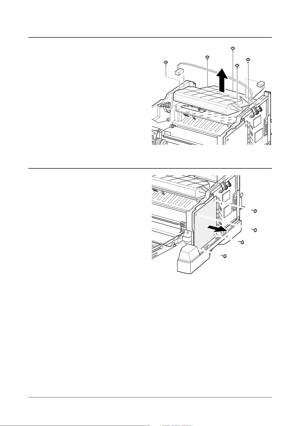
1. Before you remove the LSU, you should remove:
-Main Cover (see page 3-5)
-Exit assembly (see page 3-7)
2. Remove five screws, and remove the LSU. Then
unplug two connectors from the LSU.
3-8 LSU
1. Before you remove the HVPS board, you
should remove:
-Main Cover (see page 3-5)
2. Remove four screws and take the HVPS
board out.
3-9 HVPS board
Disassembly and Reassembly
3-8
Samsung Electronics
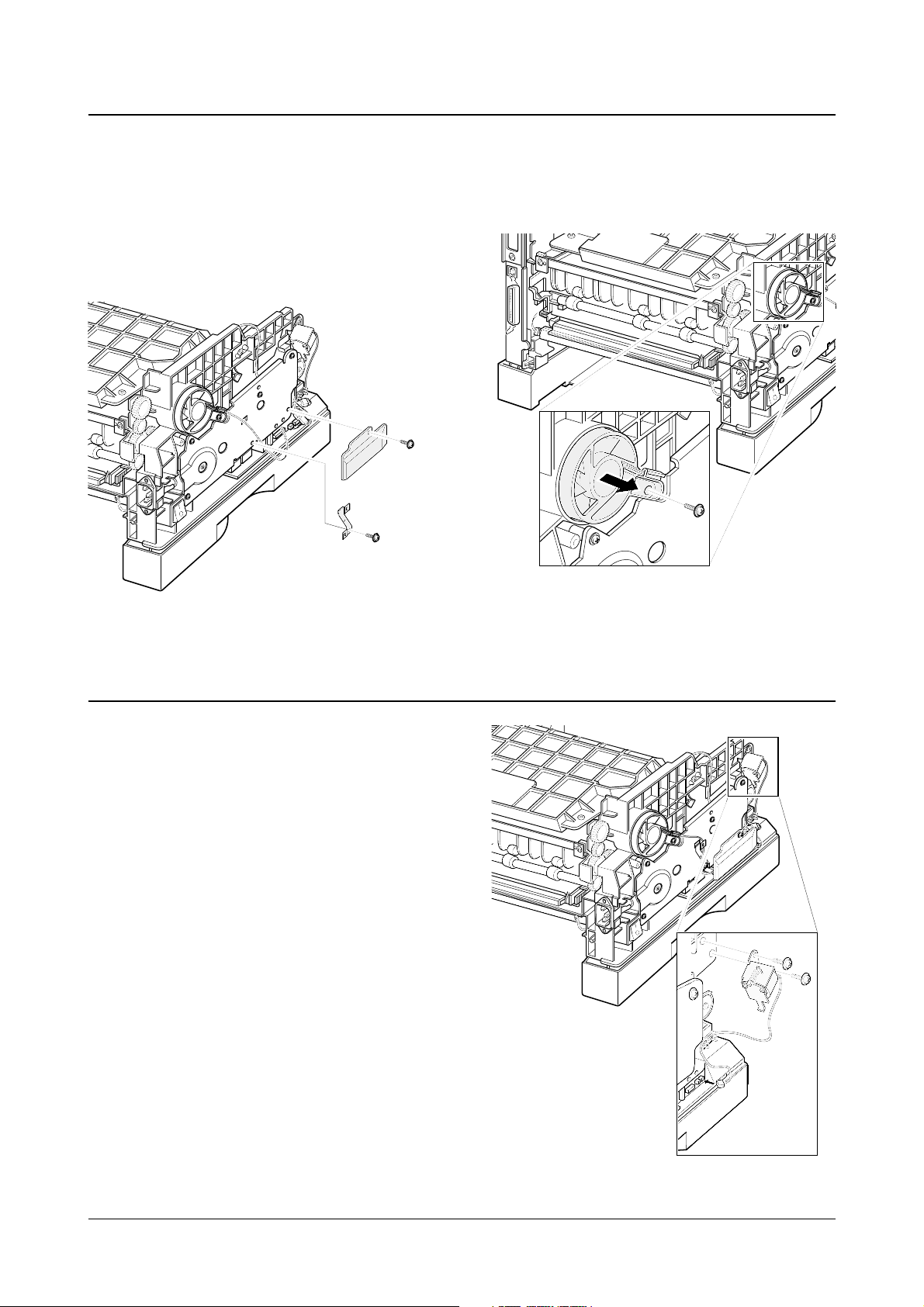
1. Before you remove the fan, you should remove:
-Main Cover (see page 3-5)
2. Remove two screws securing the connector
cover and harness bracket from the gear
bracket.
3. Remove one screw, and remove the fan.
Then unplug one connector.
3-10 Fan
1. Before you remove the solenoid, you should
remove:
-Main Cover (see page 3-5)
2. Remove two screws, and remove the
solenoid. Then unplug one connector.
3-11 Solenoid
Disassembly and Reassembly
3-9
Samsung Electronics
1. Before you remove the drive assembly, you
should remove:
-Main Cover (see page 3-5)
-Fan (see page 3-9)
2. Remove four screws securing the drive
assembly from the gear bracket and unplug
one connector from the motor, and then take
the drive assembly out.
3. If you want to remove the motor assembly from
the drive assembly, remove five screws
securing the motor assembly to the gear
bracket.
4. If you want to remove the step motor, remove
four screws securing the step motor from the
motor bracket and unplug two connector from
the motor.
5. If you want to remove the motor joint PCB,
remove two screws securing the motor joint
PCB from the gear bracket and unplug one
connector from the motor joint PCB.
3-12 Drive Assembly
Disassembly and Reassembly
3-10
Samsung Electronics
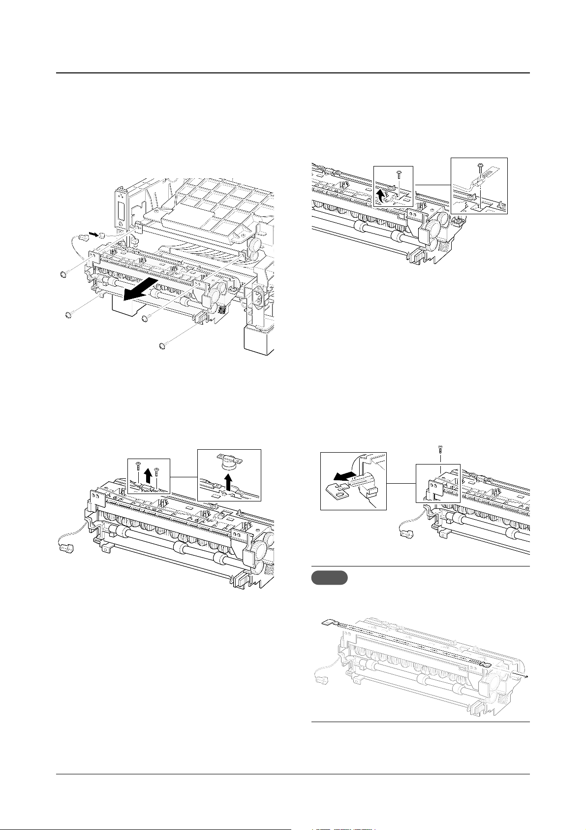
1. Before you remove the fuser, you should remov
e:
-Main Cover (see page 3-5)
2. Remove four screws and unplug one connector, and then remove the fuser assembly.
♦ To remove the thermostat from the fuser
assembly
Remove two screws and take the thermostat out.
♦ To remove the thermistor from the fuser
assembly :
Remove one screw, and release the wire from the
three holders, and then take the thermistor out.
♦ To remove the halogen lamp from the fuser
assembly :
Remove two screws and take the halogen lamp
out of the fuser assembly.
Note When you reassemble the halogen
lamp, make sure that it is inserted into
the slot properly.
3-13 Fuser Assembly
Disassembly and Reassembly
3-11
Samsung Electronics
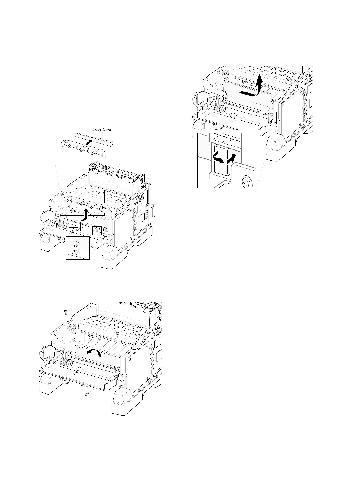
1. Before you remove the guide feed & PTL, you
should remove:
-Main Cover (see page 3-5)
2. Release the latches on the erase lamp from the MPF
ASS’Y and unplug one connector, then remove the
PTL.
3. Remove three screws and raise the guide feed in the
direction of arrow.
4. Remove the guide feed& erase PTL.
3-14 Guide Feed & Erase Lamp
Disassembly and Reassembly
3-12
Samsung Electronics
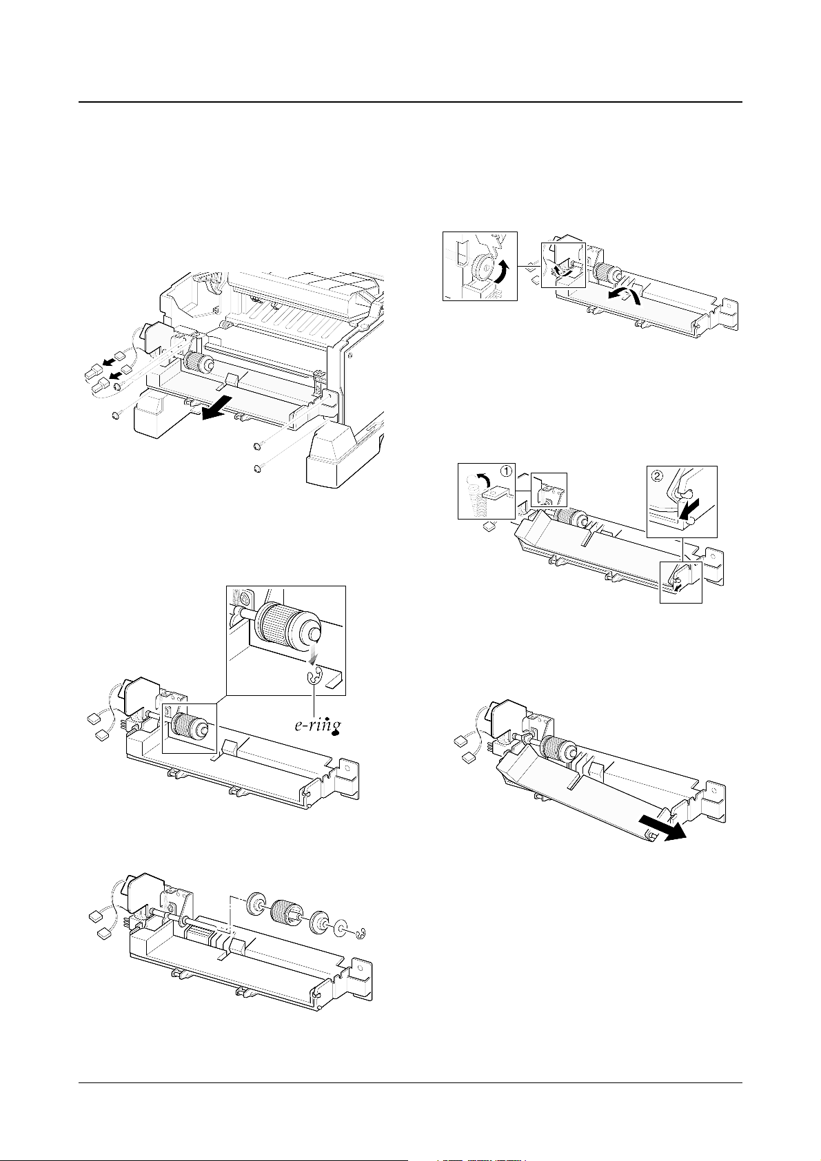
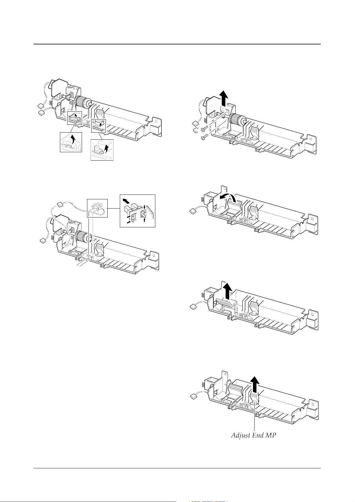
1. Before you remove the MPF assembly, you
should remove:
-Main Cover (see page 3-5)
2. Unplug two connectors and remove five
screws, and then take the MPF assembly out.
♦ To replace the pickup roller :
1. Remove the e-ring.
2. Remove the roller.
♦ To replace the nockup plate :
1. Turn the gear shown in the square in the
direction of arrow to release the nockup plate.
2. Remove the spring , then release the right end
of the plate.
3. Remove the nockup plate.
3-15 MPF Assembly and Miscellaneous on MPF Assembly
Disassembly and Reassembly
3-13
Samsung Electronics
♦ To replace the Paper Empty (PE) sensor :
1. Release the wire from the two holders.
2. Raise the pickup holder in the direction of
arrow.
♦ To replace the pickup holder and the Adjust
End MP:
1. Remove two screws and remove the MPT
bracket.
2. Unlatch the PE sensor, then take it out.
3. Remove the pickup holder.
4. Remove the Adjust End MP
Disassembly and Reassembly
3-14
Samsung Electronics
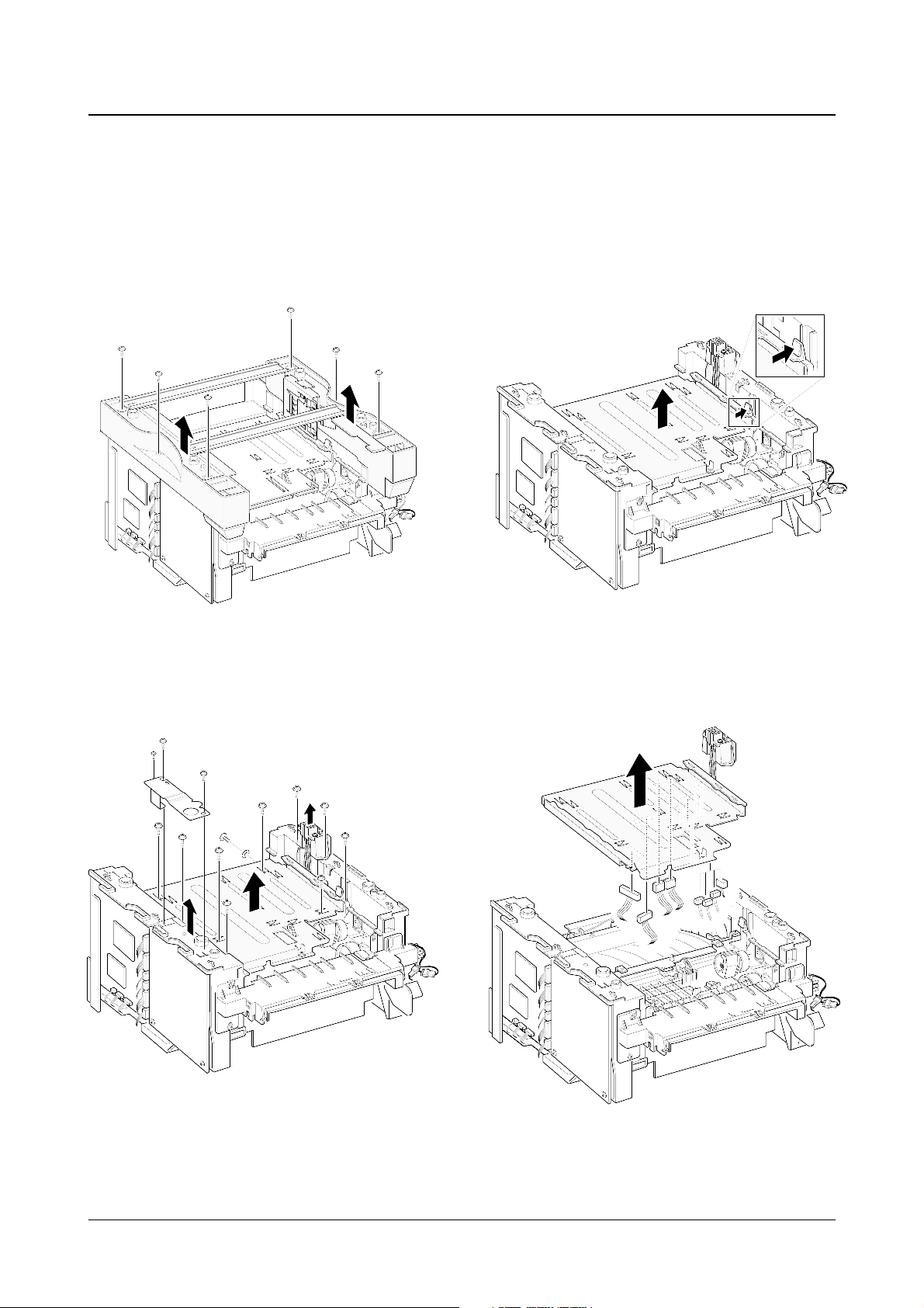
1. Before you remove the engine board, you should
remove:
-Main Cover (see page 3-5)
2. Remove six screws from the left and the right base
bracket and take them out.
3. Remove eight screws securing the PCU shield and
remove two screws securing the SCF connector , and
then take the PCU shield out of the printer.
4. While you push the latch to release the PCU shield,
take the PCU shield out of the printer.
5. Unplug all connectors from the PCU shield, and
remove the shield.
3-16 Engine Board and Miscellaneous
Disassembly and Reassembly
3-15
Samsung Electronics
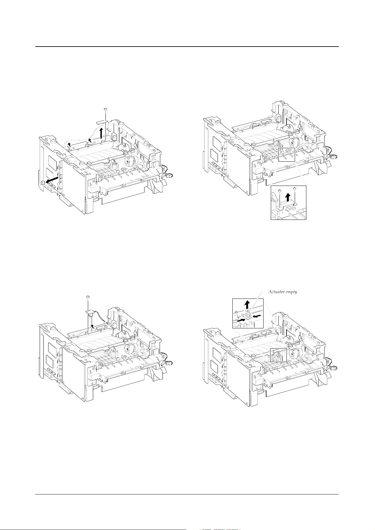
♦ To replace the exit board :
Unplug one connector from the controller board
and remove one screw securing the board.
Then release the wire from two holders and
take the board out.
♦ To replace the fuser sensor :
Remove two screws and take it out.
♦ To replace the Cap sensor :
Remove two screws and take it out.
♦ To replace the actuator empty :
Take the sensor out while you squeeze the both
ends of the sensor.
Disassembly and Reassembly
3-16
Samsung Electronics
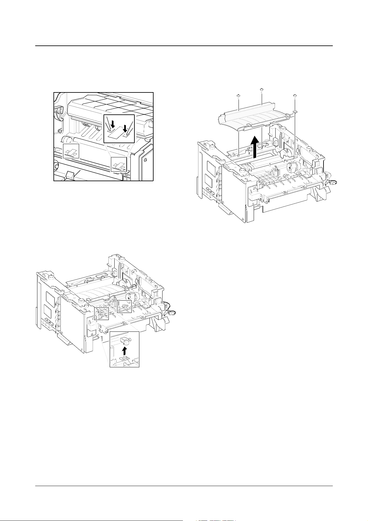
♦ To replace the actuator feed
1. Turn the mechanism back and push down the
points as shown to unlatch the actuator feed.
2. Turn the unit over again, and remove the
actuator feed.
♦ To remove the transfer guide :
Remove three screws and take the guide out.

Troubleshooting
4-1
Samsung Electronics
4. Troubleshooting
4-1 How to use DCU
4-1-1 DCU Setup......................................Page(4-2)
4-1-2 Code ................................................Page(4-2)
4-1-3 Self Diagnostic Mode......................Page(4-3)
4-1-4 Self Test Button ................................Page(4-4)
4-1-5 Paper Path Layout...........................Page(4-4)
4-1-6 DCU Panel .......................................Page(4-5)
4-2 The cause and solution of Bad image
4-2-1 Vertical Black Line and Band..........Page(4-6)
4-2-2 Vertical White Line...........................Page(4-6)
4-2-3 Horizontal Black Band .....................Page(4-7)
4-2-4 Black/White Spot..............................Page(4-7)
4-2-5 Light Image.......................................Page(4-8)
4-2-6 Dark Image or a Black.....................Page(4-8)
4-2-7 Uneven Density................................Page(4-9)
4-2-8 Background ......................................Page(4-9)
4-2-9 Ghost (1)...........................................Page(4-10)
4-2-10 Ghost (2)..........................................Page(4-10)
4-2-11 Ghost (3)..........................................Page(4-11)
4-2-12 Ghost (4) .........................................Page(4-11)
4-2-13 Satins on the Face of Page............Page(4-11)
4-2-14 Satins on Back of Page..................Page(4-12)
4-2-15 Blank Page Print out (1) .................Page(4-12)
4-2-16 Blank Page Print out (2) .................Page(4-12)
4-3 The cause and solution of the bad discharge
4-3-1 Wrong Print Position.......................Page(4-13)
4-3-2 JAM 0...............................................Page(4-13)
4-3-3 JAM 1...............................................Page(4-14)
4-3-4 JAM 2...............................................Page(4-14)
4-3-5 Multi-Feeding...................................Page(4-15)
4-3-6 Paper rolled in the fuser .................Page(4-15)
4-3-7 OPC.................................................Page(4-16)
4-4 The cause and solution of the malfunction
4-4-1 All LEDs blinking (Fuser Error)........Page(4-17)
4-4-2 All LEDs blinking (SCAN ERROR).Page(4-17)
4-4-3 Not function of the gear of the fuser due to
melting away.....................................Page(4-18)
4-4-4 Paper Empty.....................................Page(4-18)
4-4-5 Paper Empty without indication.......Page(4-18)
4-4-6 Cover Open......................................Page(4-19)
4-4-7 No lamp on when the cover is open
...........................................................Page(4-19)
4-4-8 Defective motor operation ...............Page(4-20)
4-4-9 No Power..........................................Page(4-20)
4-4-10 Vertical Line Getting Curved.........Page(4-21)
4-5 Toner Cartridge Service
4-5-1 Precautions on Safe-keeping of Toner Cartridge
..........................................................Page(4-22)
4-5-2 Service for the Life of Toner Cartridge
..........................................................Page(4-22)
4-5-3 Service for Judgement of Inferior Expendables
and the Standard of Guarantee.....Page(4-22)
4-5-4 Signs and Measures at Poor toner cartridge
..........................................................Page(4-23)
4-6 The cause and solutions of bad environment
of the software
4-6-1 The printer is not working (1)...........Page(4-26)
4-6-2 The printer is not working (2) .........Page(4-27)
4-6-3 Abnormal Printing.............................Page(4-28)
4-6-4 SPOOL Error ...................................Page(4-29)

Troubleshooting
4-2
Samsung Electronics
4-1 How to use DCU
4-1-1 DCU Setup
You can examine the malfunction of the printer. To perform DCU, open the front discharge cover and leave the connect
the harness wire(10 pin/4 pin) to the CN10(4 pin) of the Main control board.
4-1-2 Code
Connect DCU to the printer and turn the power on. It show 7 LED on the panel and each code tells the function of the
printer.
Normal Code
While printing or warming up, it indicate the position of the paper
61 Warm up The printer is on, the cover is open or close.
00-05 Ready(kind of paper) The printer is ready, the paper is detected when the first paper is printed.
00: Legal ,01: Letter ,02: A4 ,03: EXEC ,04: B5 ,05: Folio, 06: A5/A6
20, 21, 22 Print Start The engine controller received the print order from the video controller.
20: 1st, 21: MP, 22: SCF
30 Feed Sensor On The paper is passing out of the Feed Sensor.
40 Feed Sensor off The paper has passed out of the Feed Sensor.
50 Paper Out The paper has passed out of Exit Sensor.
69 Sleep Mode The fuser power turned off to minimize the power consumption.
Error Code
When detecting the malfunction, the printing is stopped to indicate error code.
60, 62, 68
Fuser Error The error in the fuser occurred. There is a short circuit in the thermistor and the
thermostat while printing, Low Temperature Error occurs.
• 60: Open Fuser Error
• 62: Low Heat Error
• 68: Over Heat Error
64 Cover Open The Printer Cover is open.
65 CRU Error The Toner Cartridge not installed,
70 No Paper No paper in the paper cassette.
71 Paper Jam 0 The front part of paper is jammed between pickup unit and Feed sensor.
72 Paper Jam 1 The front part of paper is jammed between the Discharge sensor and Feed sensor.
73 Paper Jam 2 The front part of paper is jammed just after passing through the discharge sensor.
76 Out Bin Full The Out bin is filled with paper.
95 LSU Not Ready LSU Scanner Motor not ready or Hsync signal not output.
Troubleshooting
4-3
Samsung Electronics
4-1-3 Self Diagnostic Mode
If Error code occurs due to malfunction of the printer, perform Self Diagnostic Mode to solve the problem.
The printer works only in the self-test mode to solve the malfunction problem.
To enter the self-test mode, turn the power on pressing the buttons of [Down], [Shift] and [Stop] at the same time.
Release the button within 2 or 3 seconds if 78 shows in the DCU. If 00 shows in the DCU, press the button [Up] or [Shift]
to select the self+test , and press the button of [Enter] to operate. To stop, press the button of [shift] and [Enter] together.
00 Main Motor Operating System
Only the main motor is in operation.
01 Main High Voltage On(THV-)
-1400 voltage output by MHV terminal. Caution : High voltage probe should be
used.
02 Transfer High Voltage(-)On(THV-)
-1000 voltage output by MHV terminal. Caution
:
High voltage probe should be
used.
03 Transfer High Voltage (+)Reference on (THV +)
+800 voltage output by MHV terminal. Caution : High voltage probe should be used.
04 DEV/supply High Voltage : DEV/Supply High Voltage Test.
The left one of the three LEDs in the
self-test panel is on when DEV high voltage Supply high voltage output
by each HV terminal(-500V). Press the [Up] button to switch the voltage. The middle and right one of the three
LEDs are on and -650 voltage output by DEV HV terminal.
Caution : High voltage probe should be used.
05 LSU Operating System
The scanning motor of LSU is in operation, the right LED of the three buttons on. Press the [Up] button to
Check LD. LD is functioning and the middle button is on. If the LD is normal, all LEDs are on.
06 Pickup clutch on
The Solenoid in the printer is in operation. To stop the operation, Press the button [shift] and [Enter] together.
07 Paper Empty(1st, SCF, MF) Sensor Test :
If activate the Actuator of the PEMPTY/PWIDTH Sensor, the left and right of the three LEDs are on.
Paper Empty Sensor (1st) ON/OFF 1st LED ON/OFF
Paper Empty Sensor (SCF) ON/OFF 2nd LED ON/OFF
Paper Empty Sensor (MP) ON/OFF 3rd LED ON/OFF
Increment DCU Code No. (08, Sensor TEST)
08 Feed & Exit Sensor Test
Test the Feed sensor and Discharge sensor in the same way as '06'.
09 Cover Open Sensor Test
The same way as code '06'.
10 Fuser Test
If the [Enter] button pressed, the right LED is on and temperature of the fuser is up to READY Mode. If the
[Up] button pressed, the middle LED is on and temperature of the fuser is up to Printing Mode.
If you press the button once more, the left LED is on and temperature of the fuser is up to overheat Mode.
11 Hot Burn Test
If the [enter] button pressed, the printer is continuously printing without detection.
Turn the power off to stop operation.
12 Cleaning Mode Print Mode
Print the paper to clean the OPC Drum in the Cartridge.
 Loading...