

SAMSUNG ML-1645-XEV Service Manual
ML-1640/ML-2240
Model : ML-1645/XEV
Basic Model :ML-1640
SERVICE
Manual
LASER PRINTER The keynote of Product
- Speed
ML-1640 : 16 ppm (A4), 17 ppm( Ltr)
ML-2240 : 22ppm (A4), 23 ppm (Ltr)
- Emulation : GDI
- Processor : 150 Mhz Jupiter4e CPU
- Memory : 8 MB
- Toner cartridge : Initial (0.7K), Sales (1.5K)
- MP tray : Only ML-2240
- Interface : Full Speed USB 2.0
- Machine life : 50K (pages)

GSPN (Global Service Partner Network)
North America : service.samsungportal.com
Latin America : latin.samsungportal.com
CIS : cis.samsungportal.com
Europe : europe.samsungportal.com
China : china.samsungportal.com
Asia : asia.samsungportal.com
Mideast & Africa : mea.samsungportal.com
ELECTRONICS
Samsung Electronics Co.,Ltd. January 2008
Printed in Korea.
VERSION NO. : 1.00 CODE : 1645-D00XEV
Contents
1. Precautions
1.1 Safety Warning 1-1
1.2 Caution for safety
1.3 ESD Precautions
2. Product spec and feature
2.1 Product Specifications 2-1
2.1.1 Product Overview
2.1.2 Specifications
2.1.3 Model Comparison Table
2.1.4 Accessory List
2.2 System Overview
2.2.1 System Outline
2.2.2 H/W Structure and Descriptions
2.2.3 S/W Structure and Descriptions
2.2.4 Initial Product Installation
1-2
1-4
2-1
2-1
2-5
2-5
2-6
2-6
2-12
2-25
2-29
3. Disassembly and Reassembly
3.1 General Precautions on Disassembly 3-1
3.2 Disassembly and Reassembly
3.2.1 Front Cover
3.2.2 Main Cover
3.2.3 Fuser unit
3.2.4 SMPS board
3.2.5 Main PBA
3.2.6 Drive unit
3.2.7 LSU
3-2
3-2
3-3
3-4
3-5
3-5
3-6
3-7

Continued
3.2.8 HVPS board 3-7
3.2.9 Transfer roller
3.2.10 Pick up roller
4. Alignment & Troubleshooting
4.1 Alignment and Adjustments 4-1
4.1.1 Sample Pattern
4.1.2 Control Panel
4.1.3 Consumables and Replacement Parts
4.1.4 Periodic Defective Image
4.1.5 How to use DCU
4.1.6 Paper Path
4.2 Troubleshooting
4.2.1 Checking Symptoms
4.2.2 Bad discharge
4.2.3 Malfunction
4.2.4 Bad Software Environment
4.2.5 Bad image
3-8
3-8
4-1
4-3
4-6
4-7
4-8
4-13
4-18
4-18
4-21
4-28
4-37
4-42
5. Exploded Views & Parts List
5.1 Main Assembly 5-2
5.2 Frame Assembly(ML-2240)
5.3 Frame Assembly(ML-1640)
5.4 Fuser Unit
5.5 Paper Path Unit
5.6 MP Tray Assembly (Only ML-2240)
5-5
5-7
5-9
5-11
5-13

6. System Diagram
7 Reference Information
7.1 Troubleshooting Tools 7-1
7.2 Acronyms and Abbreviations
7-2
7.3 Selecting printer locations
7-4
7.4 Sample Tests Patterns
7-5
7.5 Parts Life Cycle Maintenance Table
7-6
7.5.1 Parts Life Cycle Maintenance Table
7-6
7.5.2 Toner Cartridge Criterion
7-6
7.6 Model Information
7-7
7.6.1 Understanding for Model Code
7-7
7.6.2 Understanding Material Code & Name
7-8
7.6.3 F/W Upgrade Method
7-8
Continued
Service Manual
Precautions
1-1
Samsung Electronics
1. Precautions
The cautions below are items needed to keep in mind when maintaining and servicing.
Please read carefully and keep the contents in mind to prevent accidents while servicing and to prevent the
machine from getting damaged.
1.1 Safety Warning
(1) Request service by qualified service person.
Service for this machine must be performed by a Qualified service person. It is dangerous if unqualified service personnel or users try to fix the machine.
(2) Do not rebuild.
Do not attach or change parts discretionary. Do not dissemble, fix of rebuilt it. If so, printer will abnormally
work and electric shock or fire may occur.
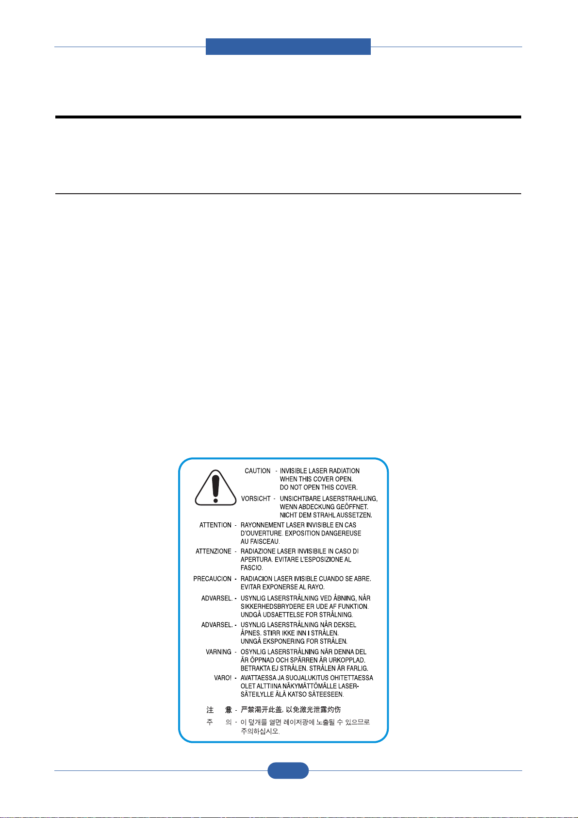
(3) Laser Safety Statement
The Printer is certified in the U.S. to conform to the requirements of DHHS 21 CFR, chapter 1 Subchapter J
for Class 1(1) laser products, and elsewhere, is certified as a Class I laser product conforming to the
requirements of IEC 825.
Class I laser products are not considered to be hazardous. The laser system and printer are designed so
there is never any human access to laser radiation above a Class I level during normal operation, user
maintenance, or prescribed service condition.
Warning >> Never operate or service the printer with the protective cover removed from Laser/Scanner assembly. The reflected
beam, although invisible, can damage your eyes. When using this product, these basic safety precautions should
always be followed to reduce risk of fire, electric shock, and injury to persons.

Service Manual
Precautions
1-2
Samsung Electronics
1.2 Safety Caution
1.2.1 Noxious Material Precaution
The toner in a printer cartridge contains a chemical material, which may harm human body if it is swallowed.
Please keep children out of reach of the toner cartridge.
1.2.2 Electric Shock or fire Precaution
It is possible to get electric shock or burn by fire if you don't fallow the instructions of the manual.
(1) Use exact voltage. Please use an exact voltage and wall socket. If not, a fire or an electric leakage can be
caused.
(2) Use authorized power cord. Do use the power cord supplied with PRINTER. A fire can happen when over cur-
rent flows in the power cord.
(3) Do not insert many cords in an outlet. A fire can be occurred due to flow over current in an outlet.
(4) Do not put water or extraneous matter in the PRINTER. Please do not put water, other liquid, pin, clip, etc. It
can cause a fire, electric shock, or malfunction. If this occurs, turn off the power and remove the power plug
from outlet immediately.
(5) Do not touch the power plug with wet hand. When servicing, remove the power plug from outlet. Do not insert
or take off it with wet hand. Electric shock can be occurr.
(6) Caution when inserting or taking off the power plug. The power plug has to be inserted completely. If not, a fire
can be caused due to poor contact. When taking off the power plug, grip the plug and take it off. If grip the line
and pull over, it could be damaged. A fire or electric shock could happen.
(7) Management of power cord. Do not bend, twist, or bind it and place other materials on it. Do not fix with sta-
ples. If the power cord gets damaged, a fire or electric shock can happen. A damaged power cord must be
replaced immediately. Do not repair the damaged part and reuse it. A repaired part with plastic tape can be
cause a fire or electric shock. Do not spread chemicals on the power cord. Do not spread insecticide on the
power cord. A fire or electric shock can be happen due to thinner(weak) cover of the power cord.
(8) Check whether the power outlet and the power plug are damaged, pressed, chopped, or blazing fire or not.
When such inferiorities are found, repair it immediately. Do not make it pressed or chopped when moving the
machine.
(9) Caution when there is thundering or lightning, and being flash of lightening. It causes a fire or electric shock.
Take the power plug off there is thunder. Do not touch cable and device when thundering and flash of lighten-
ing.
(10) Avoid the place where is moisture or has dust. Do not install the printer where lots of dust or around humidifi-
er. A fire can occurred. A plug part need to clean well with dried fabric to remove dust. If water drops are
dripped on the place covered with dust, a fire can occurred.
(11) Avoid direct sunlight. Do not install the printer near window where direct contacts to the sunlight. If the
machine contacts sunlight long time, the machine cannot work properly because inner temperature of the
machine is getting hotter. A fire can occur.
(12) Turn off the power and take off the plug when smoke, strange smell, or sound from the machine. If you keep
using it, a fire can be occurred.
(13) Do not insert steel or metal piece inside/outside of the machine. Do not put steel or metal piece into a ventila-
tor. An electric shock could happened.

Service Manual
Precautions
1-3
Samsung Electronics
1.2.3 Handling Precautions
If you ignore this information, you could harm machine and could be damaged.
(1) Do not install it on different levels, or slanted floor.
Please confirm whether it is balanced or not after installation. If it is unbalanced, an accident can be hap-
pened due to the machine falling over.
(2) Be careful not to insert a finger or hair in the rotating unit.
Be careful not to insert a finger of hair in the rotating unit (motor, fan, paper feeding part, etc) while the
machine is operating. Once it happens, you could be harmed.
(3) Do not place a pot containing water/chemical or small metals. If they got caught into the inner side of
machine, a fire or electric shock can be occurred.
(4) Do not install it where lots of moisture or dust exists or where raindrop reaches. A fire or electric shock
can be caused.
(5) Do not place a candlelight, burning cigarette, and etc. on the machine. Do not install it near to heater. A
fire can be occurred.
1.2.4 Assembly/Disassembly precaution
When replacing parts, do it very carefully. Memorize the location of each cable before replace parts for reconnecting it afterwards. Do memorize. Please perform the steps below before replace or disassembly the parts.
(1) Check the contents stored in the memory. All the information will be erased after replacing main board.
The information needed to keep has to be written down.
(2) Before servicing or replacing electric parts, take off a plug.
(3) Take off printer cables and power cord connected to printer.
(4) Do use formal parts and same standardized goods when replacing parts.Must check the product name,
part cord, rated voltage, rated current, operating temperature, etc.
(5) Do not give an over-force when release or tighten up the plastic parts.
(6) Be careful not to drop the small parts such as screws in the printer.
(7) Be careful not to change the location of small parts such as screws when assembling and disassembling.
(8) Do remove dust or foreign matters completely to prevent fire of tracking, short, or etc.
(9) After finished repair, check the assembling state whether it is same as before the repair or not.

Service Manual
Precautions
1-4
Samsung Electronics
1.3 ESD Precautions
Certain semiconductor devices can be easily damaged by static electricity. Such components are commonly called
“Electrostatically Sensitive (ES) Devices”, or ESDs. Examples of typical ESDs are: integrated circuits, some field
effect transistors, and semiconductor “chip” components.
The techniques outlined below should be followed to help reduce the incidence of component damage caused by
static electricity.
Caution >>Be sure no power is applied to the chassis or circuit, and observe all other safety precautions.
1. Immediately before handling a semiconductor component or semiconductor-equipped assembly, drain off any
electrostatic charge on your body by touching a known earth ground. Alternatively, employ a commercially available wrist strap device, which should be removed for your personal safety reasons prior to applying power to the
unit under test.
2. After removing an electrical assembly equipped with ESDs, place the assembly on a conductive surface, such
as aluminum or copper foil, or conductive foam, to prevent electrostatic charge buildup in the vicinity of the
assembly.
3. Use only a grounded tip soldering iron to solder or desolder ESDs.
4. Use only an “anti-static” solder removal device. Some solder removal devices not classified as “anti-static” can
generate electrical charges sufficient to damage ESDs.
5. Do not use Freon-propelled chemicals. When sprayed, these can generate electrical charges sufficient to dam-
age ESDs.
6. Do not remove a replacement ESD from its protective packaging until immediately before installing it. Most
replacement ESDs are packaged with all leads shorted together by conductive foam, aluminum foil, or a comparable conductive material.
7. Immediately before removing the protective shorting material from the leads of a replacement ESD, touch the
protective material to the chassis or circuit assembly into which the device will be installed.
8. Maintain continuous electrical contact between the ESD and the assembly into which it will be installed, until
completely plugged or soldered into the circuit.
9. Minimize bodily motions when handling unpackaged replacement ESDs. Normal motions, such as the brushing
together of clothing fabric and lifting one’s foot from a carpeted floor, can generate static electricity sufficient to
damage an ESD.

Service Manual
Product spec and feature
2-1
Samsung Electronics
2. Product specification and feature
2.1 Product Specifications
2.1.1 Product Overview
Item Descriptions
Model name ML-1640/ML-2240
Marketing target Personal use
Main Specification * speed
ML-1640 : 17 ppm (Ltr) / 16 ppm (A4)
ML-2240 : 23 ppm (Ltr) / 22 ppm (A4),
* 150MHz Jupiter4e CPU/ 8M memory
* Toner Cartridge : Initial (0.7K), Sales (1.5K)
* Machine Life : 50K
2.1.2 Specifications
Product Specifications are subject to change without notice. See below for product specifications.
2.1.2.1 General Specifications
Item ML-1640 ML-2240
Major Features Print Print
Size (W*D*H) 353mmx298mmx213mm 353mmx298mmx213mm
(13.9"x11.7"x8.4") (13.9"x11.7"x8.4")
Net Weight (Inc. Toner Cartridge) 5.7kg 5.9kg
Net Weight (exc. Toner Cartridge) 4.95kg 5.05kg
Gross Weight (with package) 7.1Kg 7.5Kg
LCD N/A (one button, 2 LED) N/A (one button, 2 LED)
I/O Interface USB2.0 Full-Speed USB2.0 Full-Speed
MPU Jupiter4e / 150MHz Jupiter4e / 150MHz
Power Consumption Printing Operation 300W 350W
Sleep Mode 6 Wh Energy Star Compliant 6Wh Energy Star Compliant
Power Switch Yes Yes
Power Supply Input Voltage Low Voltage : 110 ~ 127VAC Low Voltage : 110 ~ 127VAC
High Voltage : 220 ~ 240VAC High Voltage : 220 ~ 240VAC
Input Frequency 50 / 60Hz(+/- 3Hz) 50 / 60Hz(+/- 3Hz)
Noise Printing 50dBA 51dBA
Standby 26dBA 32dBA
Max. Monthly Volume Print 5000pages 10,000pages
(Duty Cycle)
Service Manual
Product spec and feature
2-2
Samsung Electronics
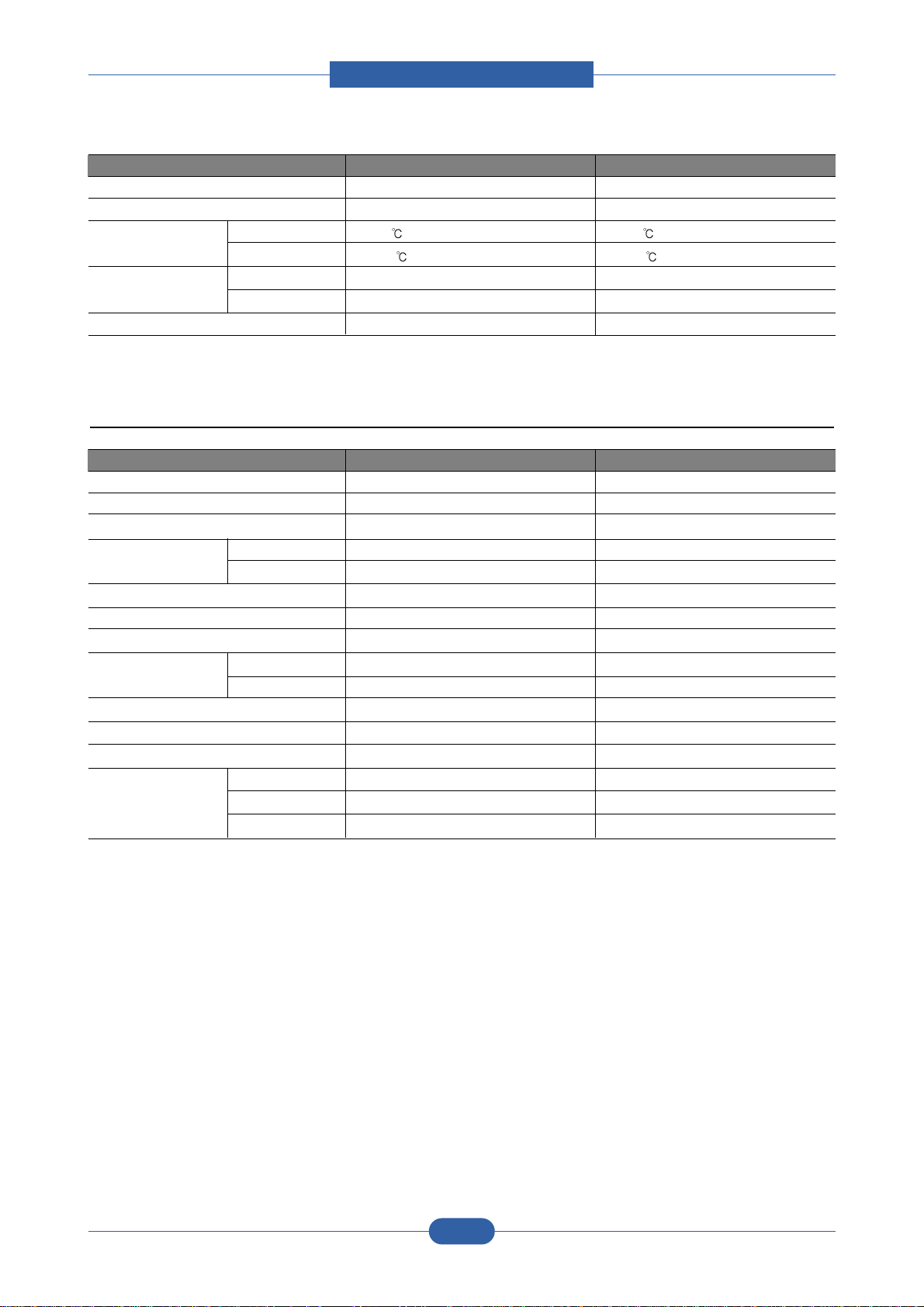
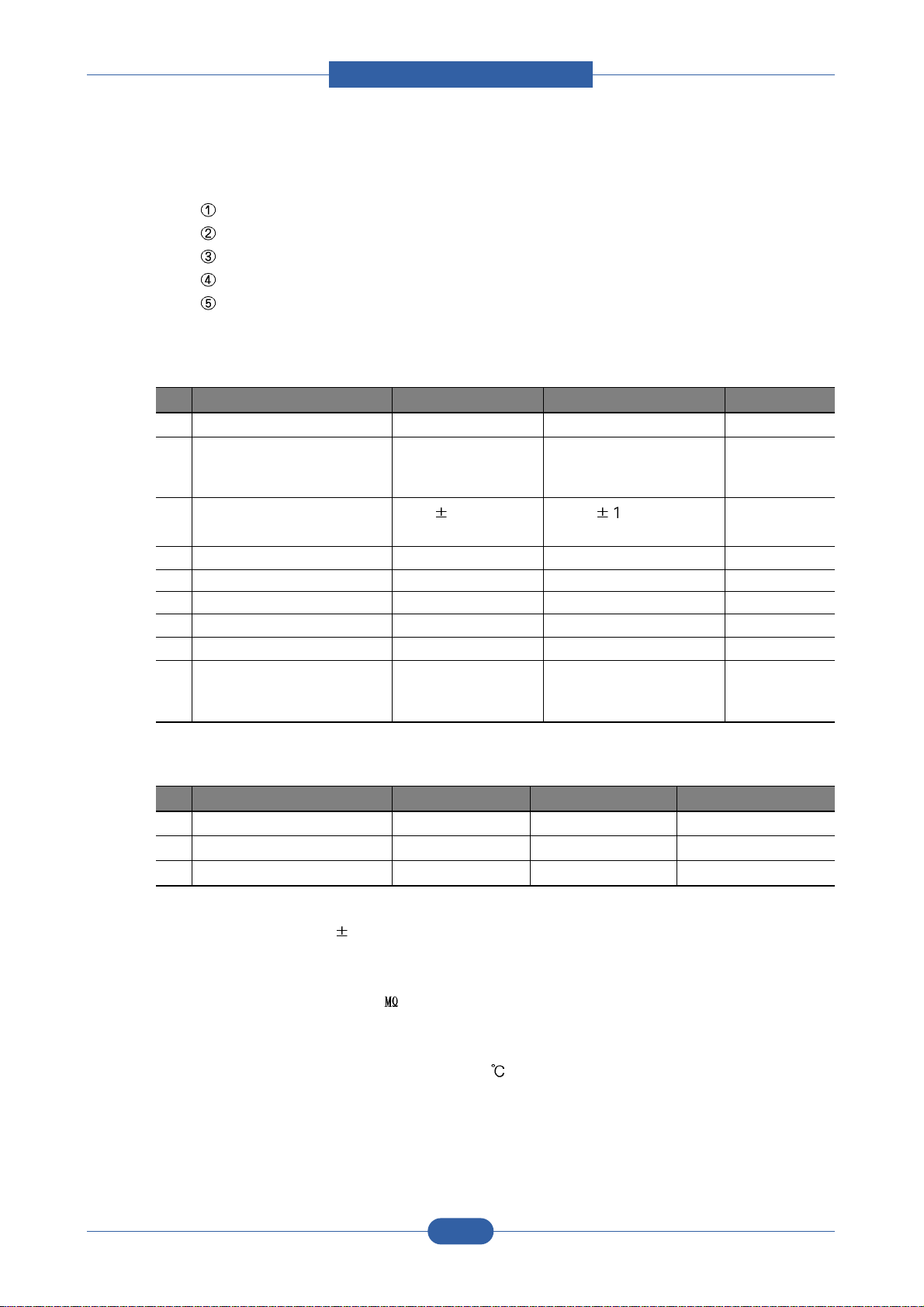
2.1.2.2 Print Engine
Item ML-1640 ML-2240
Average Monthly Print Volume 140pages 170pages
Machine Life 50,000pages 50,000pages
Temperature Operating 10~32
10~32
Non Operating -20~40 -20~40
Humidity Operating 20~80% 20~80%
Non Operating 10~90% 10~90%
Altitude Max 8,200ft Max 8,200ft
Item ML-1640 ML-2240
Print Speed 17ppm/Ltr, 16ppm/A4 (600 dpi) 23ppm/Ltr, 22ppm/A4 (600 dpi)
Print Emulation GDI, GDI,
Auto Emulation Sensing YES YES
Font Type N/A N/A
Number N/A N/A
Power Save Yes(5/10/15/20/30/45/60/120min.) Yes(5/10/15/20/30/45/60/120min.)
Resolution 600x600dpi 600x600dpi
Toner Save Yes (No dedicated button on CP) Yes (No dedicated button on CP)
FPOT From Stand by Approx. 10 seconds (From LSU 'ON', A4) Approx. 10 seconds (From LSU 'ON', A4)
From Sleep mode Less than 40 seconds Less than 19 seconds
Duplex Print N.A N.A
Printable Area 208 x 273 mm (Letter) 208 x 273 mm (Letter)
Halftone(Gray Scale) 128levels 128levels
Memory Standard / Max. 8MB/8MB(Std./Max) 8MB/8MB(Std./Max)
Type SDRAM SDRAM
Expand Memory Slot
N/A N/A
Service Manual
Product spec and feature
2-3
Samsung Electronics
2.1.2.3 Paper Handling
Item ML-1640 ML-2240
Capacity(20 lbs) Main Tray 150sheets 150sheets
Bypass N/A N/A
Optional Cassette N/A N/A
Output Capacity Face Down: 50Sheets/20lb Face Down: 100Sheets/20lb
Output Control Face down Face down
Paper Size Auto Feeding A4, Letter, Legal, Oficio, Folio, Executive, A4, Letter, Legal, Oficio, Folio, Executive,
JIS B5, ISO B5, A5, A6, JIS B5, ISO B5, A5, A6,
Envelop 10 DL C5 C6 73/4 Envelop 10 DL C5 C6 73/4
Paper Weight Auto Feeding 16~24 lb. 16~24 lb.
Manual Feeding 24~43 lb. 24~43 lb.
Paper Path Standard output Bottom to Upper Front (FIFO) Bottom to Upper Front (FIFO)
Straight Through N/A N/A
Paper Size Max 216 x 356mm(8.5"x14") 216 x 356mm(8.5"x14")
Min 76 x 127mm(3"x5") 76 x 127mm(3"x5")
Printing Skew Top 2.5/177.8mm 2.5/177.8mm
Side 3.5/241.3mm 3.5/241.3mm
Item ML-1640 ML-2240
Compatibility DOS No No
Win 3.x No No
Win 95 Yes (except Status Monitor) Yes (except Status Monitor)
Win 98 Yes Yes
Win ME Yes Yes
Win NT 4.0 Yes Yes
Win 2000 Yes Yes
Win XP Yes Yes
Mac No Yes
Linux No Yes
WHQL Printer Yes for 2000 & XP Yes for 2000 & XP
Driver Printer GDI GDI
TWAIN No No
WIA No No
RCP No None
2.1.2.4 Software

Service Manual
Product spec and feature
2-4
Samsung Electronics
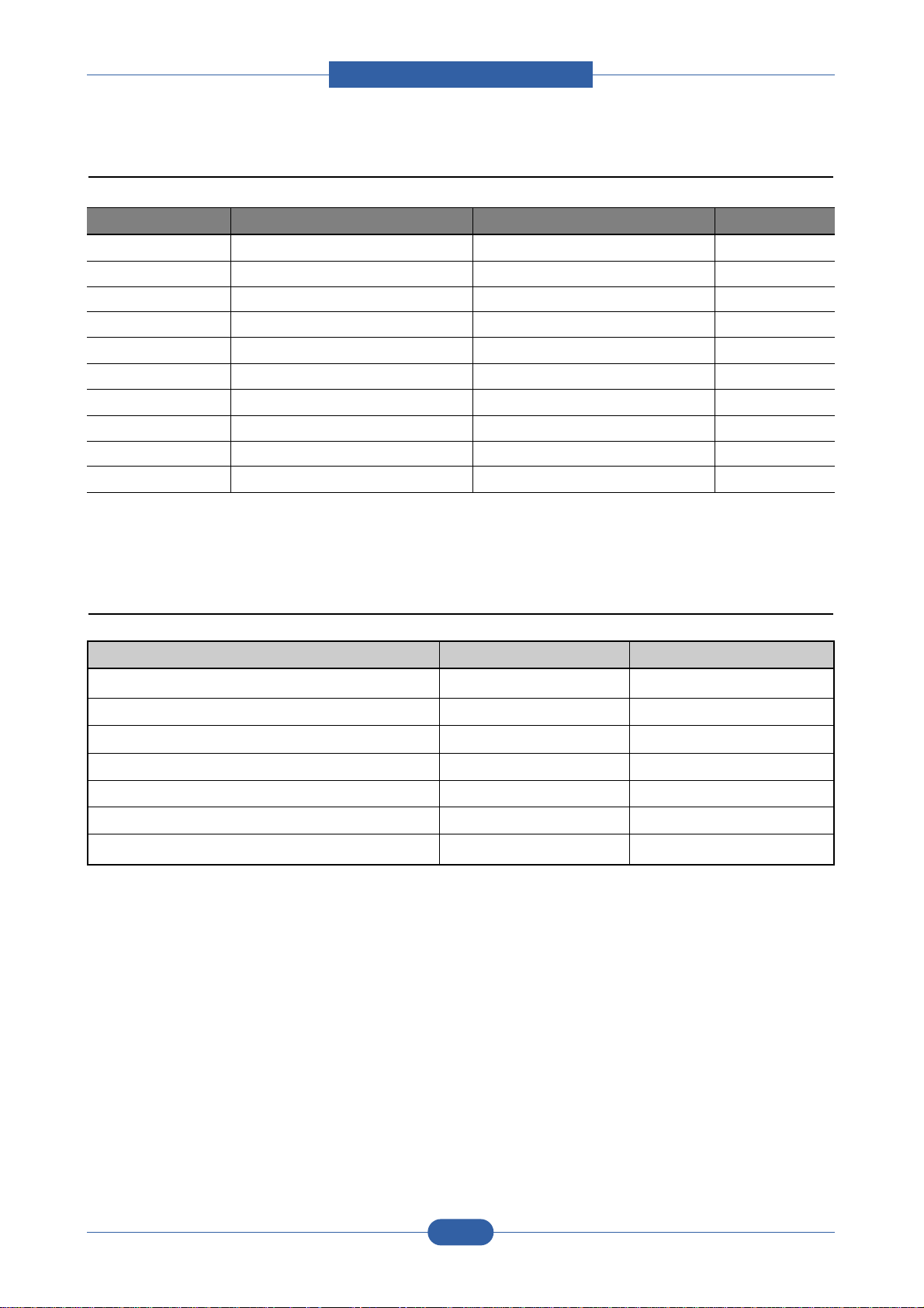
Item ML-1640 ML-2240
FRU Pickup Roller 50 K 50 K
Pad Unit 50 K 50 K
Transfer Roller 50 K 50 K
Fuser Unit 50 K 50 K
CRU Toner Life Initial : 0.7K pages Initial : 0.7K pages
Sales : 1.5K pages Sales : 1.5K pages
( ISO / IEC 19752 Standard pattern) ( ISO / IEC 19752 Standard pattern)
2.1.2.5 Consumables
Service Manual
Product spec and feature
2-5
Samsung Electronics
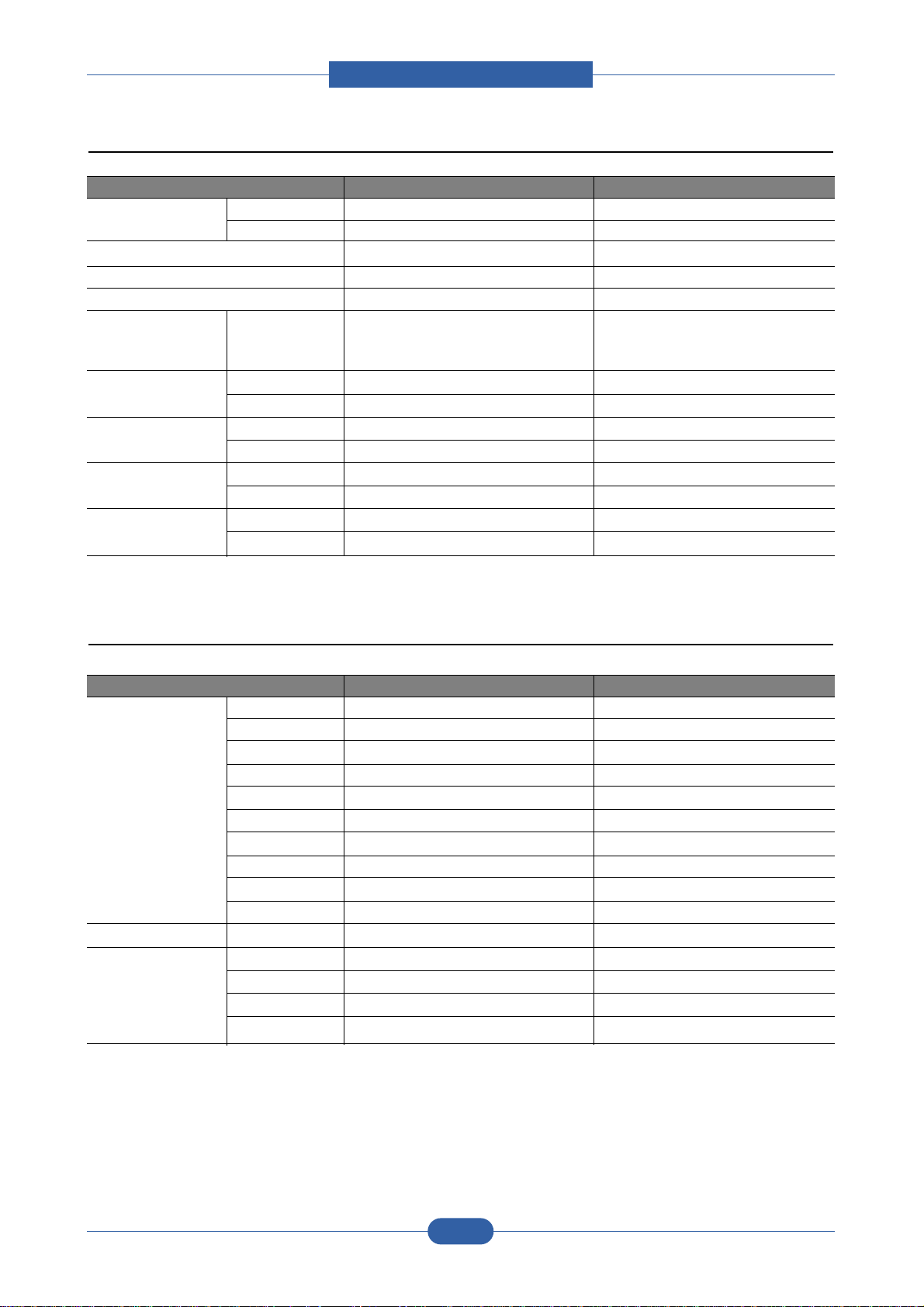
ML-1640 ML-2240 Remark
CPU Jupiter 4e Jupiter 4e same
Code Legacy Platform
PPM A4 : 16ppm / Letter : 17ppm A4 : 22ppm / Letter : 23ppm
Memory 8MB 8MB
Dev. Fuse No. (New Drum Detection : By CRUM) No. (New Drum Detection : By CRUM) same
Resolution 300 / 600dpi 600 / 1200dpi
SPL Driver Unified UI Unified UI
Manual Duplex No. Yes.
Fan No. Yes.
Mech Manual Feeder Guide : Yes
2.1.3 Model Comparison Table
2.1.4 Accessory List
Item ML-1640 ML-2240
INA-ACCESSORY JC99-02162C JC99-02161C
CBF-POWER CORD 3903-000042 3903-000042
BAG PE 6902-000809 6902-000809
S/W APPLICATION-CD JC46-00403A JC46-00402A
MANUAL-(CARD)WARRANTY CARD JC68-00690A JC68-00690A
LABEL(P)-BLANK 90*25 JC68-01584A JC68-01584A
COVER-PAPER JC63-01891A
Service Manual
Product spec and feature
2-6
Samsung Electronics
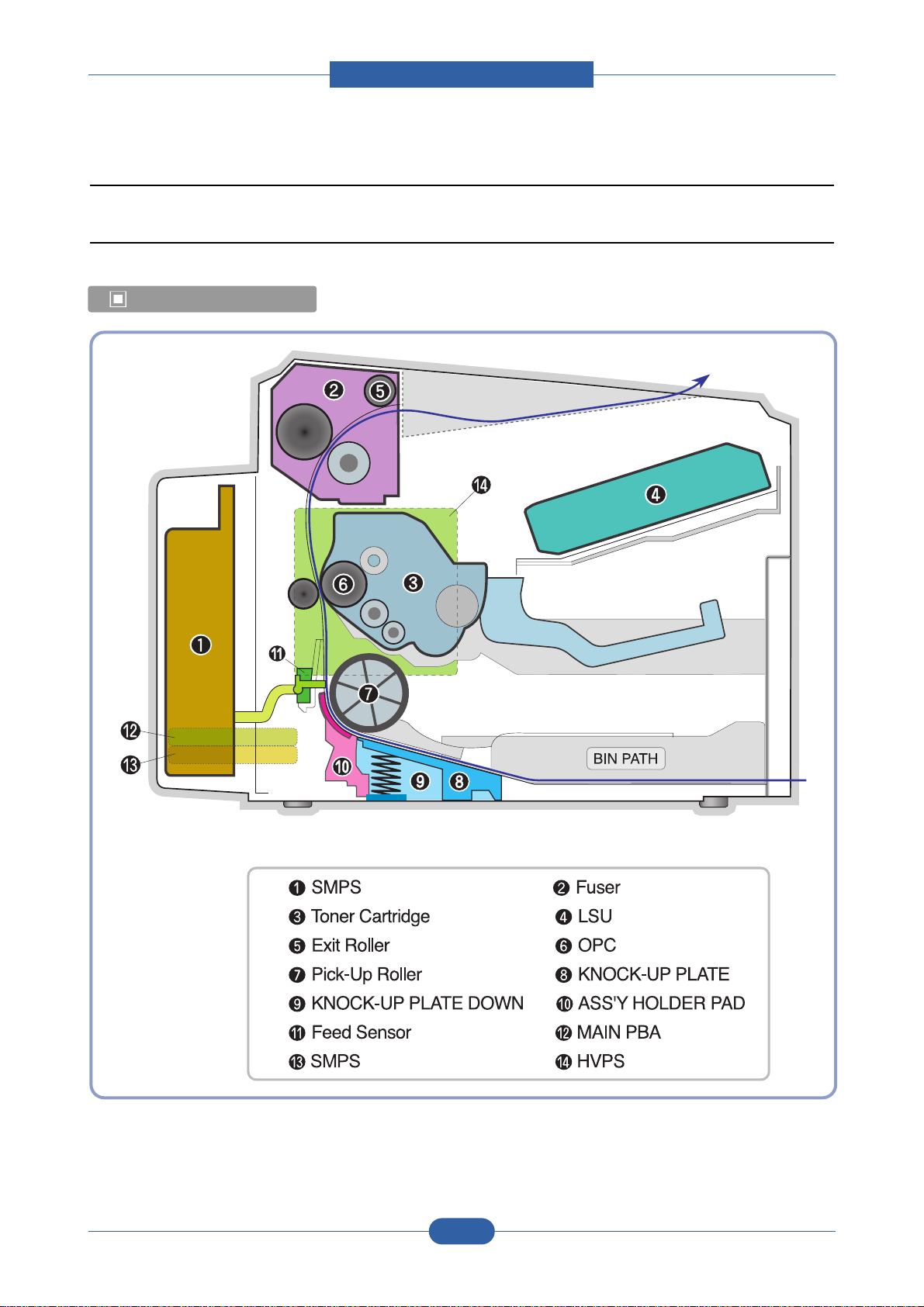
2.2 System Overview
2.2.1 System Outline
Paper Path Layout
Service Manual
Product spec and feature
2-7
Samsung Electronics
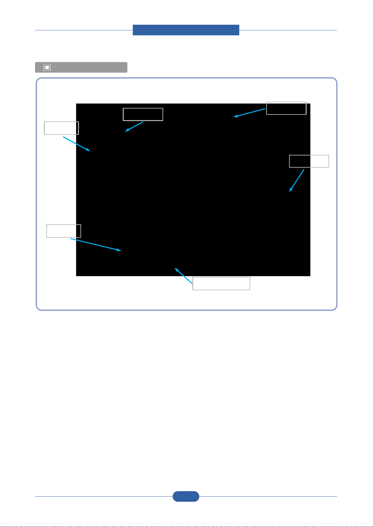
Unit Layout
HVPS
SMPS
Main PBA
Motor
LSU
Panel

Service Manual
Product spec and feature
2-8
Samsung Electronics
2.2.1.1 Feeding
There are the C-path type, which loads papers, and the manual feeder, which supplies paper one by one.The
cassette has the function pad which separates paper one by one, and it has the sensor function to check the
existence of the loading paper.
1) Feeding Type : MPF Type
2) Feeding Standard : Center Loading
3) Feeding Qty : Cassette 150 sheets (75g/ , 20lb paper standard)
4) Manual 1 sheet (Paper, OHP, Envelope etc.)
5) Separating Type : Cassette - Friction Pad Type
6) Driver Type : Driving by Gearing from Main Motor
7) Pick_up Roller Driver : Solenoid
8) Paper detecting Sensor : Photo Sensor
9) Paper Size Sensor : None
10) Paper Exit Type : Face Down
11) MP Tray : MP Cassette Type (Cener Loading)
2.2.1.2 Transfer Ass’y
The transfer roller delivers the toner of the OPC drum to the paper.
- The life span : Print over 50,000 sheets (in 16 ~30 )
2.2.1.3 Driver Ass’y
It is a power delivery unit by gearing. By driving the motor, it supplies the power to the feeding unit, the fusing unit,
and the distributing unit.(Motor drive IC : A3977)
- It is a power delivery unit by gearing : Feeder/Developer Motor Fuser/Exit
2.2.1.4 FUSER
The fuser is consisted of the Heat Lamp,Heat Roller,Pressure Roller,Thermister and Thermostat.
It adheres the toner on the paper with pressure and heat to complete the printing job.
- Life Cycle : 50K(pages)
Service Manual
Product spec and feature
2-9
Samsung Electronics
1) Heat Lamp
. Heat Lamp Terminal Shape : Terminal Single Type
. Voltage 120 V : 115 +/- 5 %
220 V : 230 +/- 5 %
. Capacity : 600 Watt (ML-1640), 750 Watt (ML-2240) +/- 5 %
. Life : 3000 Hr
2) Thermostat
. Thermostat Type : Non-Contact type THERMOSTAT
. Control Temperature : 150 5
3) Thermistor
. Thermistor Type : HF-K7006
. Temperature Resistance : 7 (180 )
. SYSTEM Temperature SETTING
- Stand by : 155 / 145 / 140 +/- 5 (~30page / 31 ~ 60page / 60page~ ) (NN. Plain)
- Printing : 175 / 170 +/- 5 (~30page / 30page ~) (NN. Plain)
- Overshoot : 200 or less
- Overheat : 220 or less
4) Heat roller
. Length : 247.5 mm
. Valid length : 222 mm
. GND Type : H/R Bearing Grounding type By SECC Fuser frame
5) Pressure roller
. Shaft
- Length : 237.5 mm
. Rubber
- Length : 222 mm
6) Paper separation method
Teflon sintered Claw System
7) Safety Relevant Facts
. Protecting device when overheating
- 1st protecting device : H/W cuts off when detecting an overheating
- 2st protecting device : S/W cuts off when detecting overheating
- 3st protecting device : Thermostat cuts off the power
. Safety device
- The power of Fuser is cut-off after front cover is open.
- The overheating safety device for customer
- The surface temperature of the Fuser Cover is under 80

Service Manual
Product spec and feature
2-10
Samsung Electronics
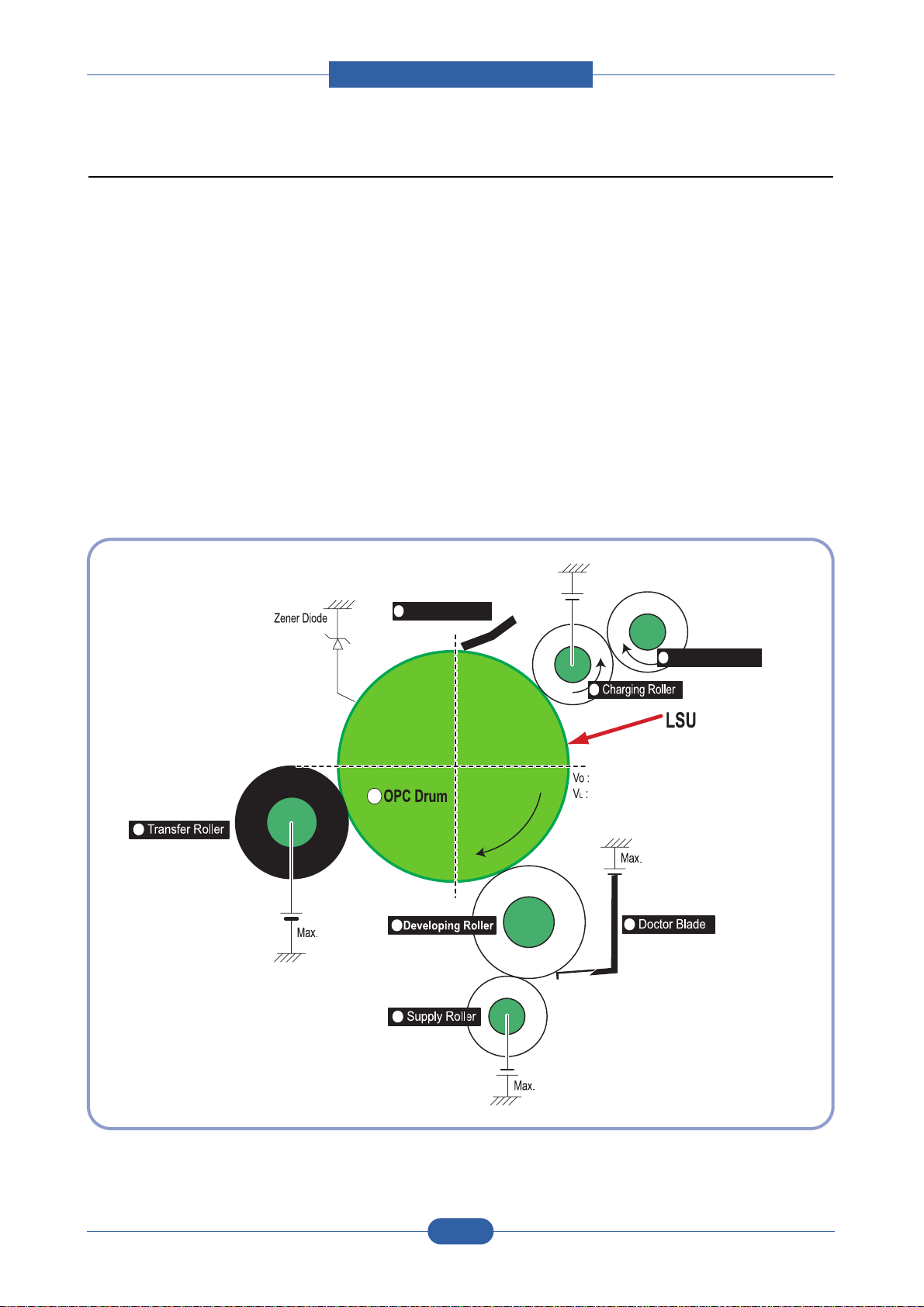
2.2.1.5 LSU (Laser Scanner Unit)
The LSU unit is controlled by video controller. It scans the video data received from video controller with laser beam
by using the rotation principle of the polygon mirror to create the latent image on the OPC drum. It is the core part of
LBP.
The OPC drum rotates as the same speed as the paper feeding speed. It creates the /HSYNC signal and sends it
to the engine when the laser beam of the LSU reaches the end of the polygon mirror, and the engine detects the
/HSYNC signal to arrange the vertical line of the image on the paper. After detecting the /HSYNC signal, the image
data is sent to the LSU to arrange the its margin on the paper. The one side of the polygon mirror is one line for
scanning..
OPC Drum
Photo Diode
LD Driver circit
Protector panel
LD(Laser Diode)
Polygon Mirror
Polygon Motor
Motor Driver
Service Manual
Product spec and feature
2-11
Samsung Electronics
Cleaning Roller
Cleaning Blade
-720V
-350V
-550V
0.20mW
Max -1.4KV
-100V
1
2
3
4
5
6
7
8
+5KV
-150V¡Ø
2.2.1.6 Toner Cartridge
By using the electronic photo process, it creates a visual image. In the toner cartridge, the OPC unit and the
developer unit are in a body. The OPC unit has OPC drum and charging roller, and the developer unit has toner,
toner cartridge, supply roller, developing roller, and blade (Doctor blade)
- Developing Method: Non magnetic 1 element contacting method
- Toner: Non magnetic 1 element shatter type toner
- The life span of toner: Initial (700 sheets) / Sales (1500 sheets) (ISO 19752 Pattern/A4 standard)
- Toner remaining amount detecting sensor: None
- OPC Cleaning: Collect the toner by using Cleaning Blade
- Management of disusable toner: Collect the toner by waste bottle
- OPC Drum protecting Shutter: None
- Classifying device for toner cartridge: ID is classified by CRUM (Toner sales)
Service Manual
Product spec and feature
2-12
Samsung Electronics
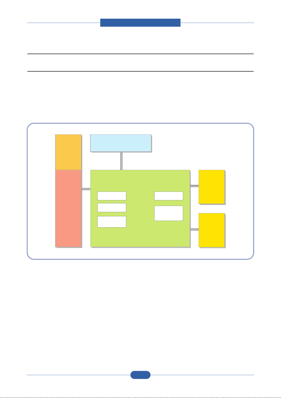
2.2.2 H/W Structure and Descriptions
2.2.2.1 H/W Overview
ML-1640/2240 is roughly made up Main Control part and SMPS/HVPS part.
Main Controller uses Jupiter4E for its ASIC, which is on chip micro controller and developed for Low-end Laser
Beam Printer.
Jupter4E provides the integrated printing functions such as Printer video controller, Laser Scan Unit controller,
PWM controller and Bi-polar Stepper Motor Controller and has USB interface and built-in Flash memory with 4Mbits
capacity.
2.2.2.1(a) Main Control
ML-1640/2240 of Main Control are composed of CPU and Print and operate follows function by CPU
- Bus Control, I/o
- Handling, each Driver and PC Interface
Main Control operate its full function on the Main B'd and CPU control Controller ASIC and build-in
Memory.
2.2.2.1(b) CPU
Use 32Bit RISC Processor of Jupiter4e, and control system by operating Operation Block of the System
Program inside Flash Memory.
SMPS
HVPS
Jupiter IV ASIC V1.1 USB
Printer
Engine
B'D
DRAM 8M Byte
Flash Memory
0.5M Byte
OPE B'D
(Build-in HVPS)
Main Controller
LSU
Motor

Service Manual
Product spec and feature
2-13
Samsung Electronics
- Main Function Block: Completely Integrated System for Embedded Applications,
32 Bit Risc Architecture, Efficient and Powerful ARM9 CPU
LSU Interface Module for Interfacing PVC with LSU
2 Channel General Purpose DMA Controller for High Speed I/O
Dual Memory Bus Architecture
- Operation Frequency : 150MHz
- Operation Voltage : 3.3V
- POWER ON RESET TIME : 6.6ms below
2.2.2.1(c) Flash Memory
Store System Program and can be down load System Program through PC Interface
- Capacity : 0.5M Byte
- Access Time : 70 nsec
2.2.2.1(d) DRAM
When Printing, use Band Buffer, System Working Memory Area .
- 8M capa : 8M Byte basic.
- Access Time : 60 nsec
2.2.2.1(e) ENGINE
This recording method is electrophography method using LSU, which toner is composed of 1 component
and non magnetic.
1) Recording Method : LSU(Laser Scanning Unit)
2) Printing Speed : 22ppm
(In continuing printing base A4, printing pages from 2nd to last during 1min)
3) Recording Density : 600 dpi 1200 dpi
4) Cassette Capa. : Cassette ; 150sheets(75g Base),
Manual : 1 sheet (Paper, OHP, Envelop, etc )
5) Paper Size : Cassette ,Manual; Width = 76 ~ 216mm, Length = 125mm ~ 356mm
6) Effective recording size
- A4 : 202 x 291 mm
- Letter : 208 x 273 mm
- Legal : 208 x 350 mm
- Folio : 208 x 325 mm
- Top Margin : 4.23 3 mm
- Left, Right Margin : 4.23 3 mm
7) CRU(Toner Cartridge)Life : 1,500pages Printing(A4, 5% Pattern Printing)
8) First Print Out Time : 10sec( Standby )
Service Manual
Product spec and feature
2-14
Samsung Electronics
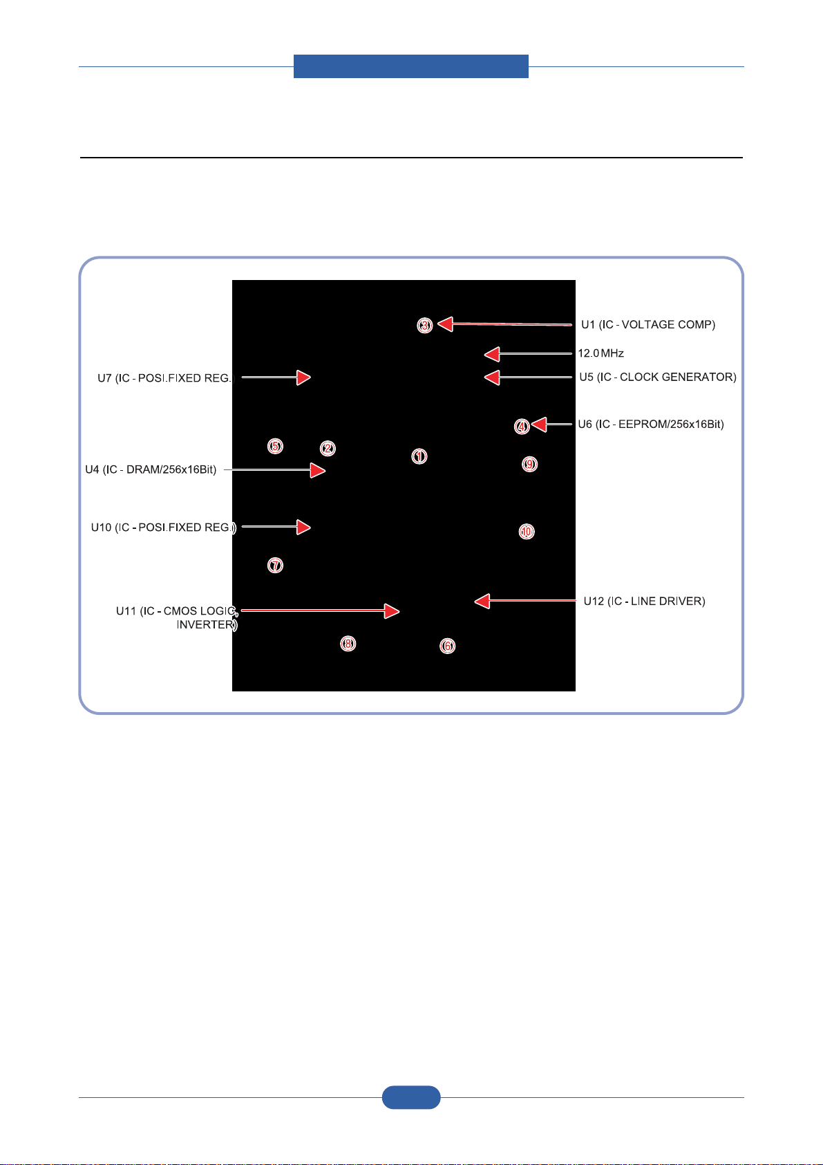
2.2.2.2 Main Board
Main Board are composed of Engine and Controller on the one-Board.
Main Board control to send Current Imagedml Video Data to LSU to print and have motor Driving and Circuit for the
current driving and also include Paper Exit Sensor, Cover Open s/w, panel s/w.

Service Manual
Product spec and feature
2-15
Samsung Electronics
U6(Jupiter 4E)
- It is a main CPU and an Asic of Jupiter4E which has a CPU core CLK with over 150MHz and a System bus 75MHz.
- It use 3.3V for operation voltage and I/O, It uses 75MHz for system bus CLK, Built in Flash Memory.
SDRAM
- Main memory. SDCLK is 75Mhz.
Regulator
- It Supplies the core voltage to CPU by converting 3.3V to 1.8V.
EEPROM(U8 : 93C66)
- It is an EEPROM with 12C method.
SMPS connector(CN7)
- It connects SMPS, supplies the power, and delivers the high voltage contol signal, etc. If a harness is not normally
connected to this connector, power cannot be supplied.
LSU connector(CN14)
- It connects a LSU.
BLDC Motor connector(CN9)
- It connects an main motor and drive a BLDC Motor.
HVPS connector(CN13)
- It connects a HVPS.
DCU connector(CN8)
- It interface a DCU-JIG
USB connector(CN10)
- It interface a the printer.

Service Manual
Product spec and feature
2-16
Samsung Electronics
2.2.2.3 Asic(SPGPm) Specification
2.2.2.3(a) Introduction
Jupiter4E is One-Chip micro-Controller for Low cust Laser beam Printer.
1. One Chip Laser Beam Printer Controller
- GDI only
- AMBA AHB used for high speed bus transactions between masters and slaves
- AMBA APB used for low speed bus transactions between ARM core and peripherals
- 3 PLLs ( 2 Dithered PLL and 1 General PLL)
first for CPU(150MHz), AHB(75MHz), APB(75MHz),
second for USB(48MHz)
third for PVC(59MHz)
- 75MHz system operation
- 1.8V power operation
- 3.3V tolerant input and bi-directional I/Os
- SDRAM and IO Address / Data signals multiplexing
2. Integrated ARM940T 32-bit RISC embedded processor core
- 150MHz core frequency operation
- Harvard Architecture Cache : 4KByte Instruction cache, 4KByte Data cache
- Single memory bus architecture
3. Built in Flash Memory
- 4MBits (128Kx32bits)
- Serial programming mode using flash programmer tool
- Internally flash memory read / write operation support
- Programmable access timing control
4. 32MB Special function Register Area
5. Directly connected to 3 external IO banks (IOC)
- 32 MB size in each IO bank
- Programmable setup, access, hold timing
- Programmable recovery time for slow devices
- Allows to access peripheral devices such as GPIO control logic
6. Directly connected to 1 external ROM bank (ROMC)
- 32 MB size for one ROM bank
- One external flash memory attachable.

Service Manual
Product spec and feature
2-17
Samsung Electronics
7. Directly connected to two SDRAM banks (SDRAMC)
- Extensible architecture
- Two external SDRAM attachable.
- SDRAM controller supports PC-100 and PC-133 SDRAM running at 75MHz
- Up to 32MB per bank.
- Support for SDRAM configurations including programmable column address
- Programmable refresh interval
8. Interrupt Controller (INTC)
- FIQ or IRQ mode operation selectable
- Programmable Interrupt Enable/Disable
9. USB interface
- Version 1.1
- Four 128x8 FIFOs for Data transmission.
- Interrupt based input / output interface, no DMA based interface support
- USB wrapper for AHB interface
- AHB Bus interface
10. Serial port interface (UART)
- Programmable Baud Rate
- 2 channel Independent Full Duplex UART
- Polling, Interrupt based operation support
- Max 16 byte FIFO to handle SIR Bit Rate Speed
11. Printer video controller for LBP engines (PVC)
- 80MHz video rate (Hummingbird 2 : letter - 21 ppm, A4 : 20ppm)
- video data transmitted through LSU Controller
12. Laser Scan Unit (LSU) Controller
- Laser Scan Unit (LSU) Interface for Laser Diode turn on/off timing control
- Sample & hold period generation.
- Auto Power Control for Laser Diode with PID control method using internal 10 bits DAC.
- LSU clock generation
- Brushless DC motor control clock generation
13. ADC Interface
- 4 channels ADC interface for analog devices such as temperature sensor.
- Programmable ADC Clock Cycle.
- Automatic or Manual AD Conversion support.
- 4 Special Function Registers for monitoring the ADC results for 4 channels.

Service Manual
Product spec and feature
2-18
Samsung Electronics
14. PWM Controller
- 4 PWM output ports - THV, BIAS, FAN control and AC ELECTRIFICATION
15. Bi-polar Stepper Motor controller (MOTORC)
- Phase generation for the purpose of paper feeding
- fixed hardware phase and current table
- programmable phase and interval time
- Interrupt based phase change operation
16. Timer
- 3 Independent Programmable Timers
- Watch Dog Timer for S/W Trap
17. Miscellaneous
- Mux controlled 24 GPI, 28 GPO & 5 GPIO ports .
- Mutual exclusive GPO/GPIO ports control by the port control enable register
- Programmable Bus Master Priority.
- Project code added.

Service Manual
Product spec and feature
2-19
Samsung Electronics
2.2.2.4 Sensor Controller
2.2.2.4(a) Paper Feeding/Width
When a paper passes an actuator of a feed sensor unit after feeding a paper into a set,it detects a signal of
the photo interrupter and informs the paper feeding status to CPU. After sensing the signal and certain time
later, it strews an image data.(Related in Paper Front Edge Adjustment)
If it could not detect the feed sensor within 1 second after feeding a paper, a paper jam0 (CPU#_) occurs.
2.2.2.4(b) Paper Empty Sensing
The paper empty is detected by the empty sensor mounted to an engine board and the actuator mounted
to a frame. Paper senses the on/off time of the empty sensor by using CPU and informs the normal
operation status and the jam occurrence status to CPU.
2.2.2.4(c) Jam Cover/Cover Open Sensing
ML-1640/2240 uses two M/S:one senses the cover open and the other senses the jam cover open.
The cover open sensor is located on the left bottom of HVPS.When the front cover is open, +24V supplied
to each unit (DC fan, Solenoid, Main Motor, Polygon Motor Unit of LSU in Fusing Unit, and HVPS) is
interrupted.
The jam cover open sensor is located on the centeral top of HVPS. When the jam cover is open, +24V
supplied to each unit (DC fan, Solenoid, Main Motor, Polygon Motor Unit of LSU in Fusing Unit, and HVPS)
is interrupted.
D0 bit of CPU detects the jam cover open/cover open, and D7 bit of CPU detects the existence of OPC.
In this case, it informs the status to user by turning on the red LED among OP panel LEDs.
2.2.2.4(d) Solenoid Driving Circuit
The solenoid consists of two used for paper pick-up and MP signal. D4 bit of CPU turns it on/off, and its
driving time is 300ms. The diode protects the drive TR from the pulse (noise)generated by de-energizing
operation of solenoid.

Service Manual
Product spec and feature
2-20
Samsung Electronics
2.2.2.5 SMPS board (Switching Module Power Supply)
The SMPS supplies DC Power to the System.
It takes 110V/220V and outputs the +5V, +24V to supply the power to the main board and other board. It is
consisted of the AMPS part, which supplies the DC power for driving the system, and the AC heater control part,
which supplies the power to fuser. SMPS has two output channels. Which are 5V and +24V
Pin No Pin Name
1 +24VS2
2 +24V
3 +24VS1
4 +24VS1
5 +5V
6 DGND
7 DGND
8 P_REGI
9 FUSER ON
<CON2>
Pin Signal
CON1(Inlet)
Micro Switch
CON2
(Output)
Exit Sensor
F1(Fuse/250V, 5A)
Power Switch
Service Manual
Product spec and feature
2-21
Samsung Electronics
1) SMPS Specification
- AC Input
Input Rated Voltage : AC 220V ~ 240V, AC 120V / AC 220V(110V version)
Input Voltage fluctuating range : AC 90V ~ 135V / AC 180V ~ 270V(220V version)
Rated Frequency : 50/60 Hz
Frequency Fluctuating range : 47 ~ 63 Hz
Input Current : Under 4.0Arms / 2.5Arms
(But, the status when lamp is off or rated voltage is inputted/outputted )
- Rated Output Power
- Consumption Power
- Power Cord Length : 1830° 50mm
- Power Cord Switch : Use
- Feature
. Insulating Resistance : 100 or more (at DC 500V)
. Insulating revisiting pressure : Must be no problem within 1 min. (at 1000Vac,10mA)
. Leaking Current : under 3.5mA
. Running Current : under 40A PEAK (AT 25 , COLD START)
under 50A PEAK (In other conditions)
. Rising Time : within 2Sec
. Falling Time : over 20ms
. Surge : Ring Wave 6KV-500A (Normal, Common)
No Items CH1 CH2 Remarks
1 Channel +5V +24.0V
2 Connector pin CON 3 CON 3
5V PIN : 11, 12 24V PIN : 2, 3, 4
GND PIN : 8, 9 GND PIN : 6, 7
3 Rated Output +5V 5% +24V 5%
(4.75 ~ 5.25V) (20.4 ~ 27.6V)
4 Max. Output current 0.8A 2.0A
5 Peak Loading current 1.0A 2.5A 1ms
6 RIPPLE NOISE Voltage 100mVp-p or less 500mVp-p or less
7 Maximum output 4W 24W
8 Peak output 5W 48W 1ms
9 Protecttion for loading
shorage and overflowing
current
No Items CH1(+5V) CH2(+24V) System
1 Stand-by 1.0 A 0.4 A AVG : 55 Wh
2 PRINTING 1.0 A 2.0 A AVG : 250 Wh
3 Sleep-Mode 0.8 A 0.4 A AVG : 10 Wh
 Loading...