

Samsung LTN1535X-XAC User Manual
BN68-00501A-00
LTN 1535
LTN 1735
00.cover 5/29/03 11:12 AM Page 1
SAFETY 1
Important
Safety Instructions
1) Read these instructions.
2) Keep these instructions.
3) Heed all warnings.
4) Follow all instructions.
5) Do not use this apparatus near water.
6) Clean only with dry cloth.
7) Do not block any ventilation openings, Install in accordance with the manufacturer’s
instructions.
8) Do not install near any heat sources such as radiators, heat registers, or other apparatus
(including amplifiers) that produce heat.
9) Do not defeat the safety purpose of the polarized or grounding-type plug. Apolarized plug
has two blades with one wider than the other. Agrounding type plug has two blades and a
third grounding prong. The wide blade or the third prong are provided for your safety.
If the provided plug does not fit into your outlet, consult an elec trician for replacement of
the obsolete outlet.
10) Protect the power cord from being walked on or pinched particu
larly at plugs, convenience receptacles, and the point where they
exit from the apparatus.
11) Only use attachments/accessories specified by the manufacturer.
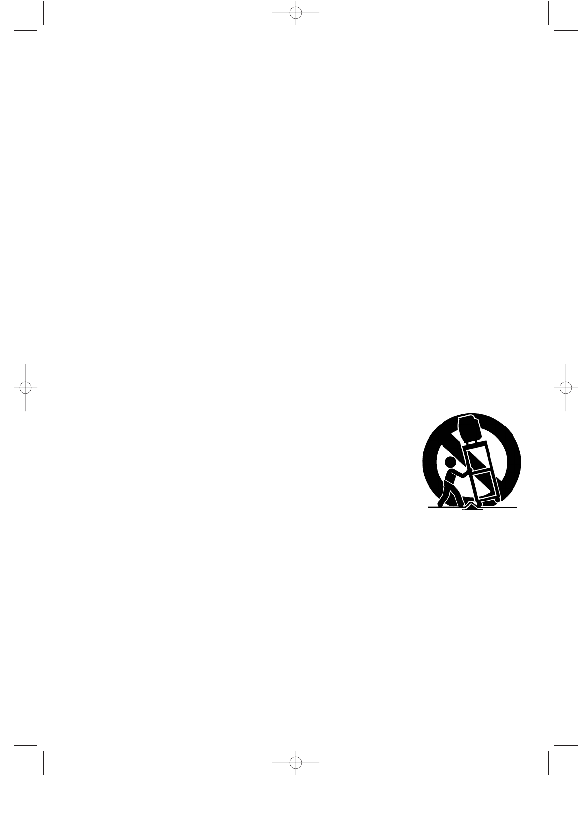
12) Use only with cart, stand, tripod, bracket, or table specified by
the manufacturer, or sold with the apparatus. When a used, cau
tion when moving the cart/apparatus combination to avoid injury
from tip-over.
13) Unplug this apparatus during lightning storms or when unused
for long periods of time.
14) Refer all servicing to qualified service personnel. Servicing is required when the apparatus
has been damaged in any way, such as power-supply cord or plug is damaged, liquid has
been spilled or objects have fallen into the apparatus, the apparatus has been exposed
to rain or moisture, does not operate normally, or has been dropped.
00.Safety+Contents 5/27/03 8:31 PM Page 1
Note to CATV system installer: This reminder is provided to call CATVsystem
installer’s attention to Article 820-40 of the National Electrical Code (Section 54 of
Canadian Electrical Code, Part I), that provides guidelines for proper grounding and,
in particular, specifies that the cable ground shall be connected to the grounding
system of the building as close to the point of cable entry as practical.
Caution: FCC/CSA regulations state that any unauthorized changes or modifications
to this equipment may void the user’s authority to operate it.
Caution: To prevent electric shock, match the wide blade of plug to the wide slot, and
fully insert the plug.
Attention: pour eviter les chocs electriques, introduire la lame le plus large de la
fiche dans la borne correspondante de la prise et pousser jusqu’au fond.
Important: One Federal Court has held that unauthorized recording of
copyrighted TV programs is an infringement of U.S. copyright laws.
Certain Canadian programs may also be copyrighted and any unauthorized recording
in whole or in part may be in violation of these rights.
To prevent damage which may result in fire or electric shock
hazard, do not expose this appliance to rain or moisture.
As an ENERGY STAR Partner.
Samsung Electronics America, Inc. has determined that this product or product
model meets the ENERGY STAR guidelines for energy efficiency.
2 SAFETY
CAUTION
CAUTION: TO REDUCE THE RISK OF ELEC
TRIC SHOCK, DO NOT REMOVE COVER
(OR BACK). NO USER SERVICEABLE PARTS
INSIDE. REFER SERVICING TO QUALIFIED
SERVICE PERSONNEL.
This symbol indicates high voltage is
present inside. It is dangerous to make
any kind of contact with any inside part
of this product.
This symbol alerts you that important
literature concerning operation and
maintenance has been included with this
product.
RISK OF ELECTRIC SHOCK DO NOT OPEN
00.Safety+Contents 5/27/03 8:31 PM Page 2

SAFETY 3
User Information
Changes or modifications not expressly
approved by the party responsible for
compliance could void the user’s authority
to operate the equipment. If necessary,
consult your dealer or an experi-enced
radio/television technician for additional
suggestions.
You may find the booklet called How to
Identify and Resolve Radio/TV
Interference Problems helpful. This booklet
was prepared by the Federal
Communications Commission.
It is available from the U.S. Government
Printing Office, Washington, DC 20402,
Stock Number 004-000-00345-4 .
Warning
In a domestic environ-ment this product
may cause radio interference in which
case the user may be required to take
ade-quate measures.
User must use shielded signal interface
cables to maintain FCC compliance for the
product.
This device complies with Part 15 of the
FCC Rules. Operation is subject to the
fol-lowing
two conditions:
(1) this device may not cause harmful
interference, and
(2) this device must accept any interfer
ence received, including interference
that may cause undesired operation.
The party responsible for product
compliance:
SAMSUNG ELECTRONICS CO., LTD
America QA Lab of Samsung
3351 Michelson Drive, Suite #290,
Irvine, CA 92612, U.S.A
Tel ) 949-975-7310
Fax) 949-975-7328
Provided with this TV is a detachable
power supply cord with IEC320 style
terminations.
For 110 Volt applications, use only UL
Listed detachable power cord with NEMA
configuration 5-15P type (parallel blades)
plug cap. For 230 Volt applications use
only UL Listed Detachable power supply
cord with NEMA configuration 6015P type
(tandem blades) plug cap.
FCC captioning
This television receiver provides display
of television closed captioning in accorda
nce with Section 15.119 of the FCC rules.
FCC Information
00.Safety+Contents 5/27/03 8:31 PM Page 3
1 CONTENTS
CONTENTS
Chapter 1: Your New TV
List of Features . . . . . . . . . . . . . . . . . . . . . . . . . . . . . . . . . . . . . . . . . . . .1
List of Parts . . . . . . . . . . . . . . . . . . . . . . . . . . . . . . . . . . . . . . . . . . . . . . .1
Familiarizing Yourself with Your New TV . . . . . . . . . . . . . . . . . . . . . . .2
Top Buttons . . . . . . . . . . . . . . . . . . . . . . . . . . . . . . . . . . . . . . . .2
Rear Panel Jacks . . . . . . . . . . . . . . . . . . . . . . . . . . . . . . . . . . . .3
Remote Control . . . . . . . . . . . . . . . . . . . . . . . . . . . . . . . . . . . . .4
Installing Batteries in the Remote Control . . . . . . . . . . . . . . . .5
Chapter 2: Installation
Connecting VHF and UHF Antennas . . . . . . . . . . . . . . . . . . . . . . . . . . .6
Antennas with 300-ohm Flat Twin Leads . . . . . . . . . . . . . . . . .6
Antennas with 75-ohm Round Leads . . . . . . . . . . . . . . . . . . . .7
Separate VHF and UHF Antennas . . . . . . . . . . . . . . . . . . . . . .7
Connecting Cable TV . . . . . . . . . . . . . . . . . . . . . . . . . . . . . . . . . . . . . . .7
Cable without a Cable Box . . . . . . . . . . . . . . . . . . . . . . . . . . . .7
Connecting to a Cable Box that Descrambles All Channels . . .7
Connecting to a Cable Box that
Descrambles Some Channels . . . . . . . . . . . . . . . . . . . . . . . . . .9
Connecting a VCR . . . . . . . . . . . . . . . . . . . . . . . . . . . . . . . . . . . . . . . . .10
Connecting an S-VHS VCR . . . . . . . . . . . . . . . . . . . . . . . . . .11
Connecting a DVD Player . . . . . . . . . . . . . . . . . . . . . . . . . . . . . . . . . . .12
Chapter 3: Special Features
Turning the TVOn and Off . . . . . . . . . . . . . . . . . . . . . . . . . . . . . . . . . .13
Changing Channels . . . . . . . . . . . . . . . . . . . . . . . . . . . . . . . . . . . . . . . .13
Adjusting the Volume . . . . . . . . . . . . . . . . . . . . . . . . . . . . . . . . . . . . . .14
Viewing the Display . . . . . . . . . . . . . . . . . . . . . . . . . . . . . . . . . . . . . . .14
Chapter 4: Operation
Plug & Play Feature . . . . . . . . . . . . . . . . . . . . . . . . . . . . . . . . . . . . . . . .15
Memorizing the Channels . . . . . . . . . . . . . . . . . . . . . . . . . . . . . . . . . . .16
Selecting the Video Signal-source . . . . . . . . . . . . . . . . . . . . .16
Storing Channels in Memory (Automatic Method) . . . . . . . .17
Adding and Erasing Channels (Manual Method) . . . . . . . . . .18
To Select TV/Input . . . . . . . . . . . . . . . . . . . . . . . . . . . . . . . . . . . . . . . .18
To Edit the Input Source Name . . . . . . . . . . . . . . . . . . . . . . . . . . . . . . .19
Using Automatic Picture Settings . . . . . . . . . . . . . . . . . . . . . . . . . . . . .20
Customizing the Picture . . . . . . . . . . . . . . . . . . . . . . . . . . . . . . . . . . . .21
Using Automatic Sound Settings . . . . . . . . . . . . . . . . . . . . . . . . . . . . . .22
Selecting a Menu Language . . . . . . . . . . . . . . . . . . . . . . . . . . . . . . . . .23
Setting the Blue Screen Mode . . . . . . . . . . . . . . . . . . . . . . . . . . . . . . . .24
00.Safety+Contents 5/27/03 8:31 PM Page 4
CONTENTS 2
CONTENTS
Fine Tuning Channels . . . . . . . . . . . . . . . . . . . . . . . . . . . . . . . . . . . . . .25
Changing the Screen Size . . . . . . . . . . . . . . . . . . . . . . . . . . . . . . . . . . .26
Freezing the Picture . . . . . . . . . . . . . . . . . . . . . . . . . . . . . . . . . . . . . . . .26
Adjusting the Background Color . . . . . . . . . . . . . . . . . . . . . . . . . . . . . .27
To select the Sound option. . . . . . . . . . . . . . . . . . . . . . . . . . . . . . . . . . .28
Setting the Clock . . . . . . . . . . . . . . . . . . . . . . . . . . . . . . . . . . . . . . . . .29
Setting the On/Off Timer . . . . . . . . . . . . . . . . . . . . . . . . . . . . . . . . . . .30
Setting the Sleep Timer . . . . . . . . . . . . . . . . . . . . . . . . . . . . . . . . . . . .32
Using the V-Chip . . . . . . . . . . . . . . . . . . . . . . . . . . . . . . . . . . . . . . . . . .33
Setting Up Your Personal ID Number (PIN) . . . . . . . . . . . . .33
How to Enable/Disable the V-Chip . . . . . . . . . . . . . . . . . . . . .34
How to Set up Restrictions Using the “TV guidelines” . . . . .34
How to Set up Restrictions using the MPAA Ratings:
G, PG, PG-13, R, NC-17, X . . . . . . . . . . . . . . . . . . . . . . . . . .36
How to Reset the TV after the V-Chip
Blocks a Channel (“Emergency Escape”) . . . . . . . . . . . . . . .37
Chapter 5: Troubleshooting
Identifying Problems . . . . . . . . . . . . . . . . . . . . . . . . . . . . . . . . . . . . . . .38
Appendix
Installing VESAcompliant mounting devices . . . . . . . . . . . . . . . . . . . .39
Attaching a Wall or Arm mounting device . . . . . . . . . . . . . . . . . . . . . .40
Using the Anti-Theft Kensington Lock . . . . . . . . . . . . . . . . . . . . . . . .41
Retractable Stand . . . . . . . . . . . . . . . . . . . . . . . . . . . . . . . . . . . . . . . . . .41
Cleaning and Maintaining Your TV . . . . . . . . . . . . . . . . . . . . . . . . . . .42
Specifications . . . . . . . . . . . . . . . . . . . . . . . . . . . . . . . . . . . . . . . . . . . .43
00.Safety+Contents 5/27/03 8:31 PM Page 5
English-1
List of Features
Your TV was designed with the latest technology. This TV is a high-performance unit
that includes the following special features:
• Easy-to-use remote control
• Easy-to-use on-screen menu system
• Automatic timer to turn the TV on and off
• Adjustable picture and sound settings that can be stored in the TV’s memory
• Automatic channel tuning for up to 181 channels
• Aspecial filter to reduce or eliminate reception problems
• Fine tuning control for the sharpest picture possible
• Abuilt-in multi-channel sound decoder for stereo and bilingual listening
• Built-in, dual channel speakers
• Headphone jack for private listening
List of Parts
Please make sure the following items are included with your LCD TV.
If any items are missing, contact your dealer.
Chapter One
YOUR NEW TV
Remote Control
(BN59-00376B) &
Batteries (AAA x 2)
4301-000121
Owner’s
Instructions
POWER CORD
(BH39-10339X)
01-12 5/30/03 10:40 AM Page 1
English-2
Familiarizing Yourself with The TV
Top Buttons
The buttons on the top panel control your TV’s basic features, including the on-screen menu.
To use the more advanced features, you must use the remote control.
YOUR NEW TV
TV/VIDEO
Displays a menu of all of the available
input sources ( TV, VIDEO, S-VIDEO,
Component ).
MENU
Press to see an on-screen menu of
your TV’s features.
– VOL +
Press to increase or decrease the volume.
Also used to select items on the
on-screen menu.
CH
Press to change channels.
Also press to highlight various items
on the on-screen menu.
Power
Press to turn the TV on and off.
SPEAKER
Remote Control Sensor
Aim the remote control towards this spot
on the TV.
Power Indicator
Lights up when you turn the power off.
01-12 5/30/03 10:40 AM Page 2
English-3
YOUR NEW TV
Rear Panel Jacks
Use the rear panel jacks to connect an A/V component that will be connected
continuously, such as a VCR or a DVD player.
For more information on connecting equipment, see pages 6-12.
POWER INPUT
VIDEO INPUT
Connect a video signal from a
camcorder or VCR.
AUDIO INPUT
Connect audio signal from a
camcorder or VCR.
SUPER VIDEO INPUT
Connect S-Video signal from a
camcorder or VCR.
TV ANTENNA
Connect to an antenna or to a cable
TV system.
COMPONENT
Connect component video/audio from
a DVD player.(only 480i)
WALL MOUNT HOLES
KENSINGTON LOCK
01-12 5/30/03 10:40 AM Page 3
English-4
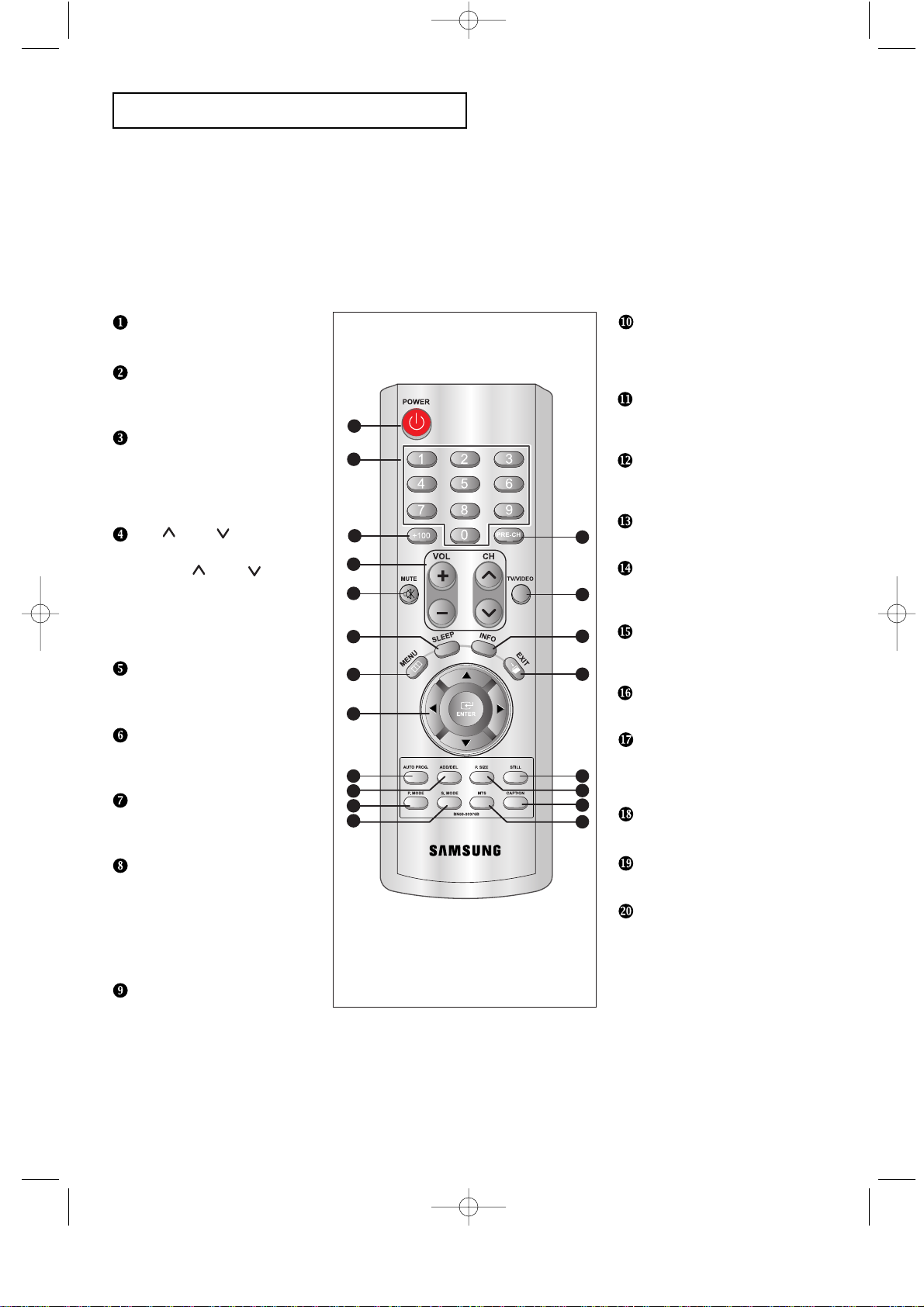
YOUR NEW TV
Remote Control
Frequently Used Buttons
1
2
3
5
4
6
7
8
9
11
12
10
13
14
16
17
18
19
20
15
POWER
(See Page 13)
Turns the TV on and off.
NUMBER BUTTONS
Press to select channels
directly on the TV.
+100
Press to select channels over 100.
For example, to select channel
121, press “+100,” then press
“2” and “1.”
CH and CH
(Channel Up/Down)
Press CH or CH to change
channels.
VOL +, VOL -
Press to increase or decrease
the volume.
MUTE
(See Page 14)
Press to temporarily cut off
the sound.
SLEEP
(See Page 32)
Press to select a time for the TV to
turn off automatically.
MENU
Displays the main on-screen
menu.
JOYSTICK
Use to select on-screen menu
items and change menu values.
(The remote control will only
function with VCR or DVD units
that are compatible with the LCD
TV.)
AUTO PROG.
Use to store the broadcast/cable
channels that you receive.
You can use the remote control up to a distance of about 23 feet from the TV. When using the remote,
always point it directly at the TV.
ADD/DEL
Use to choose channels yourself
and store them or delete them from
memory.
P.MODE
Adjusts the TV picture by selecting
one of the preset factory settings.
S.MODE
Adjust the TV sound by selecting
one of the preset factory settings
PRE-CH
Tunes to the previous channel.
TV/VIDEO
Press to display all of the
available video sources.
Info Display
Use to see information on the
current broadcast.
EXIT
Press the menu to exit.
STILL
Press to stop the action during
a particular scene. Press again to
resume normal video.
P.SIZE
Press to change the screen size.
CAPTION
Press to set caption on/off.
MTS
(Multichannel Television Stereo)
Press to choose stereo, mono or
Separate Audio Program
(SAP broadcast).
01-12 5/30/03 10:40 AM Page 4
English-5
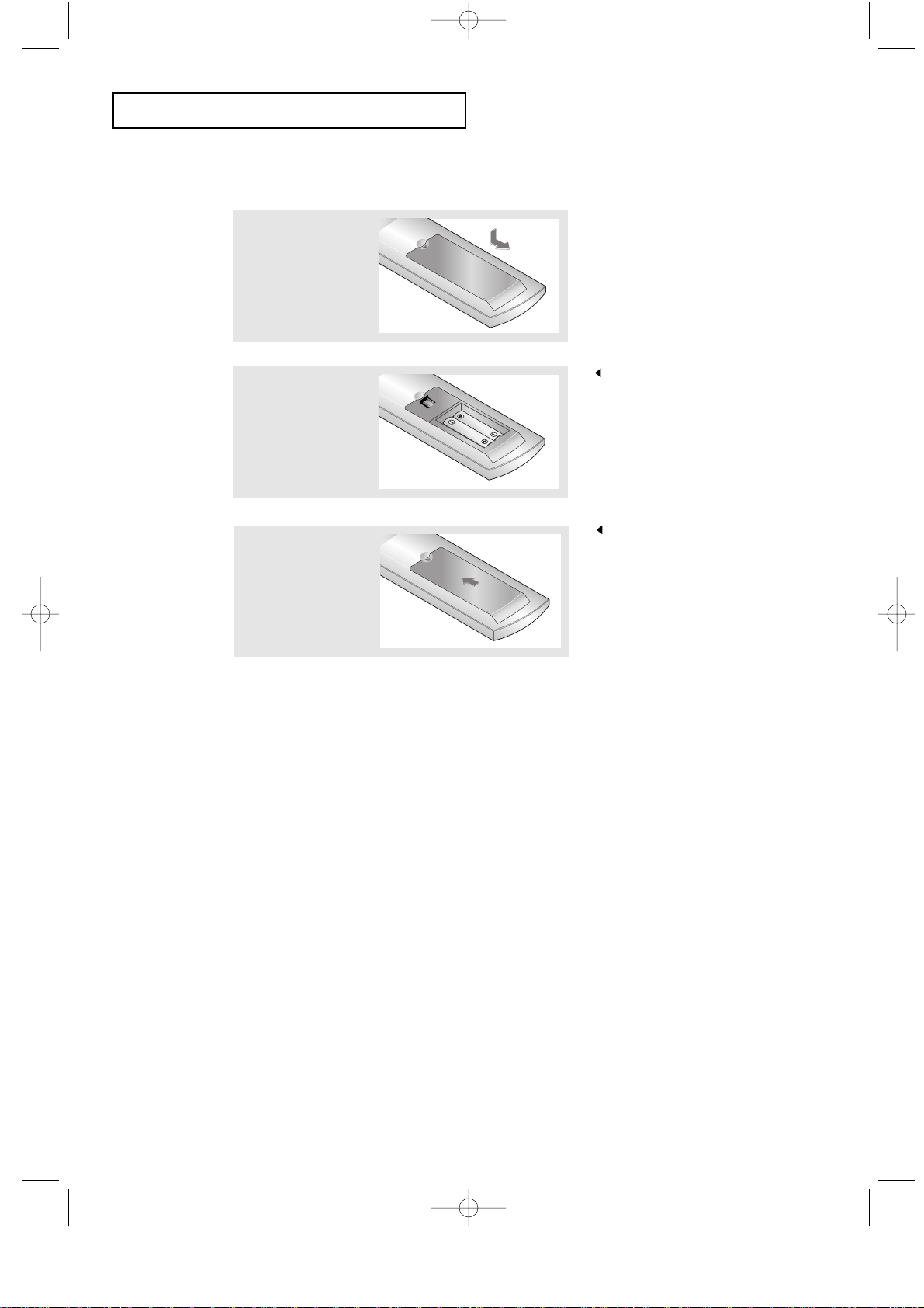
3
Replace the cover.
Remove the batteries and store them
in a cool, dry place if you won’t be
using the remote control for a long
time.
The remote control can be used
up to about 23 feet from the TV.
(Assuming typical TV usage,
the batteries last for about one year.)
2
Install two AAA size
batteries.
Make sure to match the “+” and
“
–” ends of the batteries with the
diagram inside the compartment.
Installing Batteries in the Remote Control
1
Slide the cover out
completely.
YOUR NEW TV
The remote control doesn’t work!
Check the following:
1. Is the TV power switch on?
2. Are the plus end and the minus end of the battery reversed?
3. Did the battery run out?
4. Is the power out, or is the power cord unplugged?
5. Is there a special fluorescent light or a neon sign nearby?
01-12 5/30/03 10:40 AM Page 5
English-6
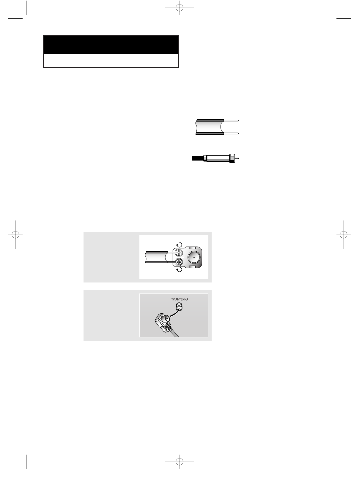
Connecting VHF and UHF Antennas
If your antenna has a set of leads that
look like this, see “Antennas with
300-ohm Flat Twin Leads”, below.
If your antenna has one lead that looks
like this, see “Antennas with 75-ohm
Round Leads”, on page 7.
If you have two antennas, see “Separate
VHF and UHF Antennas”, on page 7.
Antennas with 300-ohm Flat Twin Leads
If you are using an off-air antenna (such as a roof antenna or “rabbit ears”) that has
300-ohm twin flat leads, follow the directions below.
Chapter Two
INSTALLATION
1
Place the wires from
the twin leads under
the screws on a 30075 ohm adaptor (not
supplied). Use a
screwdriver to tighten
the screws.
2
Plug the adaptor into
the TV ANTENNA
terminal on the
bottom of the back
panel.
01-12 5/30/03 10:40 AM Page 6
English-7
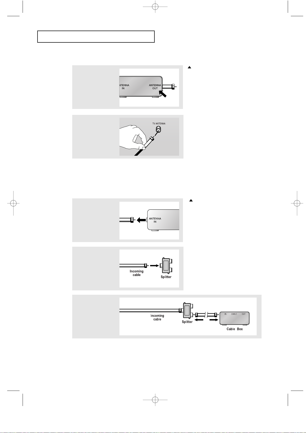
Connecting Cable TV
To connect to a cable TV system, follow the instructions below.
Cable without a Cable Box
1
Plug the incoming
cable into the TV
ANTENNA terminal
on back of the TV.
Because this TV is cable-ready,
you do not need a cable box to
view unscrambled cable channels.
2
Plug the combiner
into the TV
ANTENNA terminal
on the bottom of
the rear panel.
INSTALLATION
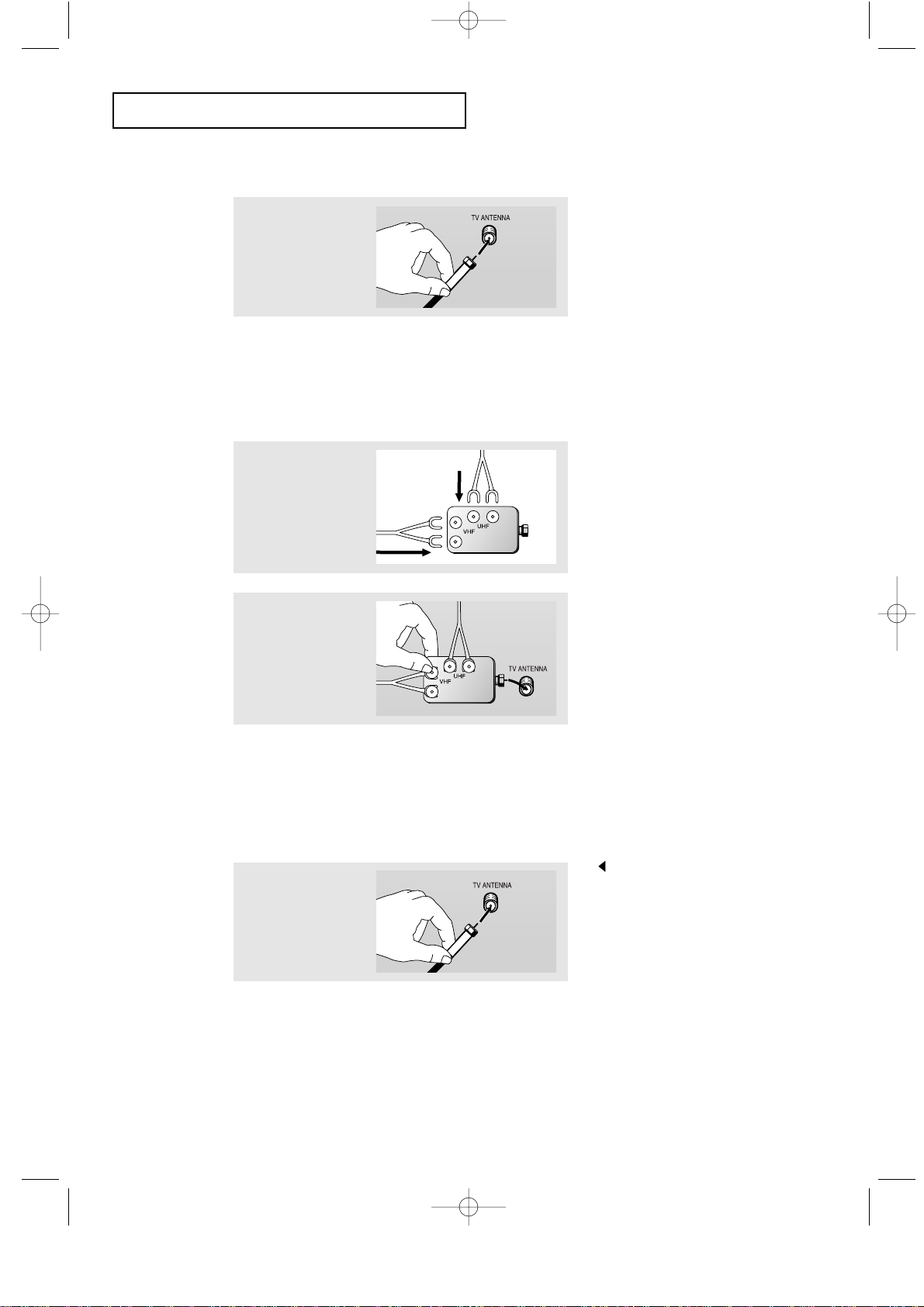
Antennas with 75-ohm Round Leads
1
Plug the antenna
lead into the TV
ANTENNA terminal
on the bottom of the
back panel.
Separate VHF and UHF Antennas
If you have two separate antennas for your TV (one VHF and one UHF), you must
combine the two antenna signals before connecting the antennas to the TV. This
procedure requires a an optional combiner-adaptor (available at most electronics shops).
1
Connect both antenna
leads to the combiner.
01-12 5/30/03 10:40 AM Page 7
English-8
INSTALLATION
Connecting to a Cable Box that Descrambles All Channels
1
Find the cable that is
connected to the
ANTENNA OUT
terminal on your cable
box.
This terminal might be labeled
“ANT OUT”, “VHF OUT”, or
simply, “OUT”.
2
Connect the other end
of this cable to the TV
ANTENNA terminal on
the back of the TV.
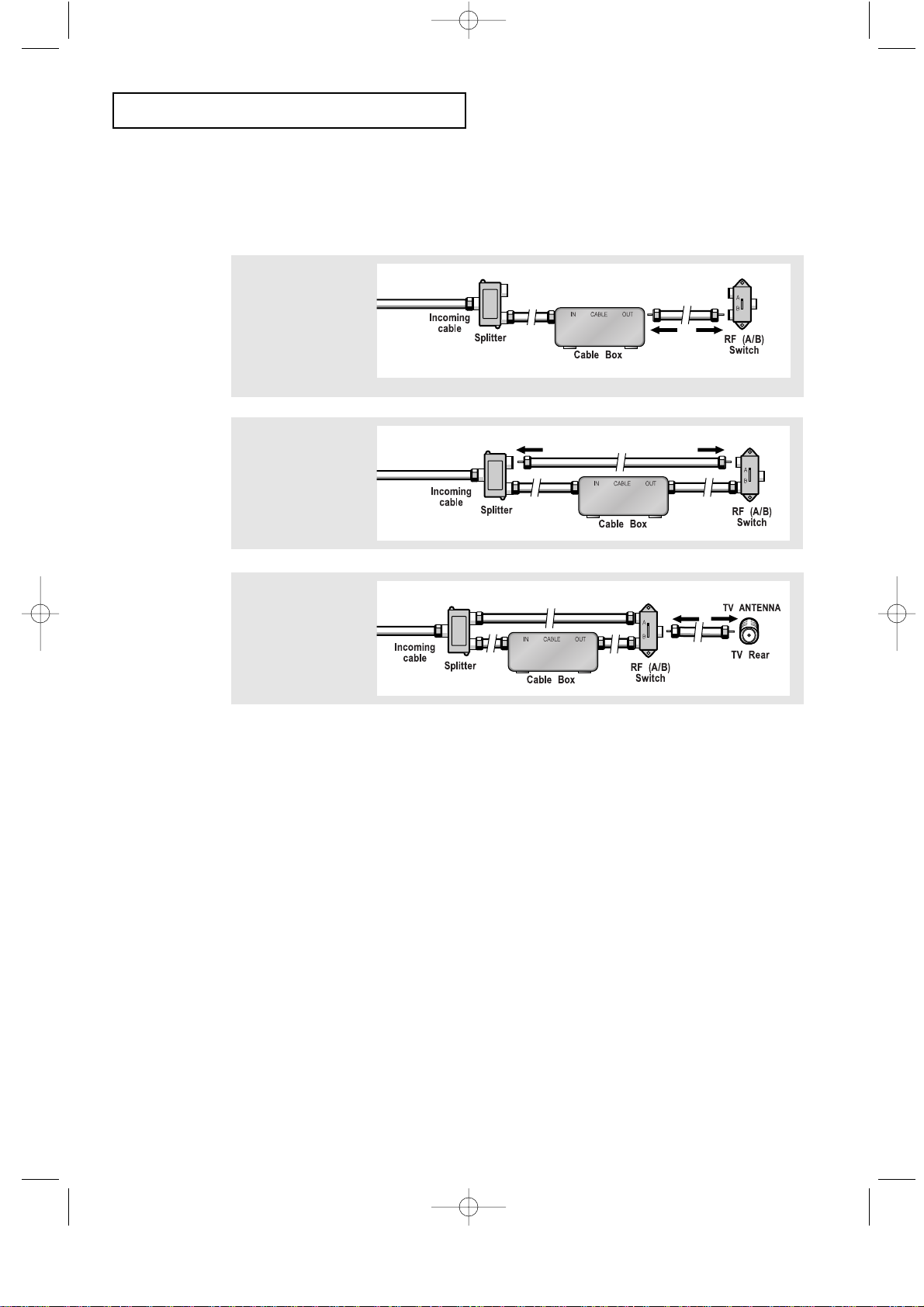
Connecting to a Cable Box that Descrambles Some Channels
If your cable box descrambles only some channels (such as premium channels), follow the
instructions below. You will need a two-way splitter, an RF (A/B) switch, and four lengths
of coaxial cable. (These items are available at most electronics stores.)
1
Find and disconnect
the cable that is
connected to the
ANTENNA IN terminal
on your cable box.
This terminal might be labeled
“ANT IN”, “VHF IN”, or simply,
“IN”.
2
Connect this cable
to a two-way splitter.
3
Connect a coaxial
cable between an
OUTPUT terminal on
the splitter and the IN
terminal on the cable
box.
01-12 5/30/03 10:40 AM Page 8
English-9
4
Connect a coaxial
cable between the
ANTENNA OUT
terminal on the
cable box and the
B–IN terminal on the
A/B switch.
5
Connect another
cable between the
other OUT terminal
on the splitter and
the A–IN terminal on
the RF (A/B) switch.
6
Connect the last
coaxial cable
between the OUT
terminal on the RF
(A/B) switch and the
VHF/UHF terminal
on the rear of the
TV.
INSTALLATION
After you’ve made this connection, set the A/B switch to the “A” position for normal
viewing. Set the A/B switch to the “B” position to view scrambled channels.
(When you set the A/B switch to “B,” you will need to tune your TV to the cable box’s
output channel, which is usually channel 3 or 4.)
01-12 5/30/03 10:40 AM Page 9
 Loading...