

Samsung DVD-R120-AXAX, DVD-R120-AXAP, DVD-R120-ASTR, DVD-R120-ARCL, DVD-R120-AXAO Service Manual
...
DVD-RECORDER
Chassis : K2 (2nd Generation)
DVD-R120/AXAX, AXAP, ASTR, ARCL, AXAO
DVD-R121/AXAX, AXAP, ASTR, ARCL, AXAO
SERVICE
ΠMulti format recording
DVD-RAM/ DVD-RW/ DVD-R
´ Multi format playback
DVD/ DVD-RAM/ DVD-RW/ DVD-R
CD/ CD-R/ CD-RW/ MP3/ JPEG
ˇ Recording mode
XP(1Hour)/ SP(2Hour)/ LP(4Hour)/ EP(6~8Hour)
¨ Progressive scan
ˆ Automatic Chapter product on
Ø 59mm Slim Design
Manual
DVD-RECORDER CONTENTS
SERVICE MANUAL
DVD-R120/R121
© Samsung Electronics Co., Ltd. DEC. 2005
Printed in Korea
AK82-01020A
• The appearance of DVD-R120/XAX and appearance of DVD-R120/AXAX is same.
However it will be able to distinguish with seeing the inside.
DVD-R120/XAX uses LSI LOGIC MAIN ASSY, but DVD-R120/AXAXuses SAMSUNG MAIN ASSY.
• How to identify them by Label-Rating ; See next page.
When servicing, be sure to confirm the model name on Label-Rating of Chassis-Rear.
This Service Manual is a property of Samsung Electronics Co.,Ltd.
Any unauthorized use of Manual can be punished under applicable
international and/or domestic law.
DVD-R120
DVD-R121
ELECTRONICS

CONTENTS
1. Precautions 1-1 ~ 1-6
1-1 Safety Precaution (1-1)
1-2 Servicing Precautions (1-3)
1-3 ESD Precautions (1-4)
1-4 Handling the optical pick-up (1-5)
2. Product Specification 2-1 ~ 2-12
2-1 Reference Information (2-1)
2-2 Chassis Product Specification (2-2)
2-3 Option Product Specification (2-3)
2-4 Introduction to DVD (2-4)
2-5 DVD-Video Fromat (2-6)
3. Software Update 3-1 ~ 3-4
3-1 Drive Firmware Update (3-1)
3-2 Flash Update (3-3)
4. Disassembly and Reassembly 4-1 ~ 4-8
4-1 Cabinet and PCB (4-1)
4-2 PCB Location (4-7)
5. Trouble Shooting 5-1 ~ 5-16
6. Exploded View and Parts List 6-1 ~ 6-6
6-1 Cabinet Assembly (DVD-R120 Only) (6-2)
6-2 Cabinet Assembly (DVD-R121 Only) (6-4)
7. Electrical Parts List 7-1 ~ 7-12
8. Block Diagrams 8-1 ~ 8-8
8-1 All Block Diagram (8-2)
8-2 U1(S5L3200) Block Diagram (8-3)
8-3 AU2(PCM1742) Block Diagram (8-4)
8-4 AU5 (PCM1802) Block Diagram (8-5)
8-5 U11 (TSB4AB1) Block Diagram (8-6)
8-6 VU1(TW9906) Block Diagram (8-7)
8-7 IC4N01(MSP3407G) Block Diagram (8-8)

9. Wiring Diagram 9-1 ~ 9-2
10. PCB Diagrams 10-1 ~ 10-10
10-1 S.M.P.S. PCB (DVD-R120 Only) (10-2)
10-2 S.M.P.S. PCB (DVD-R121 Only) (10-4)
10-3 Main PCB (10-6)
10-4 Jack PCB (10-8)
10-5 Key PCB (DVD-R121 Only) (10-10)
11. Schematic Diagrams 11-1 ~ 11-16
11-1 S.M.P.S. (DVD-R120 Only) (11-2)
11-2 S.M.P.S. (DVD-R121 Only) (11-3)
11-3 DVD Main Connector (11-4)
11-4 DVD DDR (11-5)
11-5 DVD DV (11-6)
11-6 DVD A/V Codec (11-7)
11-7 DVD Audio In/Out (11-8)
11-8 DVD Video Decoder (11-9)
11-9 MICOM (11-10)
11-10 A/V Input (11-11)
11-11 A/V Output (11-12)
11-12 TM Block (11-13)
11-13 Flash Memory (11-14)
11-14 Key (DVD-R121 Only) (11-15)
12. Operating Instructions and Installation 12-1 ~ 12-72
13. Circuit Operating Descriptions 13-1 ~ 13-16
13-1 Power (13-1)
13-2 AV Codec (13-4)
13-3 SERVO (DVP Multi Drive) (13-7)
13-4 Video Input (13-9)
13-5 Video Output (13-11)
13-6 Audio (13-13)
13-7 Tuner (13-14)
13-8 IF (13-15)
CONTENTS

14. Reference Information 14-1 ~ 14-4
CONTENTS
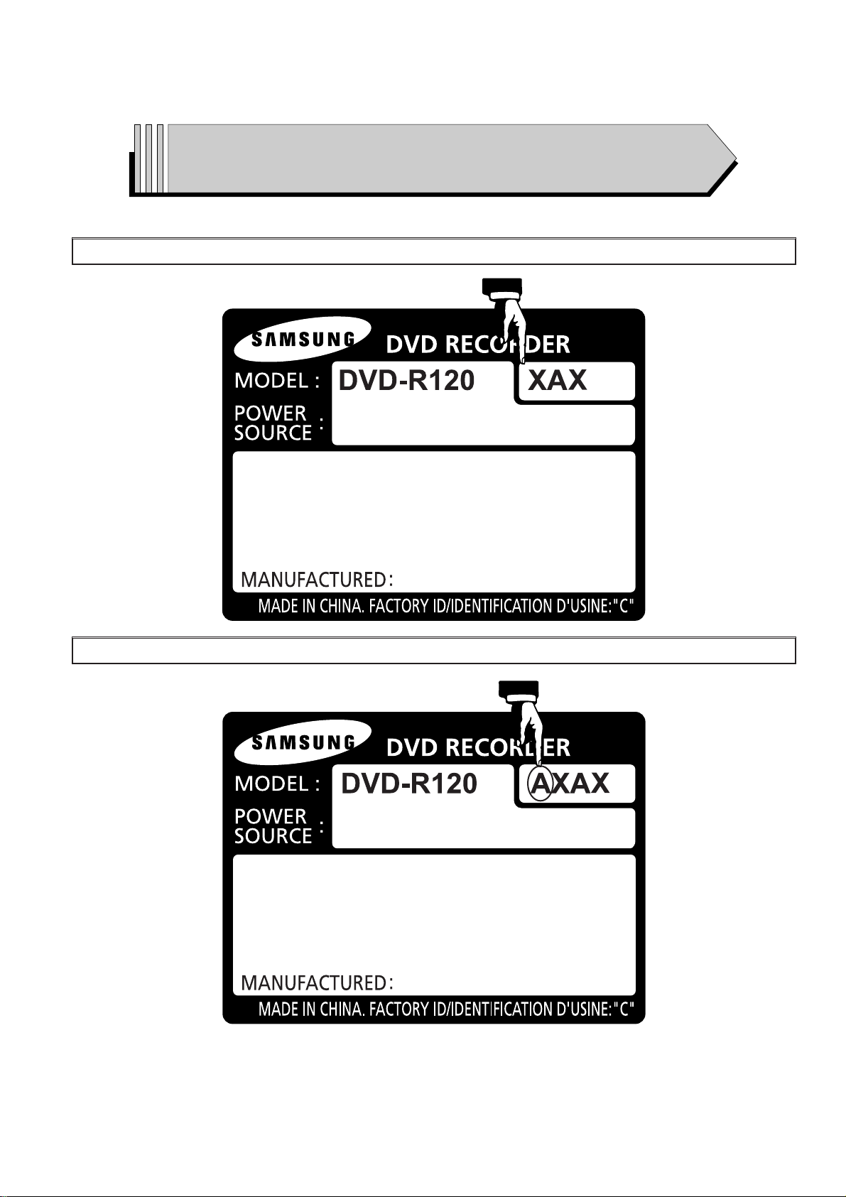
How to identify DVD-R120/AXAX (Uses SAMSUNG MAIN ASSY)
from DVD-R120/XAX (Uses LSI LOGIC MAIN ASSY)
DVD-R120/XAX (Uses LSI LOGIC MAIN ASSY)
DVD-R120/AXAX (Uses SAMSUNG MAIN ASSY)
Samsung Electronics 1-1
1. Precautions
1-1 Safety Precautions
1) Before returning an instrument to the customer,
always make a safety check of the entire instrument,
including, but not limited to, the following items:
(1) Be sure that no built-in protective devices are
defective or have been defeated during servicing.
(1)Protective shields are provided to protect both
the technician and the customer. Correctly replace
all missing protective shields, including any
removed for servicing convenience.
(2)When reinstalling the chassis and/or other assembly in the cabinet, be sure to put back in place
all protective devices, including, but not limited to,
nonmetallic control knobs, insulating fish papers,
adjustment and compartment covers/shields, and
isolation resistor/capacitor networks. Do not operate this instrument or permit it to be operated without all protective devices correctly installed and
functioning.
(2) Be sure that there are no cabinet openings through
which adults or children might be able to insert
their fingers and contact a hazardous voltage. Such
openings include, but are not limited to, excessively wide cabinet ventilation slots, and an improperly fitted and/or incorrectly secured cabinet back
cover.
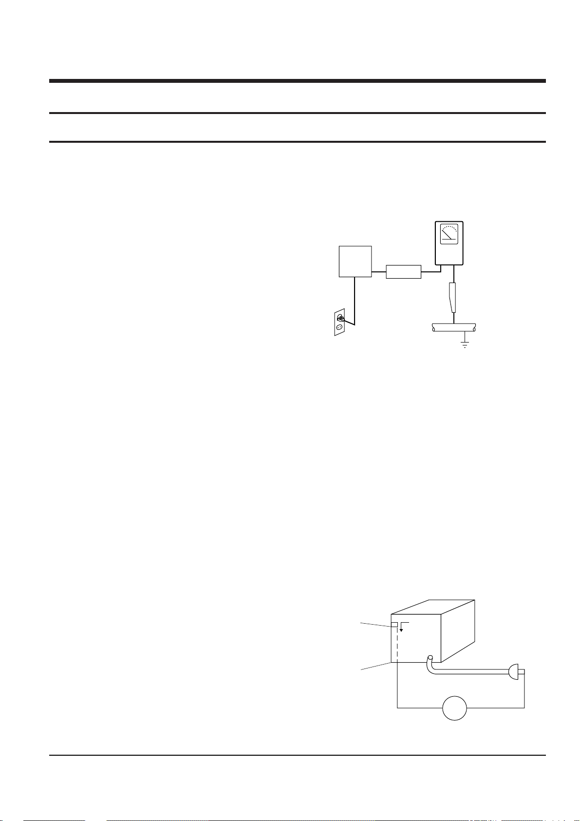
(3) Leakage Current Hot Check-With the instrument
completely reassembled, plug the AC line cord
directly into a 120V AC outlet. (Do not use an isolation transformer during this test.) Use a leakage
current tester or a metering system that complies
with American National Standards institute (ANSI)
C101.1 Leakage Current for Appliances and
Underwriters Laboratories (UL) 1270 (40.7). With
the instrument’s AC switch first in the ON position
and then in the OFF position, measure from a
known earth ground (metal water pipe, conduit,
etc.) to all exposed metal parts of the instrument
(antennas, handle brackets, metal cabinets, screwheads, metallic overlays, control shafts, etc.), especially any exposed metal parts that offer an electrical return path to the chassis.
Any current measured must not exceed 0.5mA.
Reverse the instrument power cord plug in the outlet and repeat the test. See Fig. 1-1.
Any measurements not within the limits specified
herein indicate a potential shock hazard that must
be eliminated before returning the instrument to
the customer.
Fig. 1-1 AC Leakage Test
(4) Insulation Resistance Test Cold Check-(1) Unplug
the power supply cord and connect a jumper wire
between the two prongs of the plug. (2) Turn on the
power switch of the instrument. (3) Measure the
resistance with an ohmmeter between the
jumpered AC plug and all exposed metallic cabinet
parts on the instrument, such as screwheads,
antenna, control shafts, handle brackets, etc. When
an exposed metallic part has a return path to the
chassis, the reading should be between 1 and 5.2
megohm. When there is no return path to the chassis, the reading must be infinite. If the reading is
not within the limits specified, there is the possibility of a shock hazard, and the instrument must be
repaired and rechecked before it is returned to the
customer. See Fig. 1-2.
Fig. 1-2 Insulation Resistance Test
DEVICE
UNDER
TEST
(READING SHOULD
NOT BE ABOVE
0.5mA)
LEAKAGE
CURRENT
TESTER
EARTH
GROUND
TEST ALL
EXPOSED METER
SURFACES
ALSO TEST WITH
PLUG REVERSED
(USING AC ADAPTER
PLUG AS REQUIRED)
2-WIRE CORD
Antenna
Terminal
Exposed
Metal Part
ohm
ohmmeter

Precautions
1-2 Samsung Electronics
2) Read and comply with all caution and safety related notes on or inside the cabinet, or on the chassis.
3) Design Alteration Warning-Do not alter or add to
the mechanical or electrical design of this instrument. Design alterations and additions, including
but not limited to, circuit modifications and the
addition of items such as auxiliary audio output
connections, might alter the safety characteristics of
this instrument and create a hazard to the user. Any
design alterations or additions will make you, the
servicer, responsible for personal injury or property
damage resulting therefrom.
4) Observe original lead dress. Take extra care to
assure correct lead dress in the following areas:
(1) near sharp edges, (2) near thermally hot parts (be
sure that leads and components do not touch thermally hot parts), (3) the AC supply, (4) high voltage,
and (5) antenna wiring. Always inspect in all areas
for pinched, out-of-place, or frayed wiring, Do not
change spacing between a component and the
printed-circuit board. Check the AC power cord for
damage.
5) Components, parts, and/or wiring that appear to
have overheated or that are otherwise damaged
should be replaced with components, parts and/ or
wiring that meet original specifications.
Additionally, determine the cause of overheating
and/or damage and, if necessary, take corrective
action to remove any potential safety hazard.
6) Product Safety Notice-Some electrical and mechanical parts have special safety-related characteristics
which are often not evident from visual inspection,
nor can the protection they give necessarily be
obtained by replacing them with components rated
for higher voltage, wattage, etc. Parts that have special safety characteristics are identified by shading,
an ( )or a ( )on schematics and parts lists. Use
of a substitute replacement that does not have the
same safety characteristics as the recommended
replacement part might create shock, fire and/or
other hazards. Product safety is under review continuously and new instructions are issued whenever appropriate.

Precautions
Samsung Electronics 1-3
1-2 Servicing Precautions
CAUTION : Before servicing units covered by this
service manual and its supplements, read and follow
the Safety Precautions section of this manual.
Note : If unforseen circumstances create conflict
between the following servicing precautions and any
of the safety precautions, always follow the safety precautions. Remember: Safety First.
1-2-1 General Servicing Precautions
(1) a. Always unplug the instrument’s AC power cord
from the AC power source before (1) re-moving
or reinstalling any component, circuit board,
module or any other instrument assembly, (2)
disconnecting any instrument electrical plug or
other electrical connection, (3) connecting a test
substitute in parallel with an electrolytic capacitor in the instrument.
b. Do not defeat any plug/socket B+ voltage inter-
locks with which instruments covered by this
service manual might be equipped.
c. Do not apply AC power to this instrument and
/or any of its electrical assemblies unless all
solid-state device heat sinks are correctly installed.
d. Always connect a test instrument’s ground lead
to the instrument chassis ground before connecting the test instrument positive lead. Always
remove the test instrument ground lead last.
Note : Refer to the Safety Precautions section ground
lead last.
(2) The service precautions are indicated or printed on
the cabinet, chassis or components. When servicing, follow the printed or indicated service precautions and service materials.
(3) The components used in the unit have a specified
flame resistance and dielectric strength.
When replacing components, use components
which have the same ratings. Components identified by shading, by( ) or by ( ) in the circuit diagram are important for safety or for the characteristics of the unit. Always replace them with the exact
replacement components.
(4) An insulation tube or tape is sometimes used and
some components are raised above the printed
wiring board for safety. The internal wiring is
sometimes clamped to prevent contact with heating components. Install such elements as they
were.
(5) After servicing, always check that the removed
screws, components, and wiring have been installed correctly and that the portion around the
serviced part has not been damaged and so on.
Further, check the insulation between the blades of
the attachment plug and accessible conductive
parts.
1-2-2 Insulation Checking Procedure
Disconnect the attachment plug from the AC outlet
and turn the power ON. Connect the insulation resistance meter (500V) to the blades of the attachment
plug. The insulation resistance between each blade of
the attachment plug and accessible conductive
parts(see note) should be more than 1 Megohm.
Note : Accessible conductive parts include metal panels, input terminals, earphone jacks, etc.

Precautions
1-4 Samsung Electronics
1-3 ESD Precautions
Electrostatically Sensitive Devices (ESD)
Some semiconductor (solid state) devices can be damaged easily by static electricity.
Such components commonly are called Electrostatically Sensitive Devices(ESD). Examples of typical ESD
devices are integrated circuits and some field-effect
transistors and semiconductor chip components. The
following techniques should be used to help reduce
the incidence of component damage caused by static
electricity.
(1) Immediately before handling any semiconductor
component or semiconductor-equipped assembly,
drain off any electrostatic charge on your body by
touching a known earth ground. Alternatively,
obtain and wear a commercially available discharging wrist strap device, which should be
removed for potential shock reasons prior to applying power to the unit under test.
(2) After removing an electrical assembly equipped
with ESD devices, place the assembly on a conductive surface such as aluminum foil, to prevent electrostatic charge buildup or exposure of the assembly.
(3) Use only a grounded-tip soldering iron to solder or
unsolder ESD devices.
(4) Use only an anti-static solder removal devices.
Some solder removal devices not classified as
“anti-static” can generate electrical charges sufficient to damage ESD devices.
(5) Do not use freon-propelled chemicals. These can
generate electrical charges sufficient to damage
ESD devices.
(6) Do not remove a replacement ESD device from its
protective package until immediately before your
are ready to install it.(Most replacement ESD
devices are packaged with leads electrically shorted together by conductive foam, aluminum foil or
comparable conductive materials).
(7) Immediately before removing the protective ma-
terials from the leads of a replacement ESD device,
touch the protective material to the chassis or circuit assembly into which the device will be
installed.
CAUTION : Be sure no power is applied to the chassis or circuit, and observe all other safety precautions.
(8) Minimize bodily motions when handling unpack-
aged replacement ESD devices. (Otherwise harmless motion such as the brushing together of your
clothes fabric or the lifting of your foot from a carpeted floor can generate static electricity sufficient
to damage an ESD device).

Precautions
Samsung Electronics 1-5
1-4 Handling the optical pick-up
The laser diode in the optical pick up may suffer electrostatic breakdown because of potential static electricity from clothing and your body.
The following method is recommended.
(1) Place a conductive sheet on the work bench (The
black sheet used for wrapping repair parts.)
(2) Place the set on the conductive sheet so that the
chassis is grounded to the sheet.
(3) Place your hands on the conductive sheet(This
gives them the same ground as the sheet.)
(4) Remove the optical pick up block
(5) Perform work on top of the conductive sheet. Be
careful not to let your clothes or any other static
sources to touch the unit.
◆ Be sure to put on a wrist strap grounded to the
sheet.
◆ Be sure to lay a conductive sheet made of copper
etc. Which is grounded to the table.
Fig.1-3
(6) Short the short terminal on the PCB, which is in-
side the Pick-Up ASS’Y, before replacing the PickUp. (The short terminal is shorted when the PickUp Ass’y is being lifted or moved.)
(7) After replacing the Pick-up, open the short termi-
nal on the PCB.
THE UNIT
WRIST-STRAP
FOR GROUNDING
1M
1M
CONDUCTIVE SHEET

Precautions
1-6 Samsung Electronics
MEMO
Product Specification
Samsung Electronics 2-1
Power requirements 127V ca ~ 60Hz
Power consumption 35Watts
General
Weight 8.27 IB
Dimensions 16.9in(W) x 9.6in(D) x 2.3in(H)
Operating temp +41°F to 95°F
Other conditions Keep level when operating. Less than 75% operating humidity
Video (1,2)
1.0 V p-p at 75ohm load, sync negative
S-Video input (Y:1.0Vp-p, C: 0.286Vp-p at 75ohm load)
Audio (1,2) Max. Audio input level : 2Vrms
Input DV Input IEEE 1394(4p) compatible jack
Receivable Channels
Regular TV broadcasting : VHF (2~13), UHF (14~69)
Cable TV broadcasting: 1~125
Audio output jacks 1,2
Optical/coaxial digital audio output
Audio
Full scale analog output level : 2Vrms
Output
Video output jacks 1,
S-Video output 1 (Y: 1.0Vp-p, C:0.286Vp-p at 75 ohm load)
Video
Component output (Y: 1.0Vp-p ,Pb:0.70Vp-p, Pr:0.70Vp-p at 75ohm load)
Picture compression format MPEG-II
Audio compression format Dolby digital 2ch/256kbps
Recording
Recording Quality
XP (about 8 Mbps), SP (about 4 Mbps), LP (about 2 Mbps),
EP (about 1.2 Mbps), FR (about 1.2 Mbps to 8Mbps)
Audio frequency characteristics 20 Hz ~ 20 KHz
2. Product Specification
2-1 Product Specification
Product Specification
2-2 Samsung Electronics
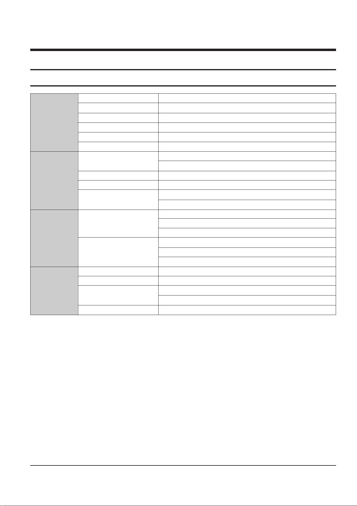
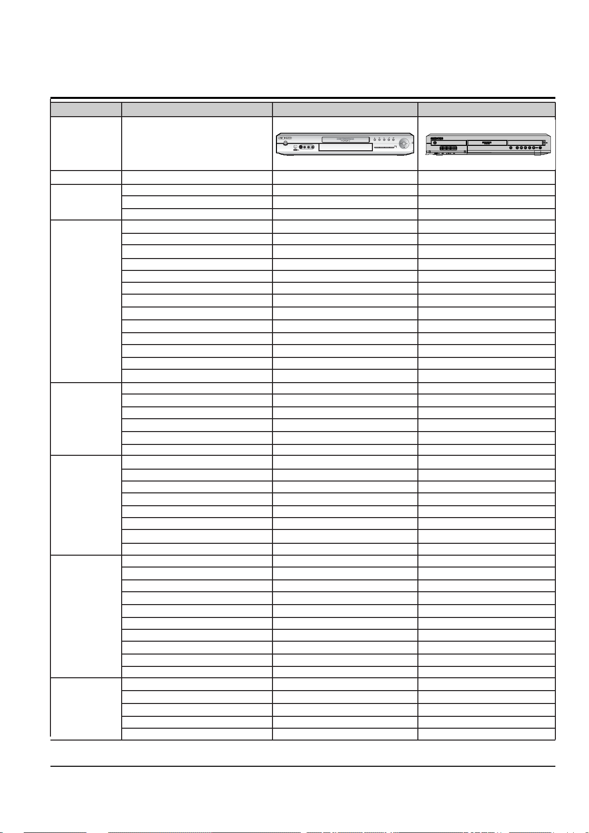
2-2 Chassis Product Specification
General Model Name DVD-R100 DVD-R120
Info Function Standard Standard
COLOR SYSTEM NTSC NTSC
SYSTEM BROADCAST SSTEM M M
AUTO CLOCK O O
DVD-RAM O O
DVD-R O O
DVD-RW O O
VIDEO MPEG-2 MPEG-2
AUDIO 2ch 2ch
RECORER DVD-RAM/-R(4.7GB) O O
FUNCTION HDD - -
Flexible Recording O O
OTR O O
Time Slip O O
VCR+Plus -/- -/-
Quick Dubbing - -
EPG(Gemstar) - -
IR Blaster - -
Play Lis O O
SUB Auto Chaptering - FUNCTION JPEG Browser with BG music - O
DV Input O O
10in2 Memory Slot - -
DVD-RAM/-R/-RW O/O/(O) O/O/(O)
DVD-Video/VCD/CD-DA O/O/O O/O/O
CD-R/RW O/O O/O
PLAYBACK Music CD O O
FUNCTION MPEG4/Divx -/- -/-
Multi Memory Card - -
Progressive Scan Output O O
Upscaling(720P/1080i) - -
DV/LINE1/LINE2/CH O/O/O/O O/O/O/O
Video Input 2ea 2ea
Video Output 1ea 1ea
S-Video Input 2ea 1ea
S-Video Outpu 1ea 1ea
IN/OUT Component Output 1ea 1ea
HDMI Output - -
Analog Audio Input(L/R) 2sets 2sets
Analog Audio Output(L/R) 2sets 2sets
Optical/Coaxial O/O O/O
Panel disply VFD LED Module
REMOCON Multi 53key Multi 44key
ETS IB Spanish Spanish
Size: Net(W x H x D) 430X68.5X279 430X59X245
Weight 4.2Kg 2.9Kg
DV INDV IN
S-VIDEOS-VIDEO VIDEOVIDEO
LASTLAST MARK MARK PIPPIP INPUTINPUT TIME SLIPTIME SLIP
MODEMODE
RECREC
CHCH CHCH
L(MONO)-AUDIO-RL(MONO)-AUDIO-R
DVD RECORDER DVD-R100
L2 INL2 IN
Product Specification
Samsung Electronics 2-3
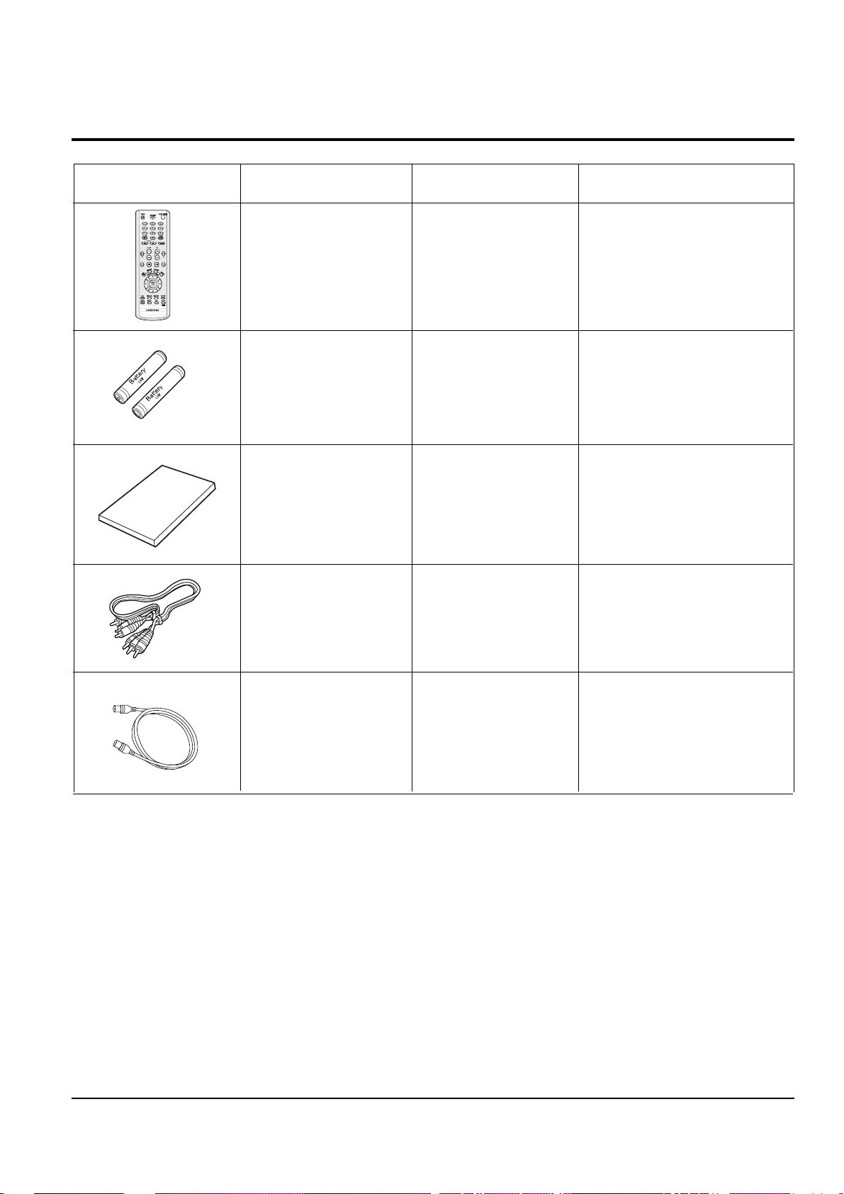
2-3 Option Product Specification
Description Fig Description
Remote
Control
Batteries for
Remote Control
RF Cable
Video/Audio
Cable
Parts No
AK59-00012H
AC43-12002H
AK68-00686A
AC39-00073A
AC39-42001J
Remark
Qwner's Instructions
Model Standard of
DVD-R120/AXAX
Model Standard of
DVD-R120/AXAX
Model Standard of
DVD-R120/AXAX
Model Standard of
DVD-R120/AXAX
Model Standard of
DVD-R120/AXAX

Product Specification
2-4 Samsung Electronics
2-4 Introduction to DVD
2-4-1 The Definition of DVD
DVD is the next generation medium and is the acronym of the Digital Versatile Disc or thr Digital Video Disc,
which maximizes the saving density of the disk surface using the MPEG-2 compression technology to enable the
storage of 17G bytes of data on the same size CD.
1) 7 times the storage capacity of the conventional CD
•Minimized the track pitch and pit size to 1/2 of conventional CD.
•Uses red laser with short-wavelenght of 650nm (635nm).
• DVD Vs. CD-ROM
CD-ROM CD-R/RW DVD-ROM DVD-R/RW DVD-RAM
Disc Thickness 1.2mm 1.2mm 0.6*2mm 0.6*2mm 0.6*2mm
Lens NA 0.45 0.45(0.5) 0.6 0.6 0.6
Laser wavelenght 780um 780um 650um 650um 650um
Track pitch 1.6pm 1.6pm 0.74pm 0.74pm 0.615pm
Capacity 0.65GB 0.65GB 4.7GB 4.7GB 4.7GB
Track structure Pit train Groove Pit train Groove Land/Groove
2) Disc Formats
DVD consists of two 0.6mm discs attached together, enabling access to the upper and lower side of the disk,
and 4 sides could be used at maximum.
Single Layer : 4.7GByte
Polycarbonate
Label
Bonding layer
Reflective layer
Polycarbonate
Label
Polycarbonate
Bonding layer
Reflective layer
Semi-reflective layer
Polycarbonate
Dual Layer : 8.5GByte
Bonding layer
Reflective layer
Reflective layer
Polycarbonate
Polycarbonate
Dual Side Single Layer : 9.5GByte
Polycarbonate
Bonding layer
Reflective layer
Reflective layer
Semi-reflective layer
Semi-reflective layer
Polycarbonate
Dual Side Dual Layer : 17GByte

Product Specification
Samsung Electronics 2-5
2-4-2 DVD Types
FORMAT TYPE APPLICATIONS
DVD-Video Playback Only High quality image and sound for movies and other video media.
DVD-ROM Read Only Multi-functional, multi-midia software that requires large storage capacity.
DVD-Audio Playback Only High quality sound that exceeds the CD, multi-channel Audio.
DVD-R 1 Time Recording As with CD-R, write only once
DVD-RAM
Rewritable This can be virtually used as hard-disk, with a random
(more than 100,000times) read-write access
Rewritable Similar to DVD-RAM except than its technology features
DVD-RW
(About 1000times) a separated read-write access more like phonograph than a hard disk.

Product Specification
2-6 Samsung Electronics
2-5 DVD-Video Fromat
2-5-1 Main Features
1) Able to store up to 160 minutes of Movie by utilizing the MPEG-2 compression technology. ( Aver. 133min.)
2) Enables more than 500 lines of horizontal resolution. (Class corresponding to the Master Tapes used in
broadcasting stations)
3) Provides Dolby Digital 5.1ch Surround 3D sound, which enables theater quality sound (NTSC area).
• For PALareas, 1 of either MPEG-2 Audio or Dolby Digital must be selected.
4) Multi-Language
• Able to store up to 8 languages of dubbing.
• Able to store up to 32 subtitle languages.
5) Multi-Aspect Ratio
3TV Mode alternatives ; 16:9 Wide Screen (DVD Basic)/4:3 Pan & Scan/Letter Box.
6) Multi-Story
Possible to implement Interactive Viewing which enables the user to select the scenario.
7) Multi-Angle
Able to view the camera angle you selected among the scenes recorded with multiple camera angles.
Note ; The above media features must have the DVD Title that contains the appropriate contents to function
properly.
2-5-2 Audio & Video Specifications
Classification DVD-Video Video-CD LD
Compression MPEG-2 MPEG-1
Analog
Pixel 720 x 480 352 x 240
VIDEO
Horizontal resolution Max. 500 Lines Max. 250 Lines Max.420 Lines
Compression rate 1/40 1/140
Analog
Transmission speed Max. 9.8Mbps (variable) 1.15Mbps (fixed)
TV aspect 16:9 / 4:3 4:3 4:3
Audio Max. 8 streams 2CH stereo
Recording type Dolby Digital Linear PCM MPEG-1 Layer 2
AUDIO Transmission rate 448Kbps/stream 6.144Mbps/stream 224Kbps
or
Channel 5.1CH/stream 8CH/stream 2CH
Sampling frequency 48KHz 16, 20, 24Bit/48, 96KHz 16Bit/44.1KHz
2 Analog CH.
2 Digital CH.
(16Bit/44.1KHz)
1 Analog CH.
1 Stream of Dolby Digital
2 Digital CH.
(16Bit/44.1KHz)

Product Specification
Samsung Electronics 2-7
2-5-3 Detailed Feature
As the storage capacity increases, the DVD-Video separates the main data and the additional data such as the
Multi-Function into different data areas, enabling the control of time-data ratio to provide the format that enables
the flexible Software development
• 1 Movie (3.5Mbps)
+ Subtitle (1 Language)
+ Surround Audio (1 Language)
= 160min storage (4.673Gbytes)
• 1 Movie (3.5Mbps)
+ Subtitle (4 Language)
+ Surround Audio (4 Language)
= 160min storage (4.680Gbytes)
• 1 Music Video (4Mbps)
+ 2ch High quality Audio (96kHz/24bit)
= 72min storage (4.648Gbytes)
DVD-Video Feature 1 When Developing the DVD Software, various addition and modification is possible.
DVD-Video uses the variable compresion technology, the MPEG-2 to compress the moving image optimally, minimizing the Data loss to Provide a clear, natural screen while increasing the storage time.
DVD-Video Feature 2 Application of the MPEG-2 compression technology.
• MPEG-2 (Variable compression : Max. 1/40)
• Field unit compression.
DVD-Video
• Compression rate change according to the amount of Data.
•Differentiates the still image anf the moving image
compression rete, reducing Data loss and enables
efficient compression.
• MPEG-1 (Fixed compression : Max. 1/140)
• Frame unit compression.
Video-CD
• Compresses all data using the same ratio.
- Fast movements are jagged, and unnatural
Amount of data
Amount of data
Time
Loss area
Time
Product Specification
2-8 Samsung Electronics
DVD-Video can store the audio using the 5.1ch Dolby Digital compression or the advanced Liner PCM method,
providing the better-than-CD quality and theater like audio quality.
• DTS (Digital Theater System)
Home theatre and music playback in the home, DTS provides high quality 5.1-channel surround sound with
many extras not offered by other consumer formats. As well as handling DTS-branded releases from a growing
number of music labels and consumer software producers, DTS provides enhanced 6.1 matrix and DTS 6.1
discrete decoding that envelopes the listener in sound. DTS technology is featured in a wide cross section of
receiver/pre-amplifiers, DVD players and and add-on components from leading consumer audio vendors
• Dolby Digital (AC-3)
- Unlike the traditional Dolby pro-Logic method, the Dolby Digital method separates all 5 main channels
(Front L/R, Center, Surround (Rear) L/R)and the Sub woofer to provide live surround audio.
- Using the Down Mix method, the conventional Dolby Pro-Logic and Stereo are all compatible.
- Each separated channels are played back at CD quality sound. (Frequency band: 20Hz ~ 20KHz)
• Linear PCM (Pulse Code Modulation)
-Provides the high quality Digital sound without the audio data compression.
- Various Digital Recordings are possible as shown in the table to the right.
DVD-Video Feature 3 High quality surround audio.
Sampling Frequency Bit Rate
16bit
48KHz 20bit
24bit
16bit
96KHz 20bit
24bit
• Dolby Digital compatible Audio Mode
Audio Coding
Channel Format
Mode
Front Surround (Rear) Remark
LCRLR
1/0 O Mono
2/0 OO Stereo
3/0 OOO
2/1 OOMono
3/1 OOO Mono Surround
2/2 OOOO
3/2 OOOOO
Product Specification
Samsung Electronics 2-9
• Audio Dubbing - Max. 8 Languages
• Subtitle - Max. 32 Languages. Capable of storing, and selectiong.
• Linear PCM (Pulse Code Modulation)
DVD-Video Feature 4 Multi-Language
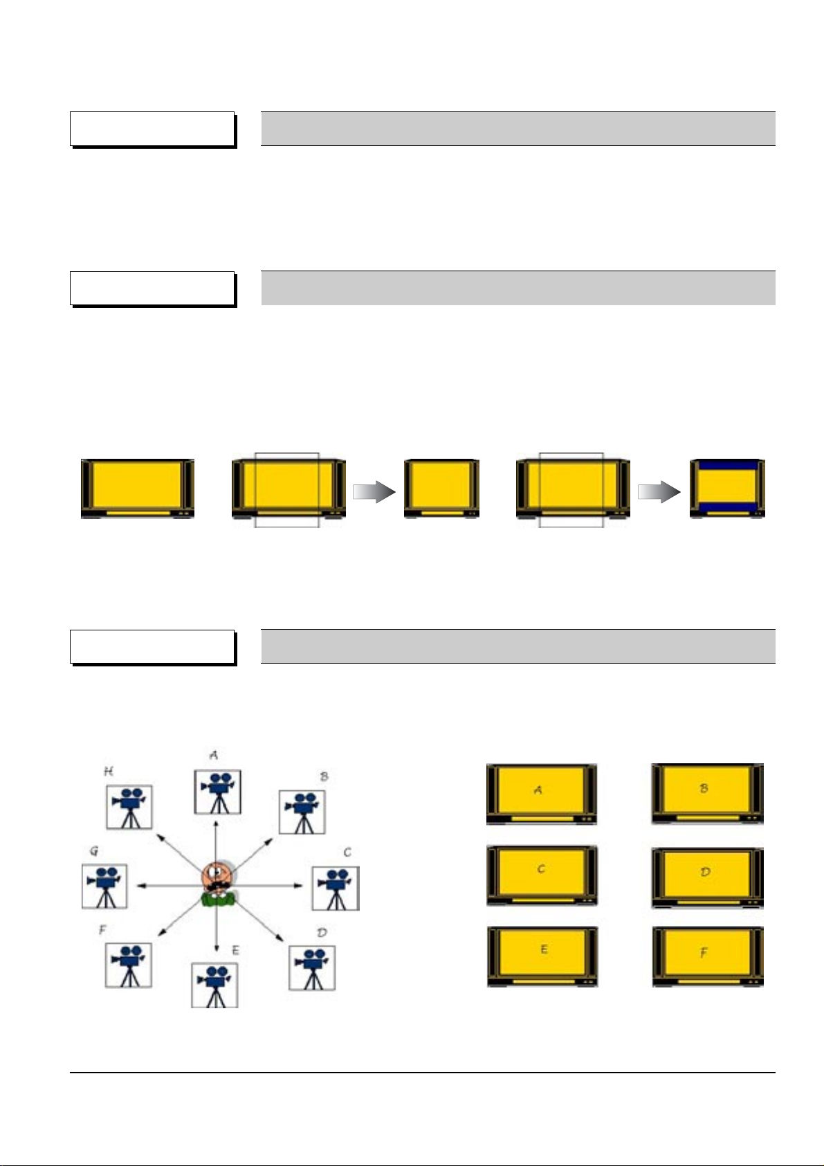
• Unlike the conventional VCD or LD, DVD-Video has the default of 16:9 Wide, and can be viewed using the
conventional 4:3 TV, enabling the expansion of viewer selection capabilities.
• 16 : 9 TV : Wide Mode (16:9 Wide Full Screen)
• 4 : 3 TV : Letter Box Mode, Pan & Scan Mode
DVD-Video Feature 5 Multi-Aspect
4:3 Pan & Scan
16:9 Wide
4:3 Letter Box
• Up to 9 angles of view may be stored, enabling the viewer to select a specific viewpoint at a given time.
--> Especially, for the Music Video and Sports Title, this provides a more lively image of the scene.
DVD-Video Feature 6 Multi-Angle
Note ; Only enable to be worked correctly by an appropriate data supported this function in Disc.
Note ; Only enable to be worked correctly by an appropriate data supported this function in Disc.
Product Specification
2-10 Samsung Electronics
• DVD-Video provides the enviroment suitable for the bi-directional Software develoment, providing multiple
scenarios. This feature enables the Multi-Story function.
DVD-Video Feature 7
Multi-Story
• For the titles that are not suitable for children viewing, Parental Locks are set, requesting user defined
passwords for viewing
• Parential Locks may be set on specific frames of the Title, enabling the player to skip those frames during
playback.
OPTION Parental Lock
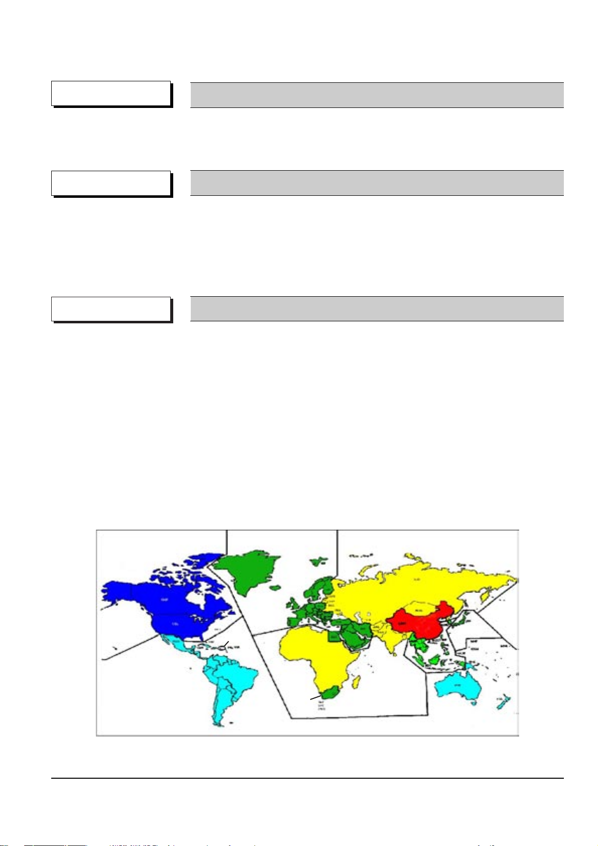
• Classify the world into 6 regions, and if the DVD Title and the Player’s “Reginal Code” do not agree, playback
is prohibited.
• Regionnal Coding is optional for the Soft developers (Region 0 All Code), but the Hardware developers
must adopt the appropriate regionnal code for sale.
• Region 1 : The United States and its territories, Canada.
• Region 2 : Europe, Japan, Greenland, Egypt, South Africa, the Middle East.
• Region 3 : Taiwan, Hongkong, Korea, South East Asia.
• Region 4 : Mexico, South America, Australia, New Zealand.
• Region 5 : Russia, Eastern Europe, India, Africa.
• Region 6 : China. • Region 0 : Worldwide (All Code)
COPYRIGHT Regional Code & Macrovision
• Adoptation of the Macrovision System disables the copying on to other media.
Œ
Œ
¨
¨
Œ
´
ˇ
ˆ
Ø
´
´
ˆ

Product Specification
Samsung Electronics 2-11
• The image quality of the DVD-Video may vary accoring to the quality of the Master and the Authoring Process
• The image quality of the DVD-Video varies according to the Digital Mastering Source such as the
conventional LD, VCD, or Original Film.
• Different Authoring Process are used accoring to the Software developers, and this may affect the
DVD image quality.
• Authoring Process
Remark DVD-Video Authoring Process
Video/Audio
Master
Surround Audio
Master
Subtitle
Master
MPEG-2
Encoding
AC-3/MPEG Audio
Encoding
Cutting
Master
Disc
Production
Subtitle
Encoding
Authoring Process
Video/Audio
Subtitle
Multiplexing
bit stream
bit stream
bit stream

Product Specification
2-12 Samsung Electronics
MEMO

Samsung Electronics
3-1
3. Software Update
3-1 Drive Firmware Update
3-1-1 Introduction
When you can not record and play on specific recording media (especially on newly available DVD-RAM, DVD-RW or DVD-R).
3-1-2 How to make an update disc
• Write the downloaded file onto a blank CD-R or CD-RW disc, using the following settings :
1) Download the software update file from the samsung internet site. (www.samsung.com)
2) Write the file to disc using the CD-RW of your computer.
• Recommended Application Program
- Nero Burning / Easy CD Creator ..etc
• Option
- Name : SDM2224
- Extension name : “*.REC”
- Multisession : No Multisession
- File name lenght : Max. of 11 = 8 + 3
- Format : Mode 1
- Character set : ISO 9660 or Joliet Format
- CD Close & Dise at once
N O T E
It is very important : please read the below notice below before upditang your unit.
The followong events may interrupt the update process and MAY RESULT IN PERMANENT DAMAGE TO THE UNIT WHILE UPDATING
! Unplugging the power cord.
@ Power Outage.
# Dirt or Scratches on the disc.
$ Opening a disc tray during processing.
WARNING
3-2
Software Update
Samsung Electronics
Fig. 3-1
* If you don’t see the message above, try another disc. Generally, this is caused by disc quality and by disc creating problem.
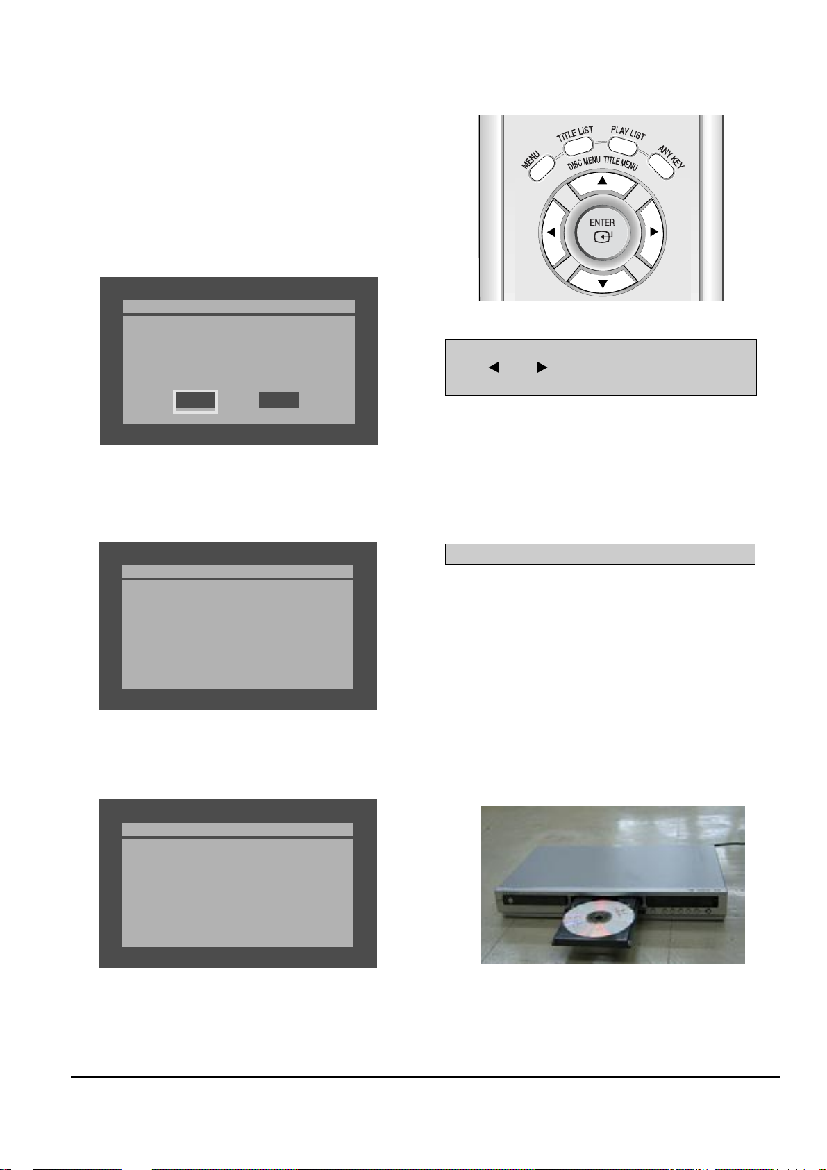
4) Press the ENTER button on the remote control (Fig. 3-2).
Fig.3-3
5) It takes about 1~2 minutes to complete the update.
The message below will be displayed in the screen after update is completed and the tray will open automatically.
Fig. 3-4
6) After removing the update disc, turn off the unit with power button.
And there after turn on the unit with power button and then the will be closed.
The drive firmware is now completed.
Drive Update
Do you want to update drive-firmware?
Version: Xx.X.R120 -> XX.X.R120
No
Yes
Atfer checking old and new version, select “Yes” or “No”
with “” or “ ” on the remote control.
* The Version is indicated by “XX.X modelname”
You will see “LOAD” on FLT Display.
Drive Update
Now, processing...
please, do not turn off the power.
Drive Update
Drive firmware is successfully
updated.
Fig. 3-5
1) Press OPEN/CLOSE to open the disc tray.
2) Insert the update CD-R disc with the software update, label
facing up.
3) Press OPEN/CLOSE to close the disc tray.
* It takes about 1~2 minites before the mesage below appears.
Fig. 3-2 Remote Control

Software Update
3-3
Samsung Electronics
3-2 Flash Update
3-2-1 Introduction
When you encounter the problem which is not related in drive firmware necessity.
3-2-2 How to make an update disc
Write the downloaded file onto a blank CD-R or CD-RW disc, using the following settings :
1) Download the software update file from the samsung internet site. (www.samsung.com)
2) Write the file to disc using the CD-RW of your computer.
• Recommended Application Program
- Nero Burning / Easy CD Creator ..etc
• Option
- Multisession : No Multisession
- CD close & disc at once
- ISO 9660 or joliet format
- Extension name : “*.RUF”
• In order to increase dise playability, add a dummy file (over 100MB) together with the latest program.
(The dummy file can be used any kind of file except MP3 file etc which can be played in the unit and we recommend to use a file whin
extension name as “*.dmy”, which can be changed from original one.)
N O T E
It is very important : please read the below notice below before updating your unit.
The followong events may interrupt the update process and MAY RESULT IN PERMANENT DAMAGE TO THE UNIT WHILE UPDATING
! Unplugging the power cord.
@ Power Outage.
# Dirt or Scratches on the disc.
$ Opening a disc tray during processing.
WARNING
3-4
Software Update
Samsung Electronics
Fig. 3-6
* If you don’t see the message above, try another disc.
Generally, this is caused by disc quality and by disc creating problem.
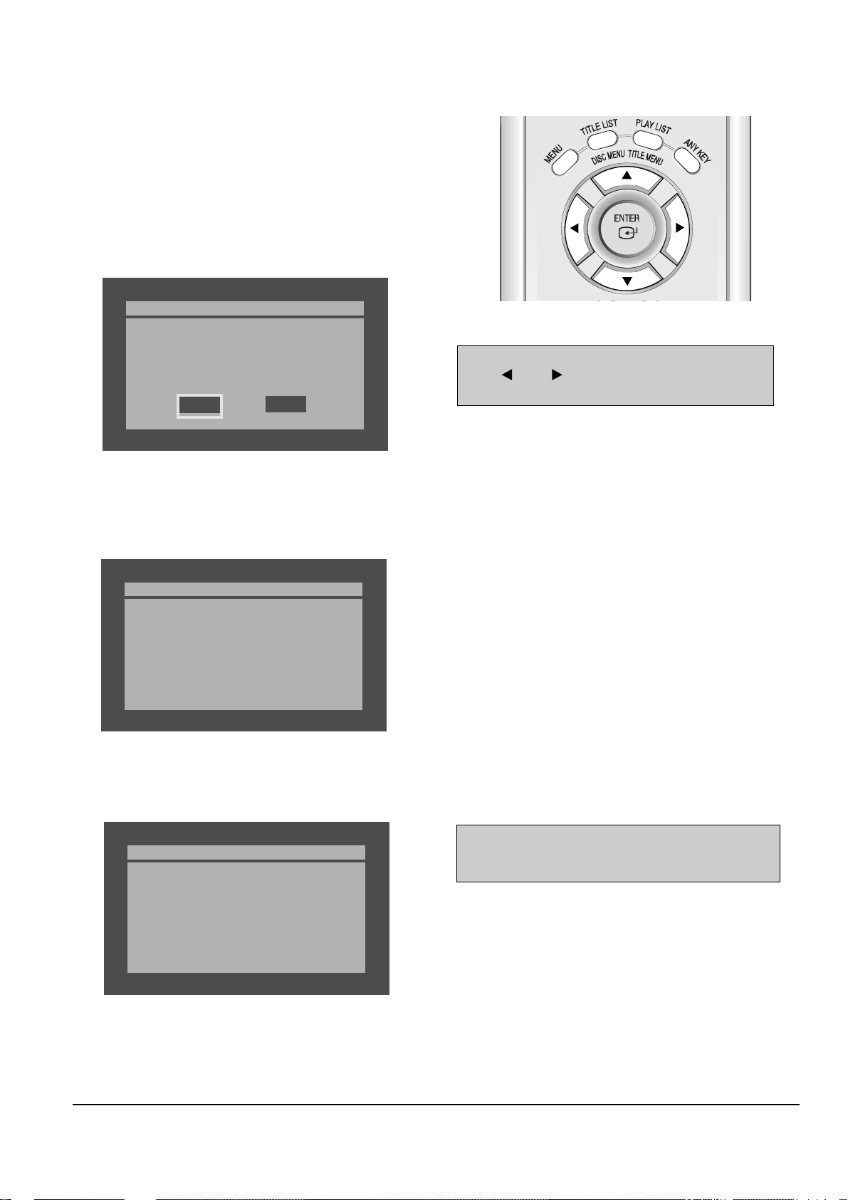
4) Press the ENTER button on the remote control (Fig. 3-7).
Fig. 3-8
5) It takes about 5 minutes to complete the update.
The message below will be displayed in the screen after update is completed and the tray will open automatically.
Fig. 3-9
6) After removing the update disc, turn off the unit with power button.
And there after turn on the unit with power button and then the will be closed.
The Flash update is now completed.
* If the message to the left isn’t displayed after 10minutes
and the unit is no longer functioning properly, contact a
samsung authorized service center.
Atfer checking old and new version, select “Yes” or “No”
with “” or “ ” on the remote control.
* The Version is indicated by “YYMMDD.xx modelname”
Flash Update
Do you want to update flash memory?
Version : YYMMDD.xx.R120
-> YYMMDD.xx.R120
No
Yes
Flash Update
Now, Processing...
Plase. do not turn off the power.
Flash Update
Flash memory is successfully
updated.
1) Press OPEN/CLOSE to open the disc tray.
2) Insert the update CD-R disc with the software update, label
facing up.
3) Press OPEN/CLOSE to close the disc tray.
Fig. 3-7 Remote Control

Samsung Electronics
4-1
4. Disassembly and Reassembly
4-1 Cabinet and PCB
4-1-1 Top Cabinet Removal
1) Remove 3 Screws Œ.
2) Lift up the Top Cabinet in direction of arrow.
Π3 SCREWS
(W 3 x 10)
Fig. 4-1 Top Cabinet Removal
Note : Reassembly in reverse order.

4-2
Samsung Electronics
Disassembly and Reaasembly
ˇ 2 HOOKS
ˆ ASS'Y FRONT-CABINET
´ 1 HOOK
Π1 HOOK
¨ 2 HOOKS
Fig. 4-2 Ass’y Front-Cabinet Removal
4-1-2 Ass’y Front-Cabinet Removal
1) Release 6 Hooks Œ, ´, ˇ, ¨ and Ass’y Front-Cabinet ˆ.
 Loading...