

Samsung DSB-3800 User Manual
DSR 3800, DSR 3700
DSR 3800, DSR 3700
Instructions foruse
DIGITAL SATELLITE RECEIVERDIGITAL SATELLITE RECEIVER
DSR 3800, DSR 3700
DSR 3800, DSR 3700
Warning! Important Safety Instructions
Thank You for Choosing Samsung
Thank you for choosing Samsung! Your new Samsung Digital satellite receiver represents
the latest in IRD technology. We designed it with easy-to-use on-screen menus and closed
captioning capabilities, making it one of the best products in its class. We are proud to offer
you a product that will provide convenient, dependable service and enjoyment for years to come.
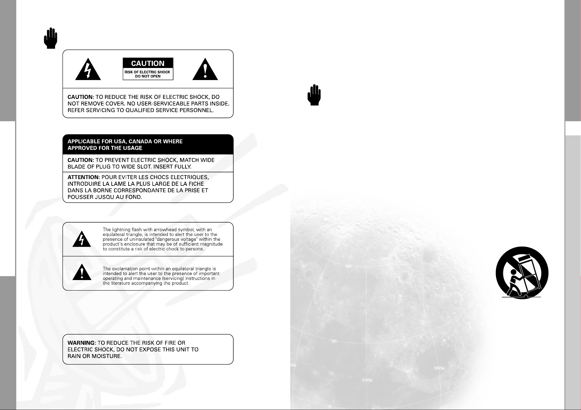
Warning! Important Safety Instructions
Always be careful when using your product. To reduce the risk of fire, electrical shock,
and other injuries, keep these safety precautions in mind when installing, using, and
maintaining your machine.
• Read all safety and operating instructions before operating your product.
• Keep the safety and operating instructions for future reference.
• Heed all warnings on the product receiver and in the operating instructions.
• Follow all operating and use instructions.
• Unplug the product from the wall outlet before cleaning. Use a damp cloth; do not use liquid
or aerosol cleaners.
• Never add any attachments and/or equipment without approval of the manufacturer.
Such additions can increase the risk of fire, electric shock, or other personal injury.
• Do not use the product where contact with or immersion in water is a possibility,
such as near bath tubs, sinks, washing machines, swimming pools, etc.
• Do not place the product on an unstable cart, stand, tripod, bracket,
or table where it can fall. A falling product can cause serious injury to
a child or adult, and serious damage to the appliance.
Use only with a cart, stand, tripod, bracket, or table recommended
by the manufacturer or sold with the product.
Follow the manufacturer’s instructions when mounting the unit,
and use a mounting accessory recommended by the manufacturer.
Move the product and cart with care. Quick stops, excessive force,
and uneven surfaces can make the unit and cart unsteady and likely
to overturn.
• Provide ventilation for the product. The unit is designed with slots in the cabinet for ventilation to
protect it from overheating. Do not block these openings with any object, and do not place the
product on a bed, sofa, rug, or other similar surface. Do not place it near a radiator or heat
register. If you place the product on a rack or bookcase, ensure that there is adequate ventilation
and that you’ve followed the manufacturer’s instructions for mounting.
• Operate your product only from the type of power source indicated on the marking label.
If you are not sure of the type of power supplied to your home, consult your appliance dealer
or local power company.
DIGITAL SATELLITE RECEIVER
1
DSR 3800, DSR 3700
Warning! Important Safety Instructions
DSR 3800, DSR 3700
• Use only a grounded or polarized outlet. For your safety, this product is equipped with a polarized
alternating current line plug having one blade wider than the other. This plug will fit into the power
outlet only one way. If you are unable to insert the plug fully into the outlet, try reversing the plug.
If the plug still does not fit, contact your electrician to replace your outlet.
• Protect the power cord. Power supply cords should be routed so that they won’t be walked on
or pinched by objects placed on or against them. Pay particular attention to cords at plugs,
convenience receptacles, and the point where they exit from the unit.
• Unplug the product from the wall outlet and disconnect the antenna or cable system during a
lightning storm or when left unattended and unused for long periods of time.
This will prevent damage to the unit due to lightning and power-line surges.
• Avoid overhead power lines. An outside antenna system should not be placed in the vicinity of
overhead power lines or other electric light or power circuits or where it can fall into such power
lines or circuits. When installing an outside antenna system, be extremely careful to keep from
touching the power lines or circuits. Contact with such lines can be fatal.
• Do not overload the wall outlet or extension cords. Overloading can result in fire or electric shock.
• Do not insert anything through the openings in the unit, where they can touch dangerous voltage
points or damage parts. Never spill liquid of any kind on the product.
• Do not attempt to service the product yourself. Refer all servicing to qualified service personnel.
Unplug the unit from the wall outlet and refer servicing to qualified service personnel under the
following conditions:
- when the power-supply cord or plug is damaged
- if liquid has been spilled on the unit or if objects have fallen into the unit
- if the product has been exposed to rain or water
- if the product does not operate normally by following the operating instructions
- if the product has been dropped or the cabinet has been damaged
- when the product exhibits a distinct change in performance
• If you make adjustments yourself, adjust only those controls that are covered by the operating
instructions. Adjusting other controls may result in damage and will often require extensive work
by a qualified technician to restore the product to normal.
• When replacement parts are required, be sure the service technician uses replacement parts
specified by the manufacturer or those that have the same characteristics as the original part.
Unauthorized substitutions may result in additional damage to the unit.
• Upon completion of any service or repairs to this product, ask the service technician to
perform safety checks to determine that the product is in a safe operating condition.
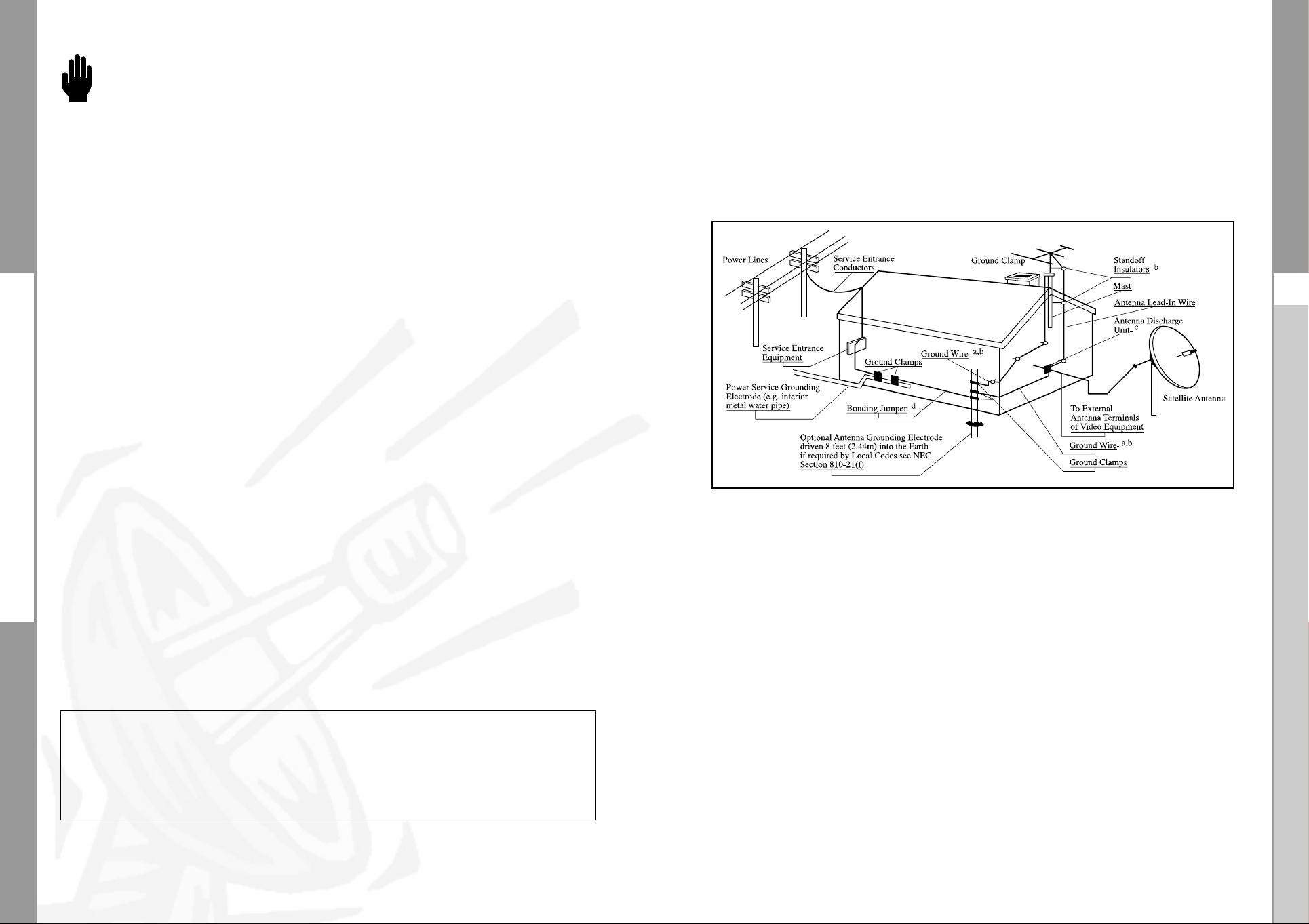
Outdoor Antenna Grounding
Be sure the antenna is properly grounded to provide some protection against voltage
surges and built-up static charges.
Example of Antenna Grounding as per National Electrical Code
Note to CATV System Installer
This reminder is provided to call the CATV system installer’s attention to Article 820-40 of
the NEC that provides guidelines for proper grounding and, in particular, specifies that the
cable ground shall be
connected to the grounding system of the building, as close to the point of cable entry as
practical.
Note: NEC 810-21 ( i )
A bonding jumper not smaller than No. 6 AWG copper or equivalent shall be connected
between radio and television equipment grounding electrode and the
power grounding electrode system at the building or structure served where separate
electrodes are used.
This device complies with part 15 of the FCC Rules.
Operation is subject to the following Two Conditions;
(1) This device may not cuase harmfulinterference, and
(2) This device must accept any interference received, including interference that
may cause undesired operation.
2
DIGITAL SATELLITE RECEIVER
3
DSR 3800, DSR 3700
DSR 3800, DSR 3700
CONTENT GENERAL FEATURES
Warning! Important Safety Instructions . . . . . . . . . . . . . . . . . . . . . 1
General Features. . . . . . . . . . . . . . . . . . . . . . . . . . . . . . . . . . . . . . . 5
Connecting Your DSR 3800, DSR 3700. . . . . . . . . . . . . . . . . . . . . . 6
Description . . . . . . . . . . . . . . . . . . . . . . . . . . . . . . . . . . . . . . . . . . . 8
Front Panel. . . . . . . . . . . . . . . . . . . . . . . . . . . . . . . . . . . . . . . . . . . 8
Rear Panel . . . . . . . . . . . . . . . . . . . . . . . . . . . . . . . . . . . . . . . . . . . 9
Remote Control Unit . . . . . . . . . . . . . . . . . . . . . . . . . . . . . . . . . . . . 10
Basic Functions. . . . . . . . . . . . . . . . . . . . . . . . . . . . . . . . . . . . . . . . 12
Operating The Receiver . . . . . . . . . . . . . . . . . . . . . . . . . . . . . . . . . 17
Main Menu. . . . . . . . . . . . . . . . . . . . . . . . . . . . . . . . . . . . . . . . . . . . 17
1. Installation . . . . . . . . . . . . . . . . . . . . . . . . . . . . . . . . . . . . . . . . 17
1.1 LNB Setting. . . . . . . . . . . . . . . . . . . . . . . . . . . . . . . . . . . . 18
1.2 Positioner Setting. . . . . . . . . . . . . . . . . . . . . . . . . . . . . . . . 18
1.2.1 User Mode . . . . . . . . . . . . . . . . . . . . . . . . . . . . . . . . . . . 19
1.2.2 Installer Mode. . . . . . . . . . . . . . . . . . . . . . . . . . . . . . . . . 20
1.3 Solarsat Setting . . . . . . . . . . . . . . . . . . . . . . . . . . . . . . . . . 20
1.4 Auto Scanning. . . . . . . . . . . . . . . . . . . . . . . . . . . . . . . . . . 21
1.5 Manual Scanning . . . . . . . . . . . . . . . . . . . . . . . . . . . . . . . . 21
1.6 SMATV Scanning . . . . . . . . . . . . . . . . . . . . . . . . . . . . . . . . 22
1.7 Reset to Factory Defaults. . . . . . . . . . . . . . . . . . . . . . . . . . 22
2. Channel Organising . . . . . . . . . . . . . . . . . . . . . . . . . . . . . . . . . 23
2.1 Delete Satellite. . . . . . . . . . . . . . . . . . . . . . . . . . . . . . . . . . 23
2.2 Delete Transponder . . . . . . . . . . . . . . . . . . . . . . . . . . . . . . 23
2.3 Delete Channel . . . . . . . . . . . . . . . . . . . . . . . . . . . . . . . . . 24
2.4 Delete All Channel . . . . . . . . . . . . . . . . . . . . . . . . . . . . . . . 24
2.5 Delete Scrambled Channels . . . . . . . . . . . . . . . . . . . . . . . . 24
2.6 Favorite Channel . . . . . . . . . . . . . . . . . . . . . . . . . . . . . . . . 24
2.7 Move & Edit Channel . . . . . . . . . . . . . . . . . . . . . . . . . . . . . 25
3. Parental Lock . . . . . . . . . . . . . . . . . . . . . . . . . . . . . . . . . . . . . . 26
3.1 Set Channel Lock. . . . . . . . . . . . . . . . . . . . . . . . . . . . . . . . 26
3.2 Change PIN Code . . . . . . . . . . . . . . . . . . . . . . . . . . . . . . . 27
4. System Setup . . . . . . . . . . . . . . . . . . . . . . . . . . . . . . . . . . . . . . 28
4.1 Language Selection . . . . . . . . . . . . . . . . . . . . . . . . . . . . . . 28
4.2 OSD Setting. . . . . . . . . . . . . . . . . . . . . . . . . . . . . . . . . . . . 28
4.3 Media Settings. . . . . . . . . . . . . . . . . . . . . . . . . . . . . . . . . . 29
4.4 Time &Timer Setting. . . . . . . . . . . . . . . . . . . . . . . . . . . . . . 29
4.5 System Information . . . . . . . . . . . . . . . . . . . . . . . . . . . . . . 30
4.6 Software Upgrade . . . . . . . . . . . . . . . . . . . . . . . . . . . . . . . 30
5. Common Interface (DSR3800 Only) . . . . . . . . . . . . . . . . . . . . . 31
Troubleshooting. . . . . . . . . . . . . . . . . . . . . . . . . . . . . . . . . . . . . . . . 32
Disposal. . . . . . . . . . . . . . . . . . . . . . . . . . . . . . . . . . . . . . . . . . . . . . 32
Technical Specifications . . . . . . . . . . . . . . . . . . . . . . . . . . . . . . . . . 33
1. USER SECTION
4000 PROGRAMMABLE CHANNELS
SOFTWARE DOWNLOAD VIA SATELLITE & PC
ADVANCED ELECTRONIC PROGRAM GUIDE
DiSEqC 1.2 SUPPORTED
FULL FUNCTION INFRARED REMOTE CONTROL UNIT
7 SEGMENT LED DISPLAY
AUTO AND MANUAL SCAN FACILITY
CHANNEL ORGANIZING(PROGRAMMABLE)
RCA OUTPUT
LOW POWER CONSUMPTION
9 FAVORITE LISTS
AUTO UPDATED EPG
2. TUNER SECTION
950~2150 MHz WIDE BAND TUNER
IF OUTPUT WITH DC PASS LOOP FOR ANALOG RECEIVER
SUPPORTING DiSEqC 1.2 VERSION
13V/18V SWITCHING
22KHz CONTINUOUS TONE CONTROL
3. VIDEO SECTION
DVB-S COMPLIANT
MPEG-2 VIDEO(MP@ML)
2~45 MS/s SYMBOL RATE
COMPATIBLE FOR BOTH SCPC/MCPC
SUPPORTS ASPECT RATIO 4:3(NORMAL) AND
16:9(WIDE SCREEN)
MODULATOR OUTPUT
4. AUDIO SECTION
MPEG 1 AUDIO LAYER I & II
MONO, DUAL, STEREO AND JOINT STEREO AUDIO MODE
32, 44.1 AND 48 KHz SAMPLING FREQUENCIES
VOLUME CONTROL AND MUTE FUNCTION THROUGH
REMOTE CONTROL UNIT
4
DIGITAL SATELLITE RECEIVER
5
DSR 3800, DSR 3700
CONNECTING YOUR "DSR 3800, DSR 3700"
DSR 3800, DSR 3700
CONNECTING YOUR "DSR 3800,DSR 3700"
1. LOCATION OF THE RECEIVER
Your
DSR 3800, DSR 3700
Don’t put in completely enclosed cabinet that will restrict the flow of air,
resulting in overheating.
The location should be safeguarded from direct sunlight,
excess moisture, rough handling or household pets.
Avoid stacking other electronic components on the top of the receiver.
The location should be safely accessible by the cable from your
antenna system.
should be placed under proper ventilation.
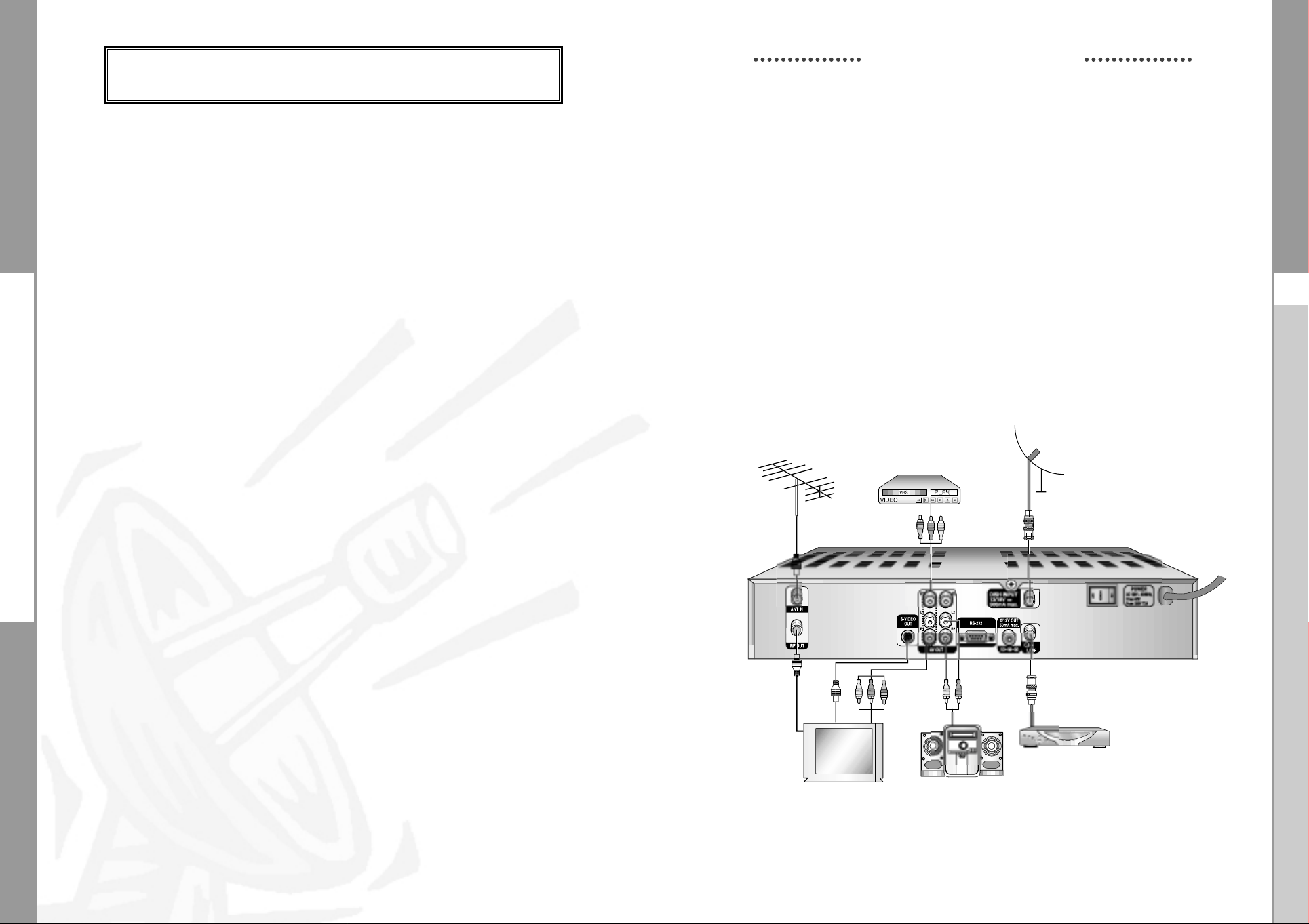
2. CONNECTING THE RECEIVER WITH DISH SYSTEM
After installing your antenna system, connect the coaxial cable from the LNB of
your antenna to "LNB" terminal marked at the rear of the
All cable connectors should be finger tightened; do not use any kind
of wrench while tightenning connectors. The cable should be 75ohm
impedance coaxial twisted at the end with an "F" type connector.
3. CONNECTING THE RECEIVER TO TV
To connect the receiver with your television, you can use three methods;
RF cable, or RCA cable.
Connect the RF cable to the terminal marked "
DSR 3800, DSR 3700
of
In the case of connecting your TV through RCA cable, connect the RCA
connector marked TV to the respective RCA port on the TV.
and its other end to the TV RF input socket.
AV OUT
" at the rear panel
4. CONNECTING YOUR ANALOG RECEIVER
To facilitate the user using analog receiver to view analog channels,
DSR 3800, DSR 3700
as "
LOOP
".
Connect the coaxial cable from this terminal to the IF input terminal of
your analog receiver. Now by keeping the
you will be able to tune and view analog channels from your analog receiver.
has been provided with a loop through terminal marked
DSR 3800, DSR 3700
5. CONNECTING YOUR VCR
To connect a VCR, the DSR 3800
at the rear marked "AV OUT".
Using a RCA connector, the VCR can be connected to the receiver.
, DSR 3700
has been provided with RCA
6. CONNECTING EXTERNAL AUDIO / HI-FI SYSTEM
To connect any exter nal Audio Hi-Fi system, the receiver has been provided
with two RCA connectors at the back of the receiver, marked with AUDIO L and R
respectively to connect the left and right Audio.
DSR 3800, DSR 3700
in standby,
8. INSERTING COMMON INTERFACE CAM AND SMARTCARD
The DSR 3800 supports Common Interface CAMs under DVB specification.
The CI CAMs include a built-in smart card reader.
● Insert the smart card into the CAM gently with the gold colored chip upwards
● Slide in the CAM gently inside the slot so that it sits in the socket tightly.
● Close the door.
● To remove the CAM push the button provided by the side of the CAM slot.
The CAM will be ejected from the socket.
NNoottee :
.
Connecting Figure
The following Common Interface CAMs are available now:
IRDETO, CONAX, CRYPTOWORKS, VIACCESS, NAGRAVISION, SECA, Etc.
6
DIGITAL SATELLITE RECEIVER
7
DSR 3800, DSR 3700
DSR 3800, DSR 3700
DESCRIPTION
DESCRIPTION
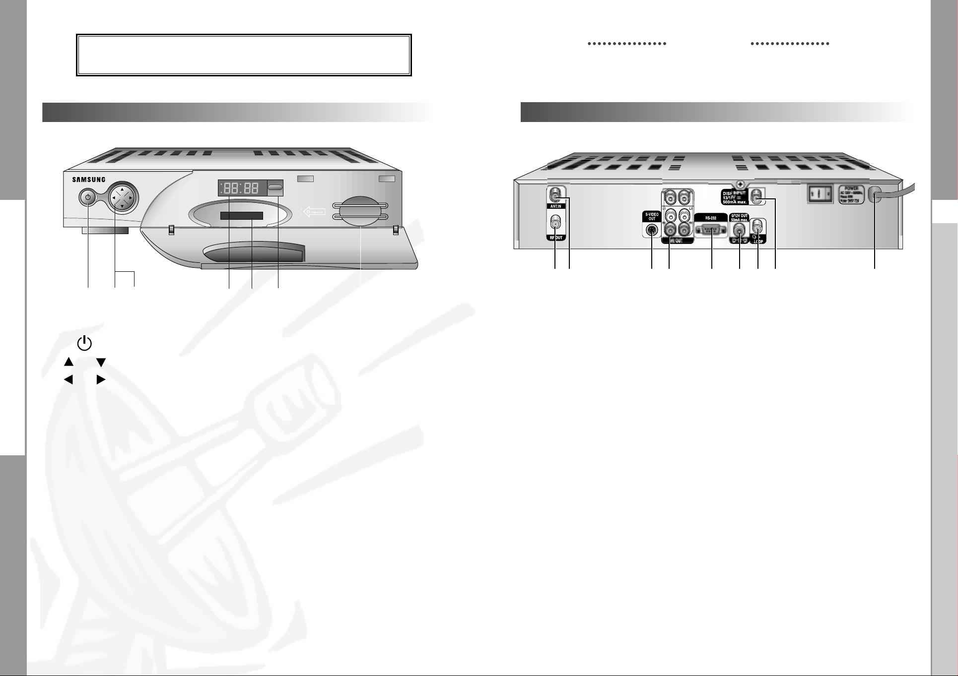
Front Panel
23 645 7
1
1.
2. ,
3. ,
4. 7
Segment Display This LED display will show the current channel number.
5. CAM Slot
This key is used to turn the receiver on and off (Standby).
These keys are used to change the channels.
These keys are used to increase and decrease the volume level
manually.
While the receiver is in Standby mode, the display will
show the current time.
Slot for Common Interface.(DSR 3800 only)
Rear Panel
8765
9
1. AC MAINS This is to plug in the AC mains power cord.
The input AC voltage range is 120V, 60Hz supply.
2. DISH INPUT This port is to connect the coaxial cable from LNB of your dish.
The IF input is provided through this port and the input frequency
range is 950-2150 MHz. Also the voltage switching 13V and
18V is passed through this port.
3. LOOP To enable the connection of an Analog receiver,
The receiver is provided with this ‘
4. 0/12V OUT This is used to connect to an external LNB switch.
4
32
LOOP
’ port.
1
6. Infrar
7. Not Used
ed Sensor This is to receive the IR commands from the Remote
Control Unit.
5. RS 232 DATA PORT This is used to connect your receiver to a computer for reading
and loading data information. (only for service)
6. AV OUT These RCA connectors are used to connect any external
video and audio.
7. S-VIDEO OUT This is used to connect STB to your TV by using S-VHS cable.
8. ANT.IN This is used to connect your local RF channels to
your TV through Loop.
9. RF OUT This is used to connect to your TV via RF cable.
(Preset to channel 3)
8
DIGITAL SATELLITE RECEIVER
9
 Loading...