

Page 1
CONTROL MASTER SERIAL PC INTERFACE + SOFTWARE (PCI)
n
/
n
n
/
n
–
i
CONTROL MASTER INTERFAZ SERIALE DE LA PC + SOFTWARE (PCI)
CONTROL MASTER INTERFACE PÉRIODIQUES DE PC + LOGICIEL (PCI)
Parts and Technical Service guide
Guía de servicio técnico y recambio
Guide d’instructions et pièces de rechange
Ref.:
380310
380310K
Descriptio
Descripción/ Descriptio
E
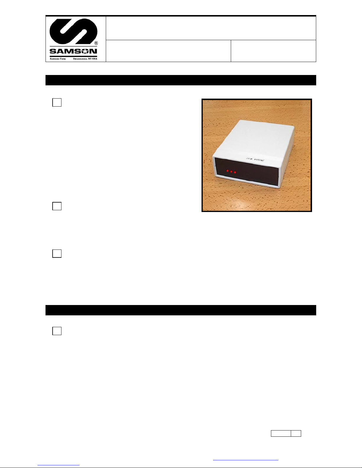
The PC Interface connects to the PC via a standard DB9 serial
cable (provided) and to the Control Master system via the
CANBUS Network cable (by Installer). It provides a two-way link
between the PC and the System, allowing the Control Master
System to send information to the PC and likewise allowing the
PC to communicate with the Control Master System. It is
powered with a small transformer (provided).
NOTE: A dedicated PC is not required. The system will only
interface with ONE PC.
NOTE: The PC interface is also known as the ‘Conductor’ or the
‘Modem’ or the ‘PCI’. These terms are interchangeable.
S
El interfaz de la PC conecta con la PC vía un cable serial DB9 (proporcionado) y con el sistema del amo del
control vía el cable de la red de CANBUS (por Installer). Proporciona un acoplamiento de dos vías entre la PC
y el sistema, permitiendo el sistema envíe la información a la PC y además permitiendo que la PC se
comunique con el sistema. Se acciona con un transformador pequeño (proporcionado).
F
L'interface de PC se relie au PC par l'intermédiaire d'un câble DB9 périodique (fourni) et au système de maître
de commande par l'intermédiaire du câble de réseau de CANBUS (par Installer). Elle fournit un lien bidirectionnel entre le PC et le système, permettant au système d'envoyer l'information au PC et de même
permettant au PC de communiquer avec le système. Elle est actionnée avec un petit transformateur (fourni).
Installation - Operatio
Instalación –Modo de empleo/Installatio
E
• Locate the PCI next to the PC.
• Consult with the on-site PC administrator before touching the PC. Different facilities will have
varying security polices applied to the PC and you may not be able to load the software without their help.
• Typically the PCI will be at the end of the CANBUS Network. If this is true, then open the case (two small
recessed phillips-head screws on the bottom side) and move the small blue Jumper from the factory
default ‘out’ position to the ‘in’ position - pull the Jumper straight up and then reinstall it in the other
position. If the PCI is to be located in any of the middle positions on the CANBUS Network, then do not
open the case and do not move the Jumper from the Factory Default. Visual confirmation of the Jumper
position is impossible, as the circuit board is not legibly marked. You
Jumper using a Multi-Meter before proceeding any further. Probe the CAN H and CAN L terminals on the
back of the unit with the CANBUS disconnected and the power to the unit OFF – Jumper ‘in’ equals 120Ω
(120 OHMS), when the Jumper is ‘out’ there should not be any continuity. See Fig 2.
must
Mode d’emplo
confirm the position of the
Samson Corporation-Swannanoa, NC 28778 800-311-1047 www.samsoncorporation.com
380310
1
Page 2

• Connect the CANBUS cable(s). See Fig 3.
• Connect the provided DB9 Serial Cable to the PC Interface. At the PC plug it into an available serial port.
Sometimes the Serial Port on the PC is not marked
, sometimes it is marked with the symbol l 0 l 0 l and
sometimes there will be a label ‘Comm 1’ or ‘Comm 2’. If the available serial port on the PC is the older
25 pin type, purchase an adapter (DB9 to DB25) from an electronics retailer. For PC’s equipped only with
USB ports an adapter can be purchased in the computer aftermarket and used, but this may require the
assistance of a knowledgeable PC professional (depending on adapter model) and is not factory
supported. See Fig 3.
• Connect the provided Power Supply. See Fig 3.
• To load the provided PC Software, follow the instructions included with the CD. Generally, depending on
the version of Windows: Close all open programs on the PC. Insert the CD into the drive bay on the front
of the PC. Wait a few moments for the PC to recognize the CD. Open the CD by double-clicking the ‘My
Computer’ icon on the desktop, then double–click on the icon for the CD drive. From the icons/menu now
available double click on the file SETUP.EXE and the installation will begin immediately. You will be asked
to answer several questions as the installation proceeds – always choose the default answers. After this
section of the installation is complete, a window will open with an icon similar to an Olympic torch.
Minimize any open windows with the exception of the window with the torch icon. Place the mouse pointer
over this icon and while holding down the right hand button on the mouse, move the icon to an
unoccupied area of the desktop and release the right button. Close all of the open windows on the
desktop.
• Next, Install the Borland Database Engine. Re-open the CD by double-clicking on the ‘My Computer’ icon
on the desktop and then double–click the Icon for the CD Drive. You will find a file folder marked
BDEDISK1 or it may simply be marked ‘BDE’, double-click on it and then from the icons/menu now
available double click on the file SETUP.EXE and the installation will begin immediately. Once again,
choose all of the default answers for any questions. You will be advised when installation is complete.
• Restart the PC and start the software by double-clicking on the Icon. If you were not successful moving
the Icon for the software to the desktop, click on the ‘Start’ button in the lower left-hand corner of the
screen, click on ‘Programs’, click on ‘MDS2000 PC System’, then click the next ‘MDS2000 PC System’ from
the extended menu.
• Ignore any error messages the system generates at this point. Look at the top Menu bar and find the
‘Options’ button. Place the mouse pointer over ‘Options’ and single click the left mouse button. A drop
down menu will appear below the ‘Options’ button, move the mouse pointer down to the item ‘Comm Port’
and click on it. You will see another menu appear to the side listing ‘Comm 1’ to ‘Comm 4’. If you know
from the markings on the back of the PC which Comm Port you are connected to then click on that button.
If you don’t know, click on the ‘Comm 1’ button first and if it does not work (if this is the case you will get
an initial message ‘Please Wait – Checking Comms’ and then after a few moments an error message
appears ‘Retry Error – Cannot communicate with Conductor’) keep following these directions over and
over again, choosing each Comm Port in turn. When you have chosen the correct Comm Port you will get
a message in the center of the screen ‘Please wait finding I/O’s’. If the rest of the system is properly
connected the I/O indicator lights will turn green as the units are found. If the rest of the system is either
not connected or improperly connected you will get an error message ‘Network not found!’ If you get any
other kind of error message, consult the troubleshooting guide below.
• There are three red LED lights on the face of the PC Interface for diagnostics purposes. From left to right
they are:
LED1 = PC to Interface serial link. In normal operation this light will blink intermittently as the PC ‘talks’ to
•
the PC Interface and the Interface responds, and vice-versa. The blinking will normally be irregular but in
normal service it will light up every second or so, depending on what is happening on the system. When
sending the configuration the LED may periodically appear to be continuously glowing, as this operation
makes very intensive and continuous use of the comms, but once the configuration operation is complete
it will return to the normal blinking state. If this LED remains continuously glowing for an extended period
of time it indicates an error, consult the troubleshooting section below.
• LED2 = Power. This light should remain continuously glowing at all times when the unit is powered up. If
it is not on it indicates an error, consult the troubleshooting guide below.
• LED3 = CANBUS. This light indicates the condition of the communications from the PC Interface to the I/O
Units. In normal operation this light will blink intermittently as the PC Interface ‘talks’ the I/O units and
they respond. The blinking will normally be irregular but in normal service it will light up every second or
so, depending on what is happening on the system. When sending the configuration the LED may
periodically appear to be continuously glowing, as this operation makes very intensive and continuous use
of the comms, but once the configuration operation is complete it will return to the normal blinking state.
If this LED remains continuously glowing for an extended period of time it indicates an error, consult the
troubleshooting section below.
• See the System Overview guide for instructions on CANBUS Networking, Configuring, Addressing and
General System-wide Troubleshooting.
380310
2
Samson Corporation-Swannanoa, NC 28778 800-311-1047 www.samsoncorporation.com
Page 3

g
/
s
Hardware Trouble shootin
Anomalías y sus soluciones/ Anomalies et solution
Symptom Possible Causes Solution
LED2 not Glowing.
No LED’s Glowing on the face of the
PCI.
Note: There are three red diagnostic
LED’s on the face of the PC Interface.
From left to right they are:
LED1: PC Serial Port Comms.
LED2: Power.
LED3: CANBUS System.
All of the LED’s are Glowing on the
face of the PCI.
LED1 Flashing Normal Condition. None. PC serial link to PCI functioning
LED2 Glowing Solid Red Normal Condition None. Power connection functioning
LED3 Flashing Normal Condition. None. CANBUS functioning properly.
LED1 Glowing solidly, not flashing.
LED3 Glowing solidly, not flashing.
Unit not connected properly to the building
main power supply.
Building Circuit Breaker WARNING: Confirm the cause of the
Transformer Defective. Replace with an identically rated unit.
PC Interface Defective. Replace the PC Interface.
Normal Condition
Serial Port/Cable issue. See below - ‘LED1 Glowing solidly, not
CANBUS cabling defective. See below - ‘LED3 Glowing solidly, not
PC Interface Defective. Replace the PC Interface.
DB9 Serial Cable not connected.
DB9 Serial Cable connected to wrong PC
Comm Port.
Software not running or not installed. Start or install the software.
PC Powered down. Turn the PC on and start the system
Wrong Comm Port chosen in the PC
Software.
Defective or incorrect serial cable. Replace serial cable with a standard
PC Defective (Windows, BIOS or internal
Hardware issue)
PC Interface Defective. Replace the PC Interface.
CANBUS Cable not connected. Make sure the CANBUS cable is
CANBUS polarity reversed. Check the CANH and CANL connection
Jumpers in wrong position. Check all Jumpers in the System.
No Power to I/O Units. See the PSU troubleshooting guide.
CANBUS cabling defective. CANBUS network not wired ‘inline’.
Keypad(s) Defective. See the Keypad troubleshooting guide.
I/O Unit(s) Defective. See the I/O troubleshooting guide.
Make sure the power cable is plugged
in to the wall socket. Check the power
input cable connection and transformer
connections.
fault and rectify immediately before
proceeding.
Check and reset the Circuit Breaker at
the panel in the building.
When the PCI is correctly connected to
the power cable and not connected to
the PC or the CANBUS, all three LED’s
will be Glowing and not flashing.
flashing’
flashing’
properly.
properly.
Check to make sure the cable is
securely connected to the PC Interface
and the correct Comm Port on the PC.
software.
Enable the correct Comm Port within
the PC software.
DB9 cable. Do not use a null-
modem cable or adapter!
Consult with the in-house PC
administrator to resolve the issue.
connected properly to the PCI.
Make sure that the CANBUS cable is
properly connected at all Keypads and
I/O Units.
at the PCI (Fig 3.)
Check the CANH and CANL connections
at all of the Keypads and I/O Units.
Rewire correctly.
CANBUS cable broken, stripped or
grounded improperly – could be
anywhere in the system. Locate and
replace the defective cable(s).
See the System Overview Manual for
additional CANBUS troubleshooting.
Samson Corporation-Swannanoa, NC 28778 800-311-1047 www.samsoncorporation.com
380310
3
Page 4

s
/
s
PC Software Error Message
Anomalías y sus soluciones/ Anomalies et solution
Software Error Messages Possible Causes Solution
Borland Database Initialisation Error.
Cannot Open Comm Port.
Retry Error. Cannot communicate with
Conductor!
Network Not Found! CANBUS Error. See the troubleshooting guide above
User Unknown!
Hose Not Assigned!
Warning - Oil level Low!
The Low Oil warning window will not
go away no matter how many times
‘OK’ button clicked.
‘Send’ button not working.
‘Send’ button greyed out.
‘Dispense’ button not working.
‘Dispense’ button greyed out.
The PC mouse pointer blinks rapidly
and/or the computer seizes up when
the serial cable is connected to the
PC.
The keyboard seizes up when the
Serial cable is connected to the PC.
Second half of software installation
incomplete – Borland Database Engine not
installed.
Incorrect or Defective Installation of
Borland Database Engine.
Internal PC Hard Drive, LAN, Windows or
BIOS Error.
No Comm Port chosen in PC Software.
Incorrect Comm Port chosen in ‘Options’
Menu.
Comm Port already in use by another
Software Program running on the PC.
PC Comm Port Defective.
No Power to the PC Interface. See the troubleshooting guide above
DB9 Serial Cable either not connected or
improperly connected or Defective.
PC Interface defective. Replace with a new unit.
PC Software Configuration Error. Use the Send button on the top menu
Oil Tank Level Low.
Oil Tank levels not updated in the PC
software.
Oil Tank level update not sent.
Lots of Warning Messages. Keep Clicking.
CANBUS error See the troubleshooting guide above
Incorrect Comm port chosen or Comm Port
settings inappropriately changed in the PC.
Special security precautions enabled on the
PC or on the LAN
Install or Reinstall the Borland
Database Engine using the default
settings provided during installation.
Consult with the on-site PC
Administrator.
Select the correct Comm Port from the
‘Options’ Menu.
Select the correct Comm Port from the
‘Options’ Menu.
Plug the DB9 Serial cable into a
different Comm Port on the PC and
then select the correct Comm Port from
the ‘Options’ Menu.
If no other Comm Ports are available
on the PC or if this message appears
on all available Comm Ports, consult
with the on-site PC Administrator.
‘LED2 not Glowing’.
See the troubleshooting guide above
‘LED1 Glowing solidly, not flashing’
‘LED3 Glowing solidly, not flashing’
bar of the PC Software to update the
Configuration and User Files on the I/O
units.
Confirm the tank level and fill if
required.
Update the tank levels in the PC
Software and transmit the
configuration using the ‘Send’ button
on the top Menu Bar.
‘LED3 Glowing solidly, not flashing’
Choose the correct Comm Port under
the ‘Options’ menu on the top Menu
bar of the PC Software.
Consult with the On-Site PC
administrator.
Ask the PC Administrator to enable the
Serial Port or provide a different PC to
utilize.
380310
4
Samson Corporation-Swannanoa, NC 28778 800-311-1047 www.samsoncorporation.com
Page 5

c
/
Technical data/ Datos técnicos/ Caractéristiquestechniques
Output CANBUS Voltage.
System ON and operating
properly.
Resistance CANH to CANL
(CANBUS Cable
Disconnected - Power OFF)
Resistance CANH to CANL
(CANBUS Cable Connected
– Power OFF)
Voltaje De la Salida CANBUS Tension De Rendement CANBUS
Ohms CAN H a CAN L
(CANBUS
- energía APAGADO)
Ohms CAN H a CAN L
(CANBUS
mediante cable - energía
APAGADO)
Cable desconectado
Conectado
Ohms CAN H à CANL
(CANBUS Câble débranché -
puissance AU LOIN)
Ohms CAN H à CANL
(CANBUS Connecté par cables mise hors tension)
+2.5 VDC CAN H to SHEILD.
–2.5VDC CAN L to SHIELD
Normal Variation can be
from 2 to 4 VDC
Infinite (Jumper OUT)
120Ω (Jumper IN)
CANH to CANL
60Ω CAN H to CAN L.
Typical Wiring Schemati
Diagrama Típico / Schéma TypiqueDe Câblage
FIGURE 2. The Jumper is shown in the ‘OUT’ position. Pull up
on the blue Jumper and move to the lower position to place in
the ‘IN’ position. Always confirm the position of the Jumper by
probing the CANH and CANL terminals and checking for the
proper resistance.
With the CABUS Cable DISCONNECTED:
Jumper ‘OUT’ = Infinite Resistance between CANH and CANL.
Jumper ‘IN’ = 120Ω between CANH and CANL.
FIGURE 3. Connect the CANBUS wires as indicated.
Special Cautions and Warnings:
Electricity can be lethal
– observe all normal safety precautions and do not perform any
work on units that are connected to a power source!
Ensure that all Power Supply Units are plugged into to a circuit that has a common grounding
point. Electrical codes generally require that all buildings be grounded in this manner.
Do not ever connect in any fashion or ground any Control Master components in multiple
buildings. Ground Loops will occur and damage the system components.
Surge Protection or other protective devices other than the normal/provided ground connection
is not required. The best protection from power surges and lightning strikes is a correctly wired
and grounded system in a single building meeting normal electrical codes.
Samson Corporation-Swannanoa, NC 28778 800-311-1047 www.samsoncorporation.com
380310
5
 Loading...