

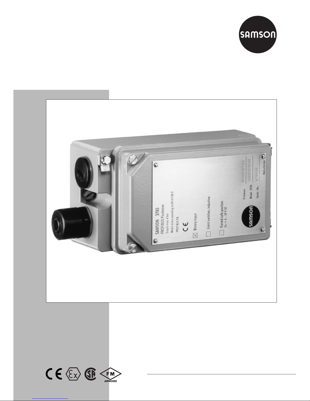
PROFIBUS Positioner
Type 3785
PA device profile version 2.0
Mounting and
Operating Instructions
EB 8382-1 EN
Firmware version R 1.4x/K 1.6x
Edition July 2004
Fig. 1 · Type 3785 PROFIBUS Positioner

Contents Page
1 Design and principle of operation . . . . . . . . . . . . . . . . . . . 8
1.1 Optional accessories . . . . . . . . . . . . . . . . . . . . . . . . . . 8
1.2 Communication. . . . . . . . . . . . . . . . . . . . . . . . . . . . . 8
2 Attaching the positioner. . . . . . . . . . . . . . . . . . . . . . . . 10
2.1 Direct attachment to Type 3277 Actuator . . . . . . . . . . . . . . . . 10
2.2 Attachment according to IEC 60534-6 . . . . . . . . . . . . . . . . . 14
2.2.1 Mounting sequence . . . . . . . . . . . . . . . . . . . . . . . . . . 14
2.2.2 Presetting the valve travel . . . . . . . . . . . . . . . . . . . . . . . 16
2.3 Attachment to rotary actuators . . . . . . . . . . . . . . . . . . . . . 18
2.3.1 Mounting the cam follower roll lever . . . . . . . . . . . . . . . . . . 18
2.3.2 Mounting the intermediate piece . . . . . . . . . . . . . . . . . . . . 18
2.3.3 Aligning and mounting the cam disk . . . . . . . . . . . . . . . . . . 20
2.3.4 Reversing amplifiers for double-acting actuators . . . . . . . . . . . . 22
2.4 Fail-safe position of the actuator . . . . . . . . . . . . . . . . . . . . 22
3 Connections. . . . . . . . . . . . . . . . . . . . . . . . . . . . . . 24
3.1 Pneumatic connections. . . . . . . . . . . . . . . . . . . . . . . . . 24
3.1.1 Pressure gauges. . . . . . . . . . . . . . . . . . . . . . . . . . . . 24
3.1.2 Supply air pressure . . . . . . . . . . . . . . . . . . . . . . . . . . 25
3.2 Electrical connections . . . . . . . . . . . . . . . . . . . . . . . . . 25
3.2.1 Forced venting . . . . . . . . . . . . . . . . . . . . . . . . . . . . 27
3.2.2 Limit switches . . . . . . . . . . . . . . . . . . . . . . . . . . . . . 28
3.2.3 Establishing communication (bus address) . . . . . . . . . . . . . . . 28
3.2.4 Local interface (SSP) . . . . . . . . . . . . . . . . . . . . . . . . . . 28
4 Operation . . . . . . . . . . . . . . . . . . . . . . . . . . . . . . 30
4.1 LED controls. . . . . . . . . . . . . . . . . . . . . . . . . . . . . . 30
4.2 Write protection. . . . . . . . . . . . . . . . . . . . . . . . . . . . 31
4.3 Activate/deactivate forced venting . . . . . . . . . . . . . . . . . . . 31
4.4 Default settings . . . . . . . . . . . . . . . . . . . . . . . . . . . . 31
4.4.1 Adjusting mechanical zero. . . . . . . . . . . . . . . . . . . . . . . 32
4.4.2 Initialization. . . . . . . . . . . . . . . . . . . . . . . . . . . . . . 32
4.5 Adjusting the inductive limit switches . . . . . . . . . . . . . . . . . . 34
5 Maintenance . . . . . . . . . . . . . . . . . . . . . . . . . . . . . 35
6 Servicing explosion-protected devices . . . . . . . . . . . . . . . . . 35
2 EB 8382-1 EN
Contents

7 How to implement a Class 1 PROFIBUS Master . . . . . . . . . . . . 36
7.1 Device database files (GSD) . . . . . . . . . . . . . . . . . . . . . . 36
7.2 Data exchange . . . . . . . . . . . . . . . . . . . . . . . . . . . . 36
7.3 Parameter description . . . . . . . . . . . . . . . . . . . . . . . . . 40
7.4 Coding of measured value status . . . . . . . . . . . . . . . . . . . . 42
7.5 Operating modes . . . . . . . . . . . . . . . . . . . . . . . . . . . 44
8 List of parameters. . . . . . . . . . . . . . . . . . . . . . . . . . . 47
9 Messages and diagnostics. . . . . . . . . . . . . . . . . . . . . . . 61
9.1 Diagnostic messages . . . . . . . . . . . . . . . . . . . . . . . . . 61
9.2 Extended diagnostic messages . . . . . . . . . . . . . . . . . . . . . 63
9.3 CHECKBACK messages . . . . . . . . . . . . . . . . . . . . . . . . 64
9.4 Messages during initialization . . . . . . . . . . . . . . . . . . . . . 66
Dimensional drawing . . . . . . . . . . . . . . . . . . . . . . . . . 69
Certificates . . . . . . . . . . . . . . . . . . . . . . . . . . . . . . 70
EB 8382-1 EN 3
Contents
4
The device is to be assembled, started up or operated only by trained and experienced personnel familiar with the product.
According to these mounting and operating instructions, trained personnel is
referred to as individuals who are able to judge the work they are assigned to
and recognize possible dangers due to their specialized training, their knowledge and experience as well as their knowledge of the applicable standards.
4
Explosion-protected versions of this device are to be operated only by personnel who have undergone special training or instructions, or who are authorized to work on explosion-protected devices in hazardous areas.
4
Any hazards that could be caused in the positioner by the process medium,
the operating pressure, the signal pressure or by moving parts are to be prevented by means of the appropriate measures.
If inadmissible motions or forces are produced in the pneumatic actuator as a
result of the supply air pressure level, the pressure must be restricted using a
suitable supply pressure reducing station.
4
Proper shipping and storage are assumed.
4
Note! Devices with a CE marking fulfil the requirements of the Directives
94/9/EC and 89/336/EEC. The declaration of conformity is available at
http://www.samson.de and on request.
!

Modifications of the firmware compared to the previous version
Old New
Control R 1.23 R 1.31
Firmware adaptation for a new hardware version
Hardware version device index .01
Control R 1.31 R 1.4
Actuator type When the actuator type is switched from "linear actuator" to "rotary actua-
tor", the following applies:
Initialization method . . . Based on maximum range
Transmission code . . . . 590
Nominal angle . . . . . 90°
End position for w < . . . 1 %
End position for w > . . . 99 %
Rot. angle range starts at 0°
Rot. angle range ends at 90°
When the actuator type is switched from "rotary actuator" to "linear actuator", the following applies:
Attachment . . . . . . . Integral . . . . . . . . . NAMUR
Initialization method . . . Based on nominal range . Based on nom. range
Mounting position: arrow Towards actuator . . . . Away from actuator
Transmission code . . . . D1 . . . . . . . . . . . –
Pin position . . . . . . . – . . . . . . . . . . . . A
Rated travel . . . . . . . 15 mm . . . . . . . . . 15 mm
End position for w < . . . 1 % . . . . . . . . . . . 1 %
End position for w > . . . 125 % . . . . . . . . . 125 %
Lower travel range value. 0 mm . . . . . . . . . . 0 mm
Upper travel range value 15 mm . . . . . . . . . 15 mm
Lever length . . . . . . . – . . . . . . . . . . . . 42 mm
Initialization method When the initialization method is switched from "maximum range" to "nomi-
nal range", the following applies:
End position for w < 1% End position for w > 125 %
When the initialization method is switched from "nominal range" to "maximum range", the following applies:
End position for w < 1% End position for w > 99 %
Desired transit time
open/closed
The adjustment range of the desired transit time is now limited to 75 s.
Initialization During initialization, the minimum control pulses are determined for 20 % to
80 % of the manipulated variable range and saved in the EEPROM.
Proportional-action
coefficients
KP_Y1 and KP_Y2
The coefficients are adapted to the selected actuator type and the measured
transit times.
4 EB 8382-1 EN
Firmware modifications

Control R 1.41 R 1.42
Correction when zero calibration was triggered by communication.
Communication K 1.34 K 1.41
Firmware adaptation for new hardware version
Hardware version device index .01
Communication 1.41 K 1.51
Bit 7 of the CHECKBACK parameter indicates the current status of control
loop monitoring. In contrast to bit 13, bit 7 is automatically reset when control
loop monitoring detects no further errors. The function of bit 13 remains unchanged. Messages issued by bit 7 are only supported with firmware version
R 1.41 and higher.
The "warm start" message indicated by bit 11 of the DIAGNOSIS parameter
is automatically reset after 10 s.
In Local Override mode, bit 2 of the CHECKBACK parameter is activated.
Communication 1.51 K 1.60
A bad set point status no longer causes the positioner to move the valve to
fail-safe position in any case. Rather, the positioner's behavior is determined
by the FSAVE_TYPE parameter.
Using the serial interface, the positioner can be configured and operated with
SAMSON's TROVIS-VIEW Configuration and Operator Interface software.
EB 8382-1 EN 5
Firmware modifications

Positioner
Travel
Direct attachment Type 3277
Acc. to IEC 60534-6 (NAMUR)
Adjustable
5 mm to 30 mm
5 mm to 255 mm or 30° to 120° for rotary actuators
Bus connection Fieldbus interface according to IEC 61158-2
Field unit according to FISCO (Fieldbus Intrinsically Safe Concept)
Permissible operating voltage 9 to 32 V DC; the specifications in the EC type examination certifi-
cate additionally apply to explosion-protected devices.
Voltage supplied over bus cable
Static destruction limit 35 V
Max. operating current 10 mA
Current in case of fault 0 mA
Auxiliary energy Supply pressure of 1.4 to 6 bar (20 to 90 psi)
Air quality according to ISO 8573-1:2001, i.e. max. particle size
and density: Class 4; oil content: Class 3;
pressure dew point: Class 3 or at least 10 K above lowest ambient
temperature to be expected
Signal pressure (output) 0 bar up to supply air pressure
Adjustable characteristic Linear, equal percentage, reverse equal percentage, user-defined
Deviation from characteristic≤1 %
Dead band Adjustable from 0.1 to 10.0 %, default 0.5 % (based on rated
travel/angle)
Resolution < 0.05 % (internal measurement)
Desired transit time Up to 75 s, separately adjustable for exhaust and supply air
Direction of action Reversible, adjusted using software
Air consumption Independent of supply air < 90 l
n
/h
Air supply
Actuator pressurized for Δp = 6 bar: 9.3 mn³/h, for Δp = 1.4 bar: 3.5 mn³/h
Actuator vented for Δp = 6 bar: 15.5 m
n
³/h, for Δp = 1.4 bar: 5.8 mn³/h
Permissible ambient temperature
–40 °C to 80 °C, the specifications in the EC type examination
certificate additionally apply to explosion-protected devices
Influences Temperature:≤0.15 %/10 K, auxiliary energy: none
Vibration: none up to 250 Hz and 4 g
Explosion protection II 2 G EEx ia IIC T6 acc. to ATEX, see EC type examination certificate
Degree of protection IP 65 using the included filter check valve
Electromagnetic compatibility Requirements acc. to EN 61000-6-2, EN 61000-6-3 and NE 21 met
Binary input Internal power supply 5 V DC,
R
i
= 100 kΩfor alarm function, e.g. connection of pressure switch
6 EB 8382-1 EN
Technical data

Forced venting
Input
K
V
coefficient
To be activated using switch inside the positioner
6 to 24 V DC, static destruction limit 45 V
R
i
approx. 6 kΩat 24 V DC (depending on voltage)
Switching point for "1" signal at≥3 V, switching point for "0" signal
only at 0 V
0.17
Communication Data transmission acc. to PROFIBUS-PA, Profile Class B, version 2.0
acc. to DIN EN 50170 and DIN 19245, Part 4 (version 3.0 also
available)
Local interface SAMSON SSP interface for configuration and start-up
Bus address Adjustable using software or microswitch, default upon delivery: 126
Accessories
Inductive limit switches Two Type SJ2SN proximity switches
For connection to switching amplifier according to EN 60947-5-6
Materials
Housing Die-cast aluminum, chromated and plastic-coated
External parts Stainless steel 1.4571 and 1.4301
Weight Approx. 1.3 kg
Positioner versions
Type 3785– XXXXX
3
X
Explosion
protection
Without
Ex II 2 G Ex ia IIC T6 acc. to ATEX
With Ex ia CSA/FM
Ex II 3 G Ex nA II T6 acc. to ATEX
0
1
3
8
Accessories Limit switches Without
2 inductive
0
22
Forced venting Without
With
0
12
PA device profile Version 2.0
Version 3.0
0
1
Pneumatic
connections
NPT ¼-18
ISO 228/1-G ¼
1
2
Electrical
connections
Cable gland M 20 x 1.5 with shielding,
nickel-plated brass
Quantity: 1
Quantity: 2
1
2
EB 8382-1 EN 7
Technical data

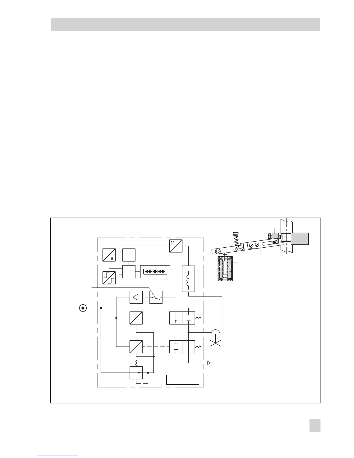
1 Design and principle of opera-
tion
The digital PROFIBUS-PA positioner is designed for attachment to pneumatic control
valves. It is used to assign the valve stem position (controlled variable) to the control signal (reference variable). It compares the digital output signal to the travel of the control
valve and generates a corresponding pressure signal as the output variable. As a result, the positioner requires auxiliary supply
air with a pressure of 1.4 to 6 bar. The necessary electrical power is supplied by the bus
of the PROFIBUS-PA segment based on
IEC 61158-2 standard transmission technology.
The positioner consists of an inductive,
contactless travel pick-off system and an
electrically controlled valve block comprising
two on/off valves and an electronic unit. This
unit contains two microcontrollers for processing the control algorithm and managing
PROFIBUS communication.
If a deviation between the actual valve travel
(actual value) and the reference variable (set
point) occurs, the microcontroller produces
binary pulse-pause modulated signals to
control the two on/off valves, each of which
is assigned a downstream amplifier. One of
these valves controls the exhaust air, the
other the supply air.
The supply air valve (3) controls the connection between the supply air (7, supply air
pressure 1.4 to 6 bar) and the actuator
(pressurizing). The exhaust air valve (4) controls the air exhausted from the actuator to
the atmosphere (venting). The on/off valves
can either have the switching states ("permanently open", "permanently closed" or gen-
erate single pulses of changing widths). The
two valves cause the plug stem to move to a
position corresponding to the reference variable. If there is no system deviation, both the
supply air valve and the exhaust air valve
are closed.
By default, the positioner is equipped with a
binary input for floating contacts, which additionally signals the switching state of a
further field device via PROFIBUS.
Activating the write protection switch, which
is located next to the bus address in the
hinged lid, prevents the positioner settings
from being overwritten by PROFIBUS communication.
Positioner with forced venting function:
The positioner is controlled by a 6 to 24 V
signal, causing the signal pressure to be applied to the actuator. If this voltage signal decreases, the signal pressure is shut off and
the actuator is vented. The springs in the actuator move the valve to its fail-safe position.
The forced venting function is included in all
positioners and can be activated/deactivated
as required over a switch. Refer to section 4.3 for details.
1.1 Optional accessories
As a supplement to the standard positioner
version, the positioner can be equipped with
limit switches. Two proximity switches can be
used to indicate the valve's end positions in
safety-related circuits.
1.2 Communication
The positioner is completely controlled by
digital signal transmission according to the
PROFIBUS-PA Profile Class B based on
8 EB 8382-1 EN
Design and principle of operation
DIN EN 50170 and DIN 19245, Part 4.
Data is transmitted as bit-synchronous current modulation at a transmission rate of
31.25 kbit/s over twisted-pair cables according to IEC 61158-2. Positioners are generally set up using a PC. One or more
positioners are connected to the PC's
PROFIBUS segment via segment coupler.
After mechanically resetting the positioner to
zero, it can be automatically started up using
an initialization routine. During initialization,
zero is automatically adjusted and the preset
span is checked.
The positioner is delivered with a standard
configuration for a control valve with a rated
travel of 15 mm designed for integral
positioner attachment.
Customized configuration to adapt the
positioner to other actuators can only be carried out using communication.
Configuration
The positioner is configured and operated on
the PC over the SSP interface (13) using
TROVIS-VIEW. Alternatively, it can be configured and operated via a segment coupler,
e.g. using the COMMUWIN II user interface
(by Endress + Hauser) or the SIMATIC PDM
user interface (by SIEMENS).
During configuration, parameters such as
control characteristic, direction of action,
travel limitation, travel range, transit time
and alarms, can be entered.
EB 8382-1 EN 9
Design and principle of operation
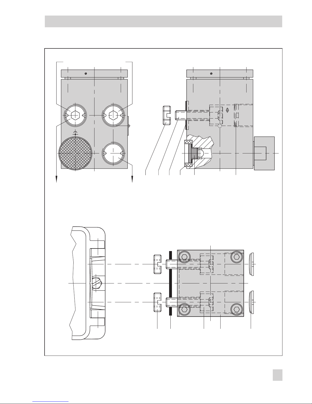
11
10
1
12
e
p
3
4
2
5
9
7
6
1
G
μC
61158-2
IEC
e
p
G
μC
PROFIBUS-PA
8
Serial Interface
13
Fig. 2 · Functional diagram
Binary input
Forced venting
Supply
air
Exhaust
air
1 Inductive travel pick-off
2 Microcontroller
3 On/off valve for supply air
4 On/off valve for exhaust air
5 Microcontroller
6 Switch for bus address and
write protection
7 Binary input
8 Forced venting
9 IEC 61158-2 interface module
10 Actuator stem
11 Lever
12 Clamp
13 SSP interface

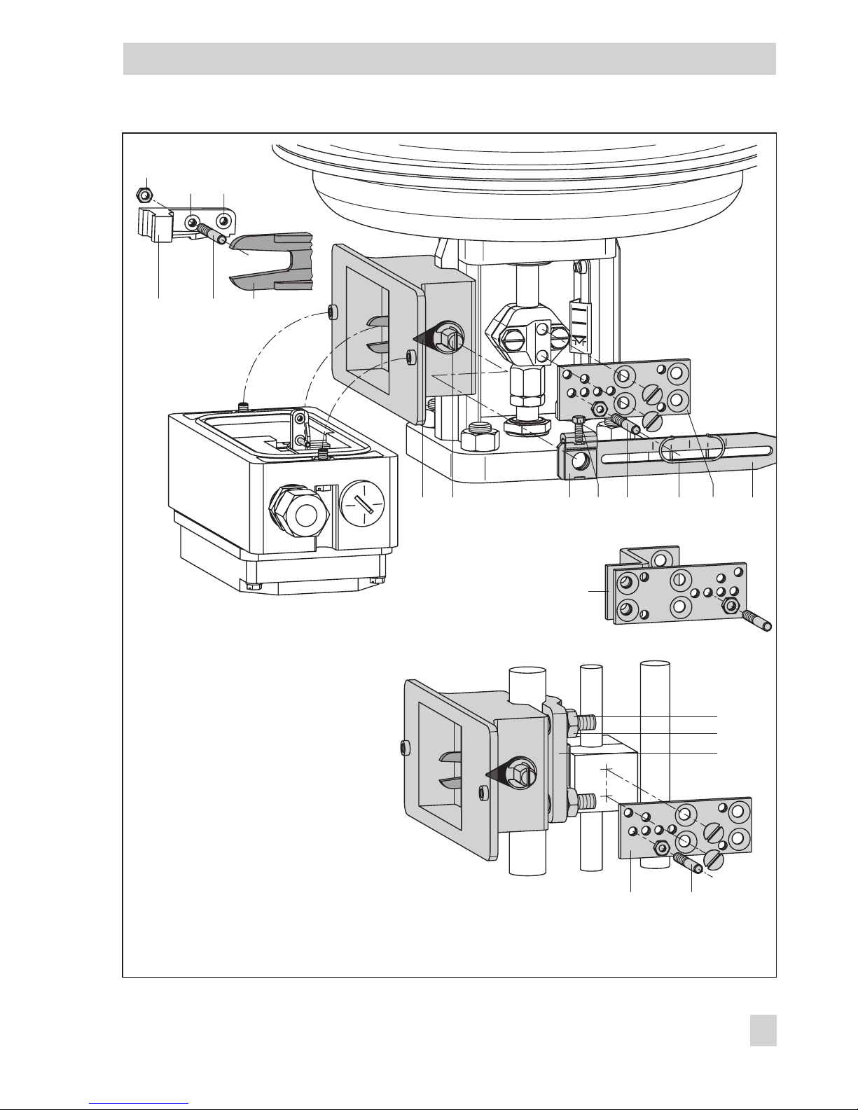
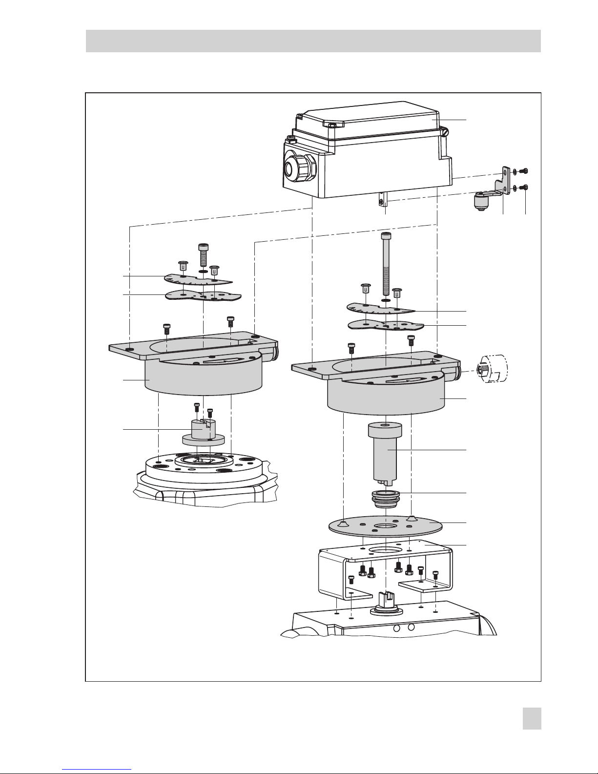
2 Attaching the positioner
The positioner can be attached either directly
to a SAMSON Type 3277 Actuator or according to NAMUR (IEC 60534-6) to control
valves with cast yokes or rod-type yokes.
In combination with an intermediate piece,
the positioner can also be attached as a rotary positioner to rotary actuators.
Since the standard positioner unit is delivered without accessories, refer to the corresponding tables for required mounting parts
and their order numbers.
Note!
For fast control valves with small travels
(transit time < 0.6 s), replace the filter in the
signal pressure output with a screw-in restriction, if necessary, to improve the control
properties. See also sections 2.1, 2.2 and
2.3.
Important!
The positioner does not have its own vent
plug so that the air is exhausted to the atmosphere through vent plugs located on the accessories (see also Figs. 3, 5 and 6).
A filter check valve for the exhaust air is included with each positioner (underneath the
transparent cover on the back of the
positioner).
Replace the standard vent plug included in
the accessories with this filter check valve.
This is necessary to achieve degree of protection IP 65 by preventing dirt and moisture
from entering the device.
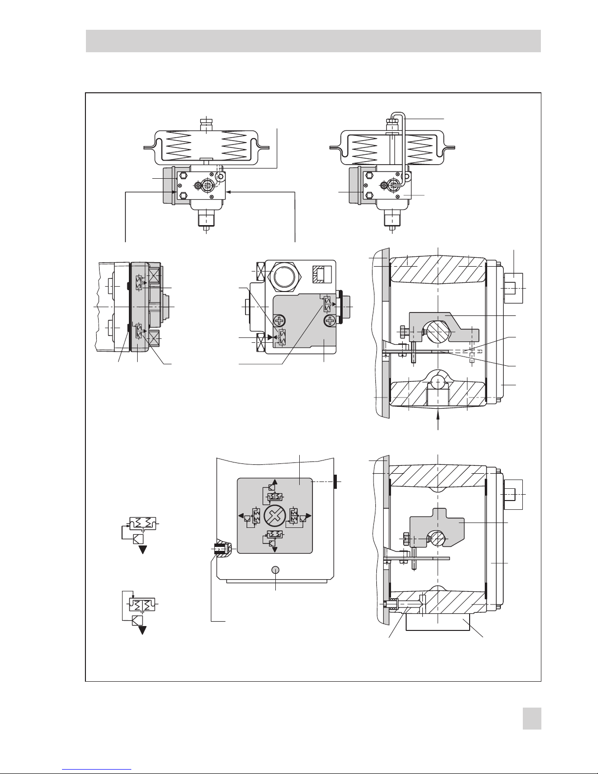
2.1 Direct attachment to
Type 3277 Actuator
For selection of the required mounting parts,
refer to Tables 1, 2 and 3 on page 13.
When looking at the signal pressure connection or the switchover plate (120 cm² actuator) from the top, the positioner must be attached to the left side of the actuator.
The arrow on the black housing cover
(Fig. 11) points towards the diaphragm
chamber.
Exception: control valves in which the plug
closes the seat area when the actuator stem
retracts. In this case, the positioner has to be
attached to the right side of the actuator, i.e.
with the arrow pointing away from the diaphragm chamber.
1. Screw clamp (1.2) to the actuator stem,
ensuring that the fastening screw is located in the groove of the actuator stem.
2. Screw associated lever D1 or D2 (for
700 cm² actuator) to the transmission lever of the positioner.
3. Fasten distance plate (15) with the seal
pointing towards the actuator yoke.
4. Place positioner on the plate so that the
pick-off lever D1 or D2 slides centrically
over the pin of the clamp (1.2). Screw
positioner to the distance plate (15).
5. Mount cover (16).
10 EB 8382-1 EN
Attaching the positioner
EB 8382-1 EN 11
Attaching the positioner
SUPPLY
1817 19
1.2
D2
D1
17
16
15
1.2
16
17
15
Fig. 3 · Attachment and signal pressure connection for Types 3277 (top) and 3277-5 with 120 cm² (bottom)
1.2 Clamp
D1 Lever
D2 Lever
15 Distance plate
16 Cover
17 Seal
18 Cover plate
19 Switch plate
Actuator stem
extends
Actuator stem
retracts
Switchover plate Signal pressure input
Marking
Signal pressure input with
brass restriction, if required
Signal pressure bore Switchover plate
Vent
Connection block
Side view of connection block
with seal (new) with switch plate (old)
Actuator stem extends Actuator stem retracts
Internal signal pressure
connection
Signal pressure
connection over piping
Symbol "Actuator
stem extends"
Marking
Symbol "Actuator
stem retracts"

240, 350 and 700 cm² actuators
6. Check whether the tongue of the
seal (17) is properly aligned at the side
of the connection block with the actuator
symbol "Actuator stem extends" or "Actuator stem retracts" to match the actuator
version used. If it does not match, remove
the three fastening screws and the cover
plate (18), turn the seal (17) by 180° and
reinsert it.
When the old connection block is used,
turn the switch plate (19) to align the arrow with the actuator symbol.
7. Place connection block with the associated sealing rings against the positioner
and the actuator yoke and screw it tight
using the fastening screw.
For actuators with fail-safe position "Actuator stem retracts", additionally mount
the prefabricated signal pressure line.
120 cm² actuator
For Type 3277-5 Actuators with 120 cm²,
the signal pressure is transmitted to the diaphragm chamber over the switchover plate
(see Fig. 3, bottom).
For a rated travel of 7.5 mm, a brass restriction (see Accessories table on page 13) must
be pressed into the seal located in the signal
pressure input on the actuator yoke.
With 15 mm rated travel, this is only required if the supply pressure exceeds 4 bar
6. Remove screw at the back of the
positioner and close the signal pressure
output (output 38) at the side with the associated plug included in the accessories
kit.
7. Mount positioner so that the bore in the
distance plate (15) is aligned with the
seal located in the bore of the actuator
yoke.
8. Align switchover plate with the corresponding symbol for attachment on the
left. Screw the plate to the actuator yoke.
Important!
If, in addition to the positioner, a solenoid
valve or a similar device is attached to the
120 cm² actuator, the rear M3 screw must
not be removed. In this case, the signal pressure has to be fed from the signal pressure
output to the actuator over the required connecting plate (see Table 2). The switchover
plate is no longer required.
Note!
For faster control valves with a transit time
< 0.6 s, replace the filter in the signal pressure output (output 38) with a screw-in
restriction (see Accessories table), if necessary.
Filling the spring chamber with air
If the Type 3277 Actuator's spring chamber
must be pressurized with the air exhausted
from the positioner, the spring chamber (version "Actuator stem extends") can be connected to the connection block using a tube
(Table 3). To do so, remove the plug on the
connection block.
With the Type 3277-5, version "Actuator
stem retracts", the spring chamber is constantly pressurized with the air exhausted
from the positioner through an internal bore.
12 EB 8382-1 EN
Attaching the positioner
Table 1
Required lever with associated clamp and distance plate
Actuator size
cm²
Mounting kit
Order no.
D1 (33 mm in length with clamp, 17 mm in height) 120 (G ¼)
120 (¼ NPT)
1400-6790
1400-6791
D1 (33 mm in length with clamp, 17 mm in height) 240 and 350 1400-6370
D2 (44 mm in length with clamp, 13 mm in height) 700 1400-6371
Table 2 Order no.
Switchover plate for 120 cm² actuator Actuator 3277-5xxxxxx.00 (old) 1400-6819
Switchover plate new Actuators with index .01 or higher (new) 1400-6822
Connecting plate for additional attachment
of, e.g. a solenoid valve
3277-5xxxxxxxx.00 G
1
8
(old)
1
8
NPT
1400-6820
1400-6821
Connecting plate new Actuators with index .01 or higher (new) 1400-6823
Note! Only new switchover plates and connecting plates can be used with the new actuators (modifica-
tion index .01). Old and new plates are not interchangeable.
Connection block required for actuator sizes 250, 350 and
700 cm² (including seals and fastening screw)
G ¼
¼ NPT
1400-8811
1400-8812
Table 3 Actuator size cm² Material Order no.
Required tubes including fittings 240 Steel 1400-6444
240 Stainless steel 1400-6445
For version
"Actuator stem retracts"
or
when pressurizing the upper diaphragm
chamber
350 Steel 1400-6446
350 Stainless steel 1400-6447
700 Steel 1400-6448
700 Stainless steel 1400-6449
Accessories Order no.
Pressure gauge mounting kit for supply air and signal pressure St. steel/brass
St. steel/St. steel
1400-6957
1400-6958
Signal pressure restrictions (screw-in and brass restriction) 1400-6964
Filter check valve, replaces vent plug and increases degree of protection to IP 65
(one included with every positioner delivered)
1790-7408
EB 8382-1 EN 13
Attaching the positioner

2.2 Attachment according to
IEC 60534-6
For selection of the required mounting
parts, refer to Tables 4 and 5 on page 17.
For positioner attachment according to
NAMUR as shown in Fig. 4, an adapter
housing is required. The valve travel is transmitted over the lever (18) and shaft (25) to
the bracket (28) of the adapter housing and
then to the pin (27) located on the positioner
lever.
To attach the positioner, the mounting parts
listed in Table 4 are required. Which lever is
to be used depends on the rated valve travel.
The positioner must be attached to the
adapter housing so that the arrow on the
black housing cover points away from the diaphragm actuator towards the valve.
Exception: control valves in which the plug
closes the seat area when the actuator stem
retracts. In this case, the arrow must point towards the diaphragm actuator.
If the adapter housing cannot be mounted
between the actuator and the valve (e.g.
non-SAMSON actuators), make sure the arrow on the housing cover points towards the
control valve.
Note!
For faster control valves with a transit time
< 0.6 s, replace the filter in the signal pressure output (output 38) with a screw-in restriction (see Accessories table), if necessary.
2.2.1Mounting sequence
Important!
Before mounting the parts, apply a signal
pressure to the actuator so that the valve is
set to 50 % of its travel. It is only in this position that the lever (18) and bracket (28) can
be aligned exactly.
Control valve with cast yoke
1. Use countersunk screws to attach the
plate (20) to the coupling that connects
the plug and actuator stem. For 2100
and 2800 cm² actuators, use additional
mounting bracket (32).
2. Remove rubber plug from the adapter
housing and fasten the housing to the
NAMUR rib using the hexagon head
screw.
Control valve with rod-type yoke
1. Screw plate (20) to the follower clamp of
the plug stem.
2. Screw studs (29) into the adapter housing.
3. Place housing with the plate (30) on either the right or left side of the valve rod
and screw the housing tight using
nuts (31). Align the height of the housing
so that the lever (18) to be mounted subsequently is horizontal.
4. Move clamp (21) to surround the
pin (19). Screw pin in the center row of
bores in the plate (20) and lock it so that
it will be located above the correct lever
marking (1 to 2) for the assigned travel
(see Table 5).
Intermediate values must be interpolated.
14 EB 8382-1 EN
Attaching the positioner
EB 8382-1 EN 15
Attaching the positioner
2
1,5
1
2826
AB
24 25 22
32
31
20 19
19 21 2023 18
27b
27a
29
30
Fig. 4 · Attachment according to IEC 60534-6 (NAMUR)
Mounting position
Attachment to
NAMUR rib
Attachment to rods
18 Lever N1, N2
19 Pin
20 Plate
21 Clamp
22 Clamping plate
23 Screw
24 Pointer
25 Shaft
26 Lever of positioner
27a Transmission pin
27b Lock nut
28 Bracket
29 Studs
30 Plate
31 Nuts
32 Mounting bracket

5. Measure distance between the center of
the shaft (25) and the center of the
pin (19). This value must later be entered
when configuring the positioner.
2.2.2Presetting the valve travel
1. Adjust shaft (25) in the adapter housing
so that the black pointer (24) is aligned
with the cast marking on the adapter
housing.
2. Screw clamping plate (22) tight in this
position using a screw (23).
3. Screw in pin (27) at the positioner lever (26) on the side of the insert nuts and
secure it with a hex nut on the opposite
side. Observe mounting position A or B
according to Table 5 and Fig. 5.
4. Place positioner on the adapter housing
such that the transmission pin (27a) lies
properly within the arms of the
bracket (28). To do so, insert a 2.5 mm
Allen wrench or screwdriver from the
front into the bore located below the oblong hole on the cover plate and push the
positioner lever to the required position.
5. Screw positioner to the adapter housing.
6. Relieve actuator of the signal pressure.
16 EB 8382-1 EN
Attaching the positioner
Table 4 Attachment IEC 60534-6
Control valve Travel [mm] With lever Order no.
NAMUR mounting kit
Parts, see Fig. 4
Valve with cast yoke
7.5 to 60
N1 (125 mm)
1400-6787
30 to 120
N2 (212 mm)
1400-6789
Valve with
rod-type
yoke,
rod diame
-
ter [mm]
20 to 25 N1 1400-6436
20 to 25 N2 1400-6437
25 to 30 N1 1400-6438
25 to 30 N2 1400-6439
30 to 35 N1 1400-6440
30 to 35 N2 1400-6441
Attachment to linear Fisher and Masoneilan actuators
(one each of both mounting kits is needed per actuator)
1400-6771
and
1400-6787
Accessories Order no.
Pressure gauge mounting block G ¼
¼ NPT
1400-7106
1400-7107
Pressure gauge mounting kit (output and supply)
Order with every pressure gauge kit: 2 restrictions (1790-6121)
St. st./Brass
St. st./St. st.
1402-0938
1402-0939
Signal pressure restrictions (screw-in and brass restrictions) 1400-6964
Filter check valve, replaces vent plug and increases degree of protection to IP 65
(one included with every positioner delivered)
1790-7408
Table 5 Attachment acc. to IEC 60534-6
Travel in mm*
7.5 15 15 30 30 60 30 60 60 120
Pin on marking* 1 1 2 1 2 1 2 1 2
Corresp. distance pin to lever fulcrum 42 42 84 42 84 84 168 84 168
With lever N1 (125 mm long) N2 (212 mm long)
Transmission pin (27) on position A A B A B
* Deviating travel values (intermediate values) are to be interpolated accordingly
EB 8382-1 EN 1
7
Attaching the positioner

2.3 Attachment to rotary actuators
For selection of the required mounting
parts, refer to Table 6 on page 21.
The positioner can also be attached to rotary
actuators in accordance with VDI/VDE 3845
using the mounting parts and accessories
listed in Table 6. In this arrangement, the actuator's rotary motion is converted via the
cam disk on the actuator shaft and the follower roll of the positioner lever to a linear
motion required by the positioner's inductive
travel pick-off system.
Each cam disk is suitable for two curves: for
angles of rotation from 0° to 90° (for all angles smaller than 90°) and for 0° to 120°
(for all angles of 90° and larger).
For double-acting, springless rotary actuators, it is necessary to connect a reversing
amplifier to the connection side of the
positioner (see section 2.3.4).
If the positioner is attached to a SAMSON
Type 3278 Rotary Actuator, the positioner's
exhaust air is routed to the inside of the actuator and the chamber behind the diaphragm. No additional tubing is required.
If the positioner is attached to non-SAMSON
actuators (NAMUR), the air is applied to the
chamber behind the diaphragm through a
tube assembly and a tee, connected between
the actuator and the exhaust connection of
the intermediate piece.
Note!
For faster control valves with a transit time
< 0.6 s, replace the filter in the signal pressure output (output 38) with a screw-in restriction (see Accessories table), if necessary.
2.3.1Mounting the cam follower
roll lever
1. Place lever with the attached roll (35) on
the transmission lever (37) and secure it
with the enclosed screws (38) and washers.
2.3.2Mounting the intermediate
piece
SAMSON Type 3278 Actuator
1. Screw adapter (36) to the free end of the
rotary actuator shaft using two screws.
2. Place the positioner's intermediate
piece (34) on the actuator housing and
secure it using two screws. Align intermediate piece so that the air connections of
the positioner face towards the diaphragm case side.
Non-SAMSON actuators
1. Position complete intermediate piece (34,
42, 44 and 45) on the bracket (fixing
level 1, VDI/VDE 3845) delivered with
the actuator and fasten it with screws.
2. Align cam disk (40) and scale according
to section 2.3.3 and fasten them with
screws.
With springless actuators, the reversing amplifier (45) must be screwed to the side of the
positioner housing. Refer to section 2.3.4 for
details.
18 EB 8382-1 EN
Attaching the positioner
EB 8382-1 EN 19
Attaching the positioner
33
3835
39
39
40
34
36
40
34
44
45
42
43
37
Fig. 5 · Attachment to rotary actuators
Attachment to
SAMSON Type 3278 Actuator
Attachment acc. to
VDI/VDE 3845
Vent plug or
filter check valve
33 Positioner
34 Intermediate piece
35 Lever with cam follower roll
36 Adapter
37 Transmission lever
38 Screws
39 Scale
40 Cam disk
41 Actuator shaft
42 Plate
43 Bracket
44 Coupling
45 Seal

2.3.3Aligning and mounting the
cam disk
In rotary actuators with spring-return mechanism, the built-in actuator springs determine
the fail-safe position and the direction of rotation of the control valve (clockwise,
counterclockwise).
With double-acting, springless rotary actuators, the direction of rotation depends on
both the actuator and the valve model used.
Close the valve before making any adjust-
ments.
The positioner's direction of action, i.e.
whether the valve opens or closes when the
reference variable increases, has to be software-adjusted using communication (increasing/increasing or increasing/decreasing).
1. Position cam disk with scale on the
adapter (36) or the coupling (34) and
fasten the screw loosely at first.
The cam disk carries two cam sections. The
starting point of each section is marked by a
small bore.
Important!
With the valve closed, the starting point
(bore hole) of the respective curve is to be
aligned so that the center of rotation of the
cam disk, the 0° position on the scale, and
the arrow mark on the plate are aligned.
The starting point for the closing position
must not be below 0° position!
In actuators with fail-safe position "Control
valve open" (OPEN), pressurize the actuator
with the max. signal pressure before aligning
the cam disk.
In springless actuators, connect the supply
air.
2. On aligning the cam disk, the double-sided scale disk must be clipped on
so that the value on the scale corresponds to the control valve's direction of
rotation. Tightly secure the cam disk with
the fastening screws now.
Securing the aligned cam disk
If you want to additionally secure the cam
disk to prevent it from being turned, proceed
as follows:
Four bore holes are located centrically
around the center bore on the cam disk. Select a suitable hole to secure the cam disk.
Through this hole, drill a hole in the
adapter (36) or coupling (44) and insert a
2 mm dowel pin.
3. Attach positioner to the intermediate
piece (34) so that the lever (35) contacts
the cam disk with its cam follower roll. To
do so, insert a 2.5 mm Allen wrench or
screwdriver from the front into the bore
located below the oblong hole on the
cover plate and push the positioner lever
to the required position.
4. Screw positioner to the intermediate
piece.
20 EB 8382-1 EN
Attaching the positioner
Table 6 Rotary actuators (complete mounting parts, but without cam disk)
Attachment acc. to
VDI/VDE 3845,
level 1
SAMSON Type 3278 Actuator Attachment to Masoneilan actuators
160 cm²
actuator
320 cm²
actuator
Camflex I
DN 25 to 100
Camflex I
DN 125 to 250
Camflex II
Order no.
1400-8815 1400-7103 1400-7104 1400-7118 1400-7119 1400-7120
Piping kit, 8 x 1 stainless steel
G: 1400-6670 G: 1400-6672
NPT: 1400-6669 NPT: 1400-6671
Accessories Order no.
Reversing amplifier for springless double-acting actuators G: 1079-1118 NPT: 1079-1119
Cam disk (0050-0089) with accessories, angle of rotation 0° to 90° and 0° to 120° 1400-6959
Cam disk (0050-0089) esp. for VETEC, adjustable by software from 0° to 75° 1400-6960
Cam disk (0050-0090) esp. for Camflex, adjustable by software from 0° to 50° 1400-6961
Pressure gauge mounting block G ¼: 1400-7106 ¼ NPT: 1400-7107
Pressure gauge set Stainl. steel/Br:
1400-6957
St. steel/st. steel:
1400-6958
Signal pressure restrictions (screw-in and brass restrictions) 1400-6964
Filter check valve, replaces vent plug and increases degree of
protection to IP 65 (one included with every positioner delivered)
1790-7408
EB 8382-1 EN 21
Attaching the positioner
Fig. 6 · Aligning the cam disk
Cam follower roll
Starting point
Bore holes to secure
the cam disk
Insert clip and press
tongues outward.
View onto actuator shaft from positioner
Control valve opens counterclockwise Control valve opens clockwise

2.3.4Reversing amplifiers for double-acting actuators
For the use with double-acting actuators, the
positioner must be fitted with a reversing amplifier. The reversing amplifier is listed as an
accessory in Table 6 on page 21.
The signal pressure of the positioner is supplied at output A1 of the reversing amplifier.
An opposing pressure, which equals the required supply pressure when added to the
pressure at A
1
, is applied at output A2. The
rule A
1
+ A2= Z applies.
Mounting
1. Screw special nuts (1.3) from the acces-
sories of the reversing amplifier into the
threaded connections of the positioner.
2. Remove sealing plug (1.5) from the re-
versing amplifier. The rubber seal (1.4)
must remain installed.
3. Insert gasket (1.2) into recess of the re-
versing amplifier and push both hollow
special screws (1.1) into the connection
bores A1 and Z.
4. Place reversing amplifier onto the
positioner and screw tight using both
special screws (1.1).
5. Replace vent plug in the reversing ampli-
fier with the included filter check valve.
Signal pressure connections
A
1
: Connect output A1to the signal pressure
connection at the actuator that opens the
valve when the pressure increases.
A
2
: Connect output A2to the signal pressure
connection at the actuator that closes the
valve when the pressure increases.
4
Set up the actuator as "Double-acting
without spring-return mechanism" in the
user interface under Start-up -> Actuator
type.
2.4 Fail-safe position of the actuator
Important!
If the fail-safe position of the actuator is
changed subsequently by modifying the actuator springs from "Actuator stem extends" to
"Actuator stem retracts", readjust mechanical
zero and re-initialize the positioner.
22 EB 8382-1 EN
Attaching the positioner
EB 8382-1 EN 23
Attaching the positioner
1.3 1.2 1.1 1
Output 38 Supply 9
A
1
1.5 1.6
Z
A
2
1.4
A
1
A
2
Output 38 Supply 9
1.3 1.21.1
1.6
Z
A
1
Fig. 7 · Mounting a reversing amplifier
From the positioner
Control signals
to the actuator
1 Reversing amplifier
1.1 Special screws
1.2 Gasket
1.3 Special nuts
1.4 Rubber seal
1.5 Plug
1.6 Filter
3 Connections
3.1 Pneumatic connections
The air connections are either ¼ NPT or G ¼
tapped holes. Common fittings for metal and
copper tubes or plastic hoses can be used.
Important!
The supply air must be dry and free of oil
and dust. The maintenance instructions for
upstream pressure reducing stations must be
observed. Carefully purge all air tubes and
hoses before connecting them.
If the positioner is attached directly to the
Type 3277 Actuator, the connection of the
signal pressure to the actuator is fixed. For
NAMUR attachment, the signal pressure can
be applied to either the upper or lower diaphragm chamber of the actuator, depending
on the actuator's fail-safe action (either "Actuator stem retracts" or "stem extends").
Exhaust air: The exhaust air connection of
the positioner is located on the mounting kit.
For direct attachment, a vent plug is located
on the plastic cover of the actuator. For
NAMUR attachment, the vent plug can be
found at the adapter housing. For attachment
to rotary actuators, it is either located either
on the intermediate piece or the reversing
amplifier.
To guarantee degree of protection IP 65, the
vent plug must be replaced with the filter
check valve included with the positioner.
Refer to section 2 on page 10 (Important!)
for details.
3.1.1Pressure gauges
To monitor positioner operation, it is recommended to connect pressure gauges for the
supply air and signal pressure. The required
gauges are listed as accessories in Tables 3,
4 or 6.
24 EB 8382-1 EN
Connections
2...3mm
Fig. 8 · Mounting pressure gauges
Nut Restriction with filter
Order no. 1790-6121

3.1.2Supply air pressure
The required supply air pressure depends on
the bench range and the operating direction
(fail-safe action) of the actuator. The bench
range is indicated on the nameplate as a
spring range or signal pressure range.
Actuator stem extends:
Required supply air pressure = upper bench
range value + 0.2 bar, at least 1.4 bar
Actuator stem retracts:
The required supply air pressure for
tight-closing valves is estimated on the basis
of the maximum signal pressure p
st max
:
p
st max
= F +
d² p p
4A
⋅⋅⋅Δ
[bar]
d = Seat diameter [cm]
Δp = Differential pressure across the valve [bar]
A = Actuator area [cm²]
F = Upper bench range value of actuator [bar]
If there are no specifications, calculate as
follows:
Required supply air pressure = upper bench
range value + 1 bar
3.2 Electrical connections
For electrical installation, you are required to observe the relevant
electrotechnical regulations and the
accident prevention regulations that
apply in the country of use. In Germany, these are the VDE regulations
and the accident prevention regulations of the employers’ liability insurance.
The following regulations apply for
installation in hazardous areas:
EN 60079-14:2003; VDE 0165
Part 1:1998 ”Electrical apparatus for
explosive gas atmospheres”, and
EN 50281-1-2: VDE 0165
Part 2:1999 ”Electrical apparatus for
use in the presence of combustible
dust”.
For intrinsically safe electrical equipment approved in accordance with
Directive 79/196/EEC, the data
specified in the certificate of conformity apply for the connection of intrinsically safe circuits. For intrinsically safe electrical equipment approved in accordance with Directive
94/9/EC, the data specified in the
EC type examination certificate apply
for the connection of intrinsically safe
circuits.
Caution! The terminal assignment
specified in the certificate must be
observed! Switching the assignment
of the electrical terminals may cause
the explosion protection to become
ineffective! Do not loosen enameled
screws in or on the housing.
EB 8382-1 EN 25
Connections
!

Note on the selection of cables and wires
To run several intrinsically safe circuits in one
multi-core cable, observe section 12 of
EN 60079-14; VDE 0165:1998.
Note especially that, for commonly used insulating materials such as polyethylene, the
radial thickness of the conductor insulation
must be at least 0.2 mm. The diameter of a
single wire of a flexible conductor must not
be smaller than 0.1 mm.
The conductor ends must be protected
against unlaying, e.g. by using wire-end ferrules. When two separate cables are used
for connection, an additional cable gland
can be installed.
Cable entries left unused must be sealed with
plugs.
Positioners used in ambient temperatures
down to –40 °C must be fitted with metal cable entries.
For terminal assignment, refer to Fig. 9 or to
the designations on the cover plate inside the
lid.
Cable entries
Cable entry with M20x1.5 cable gland, 7 to
12 mm clamping range.
There is a second M20x1.5 cable gland in
the housing that can be used for additional
connection, if required.
The screw terminals are designed for wire
cross-sections of 0.2 to 2.5 mm² (tightening
torque at least 0.5 Nm).
Bus line
The shielded PROFIBUS connecting cable
must be routed over the EMC-proof brass cable gland (standard) of the positioner to the
terminals. The shield, which is placed over
the clamping insert, is connected over a
large area to the gland and housing.
1. To connect the bus line, remove coupling
nut and clamping insert from the
positioner. Also remove the dust cap.
2. Slide coupling nut and clamping insert
over the connecting cable.
3. Strip insulation off the end of the bus line
to the required connecting length. Cut off
the wire shield up to a length of approx.
13 mm. If necessary, cut off any filling
cable cores as well.
4. Disentangle the braided shield and pull it
over the clamping insert.
5. Press clamping insert into connecting
screw gland. Tighten coupling nut until
the connecting cable is clamped tightly.
6. Route two-wire bus line to the screw ter-
minals marked "IEC 1158-2"; when doing so, no polarity has to be observed.
In exceptional cases, if the plant does not
permit such a connection, feed the cable
shield through the cable gland and connect it
to be capacitive over terminal "S". However,
make sure that no conducting connection occurs from the shield to the cable gland or
housing.
26 EB 8382-1 EN
Connections

Refer to PROFIBUS-PA User and Installation
Guideline (PROFIBUS User Organization
document 2.091) for further information.
At the binary input, a passive floating contact can be used. The positioner signals the
circuit's state using the bus protocol.
Important!
The connection of limit switches, binary input
and forced venting function requires an additional cable gland that must replace the
cap fitted on the housing.
Accessories: M20 x 1.5 cable gland,
nickel-plated brass, order no. 8808-0143
3.2.1Forced venting
For positioners with forced venting function,
a voltage of 6 to 24 V DC must be applied to
the associated terminals.
The forced venting function can be activated
or deactivated over an internal switch. See
section 4.3 for details.
Note!
If there is no voltage connected or when the
voltage signal is interrupted, the positioner
vents the actuator and does not respond to
the reference variable.
EB 8382-1 EN 27
Connections
Fig. 9 · Electrical connections (terminal assignment according to DIN 45140)
GW2 GW1
PE
S
NC
-52
+51
-42
+41 -86
+85
-82 +81
IEC 1158-2
PROFIBUS-PA
6...24 VDC
Brass cable gland Shielding Clamping insert Coupling nut
Switching amplifier
acc. to EN 60947-5-6
Bus line
Limit switches Binary input Forced venting

3.2.2Limit switches
Switching amplifiers have to be connected in
the output circuit to operate limit switches. To
ensure operational safety of the positioner,
these switching amplifiers must comply with
the limits of the control circuit according to
NAMUR. Observe the relevant regulations if
the positioner is installed in hazardous areas.
3.2.3Establishing communication
(bus address)
Communication between positioner, programmable logic controller or automation
system, i.e. between PC or workstation and
the positioner(s), is established using a segment coupler (see Fig. 10) in accordance
with the PROFIBUS guidelines.
If the positioner is used in hazardous areas,
exlosion-protected PROFIBUS-PA segment
couplers must be used.
A maximum of 32 positioners can be operated in parallel on a segment coupler in one
PROFIBUS-PA segment. In hazardous areas,
fewer positioners can be connected.
Each positioner in a segment must be assigned a unique bus address between 0
and 125. Seven microswitches located on the
inside of the positioner's hinged lid serve to
enter the bus address either directly by
switch numbers 1, 2, 4 etc. or by adding up
several switch positions. The positioner is delivered with the default address set to 126.
Make absolutely sure that the switches are
adjusted all the way to either 1 or 0, not set
to an intermediate position.
Note!
Start the positioner up again for a new bus
address to be adopted.
3.2.4Local interface (SSP)
The local interface is located on the inside of
the positioner's hinged lid. It is connected to
a PC over the serial interface adapter (order
no. 1400-7700). The positioner can be
started up using the interface and
SAMSON's TROVIS-VIEW software.
It is no longer necessary to connect the device to a PROFIBUS DP/PA segment. Only
the power supply needs to be connected over
the bus terminals of the positioner (any DC
voltage supply unit between 9 and 32 V).
The TROVIS-VIEW software and the device
module 3785 in version 2.02 are required.
The positioner can also be accessed over the
SSP interface when it is connected to a bus
segment.
Cyclic and acyclic data exchange are not affected. The value written last is always valid
for the device parameters.
28 EB 8382-1 EN
Connections

EB 8382-1 EN 29
Connections
PROFIBUS-DP(E) RS 485
3785
3785
3785
3785
PROFIBUS-PA IEC 61158-2
PROFIBUS-DP RS 485
3785-1
3785-1
3785-1
3785-1
PROFIBUS-PA IEC 61158-2
PROFIBUS-DP(E) RS 485
PROFIBUS-DP RS 485
Fig. 10 · PROFIBUS connection
Controller/PLC/control system
(Class 1 Master)
Display and control component
(Class 2 Master)
Segment coupler
Termination
Termination
Fig. 10.1 · Connection of Type 3785 Positioners
Fig. 10.2 · Connection of Type 3785-1 Positioners in hazardous areas
Controller/PLC/control system
(
Class 1 Master)
Display and control component
(
Class 2 Master)
Termination
Ex-proof segment coupler
Termination
Non-hazardous
area
Hazardous area

4 Operation
Warning!
Before putting the positioner into operation, carefully move the control
valve to its end position by covering
the hole (manually) on the cover plate
(Fig. 11). Check whether the lever
mechanism functions properly.
If the maximum angle of rotation is
exceeded by selecting the wrong lever mechanism or sizing the lever
mechanism incorrectly, the positioner
may be destroyed.
4.1 LED controls
Two LEDs located inside the cover serve to
monitor the positioner, indicating the
positioner's status during start-up, operation
and in the event of defects.
The colors indicate the following:
Red Start-up or error, no control
operation possible
Green No error recognized, control
operation or fail-safe position
(e.g. if not initialized)
Red + Green Error recognized, control
operation possible
For details, refer to the table below.
30 EB 8382-1 EN
Operation
!
Description LED
Positioner start-up Red ON
No errors
Positioner connected to bus, cold start performed, initialization required
When initializing or adjusting zero
Positioner initialized, no valid set point
Positioner initialized, valid set point, control operation
Green, generally
Green blinks slowly
Green blinks quickly
Green blinks 3 times quickly + long pause
Green ON
Errors during control operation
Zero point error
Control loop error
Red and green
Red and green blink slowly
Red and green blink quickly
Errors causing the first initialization to be canceled
(positioner does not start standard operation)
Zero point error
Error in mechanics/pneumatics section
Control loop error
Red, generally
Red blinks slowly
Red ON
Red blinks quickly
Errors causing the positioner to stop control operation
Positioner recognized an internal error Red blinks 3 times quickly + long pause

4.2 Write protection
A microswitch marked "write protection" is
located to the right of the seven bus address
selector switches inside the hinged cover.
When it is activated (position ON), the
positioner settings are write-protected so that
they cannot be overwritten by the PROFIBUS
communication protocol. If you want to
change the settings via communication, set
the switch to position OFF.
4.3 Activate/deactivate forced
venting
For model index .03 and higher:
1. Remove four screws from the cover inside
the hinged lid and remove the cover.
2. Remove screw in the middle of the
printed circuit board and turn the PCB to
one side.
3. Set switch to desired position:
1 ENABLED > function activated
2 DISABLED > function deactivated
4.4 Default settings
All parameters are set to their default values.
Refer to section 8 for descriptions of the parameters.
Caution!
Manual operation and activated end
position function can cause the actuator to be pressurized with the maximum supply pressure. If this causes
inadmissible forces, restrict the supply
pressure using a suitable pressure reducing station.
EB 8382-1 EN 31
Operation
GW1
GW2
3785
PE
IEC 1158-2
S
NC -52
+51
-42
+41
-86
+85
-82
+81
LED 1
LED 2
1
2
4
8
16
32
64
Write protection
Caution!
Valve
actuates
Init/Zero
Bus address
10
0N0FF
0
Fig. 11 · Inside view of the cover plate
Arrow for
mounting position Pointer Manual operation Bus address Write protection switch
Zero point lever Metal tags Adjustment screws LEDs Key for initialization
for limit switches or zero adjustment
!

4.4.1Adjusting mechanical zero
Important!
Zero must be adjusted with the valve closed
(for three-way valves with the actuator stem
extended).
4
Firmly push the zero point lever, which is
located on the cover plate of the
positioner, once in the direction indicated
by the arrow as far as it will go. The yellow pointer will then be on the white
marking.
For control valves with starting position
OPEN, e.g. an actuator with fail-safe action
"Actuator stem retracts", feed supply air to
the positioner first.
As soon as the manual operation function is
activated, the signal pressure builds up and
the valve moves to closed position. Subsequently, the zero point lever can be operated.
4.4.2Initialization
After the electric reference variable and the
supply air have been connected to the
positioner, the initialization process can be
started. During initialization, the positioner is
optimally adapted to the friction conditions
and signal pressure demands of the control
valve.
Warning!
The initialization process takes several minutes. During that time, the
valve changes its position. Therefore,
never initialize the positioner during
a running process; only perform initialization during the start-up cycle
when the shut-off valves in the plant
are closed or when the control valve
with the positioner has been removed
from the plant and is used on a test
bench.
4
Enter data for valve and actuator in the
Start-up section of the operating software.
4
Set "Type of initialization" to "Rated
range". Select "Maximum range" for
three-way valves only.
4
Start initialization.
A successful initialization is indicated in the
operating software and over the LEDs (see
section 4.1).
4
Carry out the configuration suitable for
the valve type.
The following settings are recommended:
4
Fail-safe position "Actuator stem extends":
Direction of action: increasing/increasing
(>>), a globe valve opens with increasing
reference variable
End position at a reference variable below 1 % (tight closing)
End position at a reference variable
above 125 % (function deactivated).
4
Fail-safe position "Actuator stem retracts":
Direction of action: increasing/decreasing (<>), a globe valve closes with increasing reference variable
End position at a reference variable
below –2.5 % (function deactivated)
End position at a reference variable
above 99 % (tight closing).
32 EB 8382-1 EN
Operation
!

4
Set delay time to at least 30 s.
4
Enter tag identification.
4
If necessary, configure the positioner
further, e.g. special characteristics for rotary valves.
If no communication can be established on
the valve, the positioner can also be initialized directly on the device itself.
4
Connect positioners that are not mounted
on a valve to a power supply and initialize the positioner as described in section
4.4.2.
If communication cannot be established,
the default settings must be used.
4
Mount positioner and adjust mechanical
zero as described in section 4.4.1.
4
Start initialization by pressing the
Init/Zero key on the positioner's hinged
lid using a suitable tool.
Initialization is completed when the
positioner moves to the position predetermined by the reference variable.
Note!
Once the positioner has been initialized successfully for the first time, pressing the
Init/Zero key only starts a zero calibration.
After a successful initialization, the positioner
can be re-initialized when communication is
established.
A completed initialization routine can be
canceled using communication with the "Reset to default values" command. After that,
the Init/Zero key can be pressed again to
start a complete initialization.
Electric zero calibration
If mechanical zero has shifted during the
valve's operation, an electric zero calibration
can be carried out. To do so, press the
Init/Zero key located on the inside of the
lid (Fig. 11).
Caution!
The control valve moves to its end position.
4
Firmly push the zero point lever, which is
located on the cover plate of the
positioner, once in the direction indicated
by the arrow as far as it will go. The yellow pointer will then be on the white
marking.
4
Press key again to start electric calibration.
After the key has been pressed for the second time, it is locked for approximately one
minute.
Electric calibration is completed when the
positioner moves to the position predetermined by the reference variable.
EB 8382-1 EN 33
Operation
!

4.5 Adjusting the inductive limit
switches
The positioner version with inductive limit
switches has two adjustable metal tags that
are mounted on the shaft of the positioner lever and operate the associated proximity
switches.
Connect appropriate switching amplifiers to
the output circuit to operate the inductive
limit switches (see section 3.2.2).
If the tag is inside the inductive field of the
proximity switch, the switch assumes a high
resistance. If the tag is outside the field, the
switch assumes a low resistance.
Normally, the limit switches are adjusted
such that they will provide a signal in both
end positions of the valve. These switches,
however, can also be adjusted to signal intermediate valve positions.
The desired switching function, i.e. whether
the output relay is to be pulled in or dropped
out when the tag has entered the field, has to
be determined at the switching amplifier, if
required.
Adjusting the switching point
The limit switches are marked GW1 and
GW2 on the inside of the housing cover. Yellow tags and the associated adjustment
screws (Fig. 11) are located below these
markings.
Each switching position can optionally be
signaled when the tag has entered or left the
field.
4
Move the valve to the switching position
and adjust the tag of the desired limit
switch GW1 or GW2 by turning the related adjustment screw until the switching
point is reached. This is indicated by the
LED at the transistor relay.
When doing so, one edge of the yellow tag
is aligned with the white, horizontal line on
the housing cover. This indicates the side
from which the tag enters the inductive field
of the proximity switch.
To ensure safe switching under all ambient
conditions, the switching point is to be adjusted to a value approx. 5 % before the mechanical stop (OPEN - CLOSED).
34 EB 8382-1 EN
Operation

5 Maintenance
The positioner is maintenance free.
Pneumatic connection 9/Supply contains a
filter with a mesh size of 100 µm. Remove
and clean the filter, if required.
Observe the maintenance instructions for upstream pressure reducing stations for supply
air, if applicable.
6 Servicing explosion-protected
devices
If a part of the positioner on which the explosion protection is based needs to be serviced,
the positioner must not be put back into operation until an expert has inspected it according to explosion protection requirements,
has issued a certificate stating this or given
the device a mark of conformity.
Inspection by an expert is not required if the
manufacturer performs a routine test on the
device prior to putting it back into operation.
The passing of the routine test must be documented by attaching a mark of conformity to
the device.
EB 8382-1 EN 35
Maintenance

7 How to implement a Class 1 PROFIBUS Master
7.1 Device database files (GSD)
The device data are provided as a text file (SAMS3785.GSD). It is available from
SAMSON AG under order no. 1400-7417 on a 3½" 1.44 MB floppy disk or on the Internet
at http://www.samson.de or http: //www.profibus.com.
The device database file permit the standardized implementation of the SAMSON
Type 3785 PROFIBUS Positioner as a PROFIBUS slave unit in the programming and configuration environment of a Class 1 master (example: SIEMENS Simatic Step 7, HWConfig).
Using the device database file, the Class 1 master is informed about the basic possibilities of
cyclic data exchange with the slave unit – in this case, the Type 3785 Positioner.
7.2 Data exchange
According to the PROFIBUS PA device profile for electropneumatic actuators, a total of seven
cyclic parameter combinations is available for the exchange of data. One of the combinations is to be selected in the programming and configuration environment of the Class 1
master.
The terms "Output" and "Input" refer to the control system/Class 1 master.
Variant 1: Module = SP; 0xA4
Output value (Output)
Byte 0 1234
Octet 1
Sign,
exponent
Octet 2
Exponent,
fraction
Octet 3
Fraction
Octet 4
Fraction
Octet 5
SP, value
(floating point, IEEE)
Status
Variant 2: Module = RCAS_OUT, RCAS_IN; 0xB4
Input value (Input)
Byte 0 1234
Octet 1
Sign,
exponent
Octet 2
Exponent,
fraction
Octet 3
Fraction
Octet 4
Fraction
Octet 5
RCAS_OUT, value
(floating point, IEEE)
Status
36 EB 8382-1 EN
How to implement a Class 1 PROFIBUS Master

Output value (Output)
Byte 0 1234
Octet 1
Sign,
exponent
Octet 2
Exponent,
fraction
Octet 3
Fraction
Octet 4
Fraction
Octet 5
RCAS_IN, value
(floating point, IEEE)
Status
Variant 3: Module = READBACK + POS_D, SP; 0x96, 0xA4
Input value (Input)
Byte 0 123456
Octet 1
Sign,
exponent
Octet 2
Exponent,
fraction
Octet 3
Fraction
Octet 4
Fraction
Octet 5 Octet 1 Octet 2
READBACK, value
(floating point, IEEE)
Status POS_D
value
POS_D
status
Output value (Output)
Byte 0 1234
Octet 1
Sign,
exponent
Octet 2
Exponent,
fraction
Octet 3
Fraction
Octet 4
Fraction
Octet 5
SP, value
(floating point, IEEE)
Status
Variant 4: Module = CHECKBACK, SP; 0x92, 0xA4
Input value (Input)
Byte 0 1 2
Octet 1 Octet 2 Octet 3
CHECK_
BACK[0]
CHECK_
BACK[1]
CHECK_
BACK[2]
EB 8382-1 EN 37
How to implement a Class 1 PROFIBUS Master

Output value (Output)
Byte 0 1234
Octet 1
Sign,
exponent
Octet 2
Exponent,
fraction
Octet 3
Fraction
Octet 4
Fraction
Octet 5
SP, value
(floating point, IEEE)
Status
Variant 5: Module = READBACK + POS_D + CHECKBACK, SP; 0x99, 0xA4
Input value (Input)
Byte 0 123456789
Octet 1
Sign, ex-
ponent
Octet 2
Exponent,
fraction
Octet 3
Fraction
Octet 4
Fraction
Octet 5 Octet 1 Octet 2 Octet 1 Octet 2 Octet 3
READBACK, value
(floating point, IEEE)
Status POS_D
value
POS_D
status
CHECK_
BACK[0]
CHECK_
BACK[1]
CHECK_
BACK[2]
Output value (Output)
Byte 0 1234
Octet 1
Sign,
exponent
Octet 2
Exponent,
fraction
Octet 3
Fraction
Octet 4
Fraction
Octet 5
SP, value
(floating point, IEEE)
Status
Variant 6: Module = RCAS_OUT + CHECKBACK, RCAS_IN; 0x97, 0xA4
Input value (Input)
Byte 0 1234567
Octet 1
Sign,
exponent
Octet 2
Exponent,
fraction
Octet 3
Fraction
Octet 4
Fraction
Octet 5 Octet 1 Octet 2 Octet 1
RCAS_OUT, value
(floating point, IEEE)
Status CHECK_
BACK[0]
CHECK_
BACK[1]
CHECK_
BACK[2]
38 EB 8382-1 EN
How to implement a Class 1 PROFIBUS Master

Output value (Output)
Byte 0 1234
Octet 1
Sign,
exponent
Octet 2
Exponent,
fraction
Octet 3
Fraction
Octet 4
Fraction
Octet 5
RCAS_IN, value
(floating point, IEEE)
Status
Variant 7:
Module = READBACK + RCAS_OUT + POS_D + CHECKBACK, SP + RCAS_IN; 0x9E, 0xA9
Input value (Input)
Byte 0 123456789
Octet 1
Sign,
exponent
Octet 2
Exponent,
fraction
Octet 3
Fraction
Octet 4
Fraction
Octet 5 Octet 1
Sign,
exponent
Octet 2
Exponent,
fraction
Octet 3
Fraction
Octet 4
Fraction
Octet 5
READBACK, value
(floating point, IEEE)
Status RCAS_OUT, value
(floating point, IEEE)
Status
Byte 10 11 12 13 14
Octet 1 Octet 2 Octet 1 Octet 2 Octet 3
POS_D
value
POS_D
status
CHECK_
BACK[0]
CHECK_
BACK[1]
CHECK_
BACK[2]
Output value (Output)
Byte 0 123456789
Octet 1
Sign,
exponent
Octet 2
Exponent,
fraction
Octet 3
Fraction
Octet 4
Fraction
Octet 5 Octet 1
Sign,
exponent
Octet 2
Exponent,
fraction
Octet 3
Fraction
Octet 4
Fraction
Octet 5
SP, value
(floating point, IEEE)
Status RCAS_IN, value
(floating point, IEEE)
Status
EB 8382-1 EN 39
How to implement a Class 1 PROFIBUS Master

7.3 Parameter description
SP – Set point with status: Reference variable w in "Auto" operating mode
The reference variable w of the positioner is preset by SP in automatic mode (AUTO).
SP consists of a floating point value (4 bytes) and the associated status (1 byte). Value and
status must be transferred together (data consistency = 5 bytes). If the status of the reference
variable is "bad" (value < 64 dec.), the positioner remains in the fail-safe position determined by the actuator.
RCAS_IN/RCAS_OUT: Reference variable w in RCAS operating mode
The reference variable w of the positioner is preset in REMOTE CASCADE (RCAS) operating
mode by RCAS_IN/RCAS_OUT. RCAS_IN/RCAS_OUT both consist of one floating point
value (4 bytes) and the associated status (1 byte).
Value and status must be transferred together (data consistency = 5 bytes). If the status of the
reference variable is "bad" (value < 64 dec.), the positioner remains in the fail-safe position
determined by the actuator.
Note! RCAS operating mode is implemented in version K1.60 and higher.
READBACK – Current position with status: Controlled variable x
Position feedback is provided by the READBACK parameter and consists of a floating point
value (4 bytes) and the associated status (1 byte).
POS_D – Discrete valve position feedback with status: End position indication
The final valve position is indicated by the POS_D parameter and consists of one message
value (1 byte) and the associated status (1 byte). The message value is encoded as follows:
0 = not initialized, 1 = closed (x < 0.5 %), 2 = open (x > 99.5 %), 3 = intermediate position
CHECK_BACK – Device status: Detailed device information, bit-wise encoded
Bit no. Name Description Byte
0 CB_FAIL_SAFE Fail-safe position (mode = Out of Service)
0
1 CB_REQ_LOC_OP Request for local operation
2 CB_LOCAL_OP Device in local mode
3 CB_OVERRIDE Emergency operation / forced venting active
4, 5, 6 Not used
7 CB_TRAV_TIME Status of travel monitoring (reset automatically) 0
8, 9 Not used
1
10 CB_UPDATE_EVT Indicates change to static device data
40 EB 8382-1 EN
How to implement a Class 1 PROFIBUS Master

11 CB_SIMULATE
Simulation mode, i.e. value are not derived from the
process
1
12 CB_DISTURBANCE Error, refer to DIAGNOSIS parameter for cause
13 CB_CONTR_ERR
Error in internal positioner control loop (to be confirmed by Class 2 master), indicated by LED, reset automatically when control loop monitoring no longer
detects any errors
14 CB_CONTR_INACT Positioner inactive (mode = Out of Service)
15 CB_SELFTEST Positioner in self-test mode (mode = Out of Service)
16 CB_TOT_VALVE_TRAV Limit for total valve travel exceeded
2
17 to 23 Not used
Diagnostic messages of the positioner (slave diagnostic information)
In addition to the standard diagnostic messages, the positioner can provide further messages
as "Ext_Diag_Data". These are bit-wise encoded as well and correspond to the
PROFIBUS PA profile DIAGNOSIS parameter.
Bit no. Name Description
0 DIA_HW_ELETR Hardware error, electronics
1 DIA_HW_MECH Hardware error, mechanics
4 DIA_MEM_CHKSUM Checksum error, memory
5 DIA_MEASUREMENT Measurement error
6 DIA_NOT_INIT Positioner not initialized (no auto-initialization performed)
7 DIA_INIT_ERR Auto-initialization error
8 DIA_ZERO_ERR Zero point error (end position)
10 DIA_CONF_INVAL Invalid configuration
11
DIA_WARMSTART Restart (warm start) completed, refer to Profile A for definition of
warm start
12
DIA_COLDSTART New start (cold start) completed, refer to Profile A for definition of
cold start
13 DIA_MAINTENANCE Maintenance required
14 DIA_CHARACT Invalid characteristic
31 EXTENSION_AVAILABLE Further information available
EB 8382-1 EN 41
How to implement a Class 1 PROFIBUS Master

7.4 Coding of measured value status
Measured value status
The following status codes are used by the Type 3785 Positioner:
Bad Value is valid
Substatus Condition Decimal value
Configuration error Error in device configuration, value cannot be
determined
4
Device failure Device error: memory, electronics 12
Sensor failure Error in travel measurement, limit bits indicate
which measured value limits were exceeded*
16/17/18/19
No communication
(last usable value)
Internal communication error,
device operates with last usable value
20
No communication
(no usable value)
Internal communication error,
no usable error available
24
Out of service Transducer block in Out of Service mode
(e.g. device not initialized)
28
* Limit bits:
The two lowest bits of the measuring value status indicate that the limits for the measuring
value have been exceeded.
Bit 0 = Low limited – lower limit value not reached
Bit 1 = High limited – upper limit value exceeded
Bit 0 and 1 = Constant (high and low limited) – value is blocked
Uncertain Value is valid, but not derived from the process
Substatus Condition Value
Non-specific Initialization or zero calibration running 64
Initial value Initial value during device start-up (temporary) 76
42 EB 8382-1 EN
How to implement a Class 1 PROFIBUS Master

Good (non-cascade) Value is valid
Substatus Condition Value
OK Everything OK, no other status available 128
Maintenance required Transit time monitoring active, zero point error ac-
tive or total valve travel exceeded
164
Set point status
Good (non-cascade)
Substatus Condition Value
OK Everything OK 128 (80)
Good_INITIATE_FAIL_SAFE Positioner's defined fail-safe action activated 160 (AO)
Good (cascade)
Substatus Condition Value
Good_CAS_Init_Acknowledge Status required for transition to RCAS mode 196 (C4)
EB 8382-1 EN 43
How to implement a Class 1 PROFIBUS Master

7.5 Operating modes
Possible operating modes
The following operating modes are defined in the AO (Analog Output) profile:
4
Automatic (Auto)
4
Manual (Man)
4
Remote Cascade (RCas)
4
Local Override (LO)
4
Out of Service (OS)
The Type 3785 Positioner supports the following operating modes:
Up to firmware version K 1.20: OS, AUTO
Firmware version K 1.30 and higher: OS, LO, MAN, AUTO
Automatic (Auto) mode
In this operating mode, the positioner follows the set point that is cyclically or acyclically preset by the SP (w) parameter according to the scale and unit preset by PV_SCALE (reference
variable range).
Local Override (LO) or Manual (Man) mode
In these operating modes, the positioner follows the acyclic set point preset by the OUT parameter (correction value) according to the scale and unit (mm or degrees) entered as
OUT_SCALE (travel/angle of rotation range). With the characteristic deactivated, this value
corresponds to the actual valve position in mm or degrees.
The INCREASE_CLOSE parameter (direction of action), however, is not processed. Neither
are the communication monitoring parameters (FSAFE_TIME, _TYPE, _VALUE) processed.
Remote cascade (Rcas) mode
In this operating mode, the positioner follows the set point cyclically preset by the RCAS_IN
(w_rcas) parameter according to the scale and unit preset by PV_SCALE (reference variable
range).
Out of Service (OS) mode
In this operating mode, the valve is automatically moved to its fail-safe position.
44 EB 8382-1 EN
How to implement a Class 1 PROFIBUS Master

EB 8382-1 EN 45
w_man
Configuration block diagram
Start
End
Reference
variable
range
Direction
of action
Correction
value
Speed
limit
Travel
limit
Travel
adapt.
> end
pos.
at
< end
pos.
at
End position function
Supply
valve
Exhaust
valve
Fail-safe position
Control
characteristic
Fail-safe action
"Stem extends"
"Stem
retracts"
Travel
range
relation
Travel
convers.
Filter
Forced venting,
optional
Hardware or system
software failure
Initialization
parameter
Transit time
Upper, lower
Travel range
Rated travel
Travel

Start-up (warm start)
The response of the positioner to a warm start is determined by the FSAFE_TYPE parameter
(fail-safe action).
If FSAFE_TYPE is set to "control to fail-safe value", the positioner switches to automatic operating mode and adjusts to the value determined by the FSAFE_VALUE parameter.
If FSAFE_TYPE is set to "control to last set point" or "fail-safe position determined by spring
action", the device remains in fail-safe position. As soon as a valid set point SP is transmitted
to the positioner, the operating mode changes to automatic.
If the status of the transmitted set point is "bad" or the positioner has not been successfully initialized, it remains in fail-safe position (Out of Service) up to firmware version K1.51. With
version K1.6 and higher, the behavior for a bad set point status is determined by the
FSAFE_TYPE parameter.
Monitoring parameters FSAFE_TIME, FSAFE_TYPE, FSAFE _VALUE
The action determined by the FSAFE_TYPE (fail-safe action) parameter is triggered by the following events:
4
Start-up of the positioner (warm start)
4
Elapsing of DP-Watchdog through interruption of the cyclic communication with a
Class 1 master (not applicable when communication is terminated properly).
4
Elapsing of FSAFE_TIME in Automatic or Remote Cascade operating modes, when the
status of the reference variable valid in this operating mode (SP or RCAS_IN) is set to
"initiate fail-safe"
4
Receipt of a DP-Global Control service for which the clear bit is set (not yet applicable for
version K1.30)
By setting the status of the reference variable used in the valid operating mode to "bad", the
actuator always moves to the fail-safe position determined by the spring action (for firmware
versions K1.30 to K1.51). In version K1.6 and higher, the behavior for a bad set point status
is determined by the FSAFE_TYPE parameter.
46 EB 8382-1 EN
How to implement a Class 1 PROFIBUS Master

8 List of parameters
Below is an overview of parameters ordered by their fields of application.
The list of parameters following the overview is in alphabetical order and describes all
positioner parameters that can be displayed or modified using PROFIBUS communication,
e.g. on a PC.
Manufacturer-specific parameters of the SAMSON Type 3785 PROFIBUS-PA Positioner are
marked with (M).
Parameter overview
Device identification
Tag identification . . . . . . . . . . . . . . . . . . TAG_DESC
Firmware version, communication/control . . . . . . SW_REVISION
Hardware version, electronics/mechanics . . . . . . . HW_REVISION
Manufacturer, positioner . . . . . . . . . . . . . . . DEVICE_MAN_ID
Manufacturer, valve . . . . . . . . . . . . . . . . . VALVE_MAN
Manufacturer, actuator. . . . . . . . . . . . . . . . ACTUATOR_MAN
Type number, positioner . . . . . . . . . . . . . . . DEVICE_ID
Serial number, positioner. . . . . . . . . . . . . . . DEVICE_SER_NUM
Serial number of corresponding actuator . . . . . . . ACTUATOR_SER_NUM
Serial number of corresponding valve. . . . . . . . . VALVE_SER_NUM
Type of protection . . . . . . . . . . . . . . . . . . DEVICE_CERTIFICATION
Description . . . . . . . . . . . . . . . . . . . . . DESCRIPTOR
Message . . . . . . . . . . . . . . . . . . . . . . DEVICE_MESSAGE
Date of installation . . . . . . . . . . . . . . . . . . DEVICE_INSTALL_DATE
Identification, forced venting . . . . . . . . . . . . . IDENT_FORCED_VENTING (M)
Binary input . . . . . . . . . . . . . . . . . . . . . IDENT_BINARY_INPUT (M)
Identification, limit switches. . . . . . . . . . . . . . IDENT_LIMIT_SWITCHES (M)
Product number, positioner . . . . . . . . . . . . . . DEVICE_PRODUCT_NUM (M)
Text fields . . . . . . . . . . . . . . . . . . . . . . TEXT_INPUT_1…TEXT_INPUT_3 (M)
Date of last maintenance . . . . . . . . . . . . . . . VALVE_MAINT_DATE
Date of last calibration . . . . . . . . . . . . . . . . DEVICE_CALIB_DATE
Date of last configuration. . . . . . . . . . . . . . . DEVICE_CONFIG_DATE
EB 8382-1 EN 47
List of parameters

Start-up
Security locking . . . . . . . . . . . . . . . . . . . SECURITY_LOCKING
Cold start . . . . . . . . . . . . . . . . . . . . . . FACTORY_RESET
Warm start . . . . . . . . . . . . . . . . . . . . . DEVICE_RESET_CMD
Actuator type . . . . . . . . . . . . . . . . . . . . ACTUATOR_TYPE
Valve type. . . . . . . . . . . . . . . . . . . . . . VALVE_TYPE
Fail-safe position. . . . . . . . . . . . . . . . . . . ACTUATOR_ACTION
Attachment . . . . . . . . . . . . . . . . . . . . . ATTACHMENT (M)
Actuator version . . . . . . . . . . . . . . . . . . . ACTUATOR_VERSION (M)
Mounting position . . . . . . . . . . . . . . . . . . MOUNTING_POSITION (M)
Transit time, minimum OPEN . . . . . . . . . . . . . ACT_STROKE_TIME_INC
Transit time, minimum CLOSED. . . . . . . . . . . . ACT_STROKE_TIME_DEC
Calibration, command . . . . . . . . . . . . . . . . SELF_CALIB_CMD
Calibration, status . . . . . . . . . . . . . . . . . . SLF_CALIB_STATUS
Transmission, code. . . . . . . . . . . . . . . . . . TRANSM_CODE (M)
Transmission, length . . . . . . . . . . . . . . . . . TRANSM_LENGTH (M)
Transmission, pin position . . . . . . . . . . . . . . TRANSM_PIN_POS (M)
Initialization method . . . . . . . . . . . . . . . . . INIT_METHOD (M)
Device settings
Configuration
Write protection . . . . . . . . . . . . . . . . . . . WRITE_PROTECTION_SWITCH (M)
Reference variable range. . . . . . . . . . . . . . . PV_SCALE
Fail-safe value, reference variable . . . . . . . . . . FSAFE_VALUE
Fail-safe action . . . . . . . . . . . . . . . . . . . FSAFE_TYPE
Fail-safe time . . . . . . . . . . . . . . . . . . . . FSAFE_TIME
Travel/angle of rotation range . . . . . . . . . . . . OUT_SCALE
Direction of action . . . . . . . . . . . . . . . . . . INCREASE_CLOSE
Local operation enabled . . . . . . . . . . . . . . . LOCAL _OP_ENA
Rated travel/nominal angle . . . . . . . . . . . . . RATED_TRAVEL
Travel/angle limit, lower . . . . . . . . . . . . . . . TRAVEL_LIMIT_LOW
Travel/angle limit, upper. . . . . . . . . . . . . . . TRAVEL_LIMIT_UP
Transit time, desired CLOSED. . . . . . . . . . . . . TRAVEL_RATE_DEC
Transit time, desired OPEN. . . . . . . . . . . . . . TRAVEL_RATE_INC
48 EB 8382-1 EN
List of parameters

End pos. when reference variable is below limit value . SETP_CUTOFF_DEC
End pos. when reference variable is above limit value . SETP_CUTOFF_INC
Selection of characteristic . . . . . . . . . . . . . . CHARACT
Type of characteristic . . . . . . . . . . . . . . . . CHARACT_TYPE
Control parameters
Proportional-action coefficient KP_Y1 . . . . . . . . . SERVO_GAIN
Derivative-action coefficient KD. . . . . . . . . . . . SERVO_RATE
Deadband Xtot . . . . . . . . . . . . . . . . . . . DEADBAND
Proportional-action coefficient KP_Y2 . . . . . . . . . KP_Y2
Tolerated overshoot . . . . . . . . . . . . . . . . . TOL_OVERSHOOT (M)
Operation
Operating mode, desired/current . . . . . . . . . . MODE_BLK/TARGET_MODE
Controlled variable x. . . . . . . . . . . . . . . . . READBACK
Reference variable w. . . . . . . . . . . . . . . . . SP
Reference variable w_rcas . . . . . . . . . . . . . . RCAS_IN/RCAS_OUT
Valve position feedback, discrete . . . . . . . . . . . POS_D
Set point deviation e . . . . . . . . . . . . . . . . . SETP_DEVIATION
Correction value . . . . . . . . . . . . . . . . . . . OUT
Transducer state . . . . . . . . . . . . . . . . . . . TRANSDUCER_STATE (M)
Diagnostics
Diagnostics . . . . . . . . . . . . . . . . . . . . . DIAGNOSIS
Diagnostics extension . . . . . . . . . . . . . . . . DIAGNOSIS_EXTENSION
Simulation. . . . . . . . . . . . . . . . . . . . . . SIMULATE
Device status. . . . . . . . . . . . . . . . . . . . . CHECK_BACK
Total valve travel, absolute . . . . . . . . . . . . . . TOTAL_VALVE_TRAVEL
Total valve travel, limit . . . . . . . . . . . . . . . . TOT_VALVE_TRAV_LIM
Delay time. . . . . . . . . . . . . . . . . . . . . . DELAY_TIME (M)
Tolerance band . . . . . . . . . . . . . . . . . . . TOLERANCE_BAND (M)
Calibration, alarm message . . . . . . . . . . . . . SELF_CALIB_WARNING (M)
Binary input, status. . . . . . . . . . . . . . . . . . BINARY_INPUT (M)
Travel/angle of rotation, max. permissible . . . . . . MAX_HUB (M)
EB 8382-1 EN 49

List of parameters
Actuator type
ACTUATOR_TYPE
States:
Default:
Identifies the actuator design
Read-only parameter, determined by actuator
0 = Electropneumatic 1 = Electric
2 = Electrohydraulic 3 = Other
0
Actuator version
ACTUATOR_VERSION (M)
States:
Default:
Specifies the actuator version with/without spring return mechanism
0 = Single-acting with spring return mechanism
1 = Double-acting without spring return mechanism
0
Attachment
ATTACHMENT (M)
States:
Default:
Defines positioner attachment to control valves with linear actuators.
For rotary actuators, only attachment according to VDI/VDE 3845
(NAMUR) is possible. For details, refer to sections 2.1 and 2.2.
0 = Integral – attachment with SAMSON Type 3277 Linear Actuator
1 = NAMUR – attachment acc. to IEC 60534-6 (NAMUR)
0
Binary input
IDENT_BINARY_INPUT (M)
States:
Default:
Describes whether and how the binary switch option is evaluated
0 = Not evaluated 1 = Actively open
2 = Actively closed
0
Binary input, status
BINARY_INPUT (M)
States:
Default:
Indicates state of the binary switch
0 = Deactivated 1 = Activated
254 = Not evaluated
0
Calibration, alarm message
SELF_CALIB_WARNING (M)
States:
Default:
Indicates additional alarm messages of started calibration procedure
0 = Not determined
13 = Improper selection of rated travel or transmission
15 = Air leakage of pneumatic system (during initialization)
254 = Successful
255 = No valid data in application
0
Calibration, command
SELF_CALIB_CMD
States:
Starts manufacturer-specific procedures in the field device
0 = No test, standard control operation
1 = Zero calibration
2 = Initialization
7 = Reset total valve travel
10 = Reset control loop error
255 = Cancel current action
50 EB 8382-1 EN
List of parameters

Calibration, status
SELF_CALIB_STATUS
States:
Indicates manufacturer-specific status of calibration procedure started
with SELF_CALIB_CMD
0 = Not determined
2 = Canceled
4 = Error in mechanics/pneumatics
11 = Timeout
17 = Initialization status: determining mechanical stops
19 = Initialization status: determining minimum transit times
20 = Initialization canceled by activating forced venting
30 = Zero point error
254 = Successful
Characteristic selection
CHARACT
States:
Default:
Selects characteristic to assign the reference variable to the valve
travel/angle range
0 = Linear
1 = Equal percentage
2 = Reverse equal percentage
3 = User-defined (will be supported in future firmware version)
4 = SAMSON butterfly valves: linear
5 = SAMSON butterfly valves: equal percentage
6 = VETEC rotary plug valves: linear
7 = VETEC rotary plug valves: equal percentage
0
Characteristic type
CHARACT_TYPE
Text field to describe the adjusted characteristic
Length: 32 characters
Cold start
FACTORY_RESET
States:
Default:
Resets the positioner to its default values
0 = No action
1 = Resets application to default values. All positioner data are reset
to their default values. Positioner moves to fail-safe position and must
be re-initialized. Only device identification parameters are retained.
2 = Resets device identification parameters to their default values.
Application parameters are retained.
0
Controlled variable x
READBACK
Indicates current valve position with status
Controlled variable x in % of travel/angle of rotation range
Correction value
OUT
Calculated by the function block from the set point in [mm] or [degree]. Value can be preset in Local Override mode
Date of installation
DEVICE_INSTALL_DATE
Indicates when the field device was installed
Date of last calibration
DEVICE_CALIB_DATE
Indicates when the field device was last calibrated
Date of last configuration
DEVICE_CONFIG_DATE
Indicates when the field device was last configured
EB 8382-1 EN 51
List of parameters

Date of last maintenance
VALVE_MAINT_DATE
Indicates when the last maintenance was performed on the field
device
Dead band Xtot
DEAD_BAND
Default:
Indicates dead band of the control characteristic between 0.1 and
10.0 % of the rated travel/nominal angle
0.5 %
Delay time
DELAY_TIME (M)
Range:
Default:
Specifies reset criterion for active control loop monitoring. If the entered delay time is exceeded and the system deviation is outside the
limits of the entered tolerance band, a control loop error is issued.
0 to 240 s
Determined during initialization from min. transit time; can be
adapted
10 s
Derivative-action coefficient KD
SERVO_RATE
Range:
Default:
Specifies gain factor of derivative element. We recommend incrementing the value in steps of 0.02. Incrementing the value causes an
increased deceleration before the reference variable is reached.
0.0 to 1.00
0.12
Description
DESCRIPTOR
Text field to describe the application, saved in field device
Length: 32 characters
Device status
CHECK_BACK
Message type:
States:
Provides detailed, bitwise-encoded device information, which permits
several simultaneous messages; see also section 9
A: Dynamic messages, automatically reset when read
R: Static messages, retained as long as event exists in the field device
0 = No message
1 = Device status message active
Diagnostic extension
DIAGNOSIS_EXTENSION
Message type:
States:
Provides additional, detailed manufacturer-specific device information; bitwise-encoded, which allows for several simultaneous messages; see also section 9
A: Dynamic messages, automatically reset when read
R: Static messages, remain active while error persists in field unit
0: No message
1: Diagnostic message active
Diagnostics
DIAGNOSIS
Message type:
States:
Provides detailed, bitwise-encoded device information, which permits
several simultaneous messages; see also section 9
A: Dynamic messages, automatically reset when read
R: Static messages, remain active while error persists in field unit
0 = No message
1 = Diagnostic message active
52 EB 8382-1 EN
List of parameters

Direction of action
INCREASE_CLOSE (M)
States:
Default:
Determines the assignment of reference variable to travel/angle
0 = Increasing/increasing, valve opens when reference variable
increases (for rotary plug valves, the actuator stem retracts)
1 = Increasing/decreasing, valve closes when reference variable
increases (for rotary plug valves, the actuator stem extends)
0
End position when reference
variable is above limit value
SETP_CUTOFF_INC
Default:
If the reference variable exceeds the entered limit, the valve moves towards its end position that corresponds to 100 % of the reference
variable; hysteresis: 1 %
Function is deactivated when the value is 125 %
1 %
Caution! Since the actuator is fully pressurized or vented when this
function is active, the valve moves to its absolute end positions. Restrictions specified by the "travel range" or "travel limit" functions do
not apply. Deactivate the function if excessive positioning forces are
created by fully pressurizing or venting the actuator.
End position when reference
variable is below limit value
SETP_CUTOFF_DEC
Default:
If the reference variable exceeds the entered limit, the valve moves towards its end position that corresponds to 0 % of the reference variable; hysteresis: 1 %
Function is deactivated when the value is –2.5 %
99 %
Caution! Since the actuator is fully pressurized or vented when this
function is active, the valve moves to its absolute end positions.
Restrictions specified by the "travel range" or "travel limit" functions
do not apply. Deactivate the function if excessive positioning forces
are created by fully pressurizing or venting the actuator.
Fail-safe action
FSAFE_TYPE
States:
Default:
Defines response when communication failure or device start-up is
detected
0 = Control to fail-safe value
1 = Control to/save last valid set point
2 = Move to fail-safe position determined by spring action
1
Fail-safe position
ACTUATOR_ACTION
States:
Indicates actuator's fail-safe position upon air/power supply failure
or device start-up; read-only value; automatically detected during initialization
0 = Not initialized
1 = Opening in direction of 100 % position
2 = Closing in direction of 0 % position
3 = None/saving (position is retained)
Fail-safe time
FSAFE_TIME
Range:
Default:
When DP-Watchdog detects a communication failure, fail-safe action
is triggered after the fail-safe time has elapsed.
0 to 3600 s
10 s
EB 8382-1 EN 53
List of parameters

Fail-safe value, reference var.
FSAFE_VALUE
Default:
Functions as replacement value for set point (reference variable w or
w_cas) when communication failure was detected
0
Firmware version
SW_REVISION
Firmware version, communication/control
Hardware version
HW_REVISION
Hardware version, electronics/mechanics
Identification, forced venting
IDENT_FORCED_VENTING (M)
States:
Indicates whether the optional forced venting function is installed
Read-only parameter, automatically set by the device
0 = Not installed
1 = Installed
Identification, limit switches
IDENT_LIMIT_SWITCHES (M)
States:
Default:
Indicates whether optional inductive limit switch function is installed;
not detected automatically
0 = Not installed
1 = Installed
0
Initialization method
INIT_METHOD (M)
States:
Default:
Specifies Initialization method based on nominal or maximum range.
For initialization in nominal range, only the manipulated variable
range entered under rated travel/nominal angle is considered (e.g.
globe valve with mechanical stop on one side).
For initialization in maximum range, the max. possible manipulated
variable range is used (e.g. three-way valve with mechanical stops
on both sides).
0 = Initialization based on maximum range
1 = Initialization based on nominal range
0
Local operation enabled
LOCAL_OP_ENA
States:
Default:
Unlocks local operation (zero/initialization button). Local operation
is enabled when communication fails for longer than 30 s.
0 = Disabled
1 = Enabled
1
Manufacturer, actuator
ACTUATOR_MAN
Clearly identifies the manufacturer of the actuator
Length: 16 characters
Manufacturer, positioner
DEVICE_MAN_ID
Clearly identifies the manufacturer of the field device
Read-only parameter
Manufacturer, valve
VALVE_MAN
Clearly identifies the manufacturer of the valve
Length: 16 characters
Message
DEVICE_MESSAGE
Text field to enter any desired text, saved in the field device
Length: 32 characters
54 EB 8382-1 EN
List of parameters

Mounting position
MOUNTING_POSITION (M)
(linear actuator)
States:
Default:
An arrow on the positioner's cover plate indicates how to attach the
positioner to the actuator.
For direct attachment, the arrow must point towards the actuator.
For NAMUR attachment, the arrow must point away from the actuator.
0 = Arrow points away from actuator
1 = Arrow points towards actuator
1
Operating mode, current
Operating mode, desired
MODE_BLK / TARGET_MODE
Positioner operating modes for firmware versions:
K 1.20 and earlier: OS, AUTO
K 1.30 and higher: OS; LO, MAN, AUTO
Operating modes of the positioner:
Automatic (AUTO): In AUTO mode, the positioner follows the set
point defined by the SP (w) parameter, which is preset cyclically or
acyclically, according to the scale and unit determined by PV_SCALE
(reference variable range).
Manual (MAN): In MAN mode, the positioner also follows the set
point defined by the SP (w) parameter, which is preset cyclically or
acyclically, according to the scale and unit determined by PV_SCALE
(reference variable range). The INCREASE_CLOSE (direction of action) parameter, however, is not processed; neither are the communication monitoring parameters (FSAFE_TIME, _TYPE, _VALUE).
Local Override (LO): In LO mode, the positioner follows the set point
defined by the OUT parameter (correction value), which is refreshed
acyclically, according to the scale and unit (mm or degree) preset by
OUT_SCALE (travel/angle of rotation range). With the characteristic
deactivated, this value corresponds to the actual valve position in mm
or degrees. The INCREASE_CLOSE parameter (direction of action),
however, is not processed; neither are the communication monitoring
parameters (FSAFE_TIME, _TYPE, _VALUE).
Out of Service (OS): In this mode, the valve is automatically moved to
fail-safe position.
Remote Cascade (RCas): In RCas mode, the positioner follows the set
point defined by the RCAS_IN (w_rcas) parameter, which is refreshed cyclically, according to the scale and unit preset by
PV_SCALE (reference variable range).
Operating mode during start-up (warm start)
The positioner's response to a warm start is determined by the
FSAFE_TYPE parameter (fail-safe action).
If FSAFE_TYPE is set to "control to fail-safe value", the positioner
switches to automatic operating mode and controls to the value preset by FSAFE_VALUE.
If FSAFE_TYPE is set to "control to last set point" or "fail-safe position
determined by spring action", the positioner remains in fail-safe position. The positioner switches to automatic operating mode as soon as
a valid set point SP is transmitted to the device.
If the status of the transmitted set point is "bad" or if the positioner
has not been successfully initialized, the positioner remains in
fail-safe position (Out of Service).
EB 8382-1 EN 55
List of parameters

Operating mode, current
Operating mode, desired
MODE_BLK / TARGET_MODE
(continued)
The action determined by the FSAFE_TYPE parameter (fail-safe action) is triggered by the following events:
– Start-up of the positioner (warm start)
– Elapsing of DP watchdog by interrupting the cyclic communica-
tion with a Class 1 master (not applicable when communication
is properly terminated)
– Elapsing of FSAFE_TIME (fail-safe time) in automatic or remote
cascade operating mode when the status of the reference variable valid in this operating mode, SP or RCAS_IN, is set to "Initiate fail-safe"
– Receipt of a DP "Global Control" service for which the CLEAR bit
is set (not in K 1.30)
By setting the reference variables tatus, which is used in the current
operating mode, to "bad", the actuator always moves to the fail-safe
position determined by the spring action (version K 1.30 and
higher).
Product number, positioner
DEVICE_PRODUCT_NUM (M)
Indicates the manufacturer's product number of the positioner
Proportional-action coefficient
KP_Y1
SERVO_GAIN
Proportional-action coefficient for supply air:
When writing, the value is written to KP_Y1 (supply air) and KP_Y2
(exhaust air).
Proportional-action coefficient
KP_Y2
Range:
Default:
Proportional-action coefficient for exhaust air:
When writing, the value is written to KP_Y2 (exhaust air). KP_Y1 (supply air) remains unchanged.
Between 0.01 to 10.0, we recommend incrementing the value in steps
of 0.1. When increasing the value, the set point is reached faster.
0.01 to 10.0
1.2
Note!
The proportional-action coefficients KP_Y1 and KP_Y2 are determined when the positioner is initialized for the first time. The initialization values listed in the table on page 57 may have to be adapted
to the changed operating conditions to achieve optimum control behavior.
Rated travel/nominal angle
RATED_TRAVEL
Default:
Specifies rated travel [mm] or nominal angle [degree] of the valve
Nominal operating range 5 to 255 mm or 0.0° to 120.0°
15 mm
Reference variable range
PV_SCALE
Default:
Specifies scale and unit of reference variable w/w_cas (SP or
RCAS_IN)
0 to 100 %
Reference variable w
SP
Specifies the set point with status. Reference variable in AUTO /
MANUAL mode. See also "Reference variable range"
Reference variable w_rcas
RCAS_IN / RCAS_OUT
Specifies the set point with status. Reference variable in RCAS mode
See also Reference variable range
56 EB 8382-1 EN
List of parameters

Security locking
SECURITY_LOCKING
Default:
Memory position for a password to be used by the host, serves to
check access rights (format: 16 bit unsigned integer)
0x2457
Serial no., actuator
ACTUATOR_SER_NUM
Indicates serial number of the actuator associated with the positioner
Length: 16 characters
Serial no., positioner
DEVICE_SER_NUM
Indicates positioner's serial number. Clearly identifies the field unit
together with the manufacturer ID and type number.
Serial no., valve
VALVE_SER_NUM
Indicates serial number of the valve associated with the positioner
Length: 16 characters
Set point deviation e
SETP_DEVIATION
Indicates the system deviation in percent
Simulation
SIMULATE
Allows operators to specify a simulation value for the current
READBACK position including status
Tag identification
TAG_DESC
Indicates tag number of the positioner
Length: 32 characters
Text fields
TEXT_INPUT_1 to
TEXT_INPUT_3 (M)
Text fields to enter any desired text
Length: 32 characters
EB 8382-1 EN 57
List of parameters
Type of
actuator
Rated travel/
nom. angle
Transit time
KD
KP_Y1
Supply
KP_Y2
Exhaust
Min Fail-safe action OPEN CLOSED
Rotary
actuator
–
– > 0.7 s > 0.7 s
0.12
0.5 0.5
Closing > 0.7 s < 0.7 s 0.5 0.1
Closing < 0.7 s > 0.7 s 0.1 0.5
– < 0.7 s < 0.7 s 0.1 0.1
Opening > 0.7 s < 0.7 s 0.1 0.5
Opening < 0.7 s > 0.7 s 0.5 0.1
Linear
actuator
≥
60 mm
< 10 s – 0.5 0.5
≥
10 s – 3.0 4.0
< 60 mm
< 10 s
– > 0.7 s > 0.7 s 0.5 1.2
Stem extends > 0.7 s < 0.7 s 0.5 0.8
Stem extends < 0.7 s > 0.7 s 0.3 1.2
– < 0.7 s < 0.7 s 0.3 0.8
Stem retracts > 0.7 s < 0.7 s 0.3 1.2
Stem retracts < 0.7 s > 0.7 s 0.5 0.8
≥
10 s – 3.0 4.0

Tolerance band
TOLERANCE_BAND (M)
Range:
Default:
Reset criterion for active control loop monitoring. Enter permissible deviation for control loop monitoring. See also DELAY_TIME parameter.
0.1 to 10.0 %
5 %
Tolerated overshoot
TOL_OVERSHOOT (M)
Adjustment range:
Default:
If the set point deviation e exceeds the tolerated overshoot, pulse adaptation reduces the minimal pulses in operating direction that caused the overshooting.
If the set point deviation e exceeds the dead band Xtot, but stays within the tolerated overshooting range, pulse adaptation reduces the minimal pulses in both
moving directions after two complete amplitudes with the overshooting range.
0.01 to 10.00 % of rated travel/opening angle
0.5 %
Total valve travel, absolute
TOTAL_VALVE_TRAVEL
Specifies absolute total valve travel, i.e. sum of nominal duty cycles
(e.g. valve travels from fully open to fully closed position and back)
Maximum value: 16,500,000
Total valve travel, limit
TOT_VALVE_TRAV_LIM
Default:
Specifies limit for the total valve travel.
Range: 0 to 16,500,000
1,000,000
Transducer state
TRANSDUCER_STATE (M)
States:
Indicates current state of control
0 = See current operating mode 1 = Forced venting active
2 = Lower travel limit active 3 = Upper travel limit active
4 = End position at < active 5 = End position at > active
Transit time, desired CLOSED
TRAVEL_RATE_DEC
Range:
Default:
Specifies the adjustable min. time in seconds that the valve needs to
move through the manipulated variable range towards 0 % position.
0 to 75 s
0 s
Transit time, desired OPEN
TRAVEL_RATE_INC
Default:
Specifies the adjustable minimum time in seconds that the valve
needs to move through the manipulated variable range towards
100 % position. Range: 0 to 75 s
0 s
Transit time, minimum CLOSED
ACT_STROKE_TIME_DEC
The minimum transit time to CLOSE the valve (towards 0 % position)
specifies the actual time in seconds that the system (positioner, actuator, valve) needs to move through the rated travel/angle and close
the valve. This parameter is measured during start-up.
Read-only value
Transit time, minimum OPEN
ACT_STROKE_TIME_INC
The minimum transit time to OPEN the valve (towards 100 % position) specifies the actual time in seconds that the system (positioner,
actuator, valve) needs to move through the rated travel/angle and
open the valve. This parameter is measured during start-up.
Read-only value
58 EB 8382-1 EN
List of parameters

Transmission code
TRANSM_CODE (M)
States:
States:
Default:
For linear actuators with integrally attached positioner: determine
geometrical dimensions of the travel pick-off with integral attachment
1 = D1, lever length 64 mm 2 = D2, lever length 106 mm
For rotary actuators:
Max. opening angle of selected segment of the installed cam disk
3 = S90, 90° segment 4 = S120, 120° segment
1
Transmission length
TRANSM_LENGTH (M)
Range:
Default:
Only for linear actuators with positioner attached acc. to NAMUR
Lever length, distance between travel pick-off and fulcrum of pick-off
lever
0.0 to 1023.0 mm
42.0 mm
Transmission pin position
TRANSM_PIN_POS (M)
States:
Default:
Only for linear actuators with positioner attached acc. to NAMUR
Position of pin on positioner lever, see marking on positioner lever
0 = A 1 = B
0
Travel/angle limit, lower
TRAVEL_LIMIT_LOW
Default:
Allows you to enter the lower limit of the valve travel/angle
Range: –20.0 to 99.9 %. The characteristic is not adapted.
0.0 %
Travel/angle limit, upper
TRAVEL_LIMIT_UP
Default:
Allows you to enter the upper limit of the valve travel/angle
Range: 0.0 to 120.0 %. The characteristic is not adapted.
100.0 %
Travel/angle of rotation range
OUT_SCALE
Range:
Default:
Specifies the adjusted upper and lower values of the actual operating
range in mm or degrees. For non-linear characteristics, the characteristic is adapted to the reduced travel.
If the positioner is initialized based on the maximum range, the travel/angle
range is always relative to the entered rated travel/angle. The operating range
must not be smaller than ¼ of the rated travel/angle.
0.0 to 255.9 mm / 0.0° to 120.0°
Lower limit: 0 Upper limit: 15 mm/90°
Travel/angle of rotation, max.
permissible
MAX_HUB (M)
Specifies the maximum permissible travel/opening angle determined
during initialization in percent of the rated travel/opening angle
Note! If initialization was successful with regard to the nominal
range, the maximum permissible travel/angle is not determined.
Type number, positioner
DEVICE_ID
Specifies the type number of the field unit
Type of protection
DEVICE_CERTIFICATION
Specifies the field unit's type of protection
Valve position feedback, discrete
POS_D
States:
Indicates the discrete valve position feedback with status
0 = Not initialized 1 = Closed (x < 0.5 %)
2 = Open (x > 99.5 %) 3 = Intermediate
EB 8382-1 EN 59
List of parameters

Valve type
VALVE_TYPE
States:
Default:
Specifies the valve design
0 = Control valve with linear motion of the connecting element
1 = Control valve with rotary or part-turn motion of the element
0
Warm start
DEVICE_RESET_CMD
States:
Default:
Resets the field device (warm start)
0 = No action 1 = Reset the device
0
Write protection
WRITE_PROTECT_SWITCH (M)
States:
Indicates state of the write-protection switch in the positioner
When write protection is activated, device data can only be read, but
not overwritten. Write protection can only be activated on the switch
in the positioner.
0 = Write enabled 1 = Write protected
60 EB 8382-1 EN
List of parameters

9 Messages and diagnostics
The Type 3785 PROFIBUS-PA Positioner provides the best opportunities for diagnostics during the initialization phase. The positioner automatically conducts detailed tests to check the
mounting position and valve response as well as to evaluate them based on the entered or
preset parameters.
When running routine tests or when unclear diagnostic/error messages occur during operation, we recommend to re-initialize the positioner to better assess the control system.
9.1 Diagnostic messages
Hardware error in electronics
This message is issued when the cyclic check detects a defect in the electronics module.
Requires repair.
Hardware error in mechanics
This message is issued when the cyclic check detects a defect in the mechanics module.
Requires repair.
Error in data memory
This message is issued when the cyclic check detects that a storage cell was changed without
verification. The static message remains active while the error persists in the field unit.
Measurement error
This message indicates that the internal analog/digital converter does not work properly within
its time frame or the measured values are outside the physical measuring range limits of the
analog/digital converter. Repair is required if resetting the positioner fails after performing a
warm start. The static message remains active while the error persists in the field unit.
Device not initialized (no auto-initialization performed)
This message indicates that the device has not been initialized yet or a cold start was performed. The message is automatically reset when initialization has been competed successfully.
Auto-initialization error
This message indicates that initialization could not be completed successfully. Detailed error
messages will be issued (see section 9.4). The message is automatically reset when initialization has been competed successfully.
EB 8382-1 EN 61
Messages and diagnostics

Zero point error (end position)
This message indicates any change that exceeds the value determined during initialization or
zero adjustment by more than ±5 %. Possible sources of error:
– Worn-out valve seat or plug
– Foreign particles between seat and plug
The message is automatically reset when zero adjustment has been competed successfully.
Incorrect configuration
This message indicates that incorrect values have been entered. When receiving an incorrect
value, the positioner indicates that the received value is outside the permissible range. The
previous value remains valid. The message is reset by confirmation.
Restart (warm start) completed
This message indicates that the positioner was reset by performing a warm start. The reset is
triggered by a restart after an electrical power failure or by the DEVICE_RESET_CMD = 1
command. The message is automatically reset when it is read.
New start (cold start) completed
This message indicates that the positioner was reset by performing a cold start and that it is
started up again with the default control values. The reset is triggered by the
FACTORY_RESET = 2 command. The positioner needs to be re-initialized.
The message is automatically reset when it is read.
Maintenance required
This message indicates that the current total valve travel value exceeds the entered or preset
limit. If the limit is adjusted slightly below the value determined for a reference valve, the
positioner automatically signals that the valve needs to be serviced so that a possible failure
is prevented. The message is reset by the SELF_CALIB_CMD = 7 command (reset total valve
travel).
Invalid characteristic
This message indicates that:
– An error occurred while the characteristic was transmitted to the positioner, or
– The input values for a user-defined characteristic were not entered in ascending order, or
– The gradient of a user-defined characteristic exceeds 16.
If an Invalid characteristic error occurs, the positioner automatically switches from a user-defined characteristic to a linear characteristic after receiving the values.
The message is automatically reset when a correct characteristic has been received.
62 EB 8382-1 EN
Messages and diagnostics

Further information available
This message indicates that extended diagnostic messages have been generated.
9.2 Extended diagnostic messages
Binary input active
This message indicates that the condition for activating the binary input has been fulfilled.
Invalid start values for min. pulses in range 1
This message indicates that the pulse search for the 0 to 20 % range of the rated travel/angle by adapting the pulse-pause ration has not been completed yet.
The message is automatically reset after supply and exhaust air pulses have successfully been
adapted.
Invalid start values for min. pulses in range 2
This message indicates that the pulse search for the 20 to 80 % range of the rated travel/angle by adapting the pulse-pause ration has not been completed yet.
The message is automatically reset after supply and exhaust air pulses have successfully been
adapted.
Invalid start values for min. pulses in range 3
This message indicates that the pulse search for the 80 to 100 % range of the rated
travel/angle by adapting the pulse-pause ration has not been completed yet.
The message is automatically reset after supply and exhaust air pulses have successfully been
adapted.
Error in optional forced venting function
This message indicates that either the optional module is not screwed on tightly or that the
coding jumper is not set when the optional forced venting function is missing.
EB 8382-1 EN 63
Messages and diagnostics

9.3 CHECKBACK messages
Fail-safe position (mode = Out of Service)
This message indicates that fail-safe position was triggered by the positioner. This can be
caused by selecting Out of Service mode, by activating the optional forced venting function
or by a communication failure. The positioner switches to Out of Service mode.
Request for Local Operation mode
This message indicates that local operation was requested, but not enabled
(LOCAL_OP_ENA = 0). The message is automatically reset when it is read.
Positioner in Local Operation mode
Forced venting active
This message indicates that forced venting was triggered, i.e. the signal at terminals +81
and –82 is smaller than 3 V. The valve is moved to fail-safe position regardless of the control
loop. The message is automatically reset when a 6 to 24 V DC signal is applied to terminals
+81 and –82.
Static data changed
This message indicates that positioner data have been changed, which allows operators to
detect (unintentional/unauthorized) changes of the originally adjusted values.
The message is automatically reset when it is read.
Simulation mode (values not derived from the process)
This message indicates that the positioner is in simulation mode. In this case, the controlled
variable x is preset.
Error (refer to section on diagnostic messages for possible causes)
This message indicates that the positioner is defective. Diagnostic messages indicate specific
causes.
64
Messages and diagnostics

Control loop error
This message indicates that the positioner fails to control within the adjusted tolerance band
for error monitoring within the specified delay time.
Possible sources of error:
– Oscillation caused by the actuator working too fast (small travel volume)
Remedy: reduce supply pressure (see section 3.1.2) or install signal pressure restriction.
– Supply air failure/insufficient supply air
– Clogged filter
– Oiled-up solenoid valves
– Ruptured actuator diaphragm
– Broken actuator springs
– Considerable increase in friction on the control valve
– Blocked control valve
The message is indicated by bit 7 and bit 13 of the Checkback parameter (see table on
pages 38/39). The state of bit 7 is automatically reset; bit 13 is reset by the
SELF_CALIB_CMD = 10 command (reset Control Loop Error).
Positioner inactive (mode = Out of Service)
This messages indicates that the positioner is in Out of Service mode.
Positioner in self-test mode (mode = Out of Service)
This message indicates that the positioner is going through the initialization process or electric zero calibration.
Limit for total valve travel exceeded
This message indicates that the current total valve travel value exceeds the entered/preset
limit. If the limit is adjusted slightly below the value determined for a reference valve, the
positioner automatically signals that the valve needs to be serviced so that a possible failure
is prevented.
The message is reset by the SELF_CALIB_CMD = 7 command (reset total valve travel).
EB 8382-1 EN 65
Messages and diagnostics

9.4 Messages during initialization
Not defined
This message indicates that the positioner has not yet been initialized or that a cold start was
performed.
The message is reset by confirmation.
Canceled
This message indicates that the initialization routine was aborted by the user.
The message is reset by confirmation.
If the positioner had already been initialized successfully and no cold start has been triggered, the positioner returns to control operation.
Error in mechanics/pneumatics section
This message indicates that the initialization routine detects no or a constant change of the
value measured for the controlled variable travel/angle. Initialization is canceled.
Possible sources of error:
– Insufficient/unstable supply pressure
– Insufficient air capacity
– Improper mechanical attachment
– Pick-off lever improperly mounted
– With NAMUR attachment: lever incorrectly secured to the shaft of the adapter housing
– Connecting cable between logic unit and PCB for travel pick-off removed
Timeout
This message indicates that the valve could not be moved to its end position within max.
240 seconds. Initialization is canceled.
Possible sources of error:
– Large difference between static and sliding friction on the control valve (oscillation) triggers
separate message
– Unstable supply pressure
– Insufficient air capacity
66 EB 8382-1 EN
Messages and diagnostics

Incorrect selection of rated travel or transmission
This message indicates that the maximum travel determined, which is issued in percent of the
rated travel/angle, is smaller than the selected rated travel/angle.
Warning! Initialization is not canceled.
Possible sources of error:
– Improper mechanical attachment
– Improper transmission entered
– With NAMUR attachment: wrong pin position selected
– Valve blocked
– Insufficient supply pressure. Adjust the supply pressure to be at least 0.4 bar above the
upper spring range value (see section 3.1.2).
Leakage in pneumatic system
When initially determining the minimum control pulse, the actuator must stall for a few seconds. This period of time is used to leak-test the pneumatic system. If the control valve moves
from its rest position by more than 9.3 % within seven seconds, the associated message is
generated. Additionally, an initialization warning is issued.
Warning! initialization is not canceled.
Possible sources of error:
– Leakage in actuator
– Leakage in signal pressure connection
Initialization state: determining mechanical stops
When determining the mechanical stops, the initialization routine detects the spring action
and zero point by completely pressurizing and venting the actuator. In addition, the routine
checks whether the positioner can move through 100 % of its rated travel/angle.
Initialization state: determining the minimum transit times
When determining the transit time, the time required by the valve to move through its rated
travel/angle from 0 % to 100 % and back is measured.
Initialization canceled by activating the forced venting function
Initialization is canceled if the optional forced venting function is activated. When the optional forced venting function is included, make sure a voltage between 6 and 24 V DC is
applied to terminals +81 and –82.
EB 8382-1 EN 67
Messages and diagnostics

Zero point error
This message indicates that the zero point determined is outside the permissible tolerance of
max. ±5 % around the absolute internal value for measurement. Initialization is canceled.
To remove the error, adjust mechanical zero (see section 4.4.1). After that, make sure that
the yellow position pin of the travel pick-off is roughly aligned with the white line marking
zero on the cover plate.
Proportional band excessively restricted
This message indicates that even the smallest permissible pulses cause excessive changes in
travel. Initialization is canceled.
Possible sources of error:
– Excessive supply pressure
– Missing signal pressure restriction for small-volume actuators
– Error in mechanics section, particularly with NAMUR attachment (acc. to IEC 60534-6)
– Bypass not opened far enough with booster valve mounted on large-volume actuator
Successful
This message indicates that initialization was completed without any errors.
68 EB 8382-1 EN
Messages and diagnostics

EB 8382-1 EN 69
Dimensional drawing
39
35
14
198
78.5
40
86
30.5
164
150
27
14
28
56 58
N1=113
N2=200
39
50
78.5
45
50
82
150
164
27
75
56
50
86
46
28.5
28.5
Output 1 (A1)
Output 2 (A2)
Supply (Z)
Output (38)
Supply (9)
M20 x1.5
G ¼ or ¼ NPT
pneumatic connections
Direct attachment
Reversing amplifier
(optional)
Attachment using intermediate
piece for rotary actuators Fulcrum of
actuator shaft
IEC 60534-6 attachm.with adapter housing
Pneumatic connection, reversing amplifier
(old PG 13.5)

70 EB 8382-1 EN

EB 8382-1 EN 71

72 EB 8382-1 EN

EB 8382-1 EN 73

74 EB 8382-1 EN

EB 8382-1 EN 75

76 EB 8382-1 EN

EB 8382-1 EN 77

78 EB 8382-1 EN

EB 8382-1 EN 79

80 EB 8382-1 EN

EB 8382-1 EN 81

82 EB 8382-1 EN

EB 8382-1 EN 83

SAMSON AG · MESS- UND REGELTECHNIK
Weismüllerstraße 3 · 60314 Frankfurt am Main · Germany
Phone: +49 69 4009-0 · Fax: +49 69 4009-1507
Internet: http://www.samson.de
EB 8382-1 EN
S/Z 2017-07 · (version 3785-xxx0...)
 Loading...