

Page 1
Positioner with HART® communication
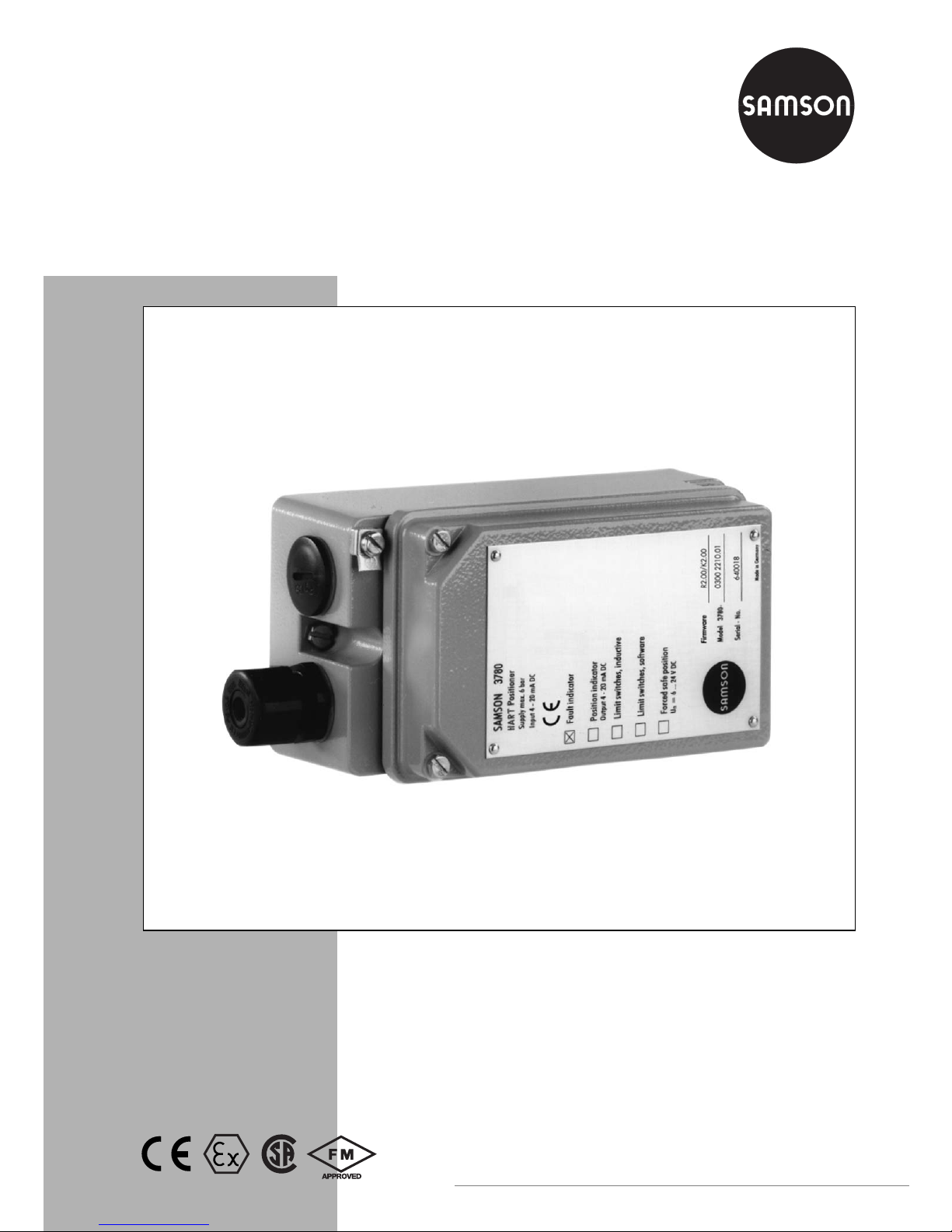
Type 3780
Mounting and
Operating Instructions
EB 8380-1 EN
Firmware R 2.22/K 2.23
Edition June 2004
Fig. 1 ⋅Type 378 0
Page 2

Contents Page
1. Design and principle of operation
. . . . . . . . . . . . . . . . . . . . . . 10
1.1 Options . . . . . . . . . . . . . . . . . . . . . . . . . . . . . . . . . . . 10
1.2 Communication . . . . . . . . . . . . . . . . . . . . . . . . . . . . . . . 11
2. Attachment to the control valve
. . . . . . . . . . . . . . . . . . . . . . . 13
2.1 Direct attachment to Type 3277 Actuator . . . . . . . . . . . . . . . . . . . 14
2.2 Attachment according to IEC 60534-6 . . . . . . . . . . . . . . . . . . . . 18
2.2.1 Mounting sequence . . . . . . . . . . . . . . . . . . . . . . . . . . . . . 18
2.2.2 Presetting the valve travel . . . . . . . . . . . . . . . . . . . . . . . . . . . 20
2.3 Attachment to rotary valves . . . . . . . . . . . . . . . . . . . . . . . . . . 22
2.3.1 Mounting the cam follower roll lever . . . . . . . . . . . . . . . . . . . . . 22
2.3.2 Mounting the intermediate piece . . . . . . . . . . . . . . . . . . . . . . . 22
2.3.3 Aligning and mounting the cam disk . . . . . . . . . . . . . . . . . . . . . 24
2.3.4 Reversing amplifiers for double-acting actuators . . . . . . . . . . . . . . . . 26
2.4 Fail-safe action of the actuator . . . . . . . . . . . . . . . . . . . . . . . . 26
3. Connections
. . . . . . . . . . . . . . . . . . . . . . . . . . . . . . . . . 28
3.1 Pneumatic connections . . . . . . . . . . . . . . . . . . . . . . . . . . . . 28
3.1.1 Pressure gauge . . . . . . . . . . . . . . . . . . . . . . . . . . . . . . . 28
3.1.2 Supply air pressure . . . . . . . . . . . . . . . . . . . . . . . . . . . . . 29
3.2 Electrical connections . . . . . . . . . . . . . . . . . . . . . . . . . . . . 29
3.2.1 Switching amplifiers . . . . . . . . . . . . . . . . . . . . . . . . . . . . . 31
3.2.2 Establishing communication . . . . . . . . . . . . . . . . . . . . . . . . . 32
4. Operation
. . . . . . . . . . . . . . . . . . . . . . . . . . . . . . . . . . 34
4.1 Write protection . . . . . . . . . . . . . . . . . . . . . . . . . . . . . . . 34
4.2 Activate/deactivate forced venting function . . . . . . . . . . . . . . . . . . 34
4.3 Default setting . . . . . . . . . . . . . . . . . . . . . . . . . . . . . . . . 35
4.3.1 Adjusting mechanical zero point . . . . . . . . . . . . . . . . . . . . . . . 35
4.3.2 Initialization . . . . . . . . . . . . . . . . . . . . . . . . . . . . . . . . . 35
4.4 Adjusting inductive limit switches . . . . . . . . . . . . . . . . . . . . . . . 37
5. Maintenance
. . . . . . . . . . . . . . . . . . . . . . . . . . . . . . . . 38
6. Servicing explosion-protected versions
. . . . . . . . . . . . . . . . . . . . 38
7. Summary of parameters
. . . . . . . . . . . . . . . . . . . . . . . . . . . 39
8. List of parameters
. . . . . . . . . . . . . . . . . . . . . . . . . . . . . . 42
9. Error messages and diagnostics
. . . . . . . . . . . . . . . . . . . . . . . 53
9.1 Information/alerts . . . . . . . . . . . . . . . . . . . . . . . . . . . . . . 54
9.2 Error messages . . . . . . . . . . . . . . . . . . . . . . . . . . . . . . . 56
Contents
2
EB 8380-1 EN
Page 3

9.3 Error messages during initialization without abortion . . . . . . . . . . . . 59
9.4 Error messages during initialization with abortion . . . . . . . . . . . . . . 60
Dimensional diagram
. . . . . . . . . . . . . . . . . . . . . . . . . . . 62
Type examination certificates
. . . . . . . . . . . . . . . . . . . . . . . 63
Safety instructions
Assembly, commissioning and operation of the device may only
be performed by trained and experienced personnel familiar
with this product. According to these mounting and operating instructions, trained personnel is referred to persons who are able
to judge the work they are assigned to and recognize possible
dangers due to their specialized training, their knowledge and
experience as well as their knowledge of the relevant standards.
Explosion-protected versions of this device may only be operated by personnel who have undergone special training or instructions or who are authorized to work on explosion-protected
devices in hazardous areas. See section 6 for more details.
For devices in type of protection EEx nA, the following applies:
live circuits may only be connected, interrupted, and switched
for installation, maintenance or repair purposes.
Devices that have already been used outside of hazardous areas
and are intended for use in hazardous areas in future shall comply with the safety demands placed on serviced devices. Prior to
operation, they shall be tested according to paragraph 26 "Repairing explosion-protected devices" of EN 50014:2000 to
meet the safety requirements specified in this standard.
Any hazards which could be caused by the process medium, the
signal pressure and moving parts of the control valve are to be
prevented by means of appropriate measures.
If inadmissible motions or forces are produced in the actuator as
a result of the level of the supply air pressure, this must be restricted by means of a suitable pressure reducing station.
Proper shipping and appropriate storage are assumed.
Note:
Devices with the CE mark meet the requirements specified in the
Directive 94/9/EC and the Directive 89/336/EEC.
The Declaration of Conformity is available on request.
EB 8380-1 EN
3
Page 4

Modifications of positioner firmware
Modifications of positioner firmware in comparison to previous version
Former New
For more details on the listed parameters, please also refer to the
list of parameters in section 8.
Positioner R 1.41 R 2.01
Parameters:
Operating direction Direction of action
The reference variable (w) is not assigned to the output signal
pressure (y) anymore, but to the travel/angle of rotation (x).
>> increasing/increasing, valve opens with increasing reference
variable.
<> increasing/decreasing, valve closes with increasing reference
variable.
Minimum transit time
filling/venting
Minimum transit time open/closed
The measured time is not referenced to filling/venting the
actuator, but to the opening and closing the valve.
Required transit time
filling/venting
Required transit time open/closed
The actuating time is not referenced to filling/venting the actuator,
but to the opening and closing the valve.
Cycle time factor
K_IS
Omitted
Initialization
For version
R2.02
or higher, an alarm message is generated for
deviations larger than 10 % when the type of initialization is
maximum range. It is for the user to decide if he wants to tolerate
the deviation.
Tolerated overshoot
If overshoot and dead band are exceeded by the negative
deviation value, the pulse is adapted.
Text field
Free space for storing information text in the field device.
4
EB 8380-1 EN
Page 5

Modifications of positioner firmware
Former New
Positioner 2.02 R 2.11
Parameters:
Minimum pulse
filling/venting
The minimum pulses for filling and venting are determined for
the travel ranges 0 to 20 %, 20 to 80 % and 80 to 100 %. The
minimum pulses are no longer determined during initialization.
Proportional-action
coefficient
KP_Y1 and KP_Y2
These factors are adapted to the actuator type selected and to
the transit times measured.
Gain factor
KD
Initialization
"Air leakage of pneumatic system" is displayed as alarm
message, but does not cause abortion of initialization anymore.
Upon initialization in the "nominal range", the positioner
assumes only 100 % travel (no overtravel).
"Wrong selection of rated travel/angle of rotation or
transmission" is displayed as alarm message, but does not cause
abortion of initialization anymore.
Positioner 2.11 R 2.21
Type of actuator
Change over type of actuator from "linear actuator" to "rotary
actuator"
Initialization type .................Based on maximum range
Transmission code................S90
Nominal angle.....................90°
End position when w <..........1 %
End position when w >..........99 %
Rot ation al an gle r ange star t ..0°
Rot ation al an gle r ange end ... 90°
Change over type of actuator from "rotary actuator" to "linear
actuator"
Attachment
.........................
Integral
...............................
Acc. to NAMUR
Initialization type .................Based on nominal range.......Based on nominal range
Mounting position................Arrow towards actuator........Arrow away from actuator
Transmission code................D1......................................
Pin position.......................... ........................................A
Rated travel .........................15 mm ................................15 mm
End position when w <..........1 %.....................................1 %
End position when w >..........125 %.................................125 %
Travel range start..................0 mm..................................0 mm
Travel range end ..................15 mm................................15 mm
Length of lever...................... ........................................42 mm
EB 8380-1 EN
5
Page 6

Modifications of positioner firmware
End position when w
</>
Changing the type of initialization from "maximum range" to
"nominal range" causes:
End position at < 1 % End position at > 125 %
Changing the type of initialization from "nominal range" to
"maximum range" causes:
End position at < 1 % End position at > 99 %
Extended
valve diagnostics
Supports TROVIS-EXPERT in version 1.0 or higher
Required transit time
open/closed
The adjustment range for the required transit times has been
limited to 75 s. Safe functioning can only be guaranteed up to
this limit value.
Initialization
During initialization, the minimum control pulses for the range
20 % to 80 % of the range of the manipulated variable are
determined and saved in the EEPROM.
Proportional-action
coefficient
KP_Y1 and KP_Y2
These factors are adapted to the type of actuator chosen and the
transit times measured.
Positioner 2.21
R 2.22
Correction in "manual" operating mode and direction of action
Correction in zero calibration started via communication
Communication K 1.00 K 2.01
Characteristic type
Free space for entering information on the description of the
user-defined characteristic saved in the device. Can be stored in
the field device.
For version K 2.02 or higher, when selecting [equal percentage]
or [equal percentage reverse], the description text in parameter
characteristic type of the device is automatically set to the
selection made.
Communication K 2.02 K 2.11
Supports all functions of R 2.11
Type of initialization
For K 2.11 or higher, the default value is "maximum range"
End position when w >
For K 2.11 or higher, the default value is 99 %
6
EB 8380-1 EN
Page 7

Positioner versions
Former New
Communication
K 2.13 K 2.21
Supports all functions of R 2.21 as well as TROVIS-EXPERT in
version 1.0 or higher
Communication
K 2.21
K 2.22
Supports all functions of R 2.21 as well as TROVIS-VIEWin
version 2.0 or higher
New for model index
3780-
x...x. 01 or higher:
Write protection switch
If this option is activated using the switch, the positioner settings cannot be written over by
HART
®
communication. See section 4.1 for more details on the write protection switch.
Model index
3780-
x...x. 03 or higher are suitable for the extended valve diagnosis using
the TROVIS-EXPERT software.
Positioner versions
Model
3780 -
XXXXX
Explosion
protection
Without
Ex II 2 G EEx iA IIC T6 as per ATEX
CSA/FM
Ex II 3 G EEx nA II T6 as per ATEX
0
1
3
8
Additional
accessories
Limit switches Without
2 inductive
2 software
0
2
3
Forced venting Without
With
0
1
Position transmitter Without
4...20 mA
0
1
Pneumatic
connections
NPT 1/4-18
ISO 228/1-G 1/4
1
2
EB 8380-1 EN
7
Page 8
Positioner
Rated travel, adjustable Direct attachm. 5 to 30mm
Attachment acc. to IEC 60534-6 (NAMUR), 5 to 255 mm or 30 to 120° C
Reference variable Two-wire connection, signal range 4 to 20 mA, span 4 to 16 mA
Min. cu rrent = 3 .6 mA , load ≤10.8 V (corresponding to 540 Ω at 20 mA),
static destruction limit 500 mA
Supply Supply air from 1.4 to 6 bar (20 to 90 psi)
Sign al pres su re (out pu t) 0 ba r t o p ressu re of supp ly ai r
Characteristic, adjustable Linear, equal percentage, reverse equal percentage, user-programmable
Deviation from characteristic ≤1 %
Dea d ban d Adj ustable f rom 0. 1 to 10 %, d efault 0.5 %
Resolution
≤
0.05 %
Transit time to travel Up to 75 s, separately adjustable for exhaust and supply air
Moving direction Reversible, adjustment via software
Air consumption Independent of supply air <90l
/h
Air delivery Actuator filled: for Δp = 6 bar 9.3 m
/h, for Δp = 1.4 bar 3.5 m
/h
Actuator vented: for Δp = 6 bar 15.5 m
/h, for Δp = 1.4 bar 5.8 m
/h
Perm. ambient temperature− 20 to 80 °C, with metal cable gland − 40 to 80 °C
Devices with position transmitter only − 20 to 80 °C
For explosion-protected devices, see type examination certificate in appendix
Effects Temperature: ≤0.15 %/10 K, supply: none, vibrations: none up to 250 Hz and 4 g
Explosion protection EEx ia IIC T6, see type examination certificate
Degree of protection IP 65 by using the filter check valve included
Electromagnetic
compatibility
Requirements stipulated in EN 61000-6-2, EN 61000-6-3 as well as NAMUR
Recommendation 21 have been met
Electrical connections 1 cable gland M20x1.5, black plastic;
other threaded hole M20x1.5 available
Fault alarm output For connection to switching amplifier acc. to EN 60947-4-6, static destruction limit 16 V
Forced venting
(model index .03 or
higher)
Activated/deactivated by a switch inside case
Input: 6...24 V DC, R
appr ox . 6 kΩ, at 24 V D C ( de pendin g o n volta ge ), swit ch ing poi nt
for "1" signal at ≥ 3 V, si gnal "0 " o nl y at 0 V, K
val ue 0.17; st at ic dest ru ction l im it 45 V
Technical data
8
EB 8380-1 EN
Page 9

Communication
Hardware requirements SAMSONs TROVIS-VIEW Operator Interface (see Data Sheet T 6661 EN) or handheld
communicator, e.g. Type 275 by Rosemount
Integration of other operator interfaces, e.g. DTM, are available
Data transmission HART
®
Fiel d C om munica ti on Prot oc ol
Impedance in HART
®
frequency range: receive: 350 to 450 Ω; send: approx. 115
Ω
Accessory equipment
Inductive limit switches Two Type SJ 2 SN Prox. Switches for connection to switching amplifier acc. to EN 60947-5-6
Software limit switches Two configurable limit values for connection to switching amplifier acc. to EN 60947-5-6
Switching hysteresis 1%, static destruction limit 16 V
Analog position
transmitter
Two-wire transmitter, output 4 to 20 mA
Sup pl y: termin al vo ltage 12 to 35 V D C, stat ic de struct io n limit 40 V
Direction of action reversible, characteristic linear, operating range: 10 % to + 114 %
DC current signal ripple content: 0.6 % at 28 Hz/IEC 381 T1
Resolution ≤0.05 %
HF influence <2 % with f= 50 to 80 Mhz
Infl ue nce au x. su pply: n on e; temp er ature i nf luence : s ame as p os itione r
Materials
(num be rs acc or di ng to DIN )
Case Di e- cast al um inum, c hr om ed and pl astic- co at ed
External parts: stainless steel 1.4571 and 1.4301
Weight Approx. 1.3 kg
Versions
EB 8380-1 EN
9
Page 10

1. Design and principle of operation
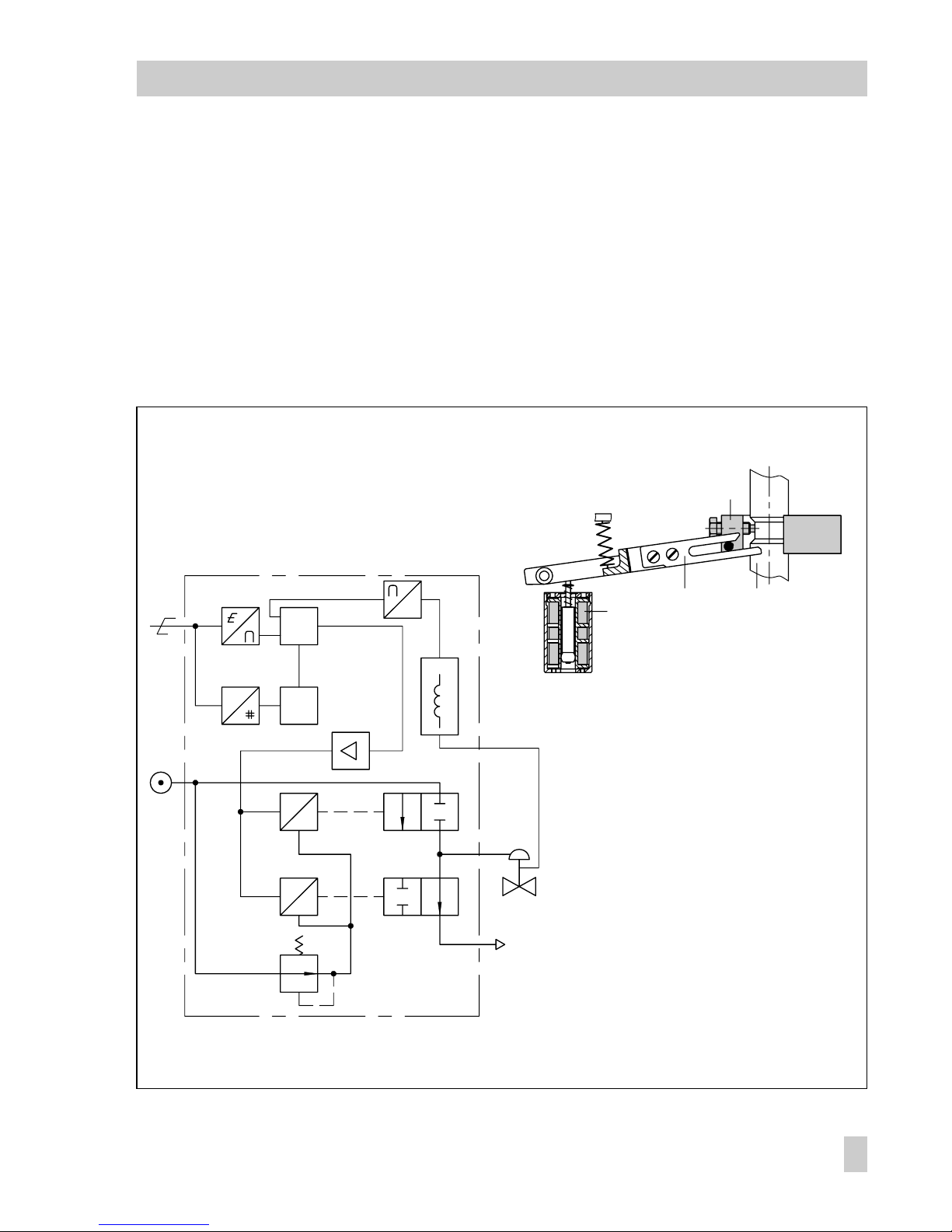
The positioner essentially consists of an inductive, non-contact travel measuring system and an electrically controlled valve
block comprising two 2/2-way on-off
valves and an electronic unit. This unit contains two microcontrollers for processing the
control algorithm and managing the communication.
Whenever a deviation between the actual
valve travel (actual value) and the reference
variable (set point) occurs, the microcontroller produces binary pulse-pause modulated
signals to control the two 2/2-way on-off
valves, each of which is assigned an amplifier. One of these valves controls the exhaust air, and the other one controls the supply air.
The supply air valve (3) switches the supply
air (7, supply air pressure 1.4 to 6 bar) to
the actuator (filling). The exhaust air valve
(4) controls the air exhausted from the actuator to the atmosphere (venting). These onoff valves can either have the switching
states - permanently open, permanently
closed - or generate single pulses of changing widths. With the two valves being controlled, the plug stem moves to a position
corresponding to the reference variable. If
there is no system deviation, both the supply
air and the exhaust air valve are closed.
As a standard feature, the positioner is
equipped with a fault alarm output (binary
output according to EN 60947-5-6) used to
signalize a fault to the control room.
Activating the write protection switch located in the hinged cover prevents the positioner settings from being overwritten by the
HART
®
protocol.
Forced venting function
The positioner is controlled via a 6 to
24 V signal, causing the signal pressure
to be applied to the actuator. If this voltage signal decreases, the signal pressure is
shut off and the actuator is vented. The
springs contained in the actuator move the
valve to its fail-safe position.
The forced venting function is installed in all
positioners from model index .03 or higher.
The function can be activated or deactivated by a switch. See section 4.2 (page
34) for more details.
1.1 Options
As a supplement to the standard positioner
version, there are several additional options
to extend the positioner functions.
Limit switches
To signalize the valves end positions in failsafe circuits, either two software limit switches or two proximity switches can be used.
Position transmitter
The position transmitter is an intrinsically
safe 2-wire transmitter controlled by the
microcontroller of the positioner. It serves to
assign the valve position with the 4 to 20
mA output signal. The position transmitter
signalizes both end positions, "valve closed"
or "valve fully open", as well as all intermediate positions. Since the valve positions
are signalized to the positioner independently of the input signal (minimum
current must be observed), the position
transmitter is a suitable option for checking
the current valve position.
10
EB 8380-1 EN
Design and principle of operation
Page 11
1.2 Communication
For communication, the positioner is
equipped with an interface for the HART
®
protocol (Highway Addressable Remote
Transducer). Data transmission is accomplished by superimposing an FSK signal
(FSK = Frequency Shift Keying) over the
existing 4 to 20 mA signal lines for the reference variable.
You can configure and operate the positioner either via HART
®
-compatible, handheld communicator or via PC, using an FSK
modem and an RS-232 interface.
After mechanically resetting the positioner
to zero, it can be automatically started up
via initialization procedure. During this initialization procedure, zero is automatically
adjusted, and the preset span is checked.
Fig. 2 ⋅Functional diagram
11 10
1
12
e
p
3
4
2
5
1
G
μC
FSK
e
p
G
μC
6
7
8
1 Inductive displacement sensor
2 Microcontroller
3 2/2 way valve for supply air
4 2/2 way valve for exhaust air
5 Microcontroller
6 Pressure regulator
7 Supply air 1.4 to 6 bar
8 Reference variable 4 to 20 mA
with superimposed FSK signal
10 Actuator stem
11 Lever
12 Clamp
EB 8380-1 EN
11
Design and principle of operation
Page 12

The positioner is supplied with a standard
configuration applying to a valve with
15 mm rated travel, which is designed for
integrated positioner attachment.
An individual configuration needed to
adapt the positioner to deviating actuators
can only be carried out by means of a communicator or a PC with a connected FSK
modem, using the HART
®
protocol.
You can enter the following parameters:
control characteristic, direction of action,
limitation of travel, travel range, transit time
to travel and fault messages.
Operating software
TROVIS-VIEW
for devices with firmware K 2.11 or
higher, Data Sheet T 6661 EN
IBIS
(DOS-based, no longer runs on
Windows 2000/ME/XP/NT),
see EB 8380-2 EN for more details
DMT 1.2 and PACTware
Integration
e.g. Fisher AMS, Siemens PDM, etc.
Handheld communicator
DD-based handheld communicators,
e.g. Fisher-Rosemount HART
®
Communica-
tor.
12
EB 8380-1 EN
Design and principle of operation
Page 13

2. Attachment to the control valve
The positioner can be attached either directly to a SAMSON Type 3277 Actuator,
or according to Namur (IEC 60534-6), to
control valves with cast yokes or rod-type
yokes.
In combination with an intermediate piece,
the device can also be attached as rotary
positioner to rotary actuators.
Since the standard positioner unit is delivered without accessories, the required
mounting parts and their order numbers
have to be derived from the tables.
Note!
For quick-acting control valves with a small
travel volume (transit time < 0.6 s), it might
be necessary to replace the filter installed in
the output pressure bore with a screw-in
throttle to obtain good control properties.
For further information, refer to sections
2.1, 2.2 and 2.3.
Caution!
The positioner does not have a venting
plug. Instead the air is exhausted via venting plugs on the mounting parts (see also
Fig. 3, 5 and 7).
A filter check valve for the exhaust air is supplied with every positioner (located underneath a transparent cover at the back of the
positioner). Use this filter check valve in
place of the standard venting plug included
in the accessories. The IP 65 degree of protection to prevent dirt and moisture entering
the device is only achieved when this filter
check valve is used.
EB 8380-1 EN
13
Attachment to the control valve
Page 14

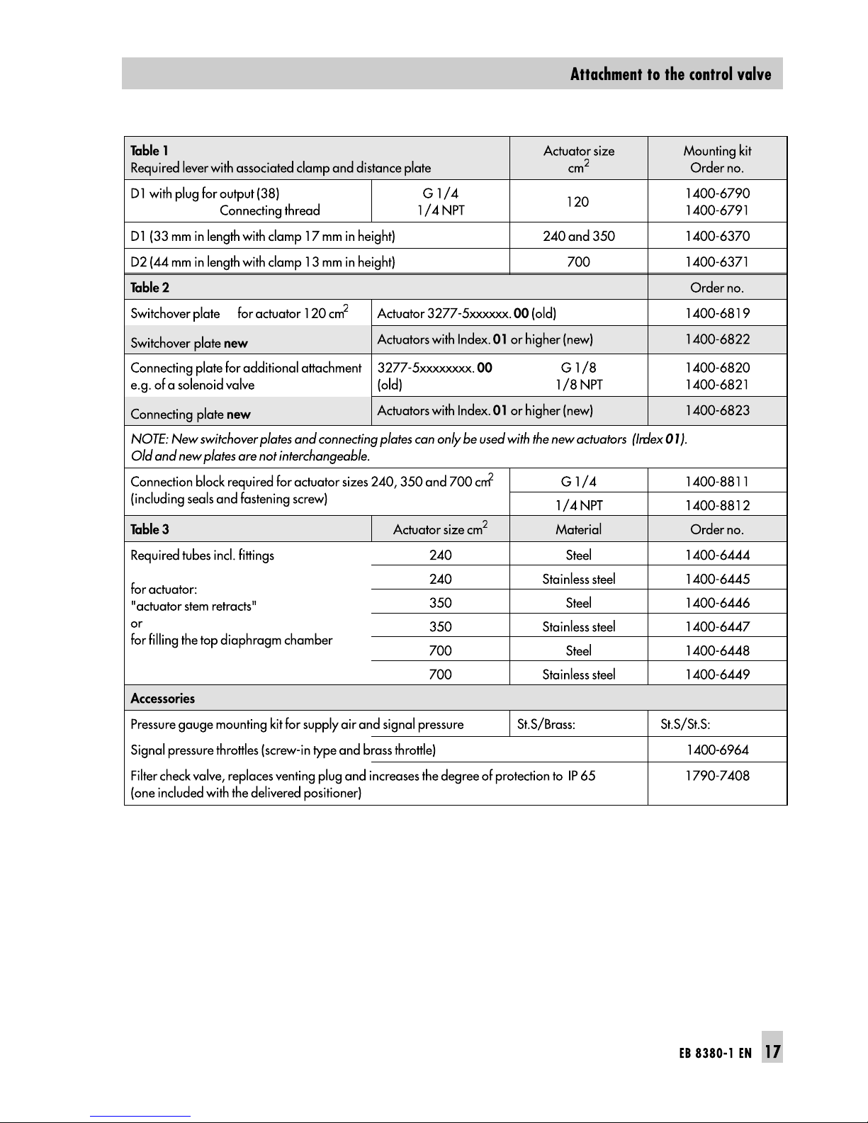
2.1 Direct attachment to Type 3277
Actuator
For the selection of the required mounting
parts, refer to Tables 1, 2 and 3 (page 17).
When looking at the signal pressure connection or the switchover plate (Fig. 3) from the
top, the positioner must be attached to the
left side of the actuator. The
arrow
on the
black case cover (Fig. 12) should then point
towards
the
diaphragm chamber.
Exception:
Control valves in which the plug
closes the seat area when the actuator stem
retracts. In this case, the positioner has to
be attached to the right side of the yoke, i.e.
with the arrow pointing away from the diaphragm chamber).
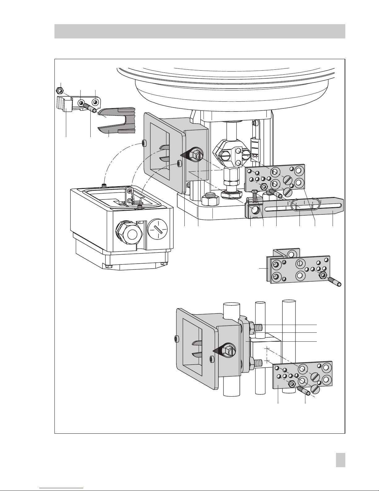
1. First screw the clamp (1.2) to the actua-
tor stem. Make sure the fastening screw
is located in the groove of the actuator
stem.
2. Screw the associated lever D1 or D2 to
the transmission lever of the positioner.
3. Fasten distance plate (15) with seal to-
wards the actuator yoke.
4. Place positioner on the plate (15) so
that the lever D1 or D2 will slide centrically over the pin of the clamp (1.2).
Then screw on to distance plate (15).
5. Attach cover (16).
Note!
For quick-acting control valves (transit time
< 0.6 s), it is necessary to replace the filter
installed in the output pressure bore (Output
38) with a screw-in throttle (accessories specified in Table 3).
Actuator with 240, 350 and 700 cm
2
6. Check whether the tongue of the
seal (17) is aligned on the side of the
connection block such that the actuator
symbols for "Actuator stem extends" or
"Actuator stem retracts" match the actuator design.
Otherwise, remove the three fixing
screws, remove the cover plate (18) and
reinsert the seal (17) turned by 180°.
When using an
old
connection block,
turn the switch plate (19) such that the
corresponding actuator symbol is
aligned with the arrow.
7. Place connection block with the associated sealing rings against the positioner
and the actuator yoke and screw it
tight, using the fastening screw.
For actuators with fail-safe action "actuator stem retracts", additionally install
the ready-made signal pressure pipe
between the connection block and the
actuator.
Actuator with 120 cm
2
With Type 3277-5 Actuator with 120 cm
2
the signal pressure is transmitted via the
switchover plate to the diaphragm chamber.
For a rated travel of 7.5 mm, a brass
throttle has to be pressed into the seal located in the signal pressure input on the actuator yoke. With 15 mm rated travel, this
is only required when the supply air pressure is higher than 4 bar.
6. Remove the vent plug on the back of the
positioner and close the side-located
signal pressure output (38) with the
plug from the accessory kit.
14
EB 8380-1 EN
Attachment to the control valve
Page 15
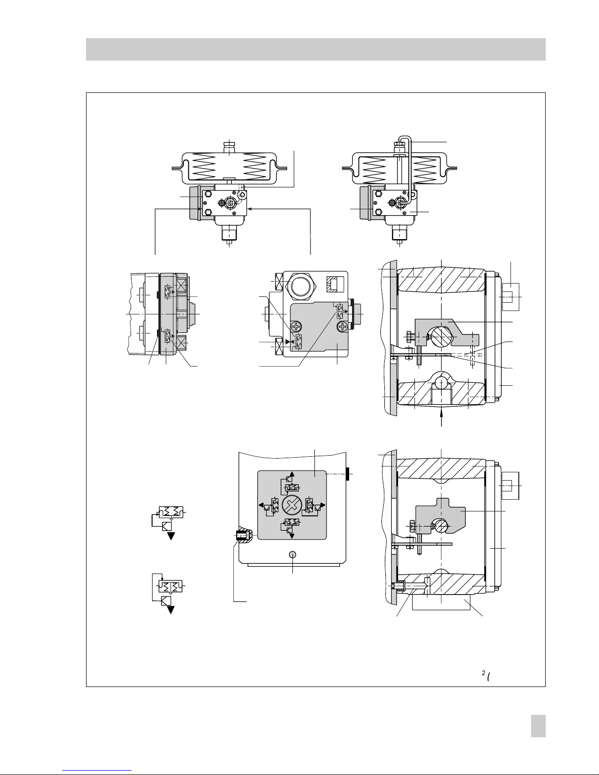
Actuator stem
retracts
Ventin g
"Actuator stem
retracts" symbol
With switch plate (formerly)
With seal
(new)
SUPPLY
1817 19
1.2
D2
D1
17
16
15
1.2
16
17
15
Actuator stem retracts
Internal signal pressure connection
Signal pressure
connection via piping
1.2 Clamp
D 1 Lever
D2 Lever
15 Distance plate
16 Cover
17 Seal
18 Cover plate
19 Switch plate
Signal pressure hole
Side view of connection block
Connection block
Mark
Mark
"Actuator stem
extends" symbol
Switchover plate
Switchover plate
Signal pressure input
Signal pressure
input, if necessary
with brass throttle
Actuator stem extends
Actuator stem
extends
Fig. 3 ⋅Attachment and signal pressure connection for Type 3277 (top) and Type 3277-5 with 120 cm (below)
EB 8380-1 EN
15
Attachment to the control valve
Page 16

7. Mount the positioner so that the hole in
the distance plate (15) matches the seal
located in the hole of the actuator yoke.
8. Align the switchover plate with the
corresponding symbol for left attachment according to the marking and
screw tight onto the actuator yoke.
Important!
If, with the 120 cm
2
actuator in addition to
the positioner, a solenoid valve or a similar
device is attached to the actuator, do not
remove the rear M3 screw. In this case, the
signal pressure has to be fed from the signal pressure output to the actuator via the
required connecting plate (see Table 2). The
switchover plate is not used.
Note!
For quick-acting control valves (transit time
< 0.6 s), it is necessary to replace the filter
installed in the output pressure bore (Output
38) with a screw-in throttle (accessories specified in Table 3).
Filling the spring chamber with air
If the spring chamber of the Type 3277 Actuator must be filled with the air exhausted
from the positioner, the spring chamber (version "Actuator stem extends") can be connected to the connection block by means of
a tube (see Table 3). To proceed, remove
the venting plug in the connection block.
In Type 3277-5 when "Actuator stem retracts" the exhausted air from the positioner
is constantly applied to the spring chamber
through an internal hole.
16
EB 8380-1 EN
Attachment to the control valve
Page 17
1)
Order with every pressure gauge kit: 2 restrictions (1790-6121)
1)
1402-0938 1402-0939
Page 18

2.2 Attachment according to
IEC 60534-6
For the selection of the required mounting
parts, refer to Tables 4 and 5 (page 21).
The positioner is attached according to
NAMUR using an adapter housing as
shown in Fig. 4. The valve travel is transmitted via the lever (18) and the shaft (25)
to the bracket (28) of the adapter housing
and then to the pin (27a) located at the positioner lever.
To attach the positioner, the mounting parts
listed in Table 4 are required. Which lever
is to be used depends on the rated valve
travel.
Once the positioner is attached, however,
the
arrow
on the black case cover has to
point downwards
away
from the
dia-
phragm actuator
. (
Exception
: Control
valves in which the plug closes the seat area
when the actuator stem retracts. In this case,
the arrow has to point
towards
the dia-
phragm actuator).
Note!
For quick-acting control valves (transit time
< 0.6 s), it is necessary to replace the filter
installed in the output pressure bore (Output
38) with a screw-in throttle (accessories specified in Table 4).
2.2.1 Mounting sequence
NOTE
Before you mount the parts, load the actuator with air pressure so that the valve is set
to 50 % of its travel. This will ensure the
exact alignment of the lever (18) and the
bracket (28).
Control valve with cast yoke
1. Use countersunk screws to screw the
plate (20) to the coupling which connects the plug and actuator stem. With
2100 and 2800 cm
2
actuators, use ad-
ditional mounting bracket (32).
2. Remove rubber plug from the adapter
housing and fasten the housing to the
NAMUR rib, using the hexagon head
screw.
Control valve with rod-type yoke
1. Screw plate (20) to the follower clamp
of the plug stem.
2. Screw studs (29) into the adapter housing.
3. Place the housing with the plate (30) on
either the right or left side of the valve
rod and screw the housing tight by
using nuts (31). While doing so, make
sure that lever (18) to be mounted subsequently is horizontal (when the valve
is at midtravel).
4. Screw the pin in a hole in the center
row of holes in the plate (20) and lock it
such that it will be located above the
correct lever marking (1 to 2) for the assigned travel, see Table 5. Intermediate
values must be calculated. Beforehand,
18
EB 8380-1 EN
Attachment to the control valve
Page 19
2
1,5
1
2826
AB
24 25 22
32
31
20 19
19 21 2023 18
27b
27a
29
30
Mounting position
Fig. 4 ⋅Attachment according to IEC 60534-6 (NAMUR)
18 Lever N1, N2
19 Pin
20 Plate
21 Clamp
22 Clamping plate
23 Screw
24 Pointer
25 Shaft
26 Lever of positioner
27a Coupling pin
27b Lock nut
28 Bracket
29 Studs
30 Plate
31 Nuts
32 Mounting bracket
Attachment to
NAMUR rib
Attachment to rod-type yoke
EB 8380-1 EN
19
Attachment to the control valve
Page 20

move the clamp (21) to surround the
pin.
5. Measure the distance between the center of the shaft (25) and the center of
the pin (19). You will be prompted for
this value subsequently during the configuration of the positioner.
2.2.2 Presetting the valve travel
1. Adjust the shaft (25) in the adapter
housing so that the black pointer (24) is
aligned with the casted marking on the
adapter housing.
2. Screw tight clamping plate (22) in this
position, using a screw (23).
3. Screw in the pin (27) at the positioner
lever (26) and secure it with a hex nut
on the opposite side. Note the mounting position A or B respectively according to Table 5 and Fig. 5.
4. Put the positioner to the adapter housing such that the pin (27) will lie
properly within the arms of the bracket
(28).
To do so, insert a 2.5 mm Allen key or
a screwdriver from the front into the
hole located below the oblong hole on
the cover plate, and push the positioner
lever in the required position.
5. Screw the positioner to the adapter
housing.
6. Relieve the actuator from the signal
pressure.
20
EB 8380-1 EN
Attachment to the control valve
Page 21

Ta bl e 4
Attachment acc. to IEC 60534-6 Control valve Travel in mm With lever Order no.
NAMUR mounting kit
Parts illustrated in Fig.4
Valve with cast yoke
7.5 to 60 N1 (125 mm) 1400-6787
30 to 120 N2 (212 mm) 1400-6789
Valve with
rod-type yoke
with
rod diameter
in mm
20 to 25 N1 1400-6436
20 to 25 N2 1400-6437
25 to 30 N1 1400-6438
25 to 30 N2 1400-6439
30 to 35 N1 1400-6440
30 to 35 N2 1400-6441
Attac hm ent to F is he r and M as on eilan l inear a ct uators (o ne each of bo th mo unting ki ts is needed per one
actuator)
1400-6771
and
1400-6787
Accessories
Order no.
Pre ss ure gau ge mo unting bl ock G 1/4
1/4 N PT
1400-7458
1400-7459
Pre ss ure gau ge set St. s t. /Brass
St. st./St. st.
1400-6957
1400-6958
Signal pressure throttles (screw-in type and brass throttle) 1400-6964
Filter check valve, replaces venting plug and increases the degree of protection to IP 65
(one in cluded wi th the d el ivere d p os itione r)
1790-7408
Table 5
Attachment according to IEC 60534-6
Travel in mm *) 7.51515303060306060120
Pin on marking *) 1 12121212
Corresp. distance pin/lever fulcrum 42 428442848416884168
With lever N1 (125 mm in length) N2 (212 mm in length)
Transmission pin (27) on position A A B A B
*) Deviating travel values (intermediate values) must be calculated accordingly.
EB 8380-1 EN
21
Attachment to the control valve
Page 22

2.3 Attachment to rotary actuators
For the selection of the required mounting
parts, refer to Table 6 (page 25).
The positioner can also be attached to rotary actuators in accordance with VDI/VDE
3845 by using the mounting parts and accessories listed in Table 6. In this arrangement, the actuators rotary motion is converted via the cam disk on the actuator shaft
and the feeler roll of the positioner lever to
a linear motion required by the positioners
inductive displacement sensor system.
Each cam disk is suitable for two characteristics, i.e. for the ranges of angle of rotation from 0 to 90° (recommended for
angles below 90°) and 0 to 120° (recommended for 90° and greater).
For double-acting, springless rotary actuators, it is necessary that a reversing amplifier be attached to the positioner on the side
of the connection. (See section 2.3.4.)
If the positioner is attached to a SAMSON
Type 3278 Rotary Actuator, the air exhausted from the positioner is admitted to
the inside of the actuator and the chamber
behind the diaphragm. No additional piping is required.
If the positioner is attached to actuators of
other manufacturers (NAMUR) the air is applied to the chamber behind the diaphragm
through a tube assembly and a tee, connected between actuator and intermediate
piece.
Note!
For quick-acting control valves (transit time
< 0.6 s), it is necessary to replace the filter
installed in the output pressure bore (Output
38) with a screw-in throttle (accessories spe-
cified in Table 6).
2.3.1 Mounting the cam follower
roll lever
1. Place lever with the attached roll (35)
on the side of the transmission lever
(37) and secure it with the enclosed
screws (38) and washers.
2.3.2 Mounting the intermediate
piece
SAMSON Type 3278 Actuator:
1. Screw adapter (36) to the free end of the
rotary actuator shaft with two screws.
2. Place the intermediate piece (34) on the
actuator case and fasten with two
screws. Align intermediate piece of the
positioner so that the air connections of
the positioner will face towards the diaphragm case side.
Actuators according to VDI/VDE 3845
1. Place the complete intermediate piece
(34, 44, 45 and 42) onto the mounting
bracket included in the delivery (fixing
level 1 VDI/VDE 3845) and screw tight.
2. Align the cam disk (40) and scale (39) as
described in section 2.3.3 and fasten tight.
With springless actuators, the reversing amplifier must be screwed to the side of the positioner case. See section 2.3.4 for more details.
22
EB 8380-1 EN
Attachment to the control valve
Page 23

Fig. 5 ⋅Attachment to rotary actuators
33
3835
39
39
40
34
36
40
34
44
45
42
43
37
Attachment to SAMSON Type 3278
Attachment acc. to
VDI/VDE 3845
Vent plug or filter
check valve
33 Positioner
34 Intermediate piece
35 Lever w. cam follower roll
36 Adapter
37 Transmission lever
38 Screws
39 Scale
40 Cam disk
41 Actuator shaft
42 Plate
43 Bracket
44 Coupling
45 Seal
EB 8380-1 EN
23
Attachment to the control valve
Page 24

2.3.3 Aligning and mounting of
the cam disk
In rotary actuators with spring-return mechanism, the built-in actuator springs determine the fail-safe position and the direction
of rotation of the control valve (either
counterclockwise or clockwise).
With double acting, springless rotary actuators, the direction of rotation depends on
both the actuator and the valve model used.
Any adjustments are only permitted when
the valve has been closed.
The direction of action of the positioner, i.e.
whether the valve shall either open or close
when the reference variable increases, has
to be software-adjusted via the communication (increasing/increasing or increasing/decreasing direction of action).
1. Position the cam disk with the scale on
the adapter (36) or the coupling (44)
and fasten the screw loosely at first.
The cam disk carries two cam sections. The
starting point of each section is marked by
a small bore.
Note!
With the valve closed, the starting point
(bore hole) of the respective characteristic is
to be aligned so that the center of rotation
of the cam disk, the 0° position on the
scale, and the arrow mark on the disk are
aligned.
The starting point when the valve is closed
should not under any circumstances be
below the 0° position!
With actuators with fail-safe position "Valve
OPEN", the maximum signal pressure must
be applied to the actuator before aligning
the cam disk.
With springless actuators, the supply air
must be connected.
2. In aligning the cam disk, clip on the
double-sided scaled disk in such a way
that the valve on the scale will correspond to the direction of rotation of the
control valve. Only then, secure the
cam disk with the fastening screws.
Securing the aligned cam disk
If the cam disk should be additionally secured to prevent it from being turned, proceed as follows:
Choose one of the four bore holes located
centrically around the center bore on the
cam disk which is suitable to secure the cam
disk.
Drill a hole in the adapter (36) or coupling
(44) through the selected hole so that a
2 mm dowel pin can be inserted in this hole.
3. Attach the positioner to the intermediate
piece (34) so that the lever (35) contacts
the cam disk with its cam follower roll.
To do so, insert a 2.5 mm hexagon
socket key or a screw driver from the
front into the bore hole which can be
seen below an oblong hole on the cover
plate and bring the positioner lever in
the required position.
4. Screw the positioner onto the intermediate piece.
24
EB 8380-1 EN
Attachment to the control valve
Page 25

Fig. 6 ⋅Aligning the cam disk
Ta b le 6
Rotary actuators (Complete mounting parts, but without cam disks)
SAMSON Type 3278 Actuator Attachmt. acc. to VDI/VDE 3845 Attachment to Masoneilan actuator
Actuator
160 cm
Actuator
320 cm2
Camflex I
DN 25 ...100
Camflex I
DN 125...250
Camflex II
Order no.
1400-7103 1400-7104 1400-8815 1400-7118 1400-7119 1400-7120
Pip in g kit 8 x 1 st ai nl. st ee l
G 1400-6670 1400-6672
NPT 1400-6669 1400-6671
Accessories
Order no.
Reversing amplifier for double-acting, springless actuators G: 1079-1118 NPT: 1079-1119
Cam disk (0050-0089) with accessories, angle of rotation 0 to 90° and 0 to 120° 1400-6959
Cam disk (0050-0089) especially for VETEC, adjustable to 0 to 75° via software 1400-6960
Cam disk (0050-0090) especially for Camflex, adjustable to 0 to 50° via software 1400-6961
Pressure gauge mounting block G 1/4: 1400-7458 1/4 NPT: 1400-7459
Pressure gauge set St. st./Br.: 1400-6957 St. st./St. st.: 1400-6958
Signal pressure throttles (screw-in type and brass throttle) 1400-6964
Filt er check v alve, r ep laces v enting pl ug and i nc rease s t he degre e o f p ro tectio n t o I P 6 5
(one included with the delivered positioner)
1790-7408
Cam follower roll
Starting point
Holes to secure
cam disk
Insert clip and then press
tongues outwards!
Control valve opens
counterclockwise
View onto actuator shaft from positioner
Control valve opens
clockwise
EB 8380-1 EN
25
Attachment to the control valve
Page 26

2.3.4 Reversing amplifier for
double-acting actuators
For the use with double-acting actuators,
the positioner must be fitted with a reversing
amplifier.
The reversing amplifier is listed as an accessory in the Table 6 on page 25.
The output signal pressure of the positioner
is supplied at the output A
1
of the reversing
amplifier. An opposing pressure, which
equals the required supply pressure when
added to the pressure at A
1,
is applied at
output A
2
. The rule A1 + A2 = Z applies.
Mounting
Note!
Prior to attaching the reversing amplifier,
remove the sealing plug (1.5). The rubber
seal (1.4) must remain installed.
1. Screw the special nuts (1.3) from the ac-
cessories of the reversing amplifier into
the threaded connections of the positioner.
2. Insert the gasket (1.2) into the recess of
the reversing amplifier and push both
the hollowed special screws (1.1) into
the connecting boreholes A1 and Z.
3. Place the reversing amplifier onto the
positioner and screw tight using both
the special screws (1.1).
4. Screw the enclosed filter (1.6) into the
connecting boreholes A1 and Z using a
screwdriver (8 mm wide).
Signal pressure connections
A
1
: Output A1 leading to the signal pressure connection at the actuator which opens
the valve when the pressure increases
A
2
: Output A2 leading to the signal pressure connection at the actuator which closes
the valve when the pressure increases
Enter the actuator as "Double-acting
without spring-return mechanism" in
the user interface under Start-up → Actuator type.
2.4 Fail-safe action of the actuator
Note!
If the fail-safe action of the actuator is
changed subsequently by modifying the actuator springs from "Actuator stem extends"
to "Actuator stem retracts", the mechanical
zero must be readjusted and the positioner
must be re-initialized.
26
EB 8380-1 EN
Reversing amplifier for double-acting actuators
Page 27

1.3 1.2 1.1 1
Output 38 Supply 9
A
1
1.5 1.6
Z
A
2
1.4
A
1
A
2
Output 38 Supply 9
1.3 1.21.1
1.6
Z
A
1
Fig. 7 ⋅Mounting a reversing amplifier
Control signals
to the actuator
1 Reversing amplifier
1.1 Special screws
1.2 Gasket
1.3 Special nuts
1.4 Rubber seal
1.5 Plug
1.6 Filter
From the positioner
EB 8380-1 EN
27
Reversing amplifier for double-acting actuators
Page 28

3. Connections
3.1 Pneumatic connections
The air connections are either 1/4 NPT or
G 1/4 tapped holes. The customary fittings
for metal and copper tubes or plastic hoses
can be used.
Note!
The supply air has to be dry and free from
oil and dust. The maintenance instructions
for upstream pressure reducing stations
must be observed. Carefully blow through
all air tubes and hoses before connecting
them.
If the positioner is attached directly to the
Type 3277 Actuator, the connection of the
positioners output pressure to the actuator
is fixed. For Namur attachment, the signal
pressure can be applied to either the upper
or lower diaphragm chamber of the actuator, depending on the actuators fail-safe position.
Exhaust air:
The exhaust air connection of
the positioner is located in the mounting kit.
If the positioner is attached directly, a vent
plug is located in the plastic cover of the actuator. For Namur attachment, it is in the
adapter housing and for attachment to rotary actuators, it will either be located in
the intermediate piece or in the reversing
amplifier.
3.1.1 Pressure gauge
To monitor the positioner operation, we recommend connecting a pressure gauge for
supply air and signal pressure. These parts
are listed as accessories in Table 3, 4 or 6.
Nut Throttle with filter
(1790-6121)
Fig. 8 ⋅Attaching the pressure gauge
2...3mm
28
EB 8380-1 EN
Connections
Page 29

3.1.2 Supply air pressure
The required supply air pressure depends
on the bench range and the actuators failsafe action. The bench range is registered
on the nameplate either as spring range or
signal pressure range.
Actuator stem extends:
required supply air pressure =
upper bench range value + 0.2 bar
at least 1.4 bar.
Actuator stem retracts:
for tight-closing valves, the signal pressure
p
st max
is roughly estimated as follows:
pst
max
= F +
d
2
⋅ π ⋅ Δp
4 ⋅ A
[bar]
d = Seat diameter [cm]
Δ
p = Differential pressure p
p [bar]
A = Actuator area [cm
]
F = Upper bench range value of the actuator [bar]
If there are no specifications, calculate as
follows:
required supply air pressure =
upper bench range value + 1 bar
3.2 Electrical connections
As far as the electrical installation of
the device is concerned, the relevant
national regulations governing the
installation of electrical equipment
and the national accident prevention
regulations of the country of destination must be adhered to.
In Germany, these are the VDE regulations and accident prevention regulations of the employers liability insurance.
For installation in hazardous areas,
the following standards apply: EN
60079-14: 1997; VDE 0165 Part
1/8.98 "Electrical apparatus for explosive gas areas" and EN 50281-12: VDE 0165 Part 2/11.99 "Electrical apparatus for use in the
presence of combustible dust".
For intrinsically safe electrical apparatus that are certified according
to the Directive 79/196/EEC, the
data specified in the certificate of
conformity apply for connection of
intrinsically safe circuits.
For intrinsically safe electrical apparatus that are certified according
to the Directive 94/9/EC, the data
specified in the EC type examination
certificate apply for connection of intrinsically safe circuits.
Note:
It is absolutely necessary to
keep to the terminal plan specified
in the certificate. Reversal of the electrical connections may cause the explosion protection to be ineffective!
EB 8380-1 EN
29
Connections
Page 30

Note on the selection of cables and wires:
To run several intrinsically safe circuits in a
multi-core cable, read paragraph 12 of
EN 60039-14; VDE 0165/8.98.
For generally used insulating materials, for
example polyethylene, the radial thickness
of the conductor insulation has to be at least
0.2 mm. The diameter of a single wire in a
flexible conductor shall not be smaller than
0.1 mm.
The conductor ends are to be protected
against unlaying, e.g. by using wire end ferrules. If the positioner is connected via two
separate cables, an additional cable gland
can be mounted.
Wire entries left unused must be sealed with
caps.
Cable entries
The cable entry with M20x1.5 cable gland,
7 to 12 mm clamping range.
There is a second M20x1.5 cable gland in
the housing that can be used for additional
connection, if required.
The screw terminals are designed for wire
cross-sections of 0.2 to 2.5 mm
2
. Tighten by
at least 0.5 Nm.
The wires for the reference variable are to
be connected to the terminals 11 and 12 located in the case as shown in Fig. 9. Make
sure to connect the appropriate poles. The
voltage applied must not exceed 15 V.
Caution!
If the poles are connected incorrectly, just 1.4 V is sufficient to reach the
static destruction limit of 500 mA.
The + and socket contacts allow a communication to be connected locally.
Supply voltage for
position transmitter
Control signal i
mA
Limit switches
Fault alarm
Forced
venting
Communication
6 to 24 V DC
Fig. 9 ⋅Electrical connections
i
G
GW2 GW1
PE –12+11 –52+51 –42+41 –82+810 –32+31–84+83
i
–
+
U
S
+–
Switching amplifier
acc. to EN 60947-5-6
30
EB 8380-1 EN
Connections
Page 31

In general, it is not necessary to connect the
positioner to a bonding conductor (0).
Should there be the need, however, this conductor can be connected either to the inside
or outside of the case. For plants in hazardous areas, see paragraph 5.3.3 of VDE
standard 0165.
Depending on the supplied version, the positioner is equipped with either inductive limit
switches, software limit switches and/or
forced venting function. All electric circuits
are electrically isolated.
In versions with position transmitter, the
built-in transmitter is operated in a two-wire
circuit. With regard to the resistance of the
supply lead, the voltage at the position
transmitter terminals must not be lower than
12 V and not higher than 35 V DC.
Terminal assignment is shown in Fig. 9 and
is indicated on the cover plate inside the
case cover.
Accessories:
Model index 3780-x...x. 0
1
Cable gland PG 13.5:
Black Order no. 1400-6781
Blue Order no. 1400-6782
Adapter PG 13.5 on 1/2" NPT:
Metallic Order no. 1400-7109
Blue finish Order no. 1400-7110
Model index 3780-x...x. 02 or higher
Cable gland M20 x 1.5:
Black plastic Order no. 1400-6985
Blue plastic Order no. 1400-6986
Adapter M20 x 1.5 on1/2" NPT:
Aluminum powder-coated
Order no. 0310-2149
3.2.1 Switching amplifiers
For operation of the limit switches and the
fault alarm output, switching amplifiers complying to EN 60947-5-6 have to be connected in the output circuit.
If the positioner is to be installed in hazardous areas, the relevant regulations are to be
observed.
EB 8380-1 EN
31
Connections
Page 32

3.2.2 Establishing communication
Communication between PC and positioner
via FSK modem or communicator, if necessary, using an isolating amplifier is based on
the HART
®
protocol.
Viator FSK modem
RS-232 EEx ia Order no. 8812-0129
RS-232 not Ex Order no. 8812-0130
PC MCIA Order no. 8812-0131
USB not Ex Order no. 8812-0132
If the supply voltage of the controller or control station becomes too low because it has
been reduced by the load in the circuit, an
isolating amplifier is to be connected between controller and positioner (interfacing
same as for positioner connected in hazard-
ous areas, see Fig. 10).
If the positioner is used in hazardous areas,
an explosion-protected isolating amplifier is to
be used. Connection of an FSK bus always requires interfacing of isolating amplifiers.
By means of the HART
®
protocol, all control
room and field devices connected in the
loop are accessible through their address
via point-to-point or standard bus (multidrop).
Point-to-point:
The bus address/polling address must always be set to zero (0).
Standard bus (multidrop):
In the standard bus (multidrop) mode, the
positioner follows the analog current signal
(reference variable) as for point-to-point
Communicator or
2nd FSK modem (explosion-protected design)
FSK modem
Non-haz. area Hazardous area
3780
3780–1
PC RS 232
PC RS 232
Controller/ control station
Controller/control station
Communicator or
2nd FSK modem
4 to 20 mA
FSK modem
Ex isolating amplifier
Connection in hazardous areas
Connection in non-hazardous areas
Fig. 10 ⋅Connection with FSK modem
32
EB 8380-1 EN
Connections
Page 33

communication. This operating mode is, for
example, suitable for split-range operation
(series connection) of positioners. The bus
address/polling address has to be within a
range of 1 to 15.
Connect the FSK modem to the interface of
the PC. If several interfaces are available,
the selected interface may have to be configured over the user interface.
Note:
Communication faults
may occur when the
process controller/control station output is
not HART
®
compatible. For adaptation, the
Z box, order no. 1170-2370, can be installed between output and communication
interface. At the Z box a voltage of approx.
330 mV is released (
=
^
16.5 Ω at 20 mA).
Alternatively, a 250-Ω resistor can be connected in series and a 22-μF capacitor can
be connected in parallel to the analog output. Note that in this case, the controller output load will increase.
22 μF
250 Ω
Controller/ control station
Fig. 11 ⋅Adapting the output signal
EB 8380-1 EN
33
Connections
Page 34

4. Operation
Caution!
Before taking the positioner into
operation, carefully move the control valve to its end position by
covering the hole (manual adjustment) on the cover plate (Fig. 12).
Check whether the lever mechanism
functions properly.
If the wrong lever is used or the lever
mechanism does not function
properly, the valve will exceed the
maximum permissible angle of rotation, which can destroy the positioner.
4.1 Write protection
A sliding switch is located inside the hinged
cover.
When it is activated (position 1), the positioner settings are write-protected so that
they cannot be overwritten by the HART
®
protocol. If you want to change the settings
via communication, set the switch to 0 position.
4.2 Activate/deactivate forced
venting function
Model index .03 or higher
1. Remove cover inside the positioners lid
by unscrewing the four screws.
2. Loosen the screw in the center of the
board and swivel out the board.
3. Set switch to desired position
1 ENABLED > Function activated
2 DISABLED > Function deactivated.
Arrow for
mounting position
Manual adjustment
Zero point lever
Pointer
Adjustment screws GW
(option)
Metal tags
Key for initialization or
zero calibration
Write protection switch
GW1
GW2
0
1
0
Initialisierung / Nullabgleich
Iintialization / Zero adjustm.
Initialistation / Tarage zéro
Inicialización / Puesta acero
Vorsicht !
Caution !
Attention !
Atención
!
Ventil wird verstellt
Valve actuates
Vanne en mouvement
La válvula actua
Schreibgeschützt
Write protected
Protégé en écriure
Fig. 12 ⋅Inside view of cover plate
34
EB 8380-1 EN
Operation
Page 35

4.3 Default setting
All parameters are set to default values. See
section 8 for a description of parameters.
Note!
Manual operation and activated
final position functions can cause
the actuator to be filled with the
maximum supply pressure.
Should this lead to impermissible
forces occurring, the supply pressure
must be restricted by a reducing station.
4.3.1 Adjusting mechanical zero
point
Note!
Zero must be adjusted with the valve completely closed (for three-way valves with the
actuator stem extended).
Firmly push the zero point lever, which
is located in the cover plate of the positioner, once in the direction indicated
by the arrow, as far as it will go. The
yellow pointer will then be on the white
marking line.
For control valves with the starting position
OPEN, e.g. an actuator employing fail-safe
action "actuator stem retracts", it is first
necessary to supply the positioner with auxiliary air.
If the manual operation function is activated
then, the signal pressure builds up and the
valve moves to the closed position. Subsequently, the zero point lever can be operated.
4.3.2 Initialization
After the electric reference variable and the
auxiliary supply pressure have been connected to the positioner, the initialization
process can be started. In this process, the
positioner adapts itself optimally to the
mechanical conditions (friction) and signal
pressure requirements of the control valve.
See list of parameters on page 48 for required changes of the proportional-action
coefficient KP_Y1 and KP_Y2.
Caution!
The initialization process takes several minutes. During that time the
valve leaves its position. Therefore,
never initialize the positioner during
a running process, but only during
the start-up cycle when the shut-off
valves in the plant are closed, or
when the control valve with the positioner has been removed from the
plant and is used on a test stand.
Enter data on valve and actuator under
"Start-up" in the operating software.
Set "Type of initialization" to "Rated
range", select "Maximum range" only
for three-way valves.
Start initialization.
When the initialization process is completed, perform configuration suitable
for the type of valve.
The following setting is recommended:
EB 8380-1 EN
35
Operation
Page 36

Fail-safe position "Actuator stem extends"
(FA):
Direction of action: increasing/increasing (>>), the globe valve opens with increasing reference variable
Final position at a reference variable
less than 1% (tight closing),
Final position at a reference variable
larger than 125 % (function deactivated).
Fail-safe position "Actuator stem retracts"
(FE):
Direction of action: increasing/decreasing (<>), the globe valve closes with increasing reference variable
Final position at a reference variable
less than −2.5% (function deactivated),
Final position at a reference variable
larger than 99 % (tight closing).
Set delay time to 30 s at the minimum.
Enter tag identification.
If necessary, other configuration, e.g.
special characteristics for rotary valves.
If there is
no communication
set up on the
valve, initialization directly at the valve is
also possible.
Connect positioners that are not
mounted on a valve to a power supply
and initialize the positioner as described in section 4.3.2.
If communication is not possible, the default setting must be used.
Mount positioner and set the mechanical zero point as described in section
4.3.1.
Start initialization by pressing the
Init/Zero
key on the positioner hinged
cover using a suitable tool.
The initialization is completed when the positioner takes on the position predetermined
by the reference variable.
Note!
After the positioner has been initialized successfully for the first time, pressing the
Init/Zero
key subsequently only starts a
zero calibration.
A new initialization routine can only be
started after this when communication is
connected.
A completed initialization can be cancelled
via the communication with the command
"Reset to default values". After this, the
Init/Zero key can be pressed to start a complete initialization.
Electric zero calibration
If, during the valves operation, the mechanical zero has shifted, an electric zero calibration can be carried out. To do this, press
the Init/Zero key located on the inside of
the cover (Fig. 12).
Caution!
The control valve moves to its final
position.
Firmly press the zero lever, located on
the cover plate of the positioner, in the
direction indicated by the arrow as far
as it will go once. The yellow pointer
will then be aligned with the white line.
Press the key again to start the electric
calibration.
After the key is pressed twice, it is locked
for approximately one minute!
36
EB 8380-1 EN
Operation
Page 37

The electric calibration has been completed
when the positioner takes on the position
predetermined by the reference variable.
4.4 Adjusting inductive limit switches
The positioner version with inductive limit
switches has two adjustable tags that are
mounted on the shaft of the positioner lever
and operate the associated proximity switches.
For operation of the inductive limit switches,
the corresponding switching amplifiers have
to be connected to the output (see section
3.2.1). If the tag is in the inductive field of
the switch, the switch assumes a high resistance. If the tag is out of the field, the switch
assumes a low resistance.
Normally, the limit switches are adjusted
such that they will provide a signal in both
end positions of the valve. These switches,
however, can also be adjusted to signalize
intermediate valve positions.
The desired switching function, i.e. whether
the output relay shall be picked up or released when the tag has entered the field,
has to be selected, if necessary, at the
switching amplifier.
Adjusting the switching point:
The limit switches are marked GW1 and
GW2 on the inside of the case cover. Yellow tags and the associated adjustment
screws (Fig. 12) are located below these
markings.
Each switching position can optionally be signalized when the tag has entered the field,
or when it has left the field.
Move the valve to the switching position and adjust the tag of the required
limit switch GW1 or GW2 by turning
the related adjustment screw until the
switching point is reached. This is indicated by the LED at the switching amplifier.
In so doing, one edge of the yellow tag will
be in alignment with the white, horizontal
line on the case cover. This indicates the
side from which the tag enters the inductive
field of the proximity switch.
To ensure safe switching under any ambient
conditions, the switching point should be adjusted to a value of approx. 5% before the
mechanical stop (OPEN - CLOSED).
EB 8380-1 EN
37
Operation
Page 38

5. Maintenance
The positioner is maintenance-free.
The pneumatic connection 9/Supply features a filter with 100 μm mesh size. If required, the filter can be unscrewed and
cleaned.
The maintenance instructions for any upstream air pressure reducing stations for
supply air must be observed.
6. Servicing explosion-protected
versions
In the event that a positioners part on
which the explosion protection is based
must be serviced, the positioner must not be
put back into operation again until an expert has inspected the device according to
explosion protection requirements, has issued a certificate stating this, or given the
device a mark of conformity.
Inspection by an expert does not have to be
carried out, if the manufacturer performs a
routine check test on the device prior to taking it into operation again, and the success
of the routine check test is documented by
attaching a mark of conformity to the device.
Explosion-protected components may only
be replaced by original checked components from the manufacturer.
38
EB 8380-1 EN
Maintenance
Page 39

7. Summary of parameters
The list of parameters describes - in alphabetical order - all parameters of the Type 3780 Positioner that can be transferred via HART
®
communication and displayed or modified on a
PC, a handheld communicator, or a similar device.
Device identification
MSR no./bus identification
Manufacturer
Type number controller
Product number controller
Serial number controller
Hardware version electronics/mechanics
Firmware version communication/control
HART
®
universal revision, field device revision
Number of required preambles
Bus address/polling address
Message/loop tag identification/numbers
Description/plant identification
Date
Type of protection
Identification of the options forced venting, contacts, position transmitter
Ident. number actuator
Ident. number valve
Text field, not allocated
Start-up
Actuator type
Attachment
Model
Mounting position
Rated travel/nominal angle
Transmission code/length/pin position
Initialization related to nominal range /maximum range
Fail-safe position
EB 8380-1 EN
39
Summary of parameters
Page 40

Minimum control pulses
Minimum transit time on/off
Initialization cycle
Device settings
Configuration
Reference variable range
Final position with reference variable below preset value
Final position with reference variable above preset value
Travel range/angle of rotation
Limitation of travel range / angle of rotation
Moving direction
Selection of characteristic
User-defined characteristic with 11 co-ordinates
Required transit time on/off
Limit values for software limit switches GW1/GW2
GW1/GW2 on when the respective limit value is exceeded/not attained
Operating direction position transmitter
Write protection
Parameters
Dead band Xtot
Proportional-action coefficient KP_Y1/KP_Y2
Derivative-action coefficient KD
Tolerated overshoot
Operation
Operating mode
Reference variable w_analog
Reference variable w_manual
Reference variable w
Controlled variable x
Error e
State fault message
40
EB 8380-1 EN
Summary of parameters
Page 41

State software limit switches GW1/GW2
Forced venting function
Diagnostics
Device status (control loop monitoring, zero point monitoring, etc.)
Total valve travel
Limit value total valve travel
Error monitoring tolerance band/lag time
Fault message in case of communication fault
Fault message with controller in special function
Fault message if limit value for total valve travel is exceeded
Test of fault indication output
Test of position transmitter
Test of software limit switches GW1/GW2
Zero adjustment
EB 8380-1 EN
41
Summary of parameters
Page 42

8. List of parameters
Actuator id number
Range:
Manufacturers identification (id) number of the actuator and the positioner.
0 to 999 999
Actuator type
----
States:
Default (coldstart value):
Linear actuator/rotary actuator
Linear actuator
Angle range
End
Uppe r l imit of th e e ff ec tive wo rk ing ran ge (o penin g a ngle). Fo r a non-li near ch ar acteri st ic,
the characteristic is adapted to the reduced angle.
If in it ializa ti on is ba se d o n "maxi mu m r ange" , t he angle r ange is al ways re lated t o t he
entered nominal angle.
The working range may not be selected 1/4 less than the nominal angle.
Maximum value = nominal angle.
Range:
Default (coldstart) value:
0.0 degrees to 120.0 degrees
90.0 degrees
Angle range
Start
Lowe r l imit of th e e ff ec tive wo rk ing ran ge (o penin g a ngle). Fo r a non-li near ch ar acteri st ic,
the characteristic is adapted to the reduced angle.
If in it ializa ti on is ba se d o n "maxi mu m r ange" , t he angle r ange is al ways re lated t o t he
entered nominal angle.
The working range may not be selected 1/4 less than the nominal angle.
Range:
Default (coldstart) value:
0.0 degrees to 120.0 degrees
0.0 degrees
Attachment
Defi nes the po si tioner at ta chment to th e contr ol va lve wi th a linea r a ct uator. For a r ot ar ymoti o n actuat or, only att achme nt accord ing to VDI / VDE 3845 (NAMUR ) is possible.
States:
Default (coldstart) value:
Integral - Type of attachment in combination with a SAMSON Type 3277 Linear Actuator.
NAMUR - Type of attachment according to IEC 60534-6 (NAMUR).
Integral
Bus address
Address used by the control station to identify a field device. Changeable by the user: 0 for
point-to-point, 1 to 15 for multidrop communication.
Range:
Default (coldstart) value:
0 to 15
0
Non-IBIS devices → poll ing add re ss
Bus identification
Text for instrument identification in connection with the field device installation. The text
may b e f reely as si gned. We re co mm end to cl ea rly ide nt ify the fi eld dev ic e. For f ie ld bus
installation, a bus identification has to be assigned.
Length: 8 characters
Non-IBIS devices → MSR no.
42
EB 8380-1 EN
List of parameters
Page 43

Characteristic
Creation of assignments between the reference variable and valve travel/angle range.
When th e equal percen ta ge char ac terist ic is sele ct ed, thi s c harac te ristic is co pied in th e
user-defined characteristic, overwriting the previously entered user-defined characteristic.
The control loop is interrupted (for approx. 3 seconds) while the characteristic is internally
transmitted.
States:
Default (coldstart) value:
User defined - characteristic in accordance with enterable coordinates x[n], y[n], preset to
butterfly valve equal percentage
Linear linear characteristic
Equal percent. equal percentage characteristic
Equal percent. reverse equal percentage reverse characteristic
Linear
Characteristic co-ordinates
x [0] /y [0 ] to
x [10] /y [10]
Characteristic co-ordinates for user-defined assignment between reference variable and
travel/angle range.
x[n] = reference size in % of the reference size range.
y[n] = t ravel/ an gle in % o f t ra vel/an gle ran ge .
The control loop is interrupted until the characteristic transmission is completed (max. 15 s).
Range:
Default (coldstart) :
0.0 % to 100 %
For characteristic points: butterfly valve equal percentage.
Date
A date entered according to the European date format [DD.MM.YYYY] can be stored in the
field device. The date can be entered as required.
Dead band Xtot
Maximum tolerated deviation between set point value and actual value specified as a
percentage of the travel range.
A small dead band means a high degree of control accuracy.
The smallest possible dead band is determined by the quality of the control valve; high
friction and a small actuator volume can otherwise lead to unstable operation.
Range:
Default (coldstart) value:
0.0 1 % to 0.00 % o f the nomin al tr avel/nominal angle
0.5 %
Description
Tex t s to red in t he field d ev ice. L en gt h: 16 ch ar acters .
For IBIS → plant identification
Direction of action
Dete rm ines th e a ssignm en t o f refe re nc e vari ab le to the tr avel/ an gle of ro ta ti on.
States: >>, Increasing reference variable opens the valve (for three-way valves: Actuator stem
retracts)
<>, Increasing reference variable closes the valve (for three-way valves: Actuator stem
extends)
Default (coldstart) value: >>
End position when w:
above limit value
If the reference value exceeds the entered limit, the valve moves in the pre-determined end
position, corresponding to 100 % of the reference variable. Hysteresis 1 %.
When the value is 125 %, the function is deactivated.
Range:
Default (coldstart) value:
0 % to 125.0 %
99 %
EB 8380-1 EN
43
List of parameters
Page 44

Caution:
Sin ce th e actua to r w ill au to ma ti cally be fi lled ( lo ad ed with ai r) or ven ted
(exhausted) when this function is executed, the control valve moves to its absolute end
position. Constraints specified in the function "travel range" or "travel limit" are
inapplicable here. This function must be deactivated if unacceptably high positioning forces
might result from the complete filling/venting action.
End position when w:
below limit value
If the reference variable falls below the entered limit, the valve moves in the pre-determined
end position, corresponding to 0 % of the reference variable. Hysteresis 1 %.
When th e valu e i s 2.5 %, t he fu nction is deacti va ted.
Range:
Default (coldstart) value:
2.5 % to 100.0 %
1 %
Caution:
Sin ce th e actua to r w ill au to ma ti cally be fi lled ( lo ad ed with ai r) or ven ted
(exhausted) when this function is executed, the control valve moves in its absolute end
position. Constraints specified in the function "travel range" or "travel limit" are
inapplicable here. This function must be deactivated if unacceptably high positioning forces
might result from the complete filling/venting action.
Error e
Control system deviation in %
Error monitoring of
delay time
Reset criterion for active control loop monitoring. A control loop fault is reported when an
entered delay time is exceeded and the deviation (error) does not lie within the entered
tole ra nce ban d. The de lay tim e i s d etermi ne d from t he mi nimum t ra nsit ti me du ring th e
initialization process when the detected value exceeds the preset value.
Range:
Default (coldstart) value:
0 s to 240 s
10 s
Error monitoring of
tolerance band
Reset criterion for active control loop monitoring. Entry of the specified maximum
permissible control system deviation (error). See also delay time.
Range:
Default (coldstart) value:
0.1 % to10.0 % of nominal travel/nominal angle
5 %
Error variable x
Error variable in % related to travel/angle range.
Ex-proof type
States: Not installed/Installed
Fail-safe action
Fail-safe action of the actuator in the event of air/power failure. This is determined automatically during the initialization process.
States:
Default (coldstart) value:
Unknown ............................if not yet initialized
Actuator stem retracts...........linear actuator
Actuator stem extends ..........linear actuator
Opening .............................rotary actuator
Closing ...............................rotary actuator
None..................................double acting
Unknown
Fault alarm:
Communication failure
Fault of the positioner communication hardware
44
EB 8380-1 EN
List of parameters
Page 45

States:
Default (coldstart) value:
No/Yes
Ye s
Fault alarm:
Special function
Faul t m essage fo r c ontrol le r in sp ec ia l func ti on (z ero cal ib ratio n, in itiali za tion, t es t
functions).
States:
Default (coldstart) value:
No/Yes
Ye s
Fault alarm: Total valve
travel exceeded
Faul t a larm wh en ever th e limit va lu e for th e t ot al valv e t ravel i s e xceed ed .
States:
Default (coldstart) value:
No/Yes
Ye s
Field device revision
Revision status of the field device-specific description that the field device conforms to.
Firmware version
Communication/Control
Revi sion st at us of the com mu ni cation an d contro l s oftwar e i mp lemen te d i n the fi el d devi ce .
Forced venting
States:
Indicates whether the optional forced venting function has been installed.
Not installed/Installed
Hardware version
electronics/ mechanics
Revision number of the electronics/mechanics implemented in the field device.
Inductive limit switches
For devices without software limit switches you can enter whether inductive contacts were
installed (no automatic identification).
States:
Default (coldstart) value:
Not installed/Installed
Not installed
Initialization
(special function)
Automatic start-up. Prerequisite: Mechanical zero point adjustment must have been carried
out once. Valid initialization data must have been entered.
Initialization alarm
Message concerning initialization.
States: Unknown
Ok
Air leakage of pneumatic system
Wr ong selec tion o f rat ed travel or transm ission
KD derivative-action
coefficient
Derivative-action coeff. of the differential element. When optimizing the value, increments
of 0.02 are recommended. Higher increments cause an increased "deceleration" before
rea ch ing the re ferenc e v ariab le .
Range:
Default (coldstart) value:
0.0 to 1.00
0.12
Limit switches
Indicates which type of limit switch is installed.
States: Not installed
Inductive inductive limit switches attached to the internal travel pick-up.
Soft wa re Der iv ed by so ft wa re from th e s ignal o f t he displa cement pi ck-up.
Limit switch
Software GW1
Limit value alarm referring to travel/angle range, determined by the software from the
signal of the travel (displacement) pick-up. (Switching hysteresis 1%).
EB 8380-1 EN
45
List of parameters
Page 46

Range:
Default (coldstart) value:
0.0 % to 120 %
2.0 %
Limit switch
Software GW2
Limit value alarm referring to travel/angle range, determined by the software from the
signal of the travel (displacement) pick-up. (Switching hysteresis 1%).
Range:
Default (coldstart) value:
0.0 % to 120 %
98 %
Limit switch
Sof tw are GW1 se t w he n
Defines the contact circuit state as ≤1 or ≥3 mA
States:
Default (coldstart) value:
≥
3 mA values under range for travel/angle, values over range for travel/angle
values under range
Limit switch
Sof tw are GW2 se t w he n
Defines the contact circuit state as ≤1 or ≥ 3 mA
States:
Default (coldstart) value:
≥
3 mA values under range for travel/angle, values over range for travel/angle
values over range
Limit value for total valve
travel
An alarm message is issued as soon as the limit for the total valve travel is exceeded.
Range:
Default (coldstart) value:
0 to 16 500 000
1 000 000
Loop/tag number
Loop /t ag number - t ext that is associ at ed with th e f ield de vice in st allati on . T his tex t c an be
used by the user in any way. Each field device is recommended to be assigned a unique
loop/tag number.
Length: 32 characters
For non-IBIS devices →message
Manufacturer
Manufacturers id code - Clearly identifies the manufacturer of the field device.
Message
Unassigned text stored in the field device.
Length: 32 characters.
For IBIS devices → loop /t ag number.
Minimum control pulses
Sho rte st pu lse su pp lied to th e s upply a ir or exh au st air v al ve. The pu lses f or th e trave l
ranges 0 to 20 %, 20 to 80 % and 80 to 100 % are determined separately!
States: None..................................no pulses determined yet
Exhaust air .........................pulse for exhaust air determined
Supply air ...........................pulse for supply air determined
Valid...................................pulse for exhaust and supply air determined
Minimum transit time
(filling/venting)
The minimum transit time, in seconds, for filling or venting air from the actuator during
initialization is measured separately for supply and vented air. The transit time is defined as
the tim e req uired by t he sy stem c omprisin g position er, actuator, and v alve to pa ss th rough
the rated travel /nominal angle.
46
EB 8380-1 EN
List of parameters
Page 47

Mounting position
(linear actuator)
An ar ro w is loc at ed on the c ov er plat e o f t he positi on er, wh ic h is use d f or alig nm ent on t he
actuator. This arrow must either point toward the actuator (direct attachment) or away from
the actuator (N AMUR at tach ment ). Exception : C ontro l valves for whic h the seat is solely
clos ed by a ret ra cting a ct uator st em . In thi s c as e, the ar ro w must p oi nt either aw ay from th e
actuator (direct attachment) or toward the actuator (NAMUR attachment).
For rotary-type (part-turn) actuators, this parameter is omitted.
States:
Default (coldstart) value:
Arrow pointing toward the actuator / Arrow pointing away from the actuator.
Integral attachment: Arrow pointing toward the actuator.
NAMUR attachment: Arrow pointing away from the actuator.
MSR no.
Text for instrument identification in connection with the installation of the field device. This
text can be used by the user in any way. Each field device is recommended to be assigned a
unique MSR no.
Length: 8 characters.
For IBIS devices → bus id entific at ion.
Nominal angle
Nominal working range of the valve.
Range:
Default (coldstart) value:
0.0 degrees to 360.0 degrees
60.0 degrees
Nominal travel
Nominal working range of the valve.
Range:
Default (coldstart) value:
0.0 mm to 255.0 mm
15.0 mm
Number of (request)
preambles
Number of preambles required from the control station requested by the field device.
Operating direction of
position transmitter
Determines the operating direction of the optional position transmitter.
States:
Default (coldstart) value:
>>, Increasing controlled variable causes increasing output signal.
<>, Increasing controlled variable causes decreasing output signal .
>>
Operating mode
Dete rm ines wh et her the re feren ce variab le is sp ec if ied vi a t he analo g c ur rent si gn al
(aut om at ic) or v ia th e digit al commun ic at ion (ma nu al). Th e m an ual/a ut om at ic tran sf er is
smooth.
States:
Default (coldstart) value:
Default (warmstart) value:
Automatic - The reference variable is specified via the analog current signal.
Manual - The reference variable is specified via the digital communication by entering
w_manual.
Fail-safe - The valve moves in the fa il-saf e p os ition.
Fail-safe position
Automatic
Plant identification
Tex t s to red in t he field d ev ice. L en gt h: 16 ch ar acters
For non-IBIS devices → des cr iption
Polling address
Address used by the control station to identify a field device. Changeable by the user: 0 for
point-to-point, 1 to 15 for multidrop communication.
EB 8380-1 EN
47
List of parameters
Page 48

Range:
Default (coldstart) value:
0 to 15
0
For IBIS devices
→
bus address
Positioner type number
Type number of the positioner
Position transmitter
Indicates whether the option position transmitter is installed.
States: Not installed/Installed
Product number
Manu fa cturer s pr oduct n um be r of the po si tioner. Len gt h: 16 cha racter s.
Proportional-action
coefficient
KP_Y1/ KP_Y2
Proportional-action coefficient KP_Y1 for supply air, KP_Y2 for exhaust air.
We recommend to adjust the value in increments of 0.1. If the value is increased, the set
point will be attained faster.
Range:
Default (coldstart) value:
0.01 to 10.0
1.2
Note:
Pro po rti on al-ac ti on co ef fi cients KP _Y 1/ KP_Y2 ar e deter mi ned whe n t he posi ti on er
is initialized for the first time.
The initialization values listed in the table below may possibly have to be adapted to the
changed operating conditions, in order to attain the best control response.
Type o f
actuator
Nom.
travel/angle
Transit time KD KP_Y1
Filling
KP_Y2
Ventin g
Min. Effect of spring Open Close
Rotary
actuator
> 0.7 s > 0.7 s 0.12 0.5 0.5
Closes > 0.7 s < 0.7 s 0.12 0.5 0.1
Closes < 0.7 s > 0.7 s 0.12 0.1 0.5
< 0.7 s < 0.7 s 0.12 0.1 0.1
Opens > 0.7 s < 0.7 s 0.12 0.1 0.5
Opens < 0.7 s > 0.7 s 0.12 0.5 0.1
Linear
actuator
≥
60 m m
< 10 s 0.12 0.5 0.5
≥
10 s 0.12 3.0 4.0
< 60 mm
< 10 s
> 0.7 s > 0.7 s 0.12 0.5 1.2
Extends > 0.7 s < 0.7 s 0.12 0.5 0.8
Extends < 0.7 s > 0.7 s 0.12 0.3 1.2
< 0.7 s < 0.7 s 0.12 0.3 0.8
Retracts > 0.7 s < 0.7 s 0.12 0.3 1.2
Retracts < 0.7 s > 0.7 s 0.12 0.5 0.8
≥
10 s 0.12 3.0 4.0
48
EB 8380-1 EN
List of parameters
Page 49

Pulse adaptation
Adaptation of the minimum pulses in order to optimize the control algorithm for the system
comprising positioner, actuator and valve. In normal control mode the parameter should be
set to "Automatic". Disable this parameter when tuning the control parameters.
For R 1.20 and upwards, the pulse adaptation is internally set to "Automatic".
States:
Default (coldstart) value:
Disabled
Automatic
Automatic
Reference variable end
End of the valid input range (corresponding to 100 % w).
The minimum span is 4.0 mA.
Range:
Default (coldstart) value:
4.00 mA to 20.00 mA
20.00 mA
Reference variable start
Start of the valid input variable (corresponding to 0 % w).
The minimum span is 4.0 mA.
Range:
Default (coldstart) value:
4.00 mA to 20.00 mA
4.00 mA
Reference variable w
Reference variable in % with consideration of reference variable start and reference
variable end.
Reference variable
w_analog
Current input signal in mA, used as reference variable in "Automatic" mode.
Reference variable
w_manual
Reference variable in mA, adjustable in "Manual" mode via communication.
Range: 3.8 mA to 22 mA
Required transit time
(filling/venting)
The transit time is defined as the time required by the system comprising positioner, actuator
and valve to pass through the complete rated travel/nominal range. The actual transit time
is ex te nded to th e enter ed value. If the req ui red tra ns it time is less th an the min im um transi t
time determined during initialization, the minimum transit time shall apply.
Separately adjustable for filling and venting.
Range:
Default (coldstart) value:
0 s to 75 s
0 s
Scanning rate
Tim e b etween th e start o f t wo re qu ests t o t he po sition er (o nly for IB IS ).
Range: 1 to 3600 s
Serial no.
Uniquely identifies the field device combined with the manufacturer name and the device
type number.
State of fault alarm
Switching state of fault alarm output.
States: Off, ≥3 mA
On, ≤1 mA
State of forced venting
If in st alled , t he absen ce of th e inpu t s ig nal for ce s the co nt ro l valve to mo ve in th e
appropriate fail-safe position.
States: Forced venting off with control signal >3 V
Forc ed ventin g o n ( i.e. a ct ua to r vent ed ) w ith cont ro l signa l <3 V
EB 8380-1 EN
49
List of parameters
Page 50

State of software limit
switch GW1/ GW2
Stat e o f t he soft wa re limit sw it ch GW1 or GW 2.
States: Off, ≤1 mA
On, ≥3 mA
Test of fault alarm
(special function)
Func ti onal te st of th e fault al arm outp ut by acti va ti ng it th re e times .
Tes t of pos it ion tra ns mitte r
(special function)
Tes t o f t he opti on al positi on tr ansmit te r by spe ci fying v al ues in % ( on ly when th e s oftwar e
limit switch option is installed).
Test of software limit
switch GW1
(special function)
Test of software limit switch GW1 by activating it three times (only when this option is
installed).
Te s t o f s of tw a r e l i mi t
switch GW2
(special function)
Test of software limit switch GW2 by activating it three times (only when this option is
installed).
Te x t f i el d
Unassigned information text to be stored in the field device
4 lines with 32 characters each
To l era te d
overshoot
If the error signal e exceeds the overshoot, the pulse adaptation reduces the minimum
pulses in the moving direction that has caused the overshoot.
If the error signal e exceeds the dead band xtot, but remains within the overshoot range, the
puls e adapt at io n only r ed uces th e m inimum pu lses in bo th moving di rectio ns after t wo
comp le te osci ll ations wi th in the o ve rshoot ra ng e.
Range:
Default (coldstart) value:
0.01 % to 10.00 % of the nominal travel/nominal angle
0.5 %
Total valve travel
Sum of nominal duty cycles. Maximum value: 16 500 000.
The value is indicated in double in up-and-down travels, i.e. corresponds to the travel rate
determined during initialization multiplied by 2.
Transmission code
(for linear actuator with
integral positioner attachment)
Determination of the geometrical code for the travel pick-up when the positioner is
integrally attached.
States:
Default (coldstart) value:
D1 for actuators 120, 240 and 350 cm2 / D2 for actuator 700 cm2
D1
Transmission code
for rotary actuator
Maximum opening (rotational) angle of the selected cam segment.
States: S90, 90 degree segment / S120, 120 degree segment
Transmission code (length)
for linear actuator acc. to
NAMUR
Lever length, distance between the travel pick-up and pivot of the pick-up lever.
Range:
Default (coldstart) value:
0.0 mm to 1023.0 mm
42.0 mm
50
EB 8380-1 EN
List of parameters
Page 51

Transmission pin position
Pin position of the positioner lever. See marking on the positioner lever.
Onl y f or at tachme nt to linea r a ct uator a cc . t o N AM UR .
States:
Default (coldstart) value:
A/B
A
Travel/angle limit
lower
Lowe r l imitat io n o f valve tr avel/ an gle to th e e ntere d v al ue. The ch aract er istic i s n ot ad apted .
Range:
Default (coldstart) value:
20.0 % to 99.9 % of the travel/angle range
0.0 %
Travel/angle limit
upper
Upper limitation of valve travel/angle to the entered value. The characteristic is not
adapted.
Range:
Default (coldstart) value:
0.0 % to 120.0 % of the travel/angle range
100.0 %
Travel range end
Upper limitation of the effective working range (travel). For a non-linear characteristic, the
characteristic is adapted to the reduced valve travel.
Maximum value = rated travel.
If th e " ma ximum ra nge" ha s b een ini ti alize d, th e trave l range is always re lated to th e
entered nominal travel.
The working range may not be selected 1/4 less than the nominal angle.
Range:
Default (coldstart) value:
0.0 mm to 255.9 mm
15.0 mm
Travel range start
Lower limitation of the effective working range (travel). For a non-linear characteristic, the
characteristic is adapted to the reduced travel.
If th e " ma ximum ra nge" ha s b een ini ti alize d, th e trave l range is always re lated to th e
entered nominal travel.
The working range may not be selected 1/4 less than the nominal angle.
Range:
Default (coldstart) value:
0.0 mm to 255.9 mm
0.0 mm
Type of initialization
Type of initialization related to the nominal or maximum range.
For initialization in the nominal range, only the range of the manipulated variable is
considered (e.g. globe valve with mechanical stop at one side). When the maximum range
is initialized, the maximum range is passed (e.g. three-way valve with mechanical stop at
both sides).
States:
Default (coldstart) value:
Nominal range / maximum range
Maximum range
Type of characteristic
Unassigned text describing the user-defined characteristic
Length: 32 characters
Universal revision
Revi sion nu mb er of the un iversa l devic e d escrip ti on that th e f ield de vice con fo rm s to.
Valve id number
Manu fa cturer id entifi ca tion of t he valve d eliver ed with th e p ositio ne r.
Versio n
Actuator with/without spring return.
States:
Default (coldstart) value:
Sin gl e acting wi th spri ng retu rn / d ouble a ct ing wit ho ut spring re turn.
Single acting.
EB 8380-1 EN
51
List of parameters
Page 52

Write protection
When this option is activated, the device data can only be read, but they cannot be
over wri tt en. The on ly way to a ct iv ate the wr ite pro te ct io n is us in g t he swi tc h i nstall ed on the
device.
States: Activated/deactivated
Zero calibration
(special function)
Zero co rrecti on wi th vali d m echani cal zer o p oi nt.
52
EB 8380-1 EN
List of parameters
Page 53

9. Error messages and diagnostics
9.1 Information/alerts
54
9.1.1 Device settings changed 54
9.1.2 Insufficient power supply 54
9.1.3 Warmstart completed 54
9.1.4 Coldstart completed 54
9.1.5 Choose "MANUAL" mode 54
9.1.6 Parameter not supported 55
9.1.7 Limit value of total valve travel exceeded 55
9.1.8 Zero adjustment aborted 55
9.1.9 Initialization aborted 55
9.1.10 Not initialized 55
9.2 Error messages
56
9.2.1 Communication fault 56
9.2.2 Control loop error 56
9.2.3 Zero point erroneous 56
9.2.4 Zero calibration erroneous, mechanical readjustment necessary 57
9.2.5 Measuring mode erroneous 57
9.2.6 Reference variable w out of range 57
9.2.7 Controlled variable x out of range 57
9.2.8 Parameter out of range 57
9.2.9 Erroneous characteristic 58
9.2.10 Erroneous characteristic monotony 58
9.2.11 Erroneous characteristic inclination 58
9.2.12 Time out 58
9.2.13 Application data invalid 58
9.2.14 Control data memory erroneous 58
9.2.15 Checksum error control data memory 58
9.2.16 Communication data memory erroneous 59
9.2.17 Checksum error communication data memory 59
9.2.18 Checksum error device information 59
9.3 Error messages during initialization without abortion
59
9.3.1 Wrong selection of rated travel or transmission 59
9.3.2 Air leakage of pneumatic system 60
9.4 Error messages during initialization with abortion
60
9.4.1 Forced venting check 60
9.4.2 Determining the mechanical end stops 60
9.4.3 Messages during determination of transit time 61
9.4.4 Messages during determination of minimum pulses 61
EB 8380-1 EN
53
Error messages and diagnostics
Page 54

During the initialization cycle, the Type 3780 HART® Positioner offers the best possibilities
for diagnosis. In the automatic mode, detailed tests are carried out in order to check the attachment situation and the positioners reaction while taking the preset or entered data into
account. When routine tests are carried out or in case of unclear error messages during
operation the system should be initialized so that the positioner system can be optimally assessed. The IBIS user software differentiates between information/alerts which are displayed
on the screen in yellow, and errors which are displayed in red.
9.1 Information/alerts
9.1.1 Device setup modified
Is always set if the device data were modified, thus checking (unintentional/unauthorized)
modifications of the originally preset values.
The error message is reset via
[Device data → Specialist → Device data
→
Reset "Device setup modified"]
.
9.1.2 Insufficient power supply
The parameter is set when the power supply exceeds ≤3.6 mA.
It is automatically reset when the current exceeds 3.6 mA again.
9.1.3 Warmstart completed
This message is displayed when the power supply was ≤3.2 mA informing about a possible
power supply failure. The device is automatically reset after the message has been acknowledged.
9.1.4 Coldstart completed
This message is displayed if the device was reset via
[Device data
→
Specialist
→
Device → Reset]
and restarted with the standard control values.
The device must be re-initialized. Information, such as loop/tag number, bus identification
or plant identification remain intact.
The device is automatically reset after acknowledgement.
9.1.5 Choose mode "Manual"
This message is issued when the "Manual" reference variable is modified, but the device is
not set for "Manual" operating mode.
This error can not occur under IBIS.
The device is automatically reset after correction.
54
EB 8380-1 EN
Error messages and diagnostics
Page 55

9.1.6 Parameter not supported
After downloading to the positioner, the positioner intelligence replies that this parameter is
unknown. This message can occur with older firmware versions.
The device is automatically reset after acknowledgement.
9.1.7 Limit value of total valve travel exceeded
The current value which is stored after 1024 double strokes and protected against power
failure lies above the limit value entered or preset via
[Device data
→
Specialist
→
Extension → Configuration].
When this limit value is preset slightly below the value determined for a broken-down reference valve, the positioner automatically signals that the valve needs to be maintained so
that possible failure is prevented.
Reset via [
Diagnostics
→
Device status]
.
9.1.8 Zero adjustment aborted
Zero adjustment was aborted by the user.
Automatic reset after acknowledgement.
The previous zero point is maintained if zero adjustment has already been carried out successfully.
Initialization status
9.1.9 Initialization aborted
Initialization was aborted by the user.
If the device has been successfully initialized and no coldstart was triggered, the control
operation is restarted.
9.1.10 Not initialized
The device has not been initialized, or a coldstart was carried out.
The device is automatically reset after initialization has been successfully completed.
EB 8380-1 EN
55
Error messages and diagnostics
Page 56

9.2 Error messages
9.2.1 Communication fault
This message is displayed when the HART
®
communication is interrupted.
Possible sources of error:
Auxiliary power too low or power failure
FSK modem not properly connected
Communication (for example COM1) configured incorrectly
[Options → Con-
figure communication]
Attempt to set up communication via menu item
[Set up communication
→
Single unit]
while the system is in bus mode
The device is reset after the error has been eliminated.
9.2.2 Control loop error
This message is displayed when the positioner fails to control the adjusted range of tolerance
for error messages within the preset delay time. The criteria are adjusted via
[Device
data
→
Specialist → Extension → Configuration]
.
Possible sources of error:
Oscillation caused by actuator being operated too fast (small travel volume).
Remedy: Reduce the supply air pressure as described in section 3.1.2 and install a sig-
nal pressure throttle (see chap. 2)
Supply air failure/supply air insufficient
Filter clogged
Solenoid valves oiled-up
Actuator diaphragm torn
Actuator springs broken
Considerable increase of friction at the control valve
Control valve blocked
Reset via
[Diagnostics
→
Device status]
.
9.2.3 Zero point erroneous
The zero point monitoring signals any changes exceeding the value determined during the
initialization or zero adjustment by ±5 % .
Possible sources of error:
Worn-out valve plug/seat
56
EB 8380-1 EN
Error messages and diagnostics
Page 57

Impurities between valve plug/seat
The device is reset after the zero adjustment has been carried out effectively.
9.2.4 Zero calibration erroneous, mechanical readjustment necessary
The value determined during electric zero calibration exceeds the permissible tolerance of
±
5 % by the internal absolute value for the detection of measured values.
The device is reset after electric zero calibration has been successfully completed and after
mechanical zero point adjustment.
9.2.5 Measuring mode erroneous
The internal A/D converter does not function properly within its specified time frame, or the
measured values are not within the physical measuring range limits. In case reset is not successful after a warmstart, repair work is required.
9.2.6 Reference var. w out of range
The internal A/D conversion results in values which are not within the permissible measuring
range.
Possible sources of error:
Reference variable exceeded (power supply) >22.5 mA
This message is automatically reset when the power supply decreases below 22.5 mA.
9.2.7 Controlled var. x out of range
The internal A/D conversion results in values which are not within the permissible measuring
range.
Possible sources of error:
Improper mechanical attachment
Incorrect transmission value entered
For attachment according to NAMUR: incorrect pin position entered
Overtravel larger than rated travel
This message is automatically reset after the error has been eliminated.
9.2.8 Parameter out of range
Message indicating that incorrect values have been entered.
After downloading data to the positioner, it responds with the message that the downloaded
value is not within the permissible range. The previous value is retained.
Acknowledge this message to reset.
EB 8380-1 EN
57
Error messages and diagnostics
Page 58

Characteristic fault
In case a characteristic fault (sections 9.2.9 to 9.2.11) occurs, the characteristic is automatically switched from user-defined to linear after downloading data to the positioner.
9.2.9 Erroneous characteristic
This message is generated when errors are recognized during transmission of the characteristic.
It is automatically reset after a correct characteristic has been transmitted.
9.2.10 Erroneous characteristic monotony
This message is generated when you did not enter the input values in ascending order for a
user-defined characteristic.
It is automatically reset after a correct characteristic has been transmitted.
9.2.11 Erroneous characteristic inclination
This message is generated when you enter too high an inclination value (>16).
It is automatically reset after a correct characteristic has been transmitted.
9.2.12 Timeout
This message is generated when a specified time frame is exceeded during certain tests.
Acknowledge this message to reset.
9.2.13 Application data invalid
This message is generated in case an internal communication fault or a HART
®
communication fault occurs.
It is reset after the error has been eliminated.
9.2.14 Control data memory erroneous
A memory block in the EEPROM area cannot be written.
Repair required.
9.2.15 Checksum error control data memory
This message is generated when the cyclic check determines that a memory block in the control parameter section has been modified without verification.
The user can reset this message by rewriting one memory block minimum after checking all
values.
58
EB 8380-1 EN
Error messages and diagnostics
Page 59

9.2.16 Communication data memory erroneous
A memory block in the RAM/EEPROM area cannot be written.
Repair required.
9.2.17 Checksum error communication data memory
This message is generated when, during cyclic check, a memory block in the communication
parameter area has been modified without verification.
It is automatically reset when the communication parameters are reset to the default values.
9.2.18 Checksum error device information
This message is generated when, during the cyclic check, a memory block in the device information area has been modified without verification.
The user can reset this message by rewriting one memory block minimum after checking all
values.
9.3 Error messages during initialization without abortion
Error message without abortion of the initialization procedure.
Error message with abortion of the initialization procedure.
After the error has been eliminated, initialization must be restarted.
9.3.1 Wrong selection of rated travel or transmission
The maximum determined travel which is read out as %-value of the rated travel/angle is
smaller than the selected rated travel/angle. This message is only generated in initialization
mode "related to nominal range".
Possible sources of error:
Incorrect mechanical attachment
Incorrect transmission entered
For NAMUR attachment: wrong pin position entered
Valve is blocked
Supply pressure too low. The supply pressure must be higher than the spring range and
stable. It should be minimum 0.4 bar above the upper spring range value (refer also to section 3.1.2)
EB 8380-1 EN
59
Error messages and diagnostics
Page 60

9.3.2 Air leakage of pneumatic system
The actuator stalls for a few seconds when the duty cycle is being determined. This time is
used by initialization to check the pneumatic system for leaks. If the control valve moves
more than 9.3 % from this resting position within 7 seconds, initialization is aborted with this
error message.
Possible sources of error:
Actuator not tight
Signal pressure connection not tight
9.4 Error messages during initialization with abortion
9.4.1 Forced venting check:
Initialization cannot be started if the implemented option forced venting is activated
If the implemented option forced venting is activated, the initialization procedure is aborted.
For implemented option forced venting it is required that between 6 and 24 V DC be applied to terminal +81 and 82.
9.4.2 Determining the mechanical end stops
The initialization routine recognizes the spring action and zero during determination of the
mechanical end stops by completely venting and exhausting the actuator. In addition, the
routine checks whether the positioner can pass 100 % rated travel/angle.
9.4.2.1 Defective mechanics/pneumatic section when determining the mechanical end stops
The initialization routine recognizes a constant change or no change of the value measured
for travel/angle.
Possible sources of error:
Supply pressure too low/not stable
Air capacity too low
Improper mechanical attachment
Lever not properly hung
For NAMUR attachment: lever not correctly secured to the shaft of the adapter housing
Connecting cable between logic and displacement sensor board disengaged
60
EB 8380-1 EN
Error messages and diagnostics
Page 61

9.4.2.2 Zero calibration error
The determined zero point does not lie within the acceptable tolerance limit of max. ±5 % by
the internal absolute value for the detection of measured values.
To eliminate this error, mechanical zero must be adjusted. The yellow pointer of the displacement sensor must then be approximately in alignment with the marking on the cover plate.
9.4.3 Messages during determination of transit time
Transit time determination measures the time required by the valve to pass through the rated
travel/angle from 0 % to100 %.
9.4.3.1 Control loop error
If the system cannot travel through the entire rated travel/angle, the supply air pressure is
usually too low.
9.4.4 Messages during determination of minimum pulses
9.4.4.1 Proportional band restricted too much
Even the smallest permissible pulses still cause too large changes in travel. Initialization is
aborted.
Possible sources of error:
Supply pressure too high
Missing signal pressure throttle for actuators with small volumes
Fault in the mechanics, particularly with attachment according to IEC 60534-6
(NAMUR)
In case a booster valve has been mounted with large volume actuators, the bypass
should be opened further.
EB 8380-1 EN
61
Error messages and diagnostics
Page 62

39
35
14
198
78.5
40
86
30.5
164
150
27
14
28
56 58
N1=113
N2=200
39
50
78.5
45
50
82
150
164
27
75
56
50
86
46
28.5
28.5
Output 1 (A1)
Output 2 (A2)
Supply (Z)
Output (38)
Supply (9)
M20 x1.5
Fulcrum of
actuator shaft
Dimensional diagram
Pneumatic connections
G 1/4 or NPT 1/4
Attachment with intermediate
piece for rotary actuators
Attachment acc. to IEC 60534-6 w. adapter housing
Pneum. connection of reversing amplifier
Direct attachment
62
EB 8380-1 EN
Page 63

EB 8380-1 EN
63
Page 64

64
EB 8380-1 EN
Page 65

EB 8380-1 EN
65
Page 66

66
EB 8380-1 EN
Page 67

EB 8380-1 EN
67
Page 68

68
EB 8380-1 EN
Page 69

EB 8380-1 EN
69
Page 70

70
EB 8380-1 EN
Page 71

EB 8380-1 EN
71
Page 72

72
EB 8380-1 EN
Page 73

EB 8380-1 EN
73
Page 74

74
EB 8380-1 EN
Page 75

EB 8380-1 EN
75
Page 76

⋅
⋅ ⋅
⋅
2017-07
 Loading...