

Page 1
Conguration Manual
KH 8384-3 EN
Edition February 2015
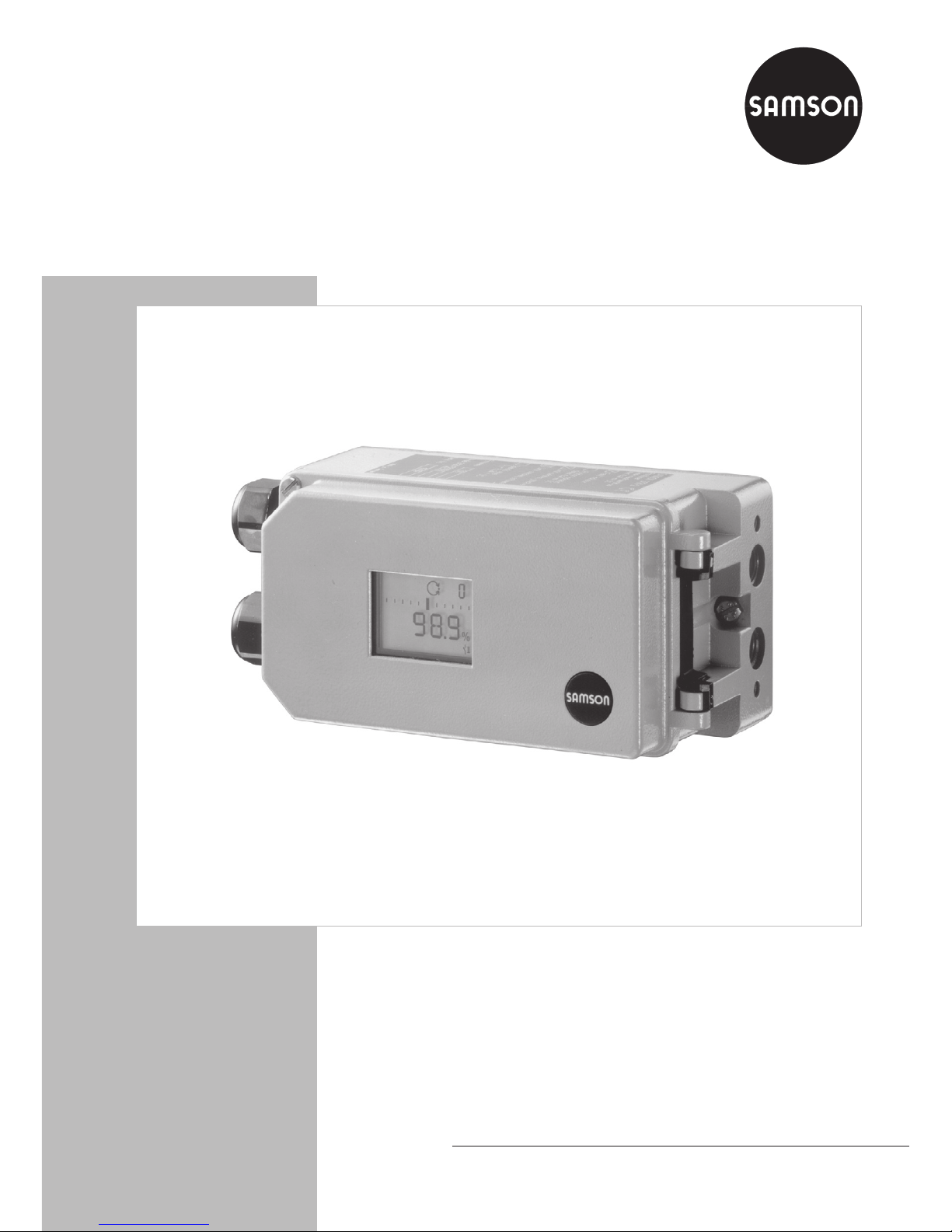
Series 3730/3731
Type 3730-3, Type 3730-6 and
Type 3731-3 (Ex d) Electropneumatic
Positioners
HART® Communication
Supplementary Conguration Instructions
Page 2
2 KH 8384-3 EN
Denition of the signal words used in these mounting and operating instructions
DANGER!
indicates a hazardous situation which,
if not avoided, will result in death or
serious injury.
WARNING!
indicates a hazardous situation which,
if not avoided, could result in death or
serious injury.
NOTICE
indicates a property damage message.
Note:
Supplementary explanations, information and tips
Page 3

KH 8384-3 EN 3
Contents
1 General ........................................................................................................4
1.1 HART
®
revisions .............................................................................................4
2 Device status and response code ....................................................................5
2.1 Communication status ....................................................................................5
2.2 Response code ...............................................................................................6
2.3 Device status ..................................................................................................7
3 Universal commands .....................................................................................8
3.1 Command 0 (Read Unique Identier) ..............................................................8
3.2 Command 1 (Read Primary Variable) .............................................................8
3.3 Command 3 (Read Dynamic Variables and Loop Current) ................................9
3.4 Command 33 (Read Device Variables) ..........................................................10
3.5 Command 38 (Reset Conguration Change Flag) ..........................................10
3.6 Command 48 (Read Additional Status) .........................................................11
3.6.1 Type 3730-3 and Type 3731-3 .....................................................................11
3.6.2 Type 3730-6 ...............................................................................................15
3.7 Starting and assessing the partial stroke test (PST) ...........................................21
3.7.1 Type 3730-3 and Type 3731-3 .....................................................................21
3.7.2 Type 3730-6 ...............................................................................................23
Page 4

General
4 KH 8384-3 EN
1 General
This Manual (KH 8384-3 EN) supplements the standard instructions for Types 3730-3, 3730-6
and 3731-3 Positioners and the associated diagnostics instructions.
Table 1: Associated documentation
Positioner Standard instructions Diagnostics instructions
Type 3730-3 u EB 8384-3 EN u EB 8389 EN
Type 3730-6 u EB 8384-6 EN u EB 8389-1 EN
Type 3731-3 u EB 8387-3 EN u EB 8389 EN
These instructions describe the most important HART® commands used together with the above
listed SAMSON positioners.
1.1 HART® revisions
Type3730-3 and Type3731-3
HART® revision5 is used in these positioners by default. Switchover to HART® revision6 is pos-
sible using the operator interface.
Type3730-6
HART® revision5 is used in this positioner by default. Switchover to HART® revision6 is not
possible.
Page 5

Device status and response code
KH 8384-3 EN 5
2 Device status and response code
The device response consists of 2 bytes. The rst byte represents either the communication status or the response code. If the most signicant bit (0x80) of the rst byte is set, this byte represents the communication status. If the bit is not set, the rst byte represents the response code
according to Table 3.
2.1 Communication status
A communication status is indicated by the response code when a communication error occurs.
Table 2: Communication status
Bit Denition
0x80 This bit must be set to 1 to show a communication error.
0x40 Vertical Parity Error – The parity of one or more of the bytes received by the device
was not uneven.
0x20 Overrun Error – At least one byte of data in the receive buffer of the UART was
overwritten before it was read (i.e. the slave did not process the incoming byte fast
enough).
0x10 Framing Error – The stop bit of one or more bytes received by the device was not de-
tected by the UART (i.e. a marking or 1 was not detected if a stop bit should have oc-
curred).
0x08 Longitudinal Parity Error – The Longitudinal Parity calculated by the device did not
match the Longitudinal Parity byte at the end of the message.
0x04 Reserved – set to zero.
0x02 Buffer Overow – The message was too long for the receive buffer of the device.
0x01 Reserved – set to zero.
If a communication error has not occurred, the response code contains a zero in the highest
valued bit and the code represents the following described code (0 to 127). The response code
is transferred in the rst byte of the data eld and indicates the status of the command. A zero
value indicates that the command is OK. A value unequal to zero means that there is an error
(see section 2.2 Response code on page 6).
Page 6

Device status and response code
6 KH 8384-3 EN
2.2 Response code
Table 3: Response codes
Value Denition
0 Success
2 Invalid selection
3 Passed parameter too large
4 Passed parameter too small
5 Too few data bytes received
6 Device-specic command error
7 In write protect mode
9 Invalid date code detected
10 Lower range value too low
11 Upper range value too high
12 Upper range value too low
16 Access restricted
18 Invalid units code
17 Invalid device variable index
20 Invalid extended command number
29 Invalid span
32 Busy
Page 7

Device status and response code
KH 8384-3 EN 7
2.3 Device status
This byte indicates the current status of the eld device.
Table 4: Device status
Bit Denition
0x80 The device has detected a serious error. This error endangers the functioning of the
device.
0x40 Conguration Changed – The device conguration has been changed. It can have
been changed by HART®, TROVIS-VIEW or using the local operation.
0x20 Cold Start – The device has been restarted.
0x10 More Status Available – Further status information is available in Code 48, Read
Additional Status Information.
0x08 Loop Current Fixed – The loop current is kept at a xed value and does not respond
anymore to the process variables.
0x04 Loop Current Saturated – The loop current has reached its top (or bottom) limit and
cannot rise (or fall) any further.
0x02 Non-Primary Variable Out of Limits – A device variable, other than that of the
Primary Variable, is beyond the operating limits of the device.
0x01 Primary Variable Out of Limits – The Primary Variable PV is beyond the operating
limits of the device.
Page 8

Universal commands
8 KH 8384-3 EN
3 Universal commands
3.1 Command 0 (Read Unique Identier)
Table 5: Command 0
Byte Denition
Byte 0 254
Byte 1 Manufacturer identication code (66 stands for SAMSON)
Byte 2 Device type (373x-3: 239, 3730-6: 238)
Byte 3 Minimum number of preambles (master to slave): 5
Byte 4 HART
®
revision number: 5
Byte 5 Device revision number: 1
Byte 6 Software version number: 1
Byte 7 Hardware version number: 8 (does not exist)
Byte 8 Flags: 0
Byte 9 to 11 Serial number of the device
Byte 12 Minimum number of preambles (slave to master)
Byte 13 Maximum number of device variables: 12
Byte 14 and 15 Counter for conguration change
Byte 16 Maintenance indicator (total valve travel exceeded)
3.2 Command 1 (Read Primary Variable)
Command 1 indicates the percent of the Primary Variable. The Primary Variable corresponds
to the reference variable in the default setting.
Table 6: Command 1
Byte Denition
Byte 0 Unit of the Primary Variable
Byte 1 to 4 Value of the Primary Variable
Page 9

Universal commands
KH 8384-3 EN 9
3.3 Command 3 (Read Dynamic Variables and Loop Current)
Command 3 reads the values of the four Dynamic Variables.
The assignment between the four Dynamic Variables and the selection from the twelve device
variables is made by command 51. Table 7 shows the currently available device variables.
In Type 373x-3, the reference variable is xed as the rst Dynamic Variable and cannot be
changed.
In Type 3730-6, the rst Dynamic Variable can be selected as required.
− Value 0 corresponds to the control value.
− Value 1 corresponds to the valve set point.
− Value 2 corresponds to the target position.
− Value 3 corresponds to the valve position.
− Value 4 corresponds to the error e.
− Value 5 corresponds to the total valve travel.
− Value 6 corresponds to the state of the binary input.
− Value 7 corresponds to the status of the internal solenoid valve/forced venting.
− Value 8 corresponds to the NAMUR condensed status.
− Value 9 corresponds to the current temperature.
− Value 10 corresponds to the sound level value (leakage sensor).
− Value 11 corresponds to the differential pressure.
Table 7: Command 3
Byte Denition
Byte 0 to 3 Reference variable in mA
Byte 4 Unit of the Primary Variable
Byte 5 to 8 Value of the Primary Variable
Byte 9 Unit of the Secondary Variable
Byte 10 to 13 Value of the Secondary Variable
Byte 14 Unit of the Tertiary Variable
Byte 15 to 18 Value of the Tertiary Variable
Byte 19 Unit of the Fourth Variable
Byte 20 to 23 Value of the Fourth Variable
Page 10

Universal commands
10 KH 8384-3 EN
3.4 Command 33 (Read Device Variables)
Command 33 allows a maximum of four of the device variables listed below to be read. The
indices of the variables to be read are specied in the readout.
Table 8: Command 33
Value Denition
Value 0 Control value
Value 1 Valve set point
Value 2 Target position
Value 3 Valve position
Value 4 Error e
Value 5 Total valve travel
Value 6 State of the binary input (optional)
Value 7 Status of the internal solenoid valve/forced venting (optional)
Value 8 NAMUR condensed status
Value 9 Current temperature
Value 10 Sound level value (leakage sensor)
Value 11 Differential pressure (Type 3730-6)
3.5 Command 38 (Reset Conguration Change Flag)
Command 38 resets the conguration change ag. This ag is always reset when a value is
written to the EEPROM.
Page 11

Universal commands
KH 8384-3 EN 11
3.6 Command 48 (Read Additional Status)
3.6.1 Type 3730-3 and Type 3731-3
The command 48 reads the additional device status. Four internal error bytes are returned
which, for example, contain error messages for the closed-loop operation (control loop er
-
ror etc.).
Table 9: Command 48 for Type 3730-3 and Type 3731-3
Byte Denition
Byte 0 to 3
1)
4 internal error bytes
Byte 4 Cold start ag
Byte 5 Positioner initialized ag
Bit 0: Positioner initialized ag (0/1)
Bit 1: Positioner initialized in Sub mode (0/1)
Byte 6 Extended device status (0/1)
Byte 7 Device operating mode (= 0)
Byte 8 to 10 Analog channel saturated (= 0)
Byte 11 to 13 Analog channel xed (= 0)
Byte 14 Device family status 0
Byte 15 Device family status 1
Byte 16 Device family status 2
Byte 17
2)
NAMUR status
Byte 18 to 30
2)
NAMUR status messages of the extended diagnostics
1)
Concerning bytes 0 to 3: These bytes contain four error bytes of the positioner. The bytes then have the
following meaning:
Byte Bit Error description Display menu item
0 0 x > range 50
1 Delta x < range 51
2 Attachment (mechanic/pneumatic unit) 52
3 Initialization time exceeded 53
4 Initialization/internal solenoid valve/forced venting 54
Page 12

Universal commands
12 KH 8384-3 EN
Byte Bit Error description Display menu item
0 5 Transit time too short 55
6 Pin position missing 56
7 Control loop error 57
1 0 Zero point 58
1 Autocorrection 59
2 Fatal error 60
3 – –
4 x signal 62
5 w too small 63
6 i/p converter 64
7 Hardware 65
2 0 Data memory 66
1 Test calculation 67
2 Control parameter 68
3 Potentiometer parameter 69
4 Calibration parameter 70
5 General parameters 71
6 – –
7 Internal device error 73
3 0 HART
®
parameter 74
1 Info parameters 75
2 No emergency mode 76
3 Program loading error 77
4 Options parameter 78
5 – –
6 Diagnostic parameter 80
7 – –
Page 13

Universal commands
KH 8384-3 EN 13
2)
Concerning bytes 17 to 30: NAMUR status messages of extended diagnostics
Byte Bit Message description
17 Bit 0 No message
Bit 1 Maintenance required
Bit 2 Maintenance demanded
Bit 3 Maintenance alarm
Bit 7 Function check
18 Bit 0 Supply pressure – OK
Bit 1 Supply pressure – Perhaps modied (TEST)
Bit 2 Supply pressure – Perhaps not enough (TEST)
Bit 3 Supply pressure – Perhaps not enough
Bit 4 Supply pressure – Working at full capacity
Bit 5 Supply pressure – Working at full capacity (TEST)
Bit 6 Supply pressure – Perhaps modied
19 Bit 0 Actuator springs – OK
Bit 1 Actuator springs – Perhaps spring stiffness reduced (spring failure) (TEST)
Bit 2 Actuator springs – Perhaps bias reduced (TEST)
Bit 3 Actuator springs – Perhaps bias increased (TEST)
Bit 4 Working at full capacity
Bit 5 Working at full capacity (TEST)
20 Bit 0 Shifting working range – OK
Bit 1 Shifting working range – Shifting working range to closing position
Bit 2 Shifting working range – Shifting working range to max. opening position
21 Bit 0 Friction – OK
Bit 1 Friction – Much higher over whole range
Bit 2 Friction – Much lower over whole range
Bit 3 Friction – Much higher over section
Bit 4 Friction – Much lower over section
Bit 5 Friction – Much higher over whole range (TEST)
Bit 6 Friction – Much lower over whole range (TEST)
Bit 7 Friction – Much higher over section (TEST)
Bit 8 Friction – Much lower over section (TEST)
Page 14

Universal commands
14 KH 8384-3 EN
Byte Bit Message description
22 Bit 0 Leakage in the pneumatics – OK
Bit 1 Leakage in the pneumatics – Perhaps existing (TEST)
Bit 2 Leakage in the pneumatics – Perhaps existing
Bit 3 Leakage in the pneumatics – Perhaps too large (TEST)
Bit 4 Leakage in the pneumatics – Perhaps too large
23 Bit 0 Limit working range – OK
Bit 1 Limit working range – Down
Bit 2 Limit working range – Up
Bit 3 Limit working range – Modication impossible (seizure)
24 Dynamic stress factor [%]
25 Bit 0 Inner leakage – OK
Bit 1 Inner leakage – Perhaps larger than origin
Bit 2 Inner leakage – Perhaps larger than origin (TEST)
Bit 3 Inner leakage – Perhaps existing
26 Bit 0 External leakage – OK
Bit 1 External leakage – Perhaps soon expected
Bit 2 External leakage – Perhaps expected
27 Bit 0 Observing end position – OK
Bit 1
Observing end position
– Zero point shift monotone down, average above
reference
Bit 2
Observing end position
– Zero point shift monotone up, average above ref-
erence
Bit 3 Observing end position
– Zero point alternates, average above reference
Bit 4
Observing end position
– Zero point shift monotone down, average below ref-
erence
Bit 5
Observing end position
– Zero point shift monotone up, average below refer-
ence
Bit 6 Observing end position
– Zero point alternates, average below reference
Page 15

Universal commands
KH 8384-3 EN 15
Byte Bit Message description
28 Bit 0 Positioner/valve mechanical connection – OK
Bit 1
Positioner/valve mechanical connection – No optimum travel transmission
(TEST)
Bit 2 Positioner/valve mechanical connection – Perhaps loose
Bit 3 Positioner/valve mechanical connection – Perhaps range limit
Bit 4 Positioner/valve mechanical connection – Perhaps loose (TEST)
29 Bit 0 Working range – OK
Bit 1 Working range – Mostly near closing position
Bit 2 Working range – Mostly near max. opening
Bit 3 Working range – Mostly closing position
Bit 4 Working range – Mostly max. opening
30 Bit 0 Partial stroke test (PST) – OK
Bit 1 Partial stroke test (PST) – Not OK
Note: The exact cause of failure must read out using CMD161 Refer to sec-
tion 3.7 on page 21.
3.6.2 Type 3730-6
The command 48 reads the extended device status. Six internal error bytes are returned which,
for example, contain error messages for the closed-loop operation (control loop error etc.).
Table 10: Command 48 for Type 3730-6
Byte Denition
Byte 0 to 5
1)
Internal error bytes
Byte 6 Extended device status (0/1)
Byte 7 Device operating mode (= 0)
Byte 8 to 10 Analog channel saturated (= 0)
Byte 11 to 13 Analog channel xed (= 0)
Byte 14 Device family status 0
Byte 15 Device family status 1
Byte 16 Device family status 2
Byte 17
2)
NAMUR status
Page 16

Universal commands
16 KH 8384-3 EN
Byte 18 to 29
2)
NAMUR status messages of the extended diagnostics
Byte 30 to 31
2)
PST: Results of current test
Byte 32 to 33
2)
FST: Results of current test
Byte 34 On/off (0 = no error/1 = an error has occurred)
Byte 35 Temperature monitoring
1)
Concerning bytes 0 to 5: these bytes contain six error bytes of the positioner. The bytes then have the
following meaning:
Byte Bit Message description Local
operation
0 Bit 0 x > range Code 50
Bit 1 Delta x < range Code 51
Bit 2 Attachment Code 52
Bit 3 Initialization time exceeded Code 53
Bit 4 Internal solenoid valve/forced venting/supply pressure Code 54
Bit 5 Transit time too short Code 55
0 Bit 6 Pin position/switch position Code 56
Bit 7 Control loop Code 57
1 Bit 0 Zero point Code 58
Bit 1 Inconsistent data memory Code 59
Bit 2 Internal device error Code 60
Bit 3 KP too small Code 61
Bit 4 x signal Code 62
Bit 5 SIL shutdown/w too small Code 63
Bit 6 i/p converter Code 64
Bit 7 Hardware Code 65
Page 17

Universal commands
KH 8384-3 EN 17
Byte Bit Message description Local
operation
2 Bit 0 Test calculation Code 67
Bit 1 Pressure sensor Code 72
Bit 2 No emergency mode Code 76
Bit 3 Valve signature canceled Code 81
Bit 4 PST/FST status Code 84
Bit 5 On/off error Code 85
Bit 6 SIL tests Code 86
Bit 7 – –
3 Bit 0 Set point outside range –
Bit 1 Binary input error status –
Bit 2 Total valve travel exceeded –
Bit 3 Operating mode not equal to Auto –
Bit 4 Cold start –
Bit 5 Positioner not initialized –
Bit 6 Positioner initialized in Sub mode –
Bit 7 – –
From this point onwards, the extended error messages are summarized in groups and sent as bits.
Byte Bit Message description Local operation
4 Bit 0 Supply pressure –
Bit 1 Defective actuator springs –
Bit 2 Shifting working range –
Bit 3 Friction change –
Bit 4 Pneumatic leakage –
Bit 5 Limit range –
Bit 6 Inner leakage –
Bit 7 External leakage –
Page 18

Universal commands
18 KH 8384-3 EN
Byte Bit Message description Local operation
5 Bit 0 Course of end position –
Bit 1 Positioner/valve mechanical connection –
Bit 2 Range –
Bit 3 Partial stroke test (PST)/full stroke test (FST) –
Bit 4 Temperature monitoring –
Bit 5 – –
Bit 6 – –
Bit 7 – –
2)
Concerning bytes 18 to 33: NAMUR status messages of the extended diagnostics
Byte Bit Message description
17 Bit 0 No message
Bit 1 Maintenance required
Bit 2 Maintenance demanded
Bit 3 Maintenance alarm
Bit 7 Function check
18 Bit 0 Supply pressure – OK
Bit 1 Supply pressure – Perhaps modied (TEST)
Bit 2 Supply pressure – Perhaps not enough (TEST)
Bit 3 Supply pressure – Perhaps not enough
Bit 4 Supply pressure – Working at full capacity
Bit 5 Supply pressure – Working at full capacity (TEST)
Bit 6 Supply pressure – Perhaps modied
19 Bit 0 Actuator springs – OK
Bit 1 Actuator springs – Perhaps spring stiffness reduced (spring failure) (TEST)
Bit 2 Actuator springs – Perhaps bias reduced (TEST)
Bit 3 Actuator springs – Perhaps bias increased (TEST)
Bit 4 Working at full capacity
Bit 5 Working at full capacity (TEST)
Page 19

Universal commands
KH 8384-3 EN 19
Byte Bit Message description
20 Bit 0 Shifting working range – OK
Bit 1 Shifting working range – Shifting working range to closing position
Bit 2 Shifting working range – Shifting working range to max. opening position
21 Bit 0 Friction – OK
Bit 1 Friction – Much higher over whole range
Bit 2 Friction – Much lower over whole range
Bit 3 Friction – Much higher over section
Bit 4 Friction – Much lower over section
Bit 5 Friction – Much higher over whole range (TEST)
Bit 6 Friction – Much lower over whole range (TEST)
Bit 7 Friction – Much higher over section (TEST)
Bit 8 Friction – Much lower over section (TEST)
22 Bit 0 Leakage in the pneumatics – OK
Bit 1 Leakage in the pneumatics – Perhaps existing (TEST)
Bit 2 Leakage in the pneumatics – Perhaps existing
Bit 3 Leakage in the pneumatics – Perhaps too large (TEST)
Bit 4 Leakage in the pneumatics – Perhaps too large
23 Bit 0 Limit working range – OK
Bit 1 Limit working range – Down
Bit 2 Limit working range – Up
Bit 3 Limit working range – Modication impossible (seizure)
24 Dynamic stress factor [%]
25 Bit 0 Inner leakage – OK
Bit 1 Inner leakage – Perhaps larger than origin
Bit 2 Inner leakage – Perhaps larger than origin (TEST)
Bit 3 Inner leakage – Perhaps existing
26 Bit 0 External leakage – OK
Bit 1 External leakage – Perhaps soon expected
Bit 2 External leakage – Perhaps expected
Page 20

Universal commands
20 KH 8384-3 EN
Byte Bit Message description
27 Bit 0 Observing end position – OK
Bit 1
Observing end position
– Zero point shift monotone down, average above
reference
Bit 2
Observing end position
– Zero point shift monotone up, average above ref-
erence
Bit 3 Observing end position
– Zero point alternates, average above reference
Bit 4
Observing end position
– Zero point shift monotone down, average below ref-
erence
Bit 5
Observing end position
– Zero point shift monotone up, average below refer-
ence
Bit 6 Observing end position
– Zero point alternates, average below reference
28 Bit 0 Positioner/valve mechanical connection – OK
Bit 1
Positioner/valve mechanical connection – No optimum travel transmission
(TEST)
Bit 2 Positioner/valve mechanical connection – Perhaps loose
Bit 3 Positioner/valve mechanical connection – Perhaps range limit
Bit 4 Positioner/valve mechanical connection – Perhaps loose (TEST)
29 Bit 0 Working range – OK
Bit 1 Working range – Mostly near closing position
Bit 2 Working range – Mostly near max. opening
Bit 3 Working range – Mostly closing position
Bit 4 Working range – Mostly max. opening
Byte Message description
30/31 00000000 00000001 No PST performed
00000000 00000010 PST successful performed
00000000 00000100 x cancelation
00000000 00001000 Δp out cancelation
00000000 00010000 Tolerance band exceeded
Page 21

Universal commands
KH 8384-3 EN 21
Byte Message description
30/31 00000000 00100000 Max. test duration exceeded
00000000 01000000 Test cancelled manually
00000000 10000000 Measured data memory full
00000001 00000000 Cancel internal solenoid valve/forced venting
00000010 00000000 Cancelled by control loop error
00000100 00000000 Set point start difference too high
00001000 00000000 Set point change
00010000 00000000 Current too low
00100000 00000000 Max. breakaway time exceeded
01000000 00000000 Perm. time until step end exceeded
10000000 00000000 Supply pressure too low
3.7 Starting and assessing the partial stroke test (PST)
3.7.1 Type 3730-3 and Type 3731-3
Send Receive
Byte 1 Byte 2
Start PST
Cmd 168
0x89 –
–
Stop PST
Cmd 168
0x9D –
–
PST Info
Cmd 171
0x01 0x19 0/1: PST not activated/running
PST test status
Cmd 161
0x00 0xD9 See Table 11
Current PST results
− Command 181 Subcommand 467
Byte 0 –
Byte 1 to 4: Dead time (rising)
Page 22

Universal commands
22 KH 8384-3 EN
− Command 181 Subcommand 468
Byte 0 –
Byte 1 to 4: T63 (rising)
− Command 181 Subcommand 469
Byte 0 –
Byte 1 to 4: T98 (rising)
− Command 181 Subcommand 470
Byte 0 –
Byte 1 to 4: Rise time step (rising)
− Command 181 Subcommand 471
Byte 0 –
Byte 1 to 4: Settling time step (rising)
− Command 151 Subcommand 290 (oat)
Byte 0 –
Byte 1 to 4: Overshoot (rising)
− Command 181 Subcommand 472
Byte 0 –
Byte 1 to 4: Dead time (falling)
− Command 181 Subcommand 473
Byte 0 –
Byte 1 to 4: T63 (falling)
− Command 181 Subcommand 474
Byte 0 –
Byte 1 to 4: T98 (falling)
− Command 181 Subcommand 475
Byte 0 –
Byte 5 to 8: Rise time step (falling)
− Command 181 Subcommand 476
Byte 0 –
Byte 9 to 12: Settling time step (falling)
− Command 151 Subcommand 296 (oat)
Byte 0 –
Byte 1 to 4: Overshoot (falling)
Page 23

Universal commands
KH 8384-3 EN 23
Table 11: PST status (bit = 1 means that the description applies)
Bit Description
00000000 00000001 No PST performed
00000000 00000010 PST successful performed
00000000 00000100 x cancelation
00000000 00001000 y cancelation
00000000 00010000 Tolerance band exceeded
00000000 00100000 Max. test duration exceeded
00000000 01000000 Test cancelled manually
00000000 10000000 Measured data memory full
00000001 00000000 Cancel internal solenoid valve/forced venting
00000010 00000000 Canceled by control loop error
00000100 00000000 Set point start difference too high
00001000 00000000 Set point change
00010000 00000000 Current too low
00100000 00000000 Max. breakaway time exceeded
01000000 00000000 Perm. time until step end exceeded
10000000 00000000 Supply pressure too low
3.7.2 Type 3730-6
Send
Receive
Byte 1 Byte 2
Start PST
Cmd 168
0x89 – –
Stop PST
Cmd 168
0x9D – –
PST info
Cmd 171
0x01 0x19 0/1: PST not activated/running
PST measurement results
Cmd 157
0xA4 – See Table 12
PST test status
Cmd 161
0x00 0xD9 See page21 onwards
Page 24

Universal commands
24 KH 8384-3 EN
Table 12: PST measurement results
Byte Measurement results
Byte 0 –
Byte 1 to 4 Overshoot (rising) oat
Byte 5 to 8 Dead time (rising)
Byte 9 to 12 –
Byte 13 to 16 T86 (rising)
Byte 17 to 20 Settling time (rising)
Byte 21 to 24 –
Byte 25 to 28 Overshoot (falling) oat
Byte 29 to 32 Dead time (falling)
Byte 33 to 36 –
Byte 37 to 40 T86 (falling)
Byte 41 to 44 Settling time (falling)
Page 25

Page 26

Page 27

Page 28

SAMSON AG · MESS- UND REGELTECHNIK
Weismüllerstraße 3 · 60314 Frankfurt am Main, Germany
Phone: +49 69 4009-0 · Fax: +49 69 4009-1507
Internet: http://www.samson.de
KH 8384-3 EN
2015-02-18
 Loading...