

Samson 3725 series Mounting And Operating Instructions
Series 3725
Electropneumatic Positioner
Type 3725
Mounting and
Operating Instructions
EB 8394 EN (1300-1621)
Firmware version 1.0x
Edition February 2012
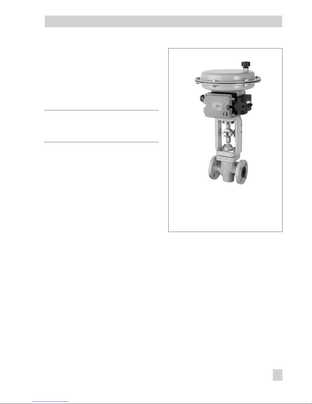
Fig. 1 · Type 3725 Positioner

2 EB 8394 EN
WARNING!
indicates a hazardous situation which, if not
avoided, could result in death or serious
injury.
NOTICE
indicates a property damage message.
Note: Supplementary explanations,
information and tips
Definitions of the signal words used in these instructions

Contents Page
1 Safety instructions . . . . . . . . . . . . . . . . . . . . . . . . . . . 6
2 Article code . . . . . . . . . . . . . . . . . . . . . . . . . . . . . . 7
3 Design and principle of operation. . . . . . . . . . . . . . . . . . . . 8
3.1 Technical data. . . . . . . . . . . . . . . . . . . . . . . . . . . . . 10
4 Attachment to the control valve – Mounting parts and accessories . . . 12
4.1 Direct attachment . . . . . . . . . . . . . . . . . . . . . . . . . . . 14
4.1.1 Type 3277-5 Actuator . . . . . . . . . . . . . . . . . . . . . . . . . 14
4.1.2 Type 3277 Actuator . . . . . . . . . . . . . . . . . . . . . . . . . . 17
4.2 Attachment according to IEC 60534-6 . . . . . . . . . . . . . . . . . 20
4.3 Attachment to Type 3372 Actuator (V2001) . . . . . . . . . . . . . . 23
4.4 Attachment to rotary actuators . . . . . . . . . . . . . . . . . . . . . 24
4.5 Mounting parts and accessories . . . . . . . . . . . . . . . . . . . . 26
5 Connections . . . . . . . . . . . . . . . . . . . . . . . . . . . . . . 28
5.1 Pneumatic connections . . . . . . . . . . . . . . . . . . . . . . . . . 28
5.1.1 Signal pressure gauges . . . . . . . . . . . . . . . . . . . . . . . . 28
5.1.2 Supply pressure . . . . . . . . . . . . . . . . . . . . . . . . . . . . 28
5.2 Electrical connections . . . . . . . . . . . . . . . . . . . . . . . . . 29
6 Operation. . . . . . . . . . . . . . . . . . . . . . . . . . . . . . . 32
6.1 Operator controls . . . . . . . . . . . . . . . . . . . . . . . . . . . 32
7 Start-up – Settings. . . . . . . . . . . . . . . . . . . . . . . . . . . 33
7.1 Enabling configuration. . . . . . . . . . . . . . . . . . . . . . . . . 34
7.2 Setting the volume restriction Q . . . . . . . . . . . . . . . . . . . . 35
7.3 Adapting the display. . . . . . . . . . . . . . . . . . . . . . . . . . 35
7.4 Entering the opening direction . . . . . . . . . . . . . . . . . . . . . 36
7.5 Defining the direction of action. . . . . . . . . . . . . . . . . . . . . 36
7.6 Limiting the signal pressure. . . . . . . . . . . . . . . . . . . . . . . 36
7.7 Setting other parameters . . . . . . . . . . . . . . . . . . . . . . . 37
7.8 Initialization . . . . . . . . . . . . . . . . . . . . . . . . . . . . . . 38
7.9 Zero calibration . . . . . . . . . . . . . . . . . . . . . . . . . . . . 39
7.10 Manual mode . . . . . . . . . . . . . . . . . . . . . . . . . . . . . 40
7.11 Reset . . . . . . . . . . . . . . . . . . . . . . . . . . . . . . . . . 41
EB 8394 EN 3
Contents

7.12 Faults . . . . . . . . . . . . . . . . . . . . . . . . . . . . . . . . . 42
8 Code list . . . . . . . . . . . . . . . . . . . . . . . . . . . . . . . 43
9 Maintenance . . . . . . . . . . . . . . . . . . . . . . . . . . . . . 47
10 Servicing explosion-protected devices . . . . . . . . . . . . . . . . . 47
11 Dimensions in mm . . . . . . . . . . . . . . . . . . . . . . . . . . 48
11.1 Fixing levels according to VDI/VDE 3845 (September 2010) . . . . . . 49
Test certificates . . . . . . . . . . . . . . . . . . . . . . . . . . . . 50
4 EB 8394 EN
Contents

EB 8394 EN 5
Firmware revisions
Firmware revisions
1.02 (previous) 1.03 (new)
Internal revisions
1 Safety instructions
For your own safety, follow these instructions concerning the mounting, start up and operation of the positioner:
4
The positioner is to be mounted, started up or operated only by trained and experienced personnel familiar with the product.
According to these Mounting and Operating Instructions, trained personnel refers to
individuals who are able to judge the work they are assigned to and recognize possible dangers due to their specialized training, their knowledge and experience as well
as their knowledge of the relevant standards.
4
Explosion-protected versions of this positioner may only be operated by personnel
who have undergone special training or instructions or who are authorized to work
on explosion-protected devices in hazardous areas.
4
Any hazards that could be caused by the process medium, the operating pressure, the
signal pressure or by moving parts of the control valve are to be prevented by means
of the appropriate measures.
4
If inadmissible motions or forces are produced in the actuator as a result of the supply
pressure, the supply pressure must be restricted by means of a suitable supply pressure reducing station.
4
Proper shipping and appropriate storage are assumed.
To avoid damage to any equipment, the following also applies:
4
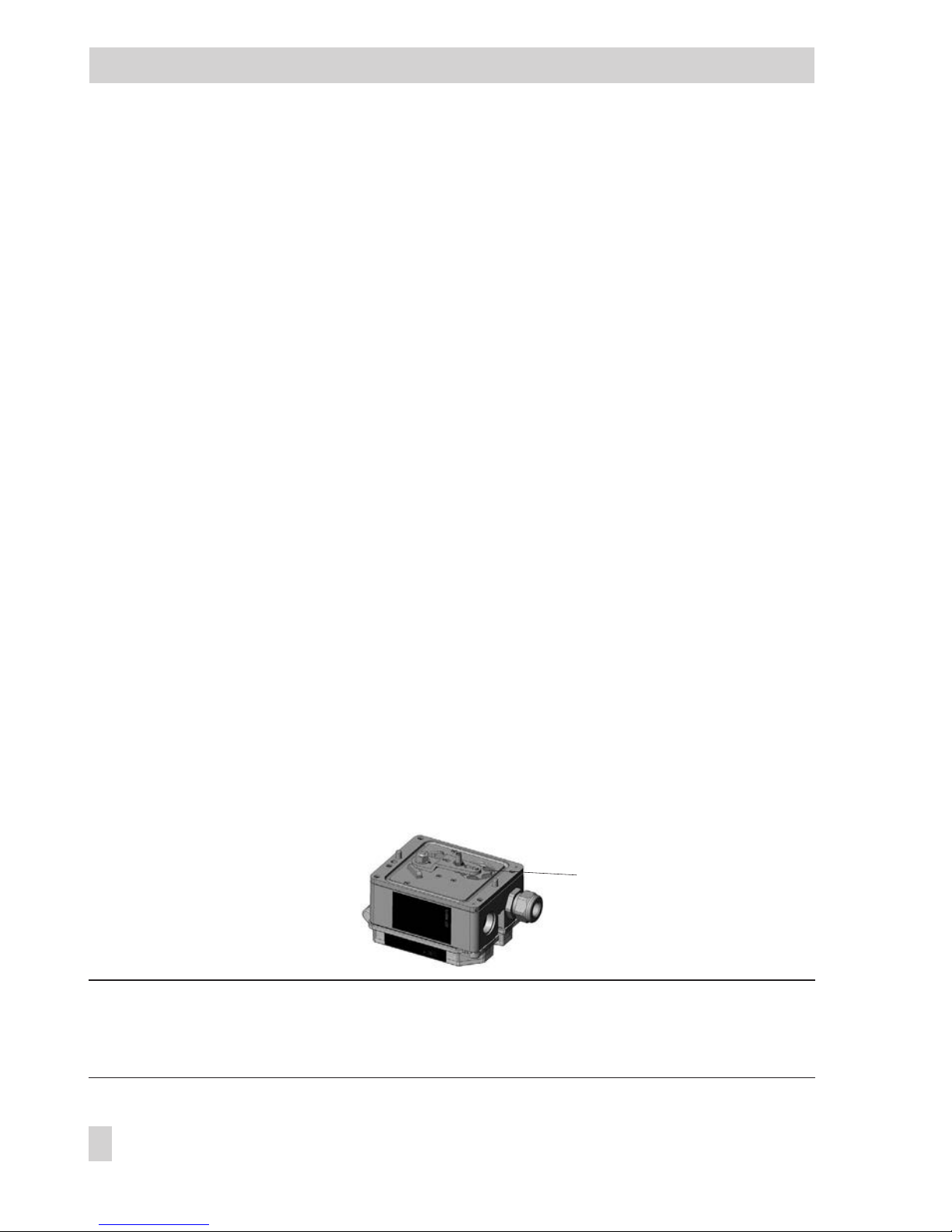
Do not operate the positioner with the back of the positioner/vent opening facing upwards.
The vent opening must not be sealed when the positioner is installed on site.
4
Do not ground electric welding equipment near to the positioner.
Note: The device with a CE marking fulfills the requirements of the Directives 94/9/EC
(ATEX) and 89/336/EEC (EMC).
The Declaration of Conformity is available on request.
6 EB 8394 EN
Safety instructions
Vent opening
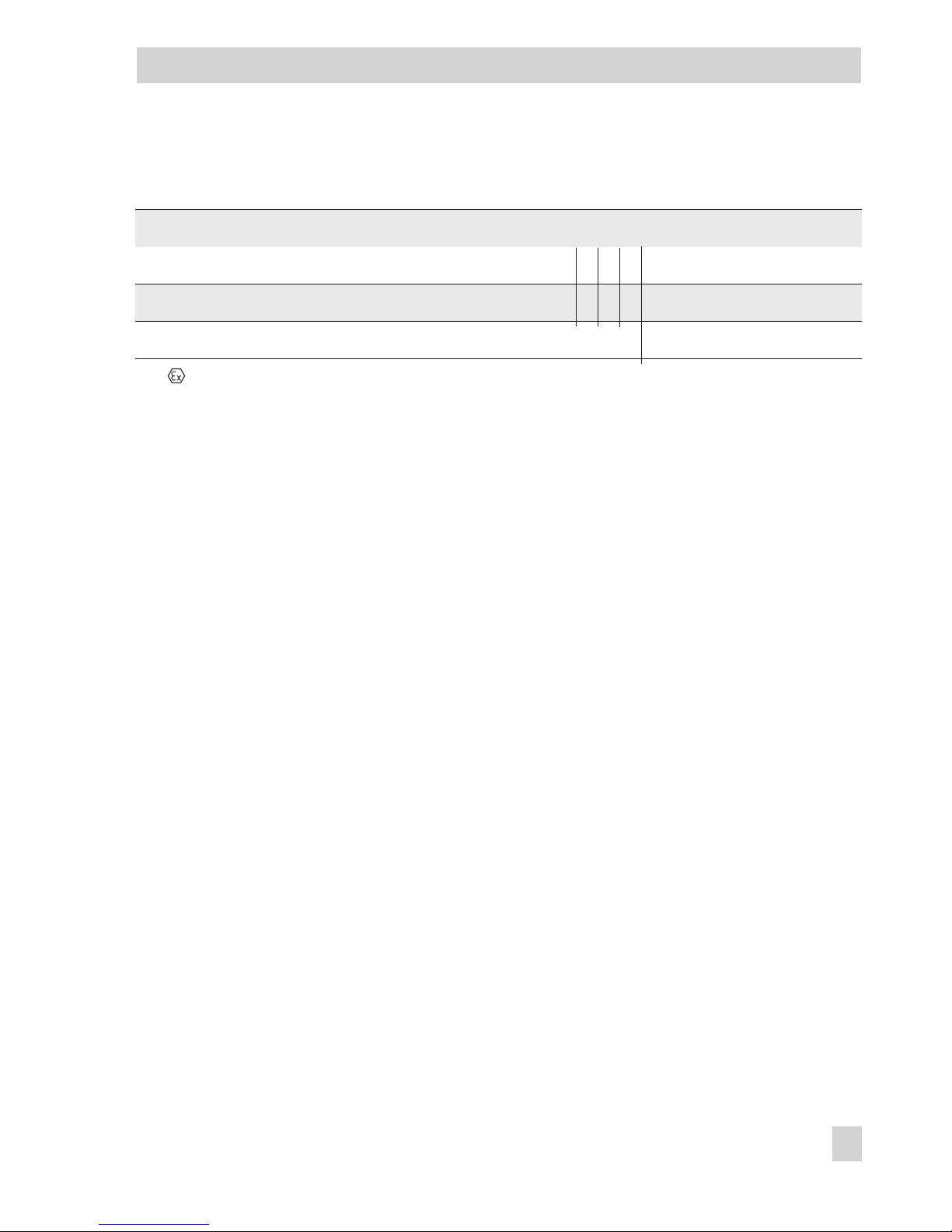
2 Article code
EB 8394 EN 7
Article code
Positioner
Type 3725-
xxx00000009999
With LCD and autotune, 4 to 20 mA reference variable
Explosion protection*
Without
000
II 2 G Ex ia IIC T4 acc. to ATEX
1100
* Other approvals in preparation

3 Design and principle of
operation
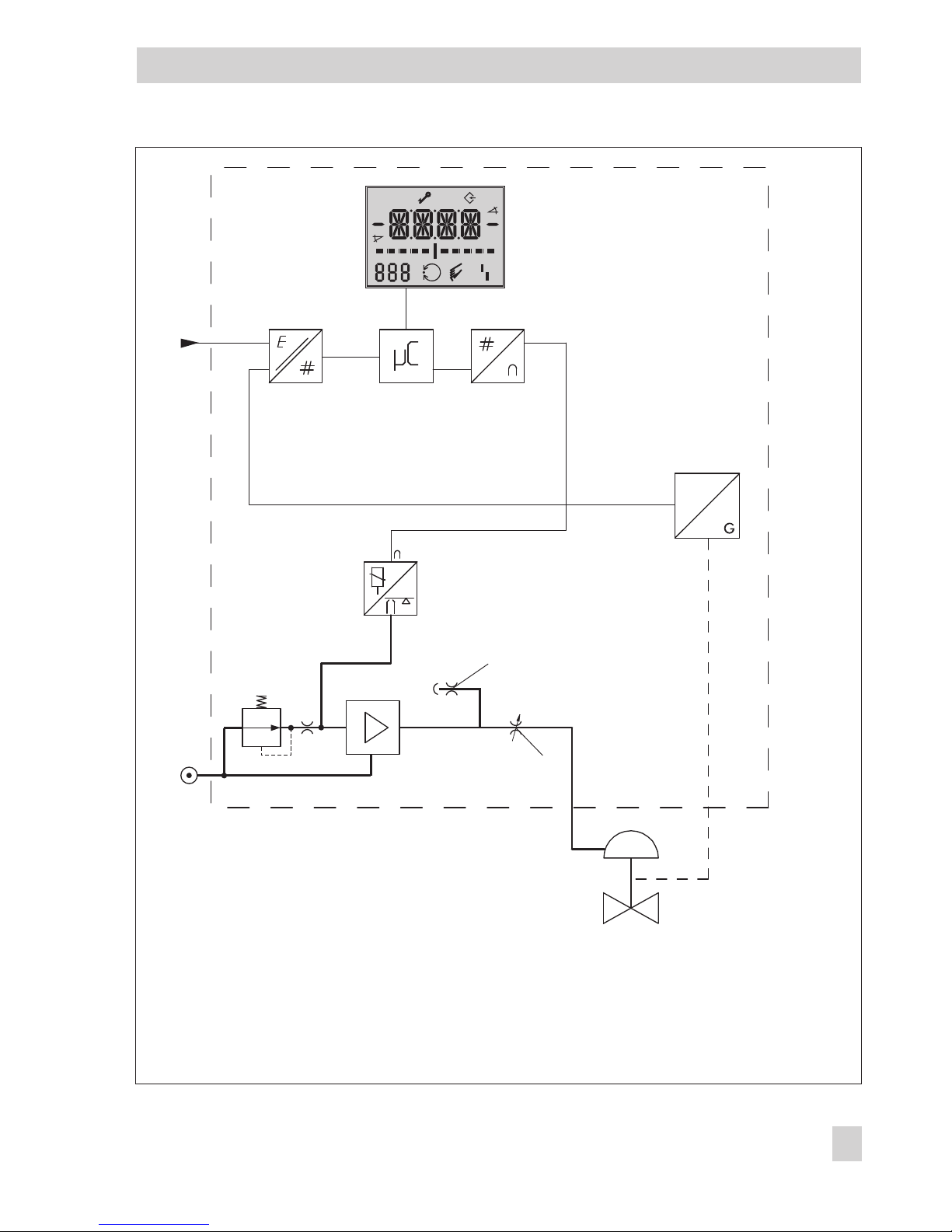
The electropneumatic positioner is mounted
on pneumatic control valves. It is used to assign the valve stem position (controlled variable x) to the control signal (reference variable w). The electric control signal received
from a control system is compared to the
travel or rotational angle of the control valve
and a signal pressure (output variable y) is
produced for the pneumatic actuator.
The positioner consists of an anisotropic
magnetoresistive (AMR) sensor (2), an analog i/p converter (7) with a downstream
booster and the electronics unit with
microcontroller (4).
The travel or opening angle is measured by
the pick-up lever connected to a magnet and
a non-contact AMR sensor (2) installed in
the housing and the electronics.
The motion of the pick-up lever causes the
direction of the magnetic field to change.
This change is sensed by the AMR sensor.
The microprocessor determine the momentary valve position from this information.
The position of the valve is transmitted to the
microcontroller (4) over the A/D converter
(3). The PD control algorithm in the microprocessor (4) compares this actual position
to the 4 to 20 mA control signal (reference
variable) after it has been converted by the
A/D converter (3).
In case of a system deviation, the operation
of the i/p converter (6) is changed so that
the actuator (1) is filled or vented by the
downstream air capacity booster (7).
The pneumatic air capacity booster (7) and
the pressure regulator (8) are supplied with
supply air.
The output signal pressure supplied by the
booster can be limited to 2.4 bar by software.
The volume restriction Q (10) is used to optimize the positioner by adapting it to the actuator size.
Tight-closing function
The pneumatic actuator is completely filled
with air or vented as soon as the reference
variable falls below 1 % or exceeds 99 %
(see end positions set over parameter codes
P10 and P11).
Air to open (ATO): P10®ON; P11®OFF
Air to close (ATC): P10®OFF; P11®ON
8 EB 8394 EN
Design and principle of operation
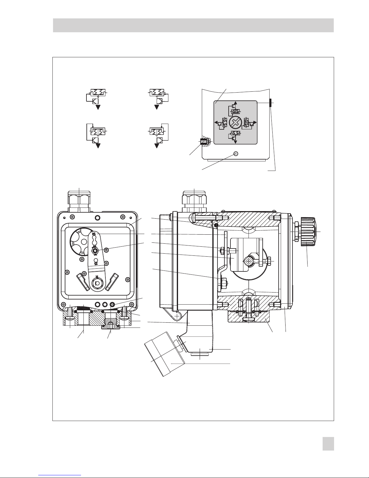
EB 8394 EN 9
Design and principle of operation
%
S
mm
%
mm
Q
3
4
11
6
7
8
10
1
w
9
x
y
2
5
Fig. 2 · Functional diagram
1 Control valve
2 AMR sensor
3 A/D converter
4 Microcontroller
5 D/A converter
6 i/p converter
7 Air capacity booster
8 Pressure regulator
9 Fixed restriction
10 Volume restriction
11 Display
3.1 Technical data
10 EB 8394 EN
Technical data
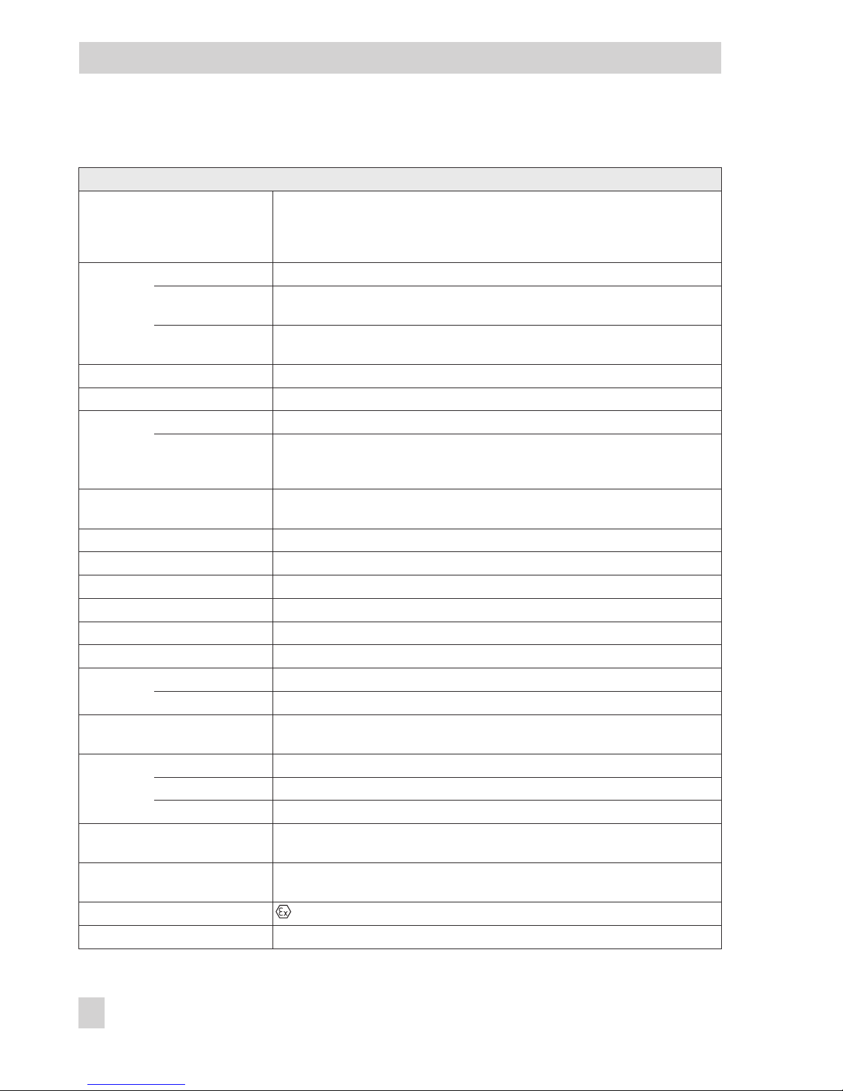
Type 3725 Positioner
Travel, adjustable Direct attachment to Type 3277 Actuator: 3.75 to 30 mm
Attachment acc. to IEC 60 534-6-1 (NAMUR): 3.75 to 50 mm
Attachment to Type 3372 Actuator: 15/30 mm
Attachment to rotary actuators: 24 to 100°
Reference
variable w
Signal range 4 to 20 mA · Two-wire device with reverse polarity protection
Split range
operation
4 to 11.9 mA and 12.1 to 20 mA
Static destruction
limit
±
33 V
Minimum current 3.8 mA
Load impedance
£
6 V (corresponds to 300Wat 20 mA)
Supply air
Supply pressure 1.4 to 7 bar (20 to 105 psi)
Air quality
acc. to
ISO 8573-1 (2001)
Max. particle size and density: Class 4 · Oil content: Class 3
Pressure dew point: Class 3 or at least 10 K below the lowest ambient temperature
to be expected
Signal pressure (output)
0 bar up to the capacity of the supply pressure · Can be limited to approx. 2.4
bar by software
Characteristics 3 characteristics for globe valves · 9 characteristics for rotary valves
Hysteresis
£
0.3 %
Sensitivity
£
0.1 %
Transit time < 0.5 s not permissible for initialization, adaptation using volume restriction
Direction of action w/x reversible
Air consumption
£
100 l
n
/h with a supply pressure up to 6 bar and a signal pressure of 0.6 bar
Air output
capacity
Actuator pressurized AtDp = 6 bar: 8.5 m
n
³/h·AtDp = 1.4 bar: 3.0 mn³/h·K
Vmax (20 °C)
= 0.09
Actuator vented AtDp = 6 bar: 14.0 m
n
³/h · AtDp = 1.4 bar: 4.5 mn³/h · K
Vmax (20 °C)
= 0.15
Permissible ambient temperature
–25 to +80 °C
Limits in test certificates additionally apply for explosion-protected devices.
Influences
Temperature£0.15 %/10 K
Supply air None
Vibrations£0.25 % up to 2000 Hz and 4 g according to IEC 770
Electromagnetic compatibility
Complying with the requirements of EN 61000-6-2, EN 61000-6-3, EN 61326-1
and NAMUR Recommendation NE 21
Electrical connections
One M20x1.5 cable gland for 6 to 12 mm clamping range
Cage clamp terminals for 0.2 to 1.5 mm² wire cross-sections
Explosion protection II 2 G Ex ia IIC T4
Degree of protection IP 66
EB 8394 EN 11
Technical data
Materials
Housing Polyphthalamide (PPA)
Cover Polycarbonate, transparent
External parts Stainless steel 1.4571 and 1.4301
Cable gland Polyamide, black, M20 x 1.5
Weight Approx. 1.0 kg
4 Attachment to the control
valve – Mounting parts and
accessories
WARNING!
Attach the positioner, keeping the following
sequence:
1. Mount the positioner on the control valve
2. Connect the supply air
3. Connect the electrical power
4. Perform the start-up settings
The positioner is suitable for the following
types of attachment:
4
Direct attachment to SAMSON
Type 3277 Actuator
4
Attachment to actuators according to
IEC 60534-6 (NAMUR)
4
Attachment to Type 3372 Linear Actuator (V2001 Valve Series)
4
Attachment to rotary actuators according
to VDI/VDE 3845
NOTICE
Attach the positioner to the control valve,
observing the following instructions to avoid
damaging the positioner.
–
Use only the mounting parts/accessories
listed in the table (section 4.5). Observe
the type of attachment!
–
Observe the assignment between lever
and pin position!
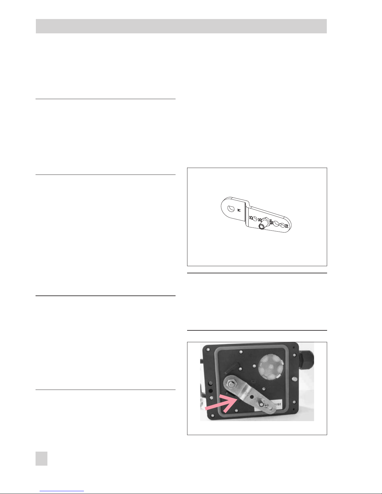
Lever and pin position
The positioner is adapted to the actuator
and to the rated travel by the lever on the
back of the positioner and the pin inserted
into the lever.
The travel tables show the maximum adjustment range at the positioner. The travel that
can be implemented at the valve is additionally restricted by the selected fail-safe position and the required compression of the actuator springs.
The positioner is standard equipped with the
lever M (pin position 35).
NOTICE
When undoing the lever, e.g. with a screwdriver, do not move the shaft by moving the
lever past the mechanical stops. Otherwise,
the internal stops may be damaged.
12 EB 8394 EN
Attachment to the control valve – Mounting parts and accessories
Fig. 3 · Lever M with pin position 35
Fig. 4 · Stop for lever
EB 8394 EN 13
Attachment to the control valve – Mounting parts and accessories
Travel tables
Note: The lever M is included in the scope of delivery.
Direct attachment to Type 3277-5 and Type 3277 Actuators
Actuator size Rated travel Adjustment range at positioner
Required
lever
Assigned
pin position
[cm²] [mm] Min. Travel Max.
120 7.5 5.3 to 15.0 M 25
120/240/350 15 7.5 to 21.2 M 35
355/700 30 10.6 to 30.0 M 50
Attachment according to IEC 60534-6 (NAMUR)
SAMSON Type 3271 Actuator Travel of other valves [mm] Required
lever
Assigned
pin position
Actuator size
[cm²]
Rated travel
[mm]
min. max.
120 7.5 3.75 10.6 S 17
120 7.5 5.3 25.0 M 25
120/240/350 15
5.0 35.0 M 35
700 7.5
700 15 10.8 50.0 M 50
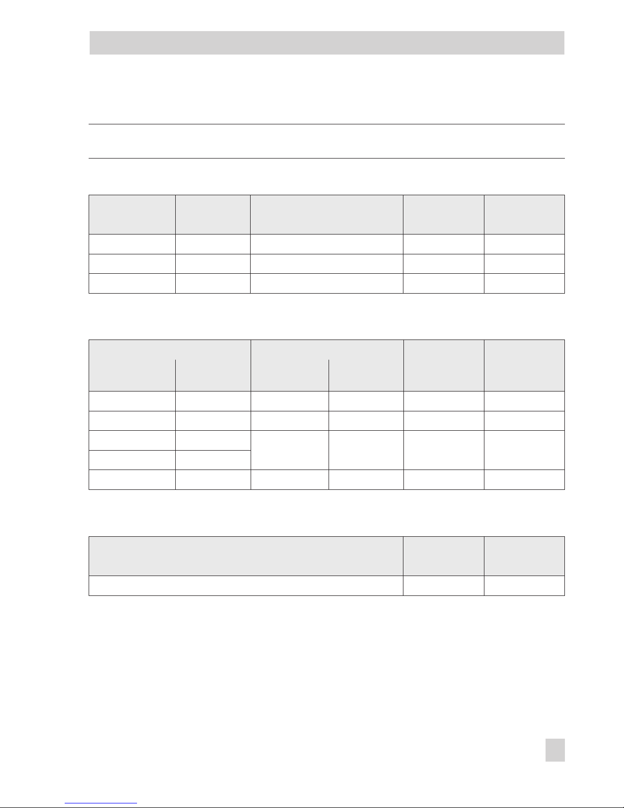
Attachment to rotary actuators according to VDI/VDE 3845
Rotary actuators
Required
lever
Assigned
pin position
Min. Opening angle Max.
24 to 100° M 90°

4.1 Direct attachment
4.1.1 Type 3277-5 Actuator
Refer to Table 1 on page 26 for required
mounting parts and accessories.
Note the travel table on page 13!
Actuator with 120 cm²
Depending on the type of positioner attachment, the signal pressure is routed either left
or right of the yoke through a bore to the
actuator diaphragm.
Depending on the fail-safe action of the actuator "Actuator stem extends" or "Actuator
stem retracts" (valve closes or opens if the
supply air fails), the switchover plate (9)
must first be attached to the actuator yoke.
Align the switchover plate with the corresponding symbol for left or right attachment
according to the marking (view looking onto
the switchover plate).
1. Mount connecting plate (6) or pressure
gauge bracket (7) with pressure gauges
onto the positioner, making sure both
seal rings (6.1) are seated properly.
2. Insert the screw (4) on the back of the
positioner into the hole below it (park
position) (see Fig. 6) and seal the signal
pressure output on the connecting plate
(6) or on the pressure gauge bracket (7)
with the stopper (5) included in the accessories.
3. Place follower clamp (3) on the actuator
stem, align and screw tight so that the
mounting screw is located in the groove
of the actuator stem.
4. 15 mm travel: Keep the follower pin (2)
at lever M (1) on the back of the
positioner in the pin position 35 (delivered state).
7.5 mm travel: Remove the follower pin
(2) from the pin position 35, reposition it
in the hole for pin position 25 and screw
tight.
5. Insert formed seal (15) into the groove of
the positioner housing.
6. Place positioner on the actuator in such
a manner that the follower pin (2) rests
on top of the follower clamp (3). During
which, press on the ribbed area shown
in Fig. 5 to lock the pick-up lever in the
top position.
The lever (1) must rest on the follower
clamp with spring force.
Mount the positioner on the actuator using the two fixing screws.
7. Mount cover (11) on the other side.
Make sure that the vent plug points
downwards when the control valve is installed to allow any condensed water
that collects to drain off.
14 EB 8394 EN
Attachment to the control valve – Mounting parts and accessories
Fig. 5 · Locking the pick-up lever in position
EB 8394 EN 15
Attachment to the control valve – Mounting parts and accessories
Symbols
Actuator stem
extends
Attachment left Attachment right
Actuator stem
retracts
1 Lever
1.1 Nut
1.2 Disk spring
2 Follower pin
3 Follower clamp
4 Screw
5 Stopper
6 Connecting plate
6.1 Seal rings
7 Pressure gauge
bracket
8 Press. gauge
mounting kit
9 Switchover plate
for actuator
11 Cover
14 Gasket
15 Formed seal
16 Vent plug
Switchover plate (9)
Signal pressure
input for right
attachment
Marking
Signal pressure
input for left
attachment
Note:
Always use the connecting plate (6)
included in the accessories to connect
supply and output.
Never screw threaded parts directly
into the housing.
911
Supply 9 Output 38
5
6
7
3
2
1
15
6.1
1.1
1.2
8
4
16
Fig. 6 · Direct attachment – Signal pressure connection for Type 3277-5 Actuator with 120 cm²
Additional solenoid valve
If a solenoid valve is additionally mounted
onto the actuator, the signal pressure port at
the back of the positioner must be sealed. To
do this, unscrew the screw located in the
middle hole (screw in park position) and
screw it into the signal pressure port to seal
it.
In this case, the signal pressure must be
routed from the signal pressure output to the
actuator over the connecting plate (6) or
pressure gauge bracket (7). The connecting
plate (accessories for the actuator) replaces
the switchover plate (9).
Note: The switchover plate or connecting
plate are accessories for the actuator
(120 cm²) listed in Table 1 on page 26.
16 EB 8394 EN
Attachment to the control valve – Mounting parts and accessories
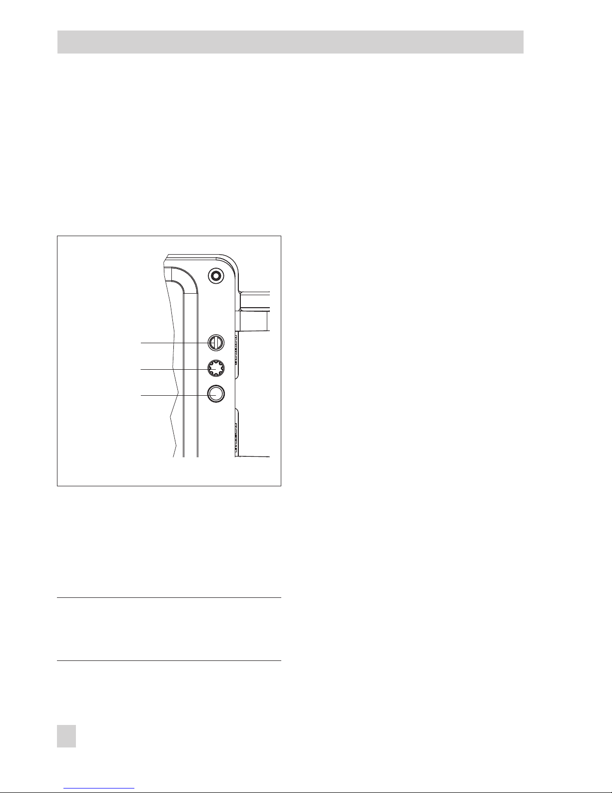
Fig. 7 · Signal pressure port and screw
park position
Screw plug (4)
(signal pressure port)
Park position
Mounting screw
4.1.2 Type 3277 Actuator
Refer to Table 2 on page 26 for the required
mounting parts as well as the accessories
with their order numbers.
Note the travel table on page 13!
Note: The actuators with 240 to 700 cm² effective areas are described on the following
pages.
EB 8394 EN 17
Attachment to the control valve – Mounting parts and accessories
Fig. 8 · Type 3277 Actuator with Type 3725
Positioner (direct attachment)
 Loading...