

Page 1
EB 8395 EN
Translation of original instructions
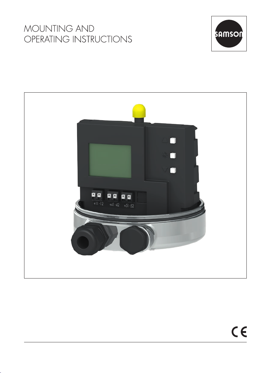
Type3724 Positioner (cover removed)
Type3724 Electropneumatic Positioner
Firmware version 1.01
Edition October 2018
Page 2
Note on these mounting and operating instructions
These mounting and operating instructions assist you in mounting and operating the device
safely. The instructions are binding for handling SAMSON devices.
Î For the safe and proper use of these instructions, read them carefully and keep them for
later reference.
Î If you have any questions about these instructions, contact SAMSON‘s After-sales Service
Department (aftersalesservice@samson.de).
The mounting and operating instructions for the devices are included in
the scope of delivery. The latest documentation is available on our website
at www.samson.de > Service & Support > Downloads > Documentation.
Denition of signal words
!
DANGER
Hazardous situations which, if not avoided,
will result in death or serious injury
!
WARNING
Hazardous situations which, if not avoided,
could result in death or serious injury
2 EB 8395 EN
!
NOTICE
Property damage message or malfunction
Note
Additional information
Tip
Recommended action
Page 3

Contents
1 Safety instructions and measures ...................................................................5
1.1 Notes on possible personal injury ...................................................................7
1.2 Notes on possible property damage ................................................................7
2 Markings on the device .................................................................................9
2.1 Nameplate ....................................................................................................9
2.2 Article code ...................................................................................................9
3 Design and principle of operation ................................................................10
3.1 Technical data .............................................................................................12
3.2 Dimensions in mm ........................................................................................14
4 Measures for preparation ............................................................................15
4.1 Unpacking ..................................................................................................15
4.2 Transporting ................................................................................................15
4.3 Storage .......................................................................................................15
5 Mounting and start-up .................................................................................16
5.1 Pneumatic connections..................................................................................16
5.1.1 Supply pressure ...........................................................................................16
5.2 Electrical connections ...................................................................................18
5.2.1 Accessories .................................................................................................18
5.2.2 Selecting cables and wires ............................................................................19
5.2.3 Cable entry .................................................................................................19
6 Operation ...................................................................................................20
6.1 Operating controls .......................................................................................20
7 Operating the positioner ..............................................................................22
7.1 Adapting the display ....................................................................................23
7.2 Enabling conguration to change parameters.................................................23
7.3 Adjusting the volume restriction Q .................................................................24
7.4 Entering the opening direction/direction of action ..........................................25
7.5 Entering the direction of action ......................................................................25
7.6 Limiting the signal pressure ...........................................................................25
7.7 Adjusting the limit contacts ...........................................................................26
7.8 Setting other parameters ...............................................................................26
7.9 Initialization ................................................................................................27
7.10 Zero calibration ...........................................................................................28
7.11 Manual mode ..............................................................................................29
7.12 Reset ...........................................................................................................30
EB 8395 EN 3
Page 4

Contents
8 Servicing.....................................................................................................31
8.1 Preparation for return shipment .....................................................................31
8.2 Firmware update..........................................................................................31
9 Malfunction .................................................................................................32
9.1 Error codes ..................................................................................................33
9.2 Emergency action ........................................................................................34
10 Decommissioning and removal ....................................................................35
10.1 Decommissioning .........................................................................................35
10.2 Removing the positioner ...............................................................................35
10.3 Disposal ......................................................................................................35
11 Appendix ....................................................................................................36
11.1 After-sales service ........................................................................................36
11.2 Code list ......................................................................................................37
4 EB 8395 EN
Page 5

Safety instructions and measures
1 Safety instructions and measures
Intended use
The Type3724 Positioner is delivered as a ready-mounted unit on Type3379 Pneumatic
Piston Actuators. It is used to assign the valve position to the control signal. The device is
designed to operate under exactly dened conditions (e.g. operating pressure, temperature).
Therefore, operators must ensure that the positioner is only used in applications where the
operating conditions correspond to the technical data. In case operators intend to use the
positioner in other applications or conditions than specied, contact SAMSON.
SAMSON does not assume any liability for damage resulting from the failure to use the device for its intended purpose or for damage caused by external forces or any other external
factors.
Î Refer to the technical data for limits and elds of application as well as possible uses.
Reasonably foreseeable misuse
The Type3724 Positioner is not suitable for the following applications:
− Use outside the limits dened during sizing and by the technical data
Furthermore, the following activities do not comply with the intended use:
− Use of non-original spare parts
− Performing maintenance activities not specied by SAMSON
Qualications of operating personnel
The positioner must be mounted, started up and serviced by fully trained and qualied
personnel only; the accepted industry codes and practices are to be observed. According to
these mounting and operating instructions, trained personnel refers to individuals who are
able to judge the work they are assigned to and recognize possible hazards due to their
specialized training, their knowledge and experience as well as their knowledge of the
applicable standards.
Personal protective equipment
No personal protective equipment is required for the direct handling of the positioner. Work
on the control valve may be necessary when mounting or removing the device.
Î Observe the requirements for personal protective equipment specied in the valve docu-
mentation.
Î Check with the plant operator for details on further protective equipment.
EB 8395 EN 5
Page 6

Safety instructions and measures
Revisions and other modications
Revisions, conversions or other modications of the product are not authorized by SAMSON.
They are performed at the user's own risk and may lead to safety hazards, for example. Fur-
thermore, the product may no longer meet the requirements for its intended use.
Safety features
Upon failure of the air supply or electric signal, the positioner vents the actuator, causing the
valve to move to the fail-safe position determined by the actuator.
Warning against residual hazards
The positioner has direct inuence on the control valve. To avoid personal injury or property
damage, plant operators and operating personnel must prevent hazards that could be
caused in the control valve by the process medium, the operating pressure, the signal pres-
sure or by moving parts by taking appropriate precautions. They must observe all hazard
statements, warning and caution notes in these mounting and operating instructions, especially for installation, start-up and service work.
If inadmissible motions or forces are produced in the pneumatic actuator as a result of the
supply pressure level, it must be restricted using a suitable supply pressure reducing station.
Responsibilities of the operator
The operator is responsible for proper operation and compliance with the safety regulations.
Operators are obliged to provide these mounting and operating instructions to the operating
personnel and to instruct them in proper operation. Furthermore, the operator must ensure
that operating personnel or third persons are not exposed to any danger.
Responsibilities of operating personnel
Operating personnel must read and understand these mounting and operating instructions as
well as the specied hazard statements, warning and caution notes. Furthermore, the operating personnel must be familiar with the applicable health, safety and accident prevention
regulations and comply with them.
Referenced standards and regulations
The device with a CE marking fullls the requirements of the Directive 2014/30/EU and the
Directive 2014/35/EU. The Declaration of Conformity is available on request.
Referenced documentation
The following documents apply in addition to these mounting and operating instructions:
− The mounting and operating instructions of the components on which the positioner is
mounted (valve, actuator, valve accessories etc.).
6 EB 8395 EN
Page 7

Safety instructions and measures
1.1 Notes on possible personal injury
!
WARNING
Risk of personal injury due to moving parts on the valve.
During initialization of the positioner and during operation, the actuator stem moves
through its entire travel range. Injury to hands or ngers is possible if they are inserted
into the valve.
Î During initialization, do not touch any moving valve parts.
1.2 Notes on possible property damage
!
NOTICE
Risk of malfunction due to incorrect sequence during start-up.
The positioner can only work properly if the mounting and start-up are performed in the
prescribed sequence.
Î Perform mounting and start-up as described in section16 in page5.
Unauthorized manual adjustments to the positioner will damage it!
Î Do not move the pick-up rod manually.
Dirty supply air will cause the positioner to malfunction!
Î Only use supply air that is dry and free of oil and dust.
Î Blow through all air pipes and hoses thoroughly before connecting them.
An incorrect electric signal will damage the positioner.
A current source must be used to provide the electrical power for the positioner.
Î Only use a current source and never a voltage source.
EB 8395 EN 7
Page 8

Safety instructions and measures
Incorrect assignment of the terminals will damage the positioner and will lead to malfunction.
For the positioner to function properly, the prescribed terminal assignment must be observed.
Î Connect the electrical wiring to the positioner according to the prescribed terminal
assignment.
A reference variable above or below the static destruction limit will damage the positioner.
Î Keep the reference variable within the static destruction limit of ±32V.
Malfunction due to initialization not yet completed.
The initialization causes the positioner to be adapted to the mounting situation. After initialization is completed, the positioner is ready to use.
Î Initialize the positioner on the rst start-up.
Î Re-initialize positioner after changing any parameters.
The process is disturbed by the movement of the actuator stem.
Î Do not perform the initialization while the process is running. First isolate the plant by
closing the shut-off valves.
Risk of positioner damage due to incorrect grounding of the electric welding equipment.
Î Do not ground electric welding equipment near to the positioner.
8 EB 8395 EN
Page 9
Markings on the device
2 Markings on the device
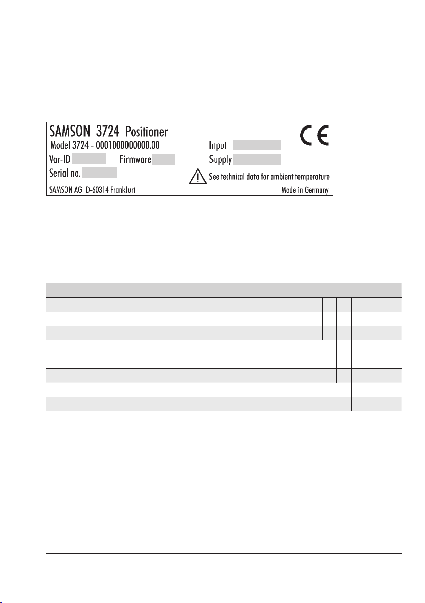
2.1 Nameplate
4
1
3
1 Conguration ID
2 Firmware version
3 Serial number
4 Reference variable
5 Supply
2
5
2.2 Article code
Positioner Type3724- 0 0 0 0 0 0 x 0 0 0 0 0
Housing material
Housing: 1.4409 · Cover: 1.4404 0
Surface nish
Micro-bead blasted 1
Polished (R
Permissible ambient temperature
–20 to +80°C 0
Degree of protection
IP 65
1)
≤0.6µm) 2
a
1)
(only applies in combination with Type3379 Pneumatic Actuator) 0
Pending
EB 8395 EN 9
Page 10

Design and principle of operation
3 Design and principle of oper-
ation
The Type3724 Positioner is delivered as a
ready-mounted unit on Type3379 Pneumatic
Piston Actuators.
The positioner is used to assign the valve po-
sition (controlled variable x) to the control
signal (reference variable w). The positioner
compares the electric control signal of a control system to the travel of the control valve
(1) and issues a signal pressure (output variabley) for the pneumatic actuator.
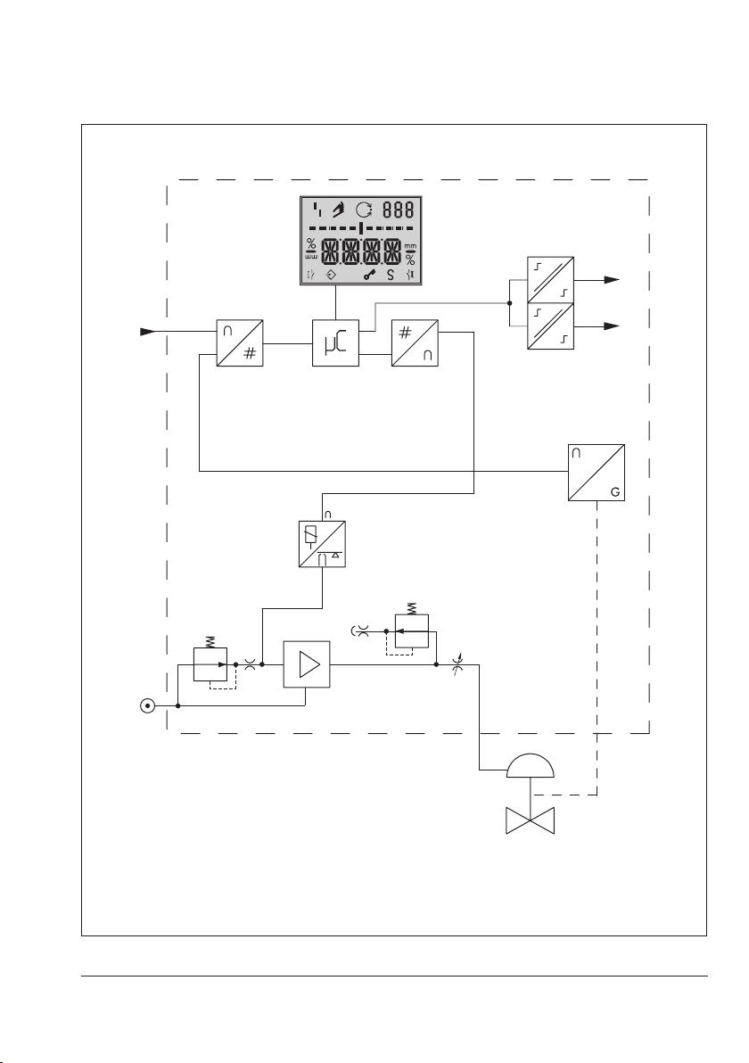
The positioner mainly consists of the follow-
ing components (see Fig.1):
− Magnetoresistive sensor (2)
− Analog i/p converter (6) with a down-
stream air capacity booster (7)
− Electronics unit with microcontroller (4)
− Software limit contacts (12)
The travel is measured by an internal pick-up
rod, which is connected to a magnet, as well
as a non-contact magnetoresistive sensor
and the downstream electronics.
The motion of the pick-up rod causes the di-
rection of the magnetic eld to change. This
change is sensed by the sensor (2). The elec-
tronics unit determines the current valve position from this information.
The position of the valve is transmitted to the
microcontroller (4) over its A/D converter
(3). The microcontroller contains a modied
PID controller which compares the actual
valve position with the 4 to 20mA control
signal. The resulting output value is passed
on to the D/A converter. In case of a system
deviation, the activation of the i/p module
(6) is changed so that the actuator (1) is
pressurized or vented accordingly over the
downstream air capacity booster (7). The
supply air is supplied to the booster (7) and
the pressure regulator (8).
!
NOTICE
Unauthorized manual adjustments to the positioner will damage it!
Do not move the pick-up rod manually.
The output signal pressure supplied by the
booster can be limited to 2.3bar by software.
The volume restriction Q (10) is used to optimize the positioner by adapting it to the ac-
tuator.
Tight-closing function
The pneumatic actuator is completely lled
with air or vented as soon as the reference
variable falls below 1% or exceeds 99%
(see set point cutoff in P10 and P11 parameter codes).
10 EB 8395 EN
Page 11
Design and principle of operation
w
11
12
A1
A2
3
8
1 Control valve
2 Sensor
3 A/D converter
4 Microcontroller
5 D/A converter
6 i/p converter
4
6
7
7 Air capacity booster
8 Pressure regulator
9 Flow regulator
10 Volume restriction
11 Display
12 Limit contacts
5
2
9
10
Q
y
1
x
Fig.1: Circuit diagram
EB 8395 EN 11
Page 12

Design and principle of operation
3.1 Technical data
Table1: General technical data
Positioner
Attachment Type3379 piston Ø: 63mm · Effective area: 31cm²
Type3379 piston Ø: 90mm · Effective area: 63cm²
Travel 4 to 16mm, adjustable in steps of 0.5mm
Reference variable w
(reverse polarity protection)
Static destruction limit ±32V
Minimum current
Load impedance Max. 6.3V
Supply air
Air quality acc. to
ISO8573-1
Signal pressure (output) 0 bar up to the supply pressure minus 0.4bar
Characteristic Three selectable characteristics:
Transit time Only for actuators with initialization time > 0.4s
Direction of action w/x reversible
Perm. ambient temperature –20 to +80°C
Electromagnetic
compatibility
Degree of protection IP 65
Compliance
Materials
Housing 1.4409
Cover 1.4404
Dome (visual indicator) Polycarbonate
Weight (without actuator) Approx. 1.2kg
1)
For faster actuators, a volume restriction must be used. Otherwise, the initialization cannot be
performed successfully.
2)
Pending
4 to 20mA signal range · Two-wire device
Split-range operation 4 to 11.9mA and 12.1 to 20mA
3.8mA
Supply air: 1.4 to 7bar (20 to 105psi)
Max. particle size and density: Class 4 · Oil content: Class 3 · Pressure
dew point: Class 3 or at least 10K below the lowest ambient
temperature to be expected
Can be limited to approx. 2.3bar by software
Linear · Equal percentage · Reverse equal percentage
1)
Complying with EN 61000-6-2, EN 61000-6-3 and NAMUR
Recommendation NE21
2)
(only applies in combination with Type3379 Pneumatic
Actuator)
12 EB 8395 EN
Page 13

Design and principle of operation
Table2: Limit contacts
Binary contacts Two software limit contacts (min., max.)
Version Reverse polarity protection, galvanic isolation
Adjustment range 0 to 100% (see section7.7 on page 26)
Step size 0.5%
Static destruction limit ± 32V
Signal
state
For connection to
No response Non-conducting (highly resistive), I < 100µA
Response
− Binary input of a PLC acc. to IEC 61131-2,
= 400mW
P
max
Conducting (R = 330Ω)
EB 8395 EN 13
Page 14

Design and principle of operation
135
3.2 Dimensions in mm
130
285
Ød
Ø108
Fig.2: Dimensional drawings of Type3724 Positioner with Type3379 Pneumatic Piston Actuator
Actuator Piston Ø Ød
Type3379
63mm 69mm
90mm 94mm
14 EB 8395 EN
Page 15

Measures for preparation
4 Measures for preparation
After receiving the shipment, proceed as follows:
1. Check the scope of delivery. Compare
the shipment received with the delivery
note.
2. Check the shipment for transportation
damage. Report any transportation damage.
4.1 Unpacking
!
NOTICE
Risk of positioner damage due to foreign
particles entering it.
Do not remove the packaging and protective
lm/protective caps until immediately before
mounting and start-up.
1. Remove the packaging from the positioner.
2. Dispose of the packaging in accordance
with the valid regulations.
4.2 Transporting
4.3 Storage
!
NOTICE
Risk of positioner damage due to improper
storage.
− Observe storage instructions.
− Avoid long storage times.
− Contact SAMSON in case of different stor-
age conditions or long storage periods.
Storage instructions
− Protect the positioner against external in-
uences (e.g. impact, shocks, vibration).
− Do not damage the corrosion protection
(coating).
− Protect the positioner against moisture
and dirt. In damp spaces, prevent condensation. If necessary, use a drying
agent or heating.
− Observe storage temperature depending
on the permissible ambient temperature
(see technical data in section3.1).
− Store positioner with closed cover.
− Seal pneumatic and electrical connec-
tions.
− Protect the positioner against external in-
uences (e.g. impact).
− Protect the positioner against moisture
and dirt.
− Observe transport temperature depend-
ing on the permissible ambient tempera-
ture (see technical data in section3.1).
EB 8395 EN 15
Page 16

Mounting and start-up
5 Mounting and start-up
!
NOTICE
Risk of malfunction due to incorrect sequence
of mounting, installation and start-up.
Observe the prescribed sequence.
Note
The unit consisting of the Type3724 Positioner, Type3379 Actuator and valve is
ready assembled on delivery.
In special cases, the valve and actuator are
delivered separately and must be assembled
on site. In this case, read the associated
valve documentation.
Î Sequence to be kept on installing and
starting up the positioner:
1. Remove the protective caps from the
pneumatic connections.
2. Perform pneumatic installation.
Î Section5.1 onwards
3. Perform electrical installation.
Î Section5.2 onwards
4. Perform settings.
Î Section7 onward
5.1 Pneumatic connections
The Type3724 Positioner is delivered ready
mounted on the Type3379 Pneumatic Piston
Actuator. The pneumatic connections of the
positioner are connected internally to the
connections of the actuator.
The pneumatic connections of the actuator
are used (see Mounting and Operating Instructions of the Type3379 Pneumatic Piston
Actuator uEB8315) for start-up (see section7 on page22).
!
NOTICE
Dirty supply air will cause the positioner to
malfunction!
Only use supply air that is dry and free of oil
and dust.
Blow through all air pipes and hoses thor-
oughly before connecting them.
5.1.1 Supply pressure
The required supply air pressure depends on
the bench range and the actuator's operat-
ing direction (fail-safe action). The bench
range is written on the nameplate either as
the bench range or signal pressure range.
The operating direction is marked FA or FE
or by a symbol.
16 EB 8395 EN
Page 17

FA: actuator stem extends (air to open/
ATO)
Fail-close (for globe and angle valves):
Required supply pressure = Upper bench
range value + 0.4bar, minimum 1.4bar.
FE: actuator stem retracts (Air to close/ATC)
Fail-open (for globe and angle valves):
For tight-closing valves, the maximum signal
pressure pst
is roughly estimated as fol-
max
lows:
Mounting and start-up
pst
max
= F +
d² · π · ∆p
4 · A
[bar]
d = Seat diameter [cm]
∆p = Differential pressure across the
valve [bar]
A = Actuator area [cm²]
F = Upper bench range value [bar]
If there are no specications, calculate as
follows:
Recommended supply pressure =
Upper bench range value + 1bar
Note
The signal pressure at the output (38) of the
positioner can be restricted to approx.
2.3bar by setting P9 parameter code to
ON.
EB 8395 EN 17
Page 18

Mounting and start-up
5.2 Electrical connections
!
NOTICE
An incorrect electric signal will damage the
positioner.
Only use a current source and never a voltage source.
Î Connect the wiring as shown in Fig.3.
Î Select cables and wires as described in
section5.2.2.
Î Insert cables as described in sec-
tion5.2.3.
!
NOTICE
Incorrect assignment of the terminals will
damage the positioner and will lead to malfunction.
Connect the electrical wiring to the positioner according to the prescribed terminal assignment.
5.2.1 Accessories
Description Order no.
Cable gland:
Black plastic, M16x1.5
Plastic part
8808-1010
+11 –12
+11/–12: mA control signal
+41/–42: Limit contact 1 (min.)
+51/–52: Limit contact 2 (max.)
Fig.3: Electrical connections Fig.4: Cage clamp terminals
+41 –42
+51 –52
18 EB 8395 EN
Page 19

Mounting and start-up
5.2.2 Selecting cables and
wires
The minimum radial thickness of the conductor insulation must be suitable for the conductor diameter and type of insulation. It
must be at least 0.2mm.
The diameter of an individual wire in a
ne-stranded conductor must not be smaller
than 0.1mm.
Protect the conductor ends against splicing,
e.g. by using wire-end ferrules.
5.2.3 Cable entry
The M16x1.5 cable gland is designed for a
clamping range of 6 to 12mm.
The cage clamp terminals hold wire
cross-sections of 0.2 to 1.5mm².
Î Unscrew the cover and remove it.
Î To unlock the cage clamp terminals:
place a slotted screwdriver on the plastic
part (Fig.4) and lightly push it into the
terminal block.
Î Insert or remove the wire without force.
Î Guide wires for the reference variable to
the terminals +11 and –12 located on
the housing.
!
NOTICE
A reference variable above or below the
static destruction limit will damage the positioner.
Keep the reference variable within the static
destruction limit of ±32V.
Mounting the cover
Î Mount the cover, briey turn it counter-
clockwise to center it. Turn it clockwise to
rmly close it.
EB 8395 EN 19
Page 20

Operation
6 Operation
The positioner is operated by three pushbut-
tons for menu navigation on the display (see
Fig.5):
Up
:
Conrm
:
Down
:
Î To adapt the air capacity, adjust the vol-
ume restriction (see section 7.3).
6.1 Operating controls
Press or button to select a parameter
code (P0 to P20). Then press
conrm the selected code.
button to
Manual mode Closed-loop control
To save changes to parameters in a non-volatile memory, proceed as follows:
Î After changing parameters, press or
button to change to Code P0 or
Î wait three minutes until the display re-
turns automatically to P0.
Note
− The
icon on the display indicates that
the changed parameter settings have not
yet been saved in the non-volatile memory.
− The selected parameter code remains ac-
tive until you change the setting or exit the
parameter code.
− After changing settings in P2, P4 and P8
parameter codes, the positioner must be
re-initialized.
Fault
Bar graph/
system deviation
Limit contact 1 (min.)
Settings not yet
saved in a nonvolatile memory
Fig.5: Display with all readings
Operation
locked
Fail-safe position
active
Parameter/error code
Unit/sign
Limit contact 2 (max.)
20 EB 8395 EN
Page 21

Cover
Positioner
Operation
Pick-up rod
Pushbuttons
Terminals
Vent plug
Actuator
Fig.6: Type3724 Positioner mounted on Type3379 Pneumatic Piston Actuator
EB 8395 EN 21
Page 22

Operating the positioner
Volume restriction Q
The volume restriction serves to adapt the air
output capacity to the size of the actuator.
Two xed settings are possible (refer to section 7.3).
Reading
Display Meaning
ESC Stop
Err Faults
LOW w too low
MAN Manual mode
MAX Maximum range
RST Reset
INIT Initialization
ON/OFF Activated/deactivated
ZERO Zero calibration
Icons which are assigned to certain codes
and functions are indicated on the display.
The bar elements indicate the system devia-
tion that depends on the sign (+/–) and the
value.
One bar element appears per 1% set point
deviation.
If the positioner has not yet been initialized,
the position of the pick-up rod is indicated in
the operating range of ±10mm.
If the fault indication icon
press
or until ERR is displayed to view
is displayed,
the relevant E0 to E15 error code(s) (see
code list in section 33 on page9.1).
7 Operating the positioner
!
NOTICE
The process is disturbed by the movement of
the actuator stem.
Do not perform the initialization while the
process is running. First isolate the plant by
closing the shut-off valves.
Î Perform pneumatic connections on the
actuator as described in u EB8315.
Î Connect the supply air to signal pressure
connection.
Î Check whether a vent plug or silencer is
screwed into the exhaust port.
Î Connect the 4 to 20mA signal.
à Terminals +11/–12
Î Connect software limit contacts, if appli-
cable.
à Terminals +41/–42:
(limit contact 1, min.)
à Terminals +51/–52:
(limit contact 2, max.)
Note
− LOW on the display indicates that the
reference variable is lower than 3.8mA.
− The positioner is ready for operation with
its default settings for most applications.
22 EB 8395 EN
Page 23

Operating the positioner
Reading after connecting the electrical signal
Code P0 is displayed. The fault indication
icon and S (fail-safe position) appear on the
display when the positioner has not yet been
initialized. The reading indicates the position
of the pick-up rod in the operating range of
±10mm.
Reading when the posi-
tioner has not yet been
initialized
Code P0 and the valve position in % appear
on the display after connecting the electrical
signal to an initialized positioner.
Initialization successfully
completed, positioner runs
in closed-loop operation
Note
The positioner has a function to monitor the
working range. If the pick-up rod moves too
close to the mechanical stops (risk of me-
chanical damage), the positioner vents the
actuator and the valve moves to its fail-safe
position (S displayed together with E8 error
code).
7.1 Adapting the display
The display reading direction can be rotated
by 180°. If the displayed data appear upside down, proceed as follows:
Press
or until Code P1 appears.
Code P1: Reading direction
Press to conrm the selected code.
P1 blinks.
Press or until the display is set in the
desired direction.
Press to conrm display direction.
7.2 Enabling conguration to
change parameters
Before changing parameter settings in an
initialized positioner, conguration must be
enabled rst by selecting Code P19.
LOCK and the key icon in-
dicate that the conguration is locked.
Press or until Code P19 appears.
Press
P19 blinks.
Press until OPEN is displayed.
Touch
to conrm the selected code.
to unlock operation.
EB 8395 EN 23
Page 24

Operating the positioner
If no settings are entered within three minutes, the enabled conguration function becomes invalid.
7.3 Adjusting the volume restriction Q
The volume restriction Q serves to adapt the
air output capacity to the size of the actua-
tor:
− Actuators with a transit time < 0.4s re-
quire a restricted air ow rate.
Setting to MIN
− Actuators with a transit time ≥ 0.4s do
not require the air ow rate to be restricted.
Setting to MAX
Intermediate settings are not permitted.
!
NOTICE
Malfunction due to changing the volume restriction setting!
Re-initialize positioner after changing the
volume restriction setting.
Position of the volume restriction Q
MIN position:
Arrow points toward the positioner
MAX position:
Arrow points away from the
positioner
Fig.7: Setting of the volume restriction
24 EB 8395 EN
Page 25

Operating the positioner
7.4 Entering the opening direction/direction of action
− AIR TO OPEN (ATO) applies to a valve
opening as the signal pressure increases.
− AIR TO CLOSE (ATC) applies to a valve
closing as the signal pressure increases.
The signal pressure is the pneumatic pressure
at the internal output of the positioner applied to the actuator.
Enable conguration (section 7.2).
Default ATO
Press or until Code P2 appears.
Press
Press
sition appears.
Press to conrm setting.
The changed opening direction/direction of
action rst becomes effective after the positioner has been re-initialized.
to conrm selected code. P2 blinks.
or until the required fail-safe po-
Note
7.5 Entering the direction of action
The direction of action (P7) is set to increasing/increasing by default.
For checking purposes: After successfully
completing initialization, the positioner display should read 0% when the valve is
closed and 100% when the valve is open.
If necessary, the direction of action can be
changed either before or after initialization.
The following correlation applies:
Valve CLOSED OPEN
Reading 0% 100%
>> 4mA 20mA
<> 20mA 4mA
>>: increasing/increasing
<>: increasing/decreasing
7.6 Limiting the signal pressure
If the maximum actuator force may cause
damage to the valve, the signal pressure
must be limited. Set Code P9 to ON. This
limits the signal pressure to approx. 2.3bar.
Make sure the conguration is enable (section 7.2) before changing this setting.
EB 8395 EN 25
Page 26

Operating the positioner
7.7 Adjusting the limit contacts
The electronic limit contact can be triggered
by the position of pick-up rod exceeding or
falling below an adjustable switching point.
Limit contact 1, min. (Code P12):
The limit contact is activated when the pickup rod moves below the adjusted switching
value. The limit contact is deactivated when
the pick-up rod moves above the adjusted
switching value by 1% again.
indicates it is active
Î
Limit contact 2 (max., Code P13):Limit contact 2, max. (Code P13):
The limit contact is activated when the pickup rod moves above the adjusted switching
value. The limit contact is deactivated when
the pick-up rod moves below the adjusted
switching value by 1% again.
indicates it is active
Î
Press
contact 1 or P13 for limit contact 2.
Press , P12 or P13 blinks.
Press
ing value in steps of 0.5% and press
conrm the value.
The switching values for P12 and P13 must
be adjusted at least 5% from one another. It
is not possible to enter switching values that
are less than 5% from one another.
or to select Code P12 for limit
or
to adjust the required switch-
Note
to
7.8 Setting other parameters
The following table lists all the parameter
codes and their default settings. If you want
to change the default setting of a parameter,
proceed as described previously.
More details concerning the parameter
codes can be found in section 11.2.
Parameter codes [Default setting]
Codes marked with * indicate that the positioner needs to be re-initialized afterwards
P0 Status reading
P1 Reading direction
P2* ATO/ATC [ATO]
P4* Nominal range [MAX]
P5 Characteristic [0]
P6 Reference variable [4 to 20mA]
P7 w/x direction of action [>>]
P8* Gain Kp [50]
P9 Pressure limitation 2.3bar [OFF]
P10 Set point cutoff decrease (end
position w <) [ON]
P11 Set point cutoff increase (end
position w >) [OFF]
P12 Limit A1, min. [2%]
P13 Limit A2, max. [98%]
P14 Display of reference variable w
P15 INIT Start initialization
P16 ZERO Start zero calibration
P17 MAN Manual mode
P18 RST Reset
P19 Enable conguration
P20 Firmware version
26 EB 8395 EN
Page 27

7.9 Initialization
%
During initialization the positioner adapts itself optimally to the friction conditions and
the signal pressure required by the control
valve.
!
NOTICE
The process is disturbed by the movement of
the actuator stem.
Do not perform the initialization while the
process is running. First isolate the plant by
closing the shut-off valves.
The type and extent of self-adaptation depends on the preset parameters.
MAX is the default setting for the nominal
range (Code P4).
During the initialization process, the posi-
tioner determines the travel range of the
valve (from the CLOSED position to the opposite end position).
Alternatively, a different travel can be select-
ed in Code P4 (see code list in section11.2).
Note
The travel set in Code P4 is only limited
during initialization. However, it might be
exceeded in closed-loop control when the
control signal is higher than 20mA.
Start initialization by activating Code P15 as
follows:
Operating the positioner
Press or to select Code P15.
Press
and hold for six seconds. 6-5-4-3-
2-1- is counted down on the display.
Initialization starts. INIT blinks on the display!
Note
The time required for the initialization procedure depends on the actuator transit time
and can take a few minutes.
Initialization successfully
completed, positioner runs
in closed-loop operation
After a successful initialization, the positioner changes to closed-loop operation indicated by the
closed-loop operation icon and
control position in % predetermined by the
reference variable on the display. Congura-
tion is locked.
A malfunction leads to the process being in-
terrupted and the positioner moving to the
fail-safe position. The fault indication icon is
displayed (see section9).
EB 8395 EN 27
Page 28

Operating the positioner
Canceling initialization
The initialization can be canceled by pressing .
− ESC blinks on the display.
− Press
This code must be conrmed by touching
Otherwise, the code remains active.
Initial state 1:
Positioner has not been initialized
The positioner goes to the fail-safe position
after the initialization process has been canceled.
Initial state 2:
Positioner is initialized
On canceling a new initialization process,
the positioner returns to closed-loop opera-
tion. The settings of the previous initialization
are used.
A new initialization can be started directly
afterwards.
to conrm.
Note
7.10 Zero calibration
In case of inconsistencies in the closed posi-
tion of the valve (e.g. with soft-seated plugs),
it might be necessary to recalibrate zero. Enable conguration as described in section7.2.
Start the zero calibration by activating Code
P16 as follows:
.
Press or until Code P16 appears.
Press
2-1- is counted down on the display.
Zero calibration starts, the display blinks!
The positioner moves the control valve to the
CLOSED position and recalibrates the internal electric zero point.
When the zero calibration has been success-
fully completed, the positioner returns to
closed-loop operation (display with status indication).
and hold for six seconds. 6-5-4-3-
28 EB 8395 EN
Page 29

Operating the positioner
Canceling zero calibration
The zero calibration can be canceled by
pressing .
− ESC blinks on the display.
− Press
This code must be conrmed by touching
Otherwise, the code remains active.
The positioner returns to closed-loop opera-
tion without performing a zero calibration.
A new zero calibration can be started direct-
ly afterwards.
to conrm.
Note
7.11 Manual mode
The valve position can be moved as follows
using the Manual mode function:
Enable conguration as described in section
7.2.
Press
Press
2-1- is counted down on the display.
.
P17 blinks.
The manual set point is indicated on the dis-
play of an initialized positioner.
If the positioner has not yet been initialized,
the position of the pick-up rod is indicated in
the operating range of ±10mm.
Press
point.
Initialized positioner
The manual mode starts using the last set
point used in closed-loop operation, ensuring a bumpless changeover.
The bar elements on the display indicate the
system deviation between the manual set
point and set point used for closed-loop con-
trol while manually moving the valve in Code
P17.
The manual set point is adjusted in steps of
0.1 %. You can move the valve controlled
within its range.
or until Code P17 appears.
and hold for six seconds. 6-5-4-3-
or to change the manual set
EB 8395 EN 29
Page 30

Operating the positioner
Positioner that has not been initialized
Press
valve manually.
The valve is only moved in one direction un-
controlled. The bar elements on the display
indicate the change in direction.
Press
The Manual mode function can only be exited as described or by interrupting the electrical supply (cold start). The positioner does
not automatically exit this function and re-
turn to the display showing the status indication.
or for a long time to move the
to deactivate manual mode.
Note
7.12 Reset
A reset causes an initialization to be undone
and all parameters settings are reset to the
default settings (see code list in section11.2).
Enable conguration (section 7.2).
Press
Press and hold for six seconds. 6-5-4-3-
2-1- is counted down on the display.
RST blinks while is pressed. As soon as
the key is released, the reset process is completed and the display returns to status indication (P0).
The
a reset since the positioner needs to be
re-initialized. The error code E2 is also acti-
vated (see section9.1).
or until Code P18 appears.
Note
fault indication icon is displayed after
30 EB 8395 EN
Page 31

Servicing
8 Servicing
Note
The positioner was checked by SAMSON
before it left the factory.
− The product warranty becomes void if
service or repair work not described in
these instructions is performed without
prior agreement by SAMSON's After-sales
Service department.
− Only use original spare parts by
SAMSON, which comply with the original
specications.
The Type3724 Positioner requires no maintenance.
Î Observe the maintenance instructions of
any upstream supply air pressure reducing stations.
8.1 Preparation for return shipment
Defective positioners can be returned to
SAMSON for repair.
Proceed as follows to return devices to
SAMSON:
1. Put the control valve out of operation.
See associated valve documentation.
2. Fill in the Declaration on Contamination.
The declaration form can be downloaded from our website at uSERVICE &
SUPPORT > After-sales Service.
3. Remove the positioner (see section10).
4. Send the positioner to your nearest
SAMSON subsidiary. SAMSON
subsidiaries are listed on our website at
uwww.samson.de > Contact.
8.2 Firmware update
Contact your local SAMSON engineering
and sales ofce or subsidiary (www.samson.
de > About SAMSON > Sales ofces) to request a rmware update.
Required specications
Please submit the following details on requesting a rmware update:
− Type
− Serial number
− Conguration ID
− Current rmware version
− Required rmware version
EB 8395 EN 31
Page 32

Malfunction
9 Malfunction
In case of a fault, the fault indication icon
is displayed.
If the fault indication icon appears after a
parameter code setting has been changed,
this indicates that this setting does not match
the values determined during initialization.
See Code E1 (see code list in section9.1).
Press buttons past Code P0 or P20. The re-
spective error code E0 to E15 together with
ERR appear on the display.
Refer to the code list for the cause of the errors and the recommended action.
Example:
If, for instance, a travel has been entered in
Code P4 (nominal range) which is larger
than the maximum valve travel possible, the
initialization process would be interrupted
(E2 error code) because the rated travel
would not have been reached (E6 error
code). The valve moves to the fail-safe position (S indicated on the display).
Reset error codes
The E0 and E8 error codes can be reset as
follows:
Press or to select the error code.
Press to conrm the error code. ESC is
displayed. E8 blinks.
Press or until RST appears.
Press to reset the error.
mm
Display of the fault indication
The reset procedure can be canceled by
pressing when ESC appears.
The nominal range (Code P4) must be
changed and the positioner re-initialized to
remedy this problem.
32 EB 8395 EN
Page 33

9.1 Error codes
In case of a fault, the fault indication icon is displayed.
The errors listed in the following table are assigned to error classes:
Error class 1: No operation possible
Error class 2: Manual operation only possible
Error class 3: Manual operation and closed-loop control possible
Code Description
E0 Zero error
(operational error)
Recommended action Check valve and positioner attachment.
E1 Displayed and INIT val-
ues are not identical
(operational error)
Recommended action Reset parameters or perform initialization.
E2 Positioner has not been
initialized
Recommended action Set parameters and initialize the positioner over Code P15.
E3 K
E4 Transit time too short
setting
P
(initialization error)
Recommended action Check the volume restriction setting as described in section
(initialization error)
Recommended action Check the volume restriction setting as described in section
Only with tight-closing function P10 (set point cutoff
decrease set to ON).
The zero point has shifted by more than 5% compared to
initialization. The error may arise when the valve seat trim
is worn.
If OK, perform a zero calibration over Code P16 (see
section 7.10).
Error code can be reset (see section 9).
Adjusted and displayed valves are not identical to the INIT
values as the parameters were changed after initialization.
Malfunction or parameter change requiring the positioner
to be re-initialized.
Positioner hunts.
Volume restriction set incorrectly, too much gain.
7.3. Limit gain K
The transit times of the actuator determined during initialization are so short (below 0.4 second) that optimal positioner
tuning is not possible.
7.3. Re-initialize the positioner.
in Code P8. Re-initialize the positioner.
P
Malfunction
Class
3
3
2
2
2
EB 8395 EN 33
Page 34

Malfunction
E5 Standstill detection is
not possible
(initialization error)
Recommended action Check supply air and positioner mounting.
E6 Travel is not achieved
during initialization
(initialization error)
Recommended action Check supply air, positioner mounting and setting.
E7 Actuator does not move
(initialization error)
Recommended action Check supply air, positioner mounting and mA input signal.
E8 x > range Pick-up rod in range of the end stops
Recommended action Check positioner mounting and re-initialize the positioner.
E9
to
Device error (internal) Return positioner to SAMSON AG for repair. 1/3
E15
Supply pressure varies. Mounting incorrect.
Re-initialize the positioner.
Supply pressure is too low, actuator leaks, incorrect travel
adjusted or pressure limit function activated.
Re-initialize the positioner.
No supply air, mounting blocked.
Re-initialize the positioner.
Error code can be reset (see section 9).
2
2
2
1
9.2 Emergency action
Upon failure of the air supply or electric signal, the positioner vents the actuator, causing the
valve to move to the fail-safe position determined by the actuator.
The plant operator is responsible for emergency action to be taken in the plant.
Tip
Emergency action in the event of valve failure is described in the associated valve documentation.
34 EB 8395 EN
Page 35

Decommissioning and removal
10 Decommissioning and
removal
!
NOTICE
The process is disturbed by interrupting
closed-loop control.
Do not mount or service the positioner while
the process is running and only after isolat-
ing the plant by closing the shut-off valves.
10.1 Decommissioning
To decommission the positioner before removing it, proceed as follows:
1. Disconnect and lock the air supply and
signal pressure.
2. Open the positioner cover and discon-
nect the wires for the control signal.
10.2 Removing the positioner
1. Disconnect the wires for the control sig-
nal from the positioner.
2. Disconnect the lines for air supply and
signal pressure.
3. Disassemble as described in the associat-
ed actuator or valve documentation.
10.3 Disposal
Î Observe local, national and internation-
al refuse regulations.
Î Do not dispose of components, lubricants
and hazardous substances together with
your other household waste.
EB 8395 EN 35
Page 36

Appendix
11 Appendix
11.1 After-sales service
Contact SAMSON's After-sales Service department for support concerning service or
repair work or when malfunctions or defects
arise.
E-mail address
You can reach the After-sales Service Department at aftersalesservice@samson.
Addresses of SAMSONAG and its subsidiaries
The addresses of SAMSON AG, its subsidiaries, representatives and service facilities
worldwide can be found on our website
(www.samson.de) or in all SAMSON product catalogs.
Required specications
Please submit the following details:
− Type designation
− Conguration ID
− Serial number
− Firmware version
36 EB 8395 EN
Page 37

11.2 Code list
Appendix
Code Display, values
[default setting]
Note:
Codes marked by an asterisk (*) indicate that the positioner needs to be re-initialized
afterwards
P0 Status reading with
basic information
P1 Reading direction The reading direction of the display is turned by 180°.
P2* ATO/ATC
[ATO]
P4* Nominal range
[MAX]
P5 Characteristic
0 to 2
[0]
P6 Reference variable
[4 to 20mA]
SRLO/SRHI
P7 w/x
[>>]/<>
P8* Gain K
P9 Pressure limitation
P10 Set point cutoff
P
30/[50]
ON/[OFF]
decrease (end
position w <)
[ON]/OFF
The reading indicates the valve position in % when the positioner is
initialized.
to display the actual valve position when the positioner is
Press
initialized.
Parameter to adapt the positioner to how the control valve functions:
ATO – Air to open (valve CLOSED in fail-safe position)
ATC: Air to close (valve OPEN in fail-safe position)
The travel is adjustable from 4 to 16mm in steps of 0.5mm.
MAX: Maximum possible travel
Three different characteristics can be selected to dene the relationship between the input variable and the position of the actuator
stem:
0 à Linear
1 à Equal percentage
2 à Reverse equal percentage
For split-range operation:
SRLO: low range 4 to 11.9 mA
SRHI: high range 12.1 to 20mA
Direction of action of the reference variable w to the travel/rotational angle x (increasing/increasing or increasing/decreasing)
On initializing the positioner, the gain is set to the selected value.
If the positioner hunts, the Kp value can be reduced.
The signal pressure can take on the same pressure as the supply air
at the maximum [OFF] or, in the case that the maximum actuator
force can damage the valve, the pressure is limited to approx.
2.3bar.
Lower tight-closing function:
If w reaches up to 1% towards the nal value that causes the valve
to close, the actuator is immediately completely vented (with ATO air to open) or lled with air (with ATC - air to close).
Description
EB 8395 EN 37
Page 38

Appendix
Code Display, values
Description
[default setting]
P11 Set point cutoff
increase (end position
w >)
ON/[OFF]
P12 Limit A1, min.
[2%]
Upper tight-closing function:
If w reaches up to 99% towards the nal value that causes the valve
to open, the actuator is immediately completely lled with air (with
ATO - air to open) or vented (with ATC - air to close).
The lower switching point can be adjusted in steps of 0.5%.
Note:
Keep a distance of 5 % to the switching value adjusted in
P13.
P13 Limit A2, max.
[98%]
The upper switching point can be adjusted in steps of 0.5%.
Note:
Keep a distance of 5 % to the switching value adjusted in
P12.
P14 Info w Initialized Indicates the internally adjusted set point in the positioner (adjusted
set point in 0 to 100% according to the settings in P6 and P7).
to display external set point (applied set point in 0 to
Press
100% according to the 4-20mA signal).
Not initialized Displays external set point in 0 to 100% according to the 4-20mA
signal.
P15 Start initialization
Press button to cancel the initialization process. As a result, the
valve moves to the fail-safe position.
After a power supply failure during initialization, the positioner
starts with the values of the last initialization (if available).
P16 Start zero calibration
The zero calibration process can be interrupted by pressing
. The
control valve returns to closed-loop operation.
Note: A zero calibration cannot be started when E1 error code ex-
ists.
After a power supply failure during zero calibration, the positioner
starts with the settings from the last zero calibration.
P17 Manual mode
1)
Press or to enter the set point.
P18 Reset Parameters are reset to their default setting.
The positioner can only return to closed-loop operation after it has
been re-initialized.
P19 Enable
conguration
[LOCK]/OPEN
P20 Firmware version
Enable conguration to change parameter settings.
This function is automatically canceled when none of the keys are
touched within three minutes.
Installed rmware version is displayed. Press
to display the last
four digits of the serial number.
1)
Also not available when the positioner has not been initialized
38 EB 8395 EN
Page 39

EB 8395 EN 39
Page 40

EB 8395 EN
SAMSON AKTIENGESELLSCHAFT
Weismüllerstraße 3 · 60314 Frankfurt am Main, Germany
Phone: +49 69 4009-0 · Fax: +49 69 4009-1507
samson@samson.de · www.samson.de
2018-10-10 · English
 Loading...