

Page 1

Safety Excess Pressure Valve (SEV)
Type 36-8
Fig. 1 · Type 36-8 Excess Pressure Valve
Mounting and
Operating Instructions
EB 2546-2 EN
Edition April 2007
Page 2
Design and principle of operation
1 Design and principle of
operation
The excess pressure valve consists of a
spring-loaded globe valve with a balanced
plug and an actuator with an operating dia
phragm and a safety diaphragm.
The excess pressure valve is used to maintain
the pressure upstream of the valve to an ad
justed set point value. The valve opens when
the upstream pressure rises.
The process medium flows through the valve
between the seat(2)andthe plug (3) in the di
rection indicated by the arrow. The position
of thevalveplug determines the flow rate.The
upstream pressure p
control line (12) to the operating diaphragm
(11.1) and is converted into a positioning
force which is used to move the valve plug,
opposing the force of the positioning springs
(7). The spring force is adjustable at the set
point adjuster (6).
4
4
4
is transmitted via the
1
The regulators must be mounted, started up and serviced by fully trained
and qualified personnel only, observing the accepted industry codes and
practices. Make sure employees or third persons are not exposed to any
danger.
All safety instructions and warnings in these instructions, particularly those
concerning installation, start-up, and maintenance, must be observed.
Any hazards which could be caused in the excess pressure valve by the
process medium or operating pressure are to be prevented by means of
appropriate measures.
For appropriate operation, make sure that the regulator is only used in
applications where the operating pressure and temperatures do not
exceed the operating values based on the valve sizing data submitted in
the order.
Proper shipping and appropriate storage are assumed.
The regulator has two diaphragms (11.1) op
erating independently from one another.
Continued operation is possible even should
one diaphragm fail. To recognize a ruptured
diaphragm, a diaphragm rupture indicator
or optionally a pressure switch to signalize a
rupture is installed in the intermediate ring
(11.3 ).
Typetestng:
The regulator has been typetested as a safety
excess pressure valve (SEV) by the German
Technical Inspectorate (TÜV) according to
AGFW specifications.
The test mark is available on request.
-
2 EB 2546-2 EN
Page 3
Design and principle of operation
1
p
1
12
Drawn turned
by 90° into the
plane of projection
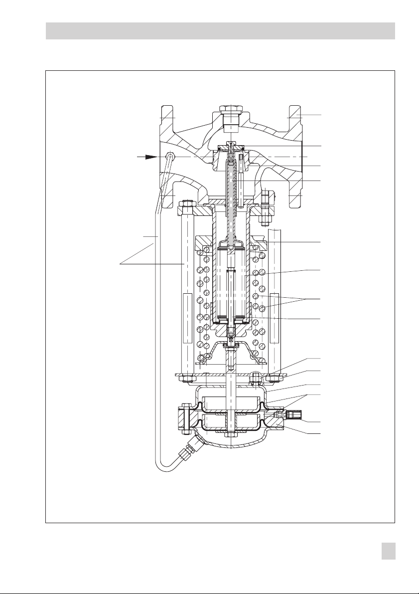
1 Valve body
2 Seat
3 Plug
4 Plug stem
5 Balancing bellows
6 Set point adjuster
7 Positioning springs
8 Bellows
9 Fastening nut
10 Support
11 Actuator housing
11.1 Diaphragms
11.2 Diaphragm rupture
indicator
11.3 Intermediate ring
12 Control line
3
p
2
2
4
6
5
7
8
9
10
11
11.1
11.2
11.3
Fig. 2 · Sectional drawing
EB 2546-2 EN 3
Page 4

Installation
2 Installation
2.1 Position of installation
Note!
Flush the pipeline thoroughly prior to installa
tion of the regulator, ensuring that sealing
particles and other impurities carried along
by the process medium do not impair proper
operation, especially tight shut-off.
Install the excess pressure valve in horizontal
pipelines with the actuator suspended down
wards.
On installing the valve,checkthatthemedium
flows in the same directionasindicatedbythe
arrow on the valve body.
On choosing the point of installation, it is important to make sure that the regulator can
still be easily accessed after completion of the
plant.
The regulator must be installed free ofstress.If
necessary, support the piping near the connecting flanges.
2.2 Shut-off valve, pressure
gauge
Ideally hand-operated shut-off valves should
be installed both upstream and downstream
of the regulator. This allows the plant to be
-
shut down forcleaning and maintenance rou
tines, or when the plant is not operated for
long periods of time.
To monitor the pressuresintheplant,pressure
gauges should be installed upstream and
downstream of the regulator.
-
12 451
1 Shut-off valve
2 Upstream pressure gauge
3 Strainer
4 Pressure reducing valve
5 Downstream pressure gauge
-
Note!
Never attach supports to the valve or actua
tor.
4 EB 2546-2 EN
Fig. 3 · Installation example
-
Page 5

Operation
3 Operation
3.1 Start up
Open the hand-operated shut-off valve
downstream of the excess pressure valve.
Then open slowly the shut-off valve upstream
of the excess pressure valve.
3.2 Set point adjustment
The excess pressure required (upstream pres
) is set by turning the set point adjust
sure p
1
ment (6) with an open-end wrench, up to
DN 50 with flats across width SW 19 and
from DN 65 upwards with SW 22.
Turning it clockwise increases the upstream
pressure and turning it counterclockwise reduces it.
The pressure gauge located on the upstream
pressure side allows the adjusted set point to
be monitored.
4 Troubleshooting
Should the excess pressure (pressure gauge
located on the upstream pressure side) devi
ate significantly from the adjusted set point
value, check first the control line (12) for any
blockages (section 4.1).
If the diaphragms are damaged, the actuator
can be disassembled and the diaphragms
(11.1) can be replaced (section 4.2).
If other causes such as a damaged seat or
plug are found, we recommend that you con
tact our customer service center or return the
regulator to the manufacturer for repair.
Caution!
If the repair is to be performed by the plant
operator, it is important to take into account
when assembling and disassembling the regulator that thevalve springs (7) for valve nominal sizes DN 15to50arepreloadedby up to
70 mm.
To remove the springs, only use a suitable
tool, for example,SAMSON disassembly tool
9129-2747.
Additionally it is important to make sure that
no torque is transmitted to the bellows (8),
otherwise the metal bellows will be irrepara
bly damaged.
Remove the regulator from the pipeline be
fore performing any repair work on it!
-
-
-
-
5 EB 2546-2 EN
Page 6

Troubleshooting
Prior to disassembling the excess
pressure valve, shut down the plant
by slowly closing the shut-off valves.
Relieve the corresponding part of the
plant from pressure and drain it, if
necessary.
4.1 Cleaning the control line
1. Loosen the screw joints connecting the
control line to the actuator and the valve
body, and remove the control line.
2. Blow through the control line to remove
any blockages and clean it. Reattach it to
the actuator and the valve body.
4.2 Replacing the diaphragms
Note!
When the bottom diaphragm fails, the atmospheric pressure in the intermediate chamber
between the diaphragms rises to the level of
the upstream pressure. A red mark becomes
visible in the mechanical rupture indicator.
For versions with an installedpressure switch,
a visual or acoustic signal is triggered.
When the rupture indicator is activated, the
bottom diaphragm must be replaced.
1. Unscrew the control line and clean.
2. Unscrew the nuts (9) on the support (10)
and remove the actuator housing (11).
3. Disassemble the actuator housing andre
place the diaphragm(s).
To reassemble the regulator, proceed in the
reverse order. To start up, proceed as de
scribed in section 3.1.
-
-
EB 2546-2 EN 6
Page 7

Nominal size, set point range and spare parts for actuator
Dimensions and weights
Set point
range
DN 15...25 DN 32...50 DN 65...100
Nominal valve size DN Actuator
bar
Required spring(s)
Order no. 0270-
2 to 4.4
2.4 to 6.6
6 to 11
2166 2167 2166 2167 1410 2203
2166 2168 2166 2199 1410 1417
2200 2201 2200 2201 1416 2204
5 Dimensions and weights
Nominal size
DN
Length L
Height H
Weight
approx. kg
1)
Weights for PN 16,
+10 % for spheroidal graphite iron PN 25 and cast steel PN 40
15 20 25 32 40 50 65 80 100
130 150 160 180 200 230 290 310 350
415 470 600 615
1)
13 14 14.5 20 22 22.5 41.5 48.5 57.5
Diaphragm material
EPDM FKM
Sur
-
Act-
Diaph
Act-
face
cm²
uator
gram
uator
Diaph
gram
Order no.
1070- 0520- 1070- 0520-
80 9500 0868 9508 0869
L
H
ØD 30
EB 2546-2 EN 7
Page 8

6 Customer inquiries
Please submit the following details: (see also
name plate)
Type and nominal size
4
Order number and model number
4
Upstream and downstream pressure
4
Flow rate in m³/h
4
Has a strainer been installed?
4
Installation drawing
4
SAMSON AG · MESS- UND REGELTECHNIK
Weismüllerstraße 3 · 60314 Frankfurt am Main · Germany
Phone: +49 69 4009-0 · Fax: +49 69 4009-1507
Internet: http://www.samson.de
EB 2546-2 EN
S/Z 2007-04
Page 9

Conversion from chromate coating to
iridescent passivation
Conversion from chromate coating to iridescent passivation
We at SAMSON are converting the surface treatment of passivated steel parts in our
production. As a result, you may receive a device assembled from parts that have been subjected to different surface treatment methods. This means that the surfaces of some parts show different reections. Parts can have an iridescent yellow or silver color.
This has no effect on corrosion protection.
For further information, go to u www.samson.de/chrome-en.html
 Loading...