

Page 1
Original instructions
Edition March 2017
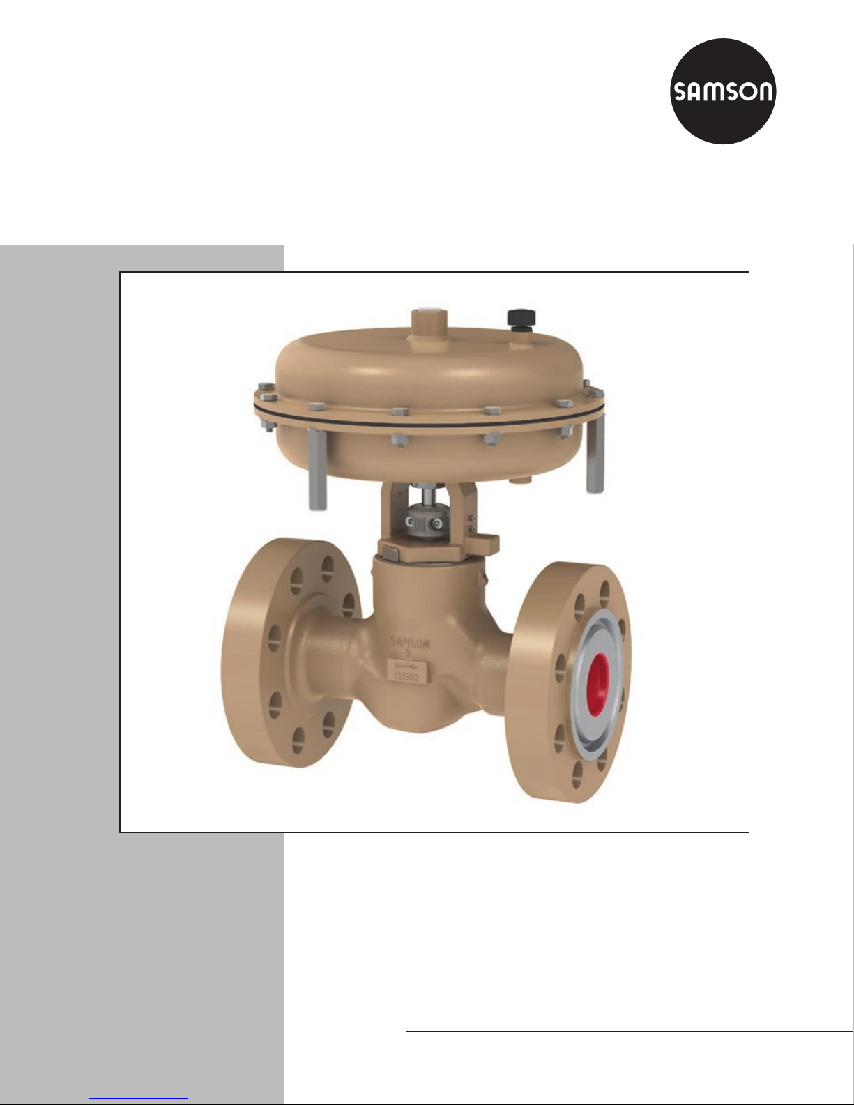
Type3525 Globe Valve
In combination with an actuator
such as SAMSON Type3571 Pneumatic Actuator
ANSI version
Mounting and
Operating Instructions
EB 8823 EN
Page 2
Note on these mounting and operating instructions
These mounting and operating instructions assist you in mounting and operating the device
safely. The instructions are binding for handling SAMSON devices.
Î For the safe and proper use of these instructions, read them carefully and keep them for
future reference.
Î If you have any questions about these instructions, contact SAMSON‘s After-sales Service
Department (samson@samsongroupna.com).
Referenced documentation
The following documents apply in addition to these mounting and operating instructions:
− Mounting and operating instructions for mounted actuator, e.g. uEB8820 for
Type3571 Pneumatic Actuator
− Mounting and operating instructions for mounted valve accessories (e.g. solenoid valve)
The mounting and operating instructions for all supplied devices are included in the delivery.
The latest versions of the documents are available on our website at
uwww.samsoncontrols.com.
Denition of signal words
!
DANGER
Hazardous situations which, if not avoided,
will result in death or serious injury
!
WARNING
Hazardous situations which, if not avoided,
could result in death or serious injury
2 EB 8823 EN
!
NOTICE
Property damage or malfunction
Note
Additional information
Tip
Recommended action
Page 3

Contents
1 Safety instructions and safety measures .........................................................5
1.1 Notes on possible severe personal injury .........................................................7
1.2 Notes on possible personal injury ...................................................................7
1.3 Notes on possible property damage ................................................................9
2 Markings on the control valve ......................................................................10
2.1 Valve nameplate ..........................................................................................10
2.2 Actuator nameplate ......................................................................................11
2.3 Material number ..........................................................................................11
3 Design and principle of operation ................................................................12
3.1 Fail-safe positions ........................................................................................14
3.2 Technical data .............................................................................................15
4 Preparation .................................................................................................20
4.1 Unpacking ..................................................................................................20
4.2 Transporting and lifting ................................................................................20
4.2.1 Transporting ................................................................................................21
4.2.2 Lifting ..........................................................................................................21
4.3 Storage .......................................................................................................23
4.4 Preparation for installation ............................................................................24
5 Mounting and start-up ................................................................................. 26
5.1 Mounting the actuator onto the valve .............................................................26
5.2 Installing the valve into the pipeline ...............................................................26
5.2.1 Checking the installation conditions ...............................................................26
5.2.2 Additional ttings .........................................................................................28
5.2.3 Installing the control valve .............................................................................28
5.3 Quick check ................................................................................................29
6 Operation ...................................................................................................30
6.1 Reversing the ow direction ..........................................................................30
7 Maintenance ...............................................................................................32
7.1 Standard version..........................................................................................33
7.1.1 Replacing the O-rings ..................................................................................33
7.1.2 Replacing the packing ..................................................................................36
7.1.3 Replacing the seat and plug ..........................................................................38
7.1.4 Tools and tightening torques..........................................................................39
EB 8823 EN 3
Page 4

Contents
7.2 Compact version ..........................................................................................40
7.2.1 Replacing the O-rings ..................................................................................40
7.2.2 Replacing the packing ..................................................................................40
7.2.3 Replacing the seat and plug ..........................................................................42
7.2.4 Tools and tightening torques..........................................................................44
7.3 Preparation for return shipment ..................................................................... 44
7.4 Ordering spare parts and operating supplies .................................................45
8 Malfunctions ...............................................................................................46
8.1 Troubleshooting ...........................................................................................46
8.2 Emergency action ........................................................................................47
9 Decommissioning and disassembly ..............................................................48
9.1 Decommissioning .........................................................................................48
9.2 Removing the valve from the pipeline .............................................................48
9.3 Removing the actuator from the valve ............................................................49
9.4 Disposal ......................................................................................................49
10 Appendix ....................................................................................................50
10.1 Customer inquiries .......................................................................................50
10.2 Certicates ..................................................................................................50
10.3 Spare parts .................................................................................................52
4 EB 8823 EN
Page 5

Safety instructions and safety measures
1 Safety instructions and safety measures
Intended use
The SAMSON Type3525 Globe Valve in combination with an actuator (e.g. Type3571
Pneumatic Actuator) is designed to regulate the ow rate, pressure or temperature of liquids,
gases or vapors. The valve is designed for use in high-pressure on/off applications in up-
stream and midstream oil and gas production.
The valve with its actuator is designed to operate under exactly dened conditions (e.g. oper-
ating pressure, process medium, temperature). Therefore, operators must ensure that the control valve is only used in applications that meet the specications used for sizing the valve at
the ordering stage. In case operators intend to use the control valve in other applications or
conditions than specied, SAMSON must be contacted.
SAMSON does not assume any liability for damage resulting from the failure to use the
valve for its intended purpose or for damage caused by external forces or any other external
factors.
Î Refer to the technical data and nameplate for limits and elds of application as well as
possible uses.
Reasonably foreseeable misuse
The control valve is not suitable for the following applications:
− Use outside the limits dened during sizing and in the technical data
− Use outside the limits dened by the valve accessories mounted on the control valve
Furthermore, the following activities do not comply with the intended use:
− Use of non-original spare parts
− Performing service and repair work not described in these instructions
Qualications of operating personnel
The control valve must be mounted, started up, serviced and repaired by fully trained and
qualied personnel only; the accepted industry codes and practices are to be observed. Ac-
cording to these mounting and operating instructions, trained personnel refers to individuals
who are able to judge the work they are assigned to and recognize possible hazards due to
their specialized training, their knowledge and experience as well as their knowledge of the
applicable standards.
EB 8823 EN 5
Page 6

Safety instructions and safety measures
Personal protective equipment
We recommend wearing the following protective equipment depending on the process medi-
um:
− Protective clothing, gloves and eyewear in applications with hot, cold and/or corrosive
media when working near or on the valve
− Hearing protection when working near the valve
Î Check with the plant operator for details on further protective equipment.
Revisions and other modications
Revisions, conversions or other modications to the product are not authorized by SAMSON.
They are performed at the user‘s own risk and may lead to safety hazards. Furthermore, the
control valve may no longer meet the requirements for its intended use.
Safety devices
Upon supply air or control signal failure, the valve moves to its fail-safe position (see section3.1). The fail-safe action of the actuator is the same as its direction of action and is specied on the nameplate of SAMSON actuators (see actuator documentation).
Warning against residual hazards
To avoid personal injury or property damage, plant operators and operating personnel must
prevent hazards that could be caused in the control valve by the process medium, the operating pressure, the signal pressure or by moving parts by taking appropriate precautions. They
must observe all hazard statements, warning and caution notes in these mounting and operating instructions, especially for installation, start-up and maintenance.
Responsibilities of the operator
The operator is responsible for proper operation and compliance with the safety regulations.
Operators are obliged to provide these mounting and operating instructions to the operating
personnel and to instruct them in proper operation. Furthermore, operators must ensure that
operating personnel or third persons are not exposed to any danger.
Responsibilities of operating personnel
Operating personnel must read and understand these mounting and operating instructions as
well as the specied hazard statements, warning and caution notes. Furthermore, the operat-
ing personnel must be familiar with the applicable health, safety and accident prevention
regulations and comply with them.
6 EB 8823 EN
Page 7

Safety instructions and safety measures
Referenced standards and regulations
The SAMSON Type3525 Globe Valve complies with the requirements of ASMEB16.34.
1.1 Notes on possible severe personal injury
!
DANGER
Risk of bursting in pressure equipment.
Control valves and pipelines are pressure equipment. Improper opening can lead to
valve components bursting.
Î Before starting any work on the control valve, depressurize all plant sections con-
cerned and the valve.
Î Drain the process medium from all the plant sections concerned as well as the valve.
Î Wear personal protective equipment.
1.2 Notes on possible personal injury
!
WARNING
Crush hazard arising from moving parts.
The control valve contains moving parts (actuator and plug stems), which can injure
hands or ngers if inserted into the valve.
Î Do not insert hands or ngers into the yoke while the valve is in operation.
Î While working on the control valve, disconnect and lock the pneumatic air supply as
well as the control signal.
Risk of personal injury when actuator vents.
While the valve is operating, the actuator may vent during closed-loop control or when
the valve opens or closes.
Î Install the control valve in such a way that the actuator does not vent at eye level.
Î Use suitable vent plugs.
Î Wear eye protection when working in close proximity to the control valve.
EB 8823 EN 7
Page 8

Safety instructions and safety measures
!
WARNING
Risk of personal injury due to sudden escape of process medium.
The valve has a safety bleed to detect damaged or worn O-rings. The process medium
may escape suddenly and at high pressure.
Î Wear protective clothing, gloves and eyewear when working near or on the valve.
Î Do not stay in the range of the safety bleed longer than necessary.
Risk of personal injury due to residual process medium in the valve.
While working on the valve, residual process medium can escape and, depending on its
properties, may lead to personal injury, e.g. (chemical) burns.
Î If possible, drain the process medium from all the plant sections concerned and the
valve.
Î Wear protective clothing, gloves and eyewear.
Risk of burn injuries due to hot or cold components and pipelines.
Depending on the process medium, valve components and pipelines may get very hot or
cold and cause burn injuries.
Î Allow components and pipelines to cool down or heat up.
Î Wear protective clothing and gloves.
Risk of personal injury due to preloaded springs.
Valves in combination with pneumatic actuators with preloaded springs are under tension. These control valves with SAMSON pneumatic actuators can be identied by the
long bolts protruding from the bottom of the actuator.
Î Before starting any work on the actuator, relieve the compression from the preloaded
springs (see associated actuator documentation).
8 EB 8823 EN
Page 9

Safety instructions and safety measures
1.3 Notes on possible property damage
!
NOTICE
Risk of valve damage due to contamination (e.g. solid particles) in the pipeline.
The plant operator is responsible for cleaning the pipelines.
Î Flush the pipelines before start-up.
Î Observe the maximum permissible pressure for both the valve and plant.
Risk of valve damage due to unsuitable medium properties.
The valve is designed for a process medium with dened properties.
Î Only use the process medium specied for sizing the valve.
Risk of leakage and valve damage due to excessively high or low tightening torques.
Excessively tightened torques lead to parts wearing out quicker. Parts that are too loose
may cause leakage.
Î Observe the specied tightening torques (see Table5 and Table6).
Risk of valve damage due to the use of unsuitable lubricants.
The lubricants to be used depend on the valve material. Unsuitable lubricants may cor-
rode and damage the valve surface.
Î Only use lubricants approved by SAMSON (see parts list).
EB 8823 EN 9
Page 10
Markings on the control valve
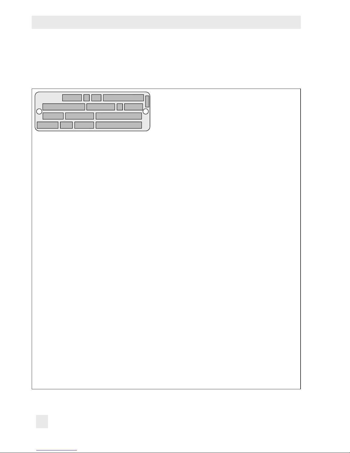
2 Markings on the control valve
2.1 Valve nameplate
18
12
17
5
6
9
USA
Made in
SAMSON
10
13
7
14
2
15 16
11
3
4
8
2 Type designation
3 Type version
C: compact · S: standard
4 –
5 Material
6 Year of manufacture
7 Order number with modication index
8 Item in order
9 Conformity
10 Nominal size (NPS)
11 Pressure rating (Cl.)
12 For Intermediate Rating Standard Class: pressure and lower temperature limit
For other pressure ratings: lower temperature limit
13 Flow coefcient
14 Characteristic:
%: equal percentage · Lin: linear
15 Seat/plug sealing:
ME: metal
ST: metal base material stellited
®
or base material pure Stellite
®
TC: tungsten carbide
16 Option code for trim identication (stem, plug, seat)
17 For Intermediate Rating Standard Class: pressure and upper temperature limit
For other pressure ratings: upper temperature limit
18 Not used
Fig.1: Type3525 nameplate
10 EB 8823 EN
Page 11
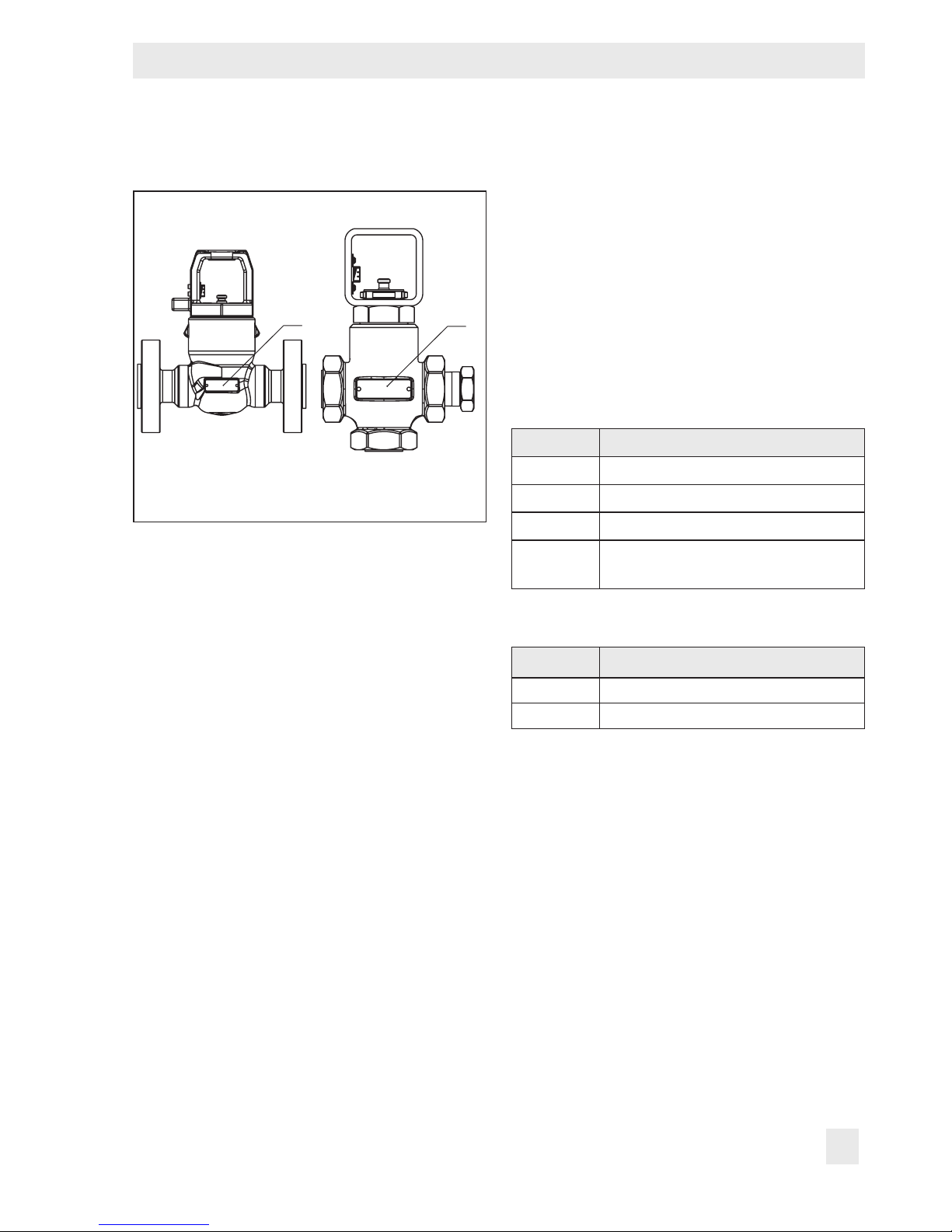
Markings on the control valve
The valve nameplate is afxed to the rear of
the body.
80
Fig.2: Nameplate at the body
80
2.2 Actuator nameplate
2.3 Material number
The seat and plug of the valves have an article number written on them. Specifying this
article number, you can contact us to nd out
which material is used. Additionally, a seat
code is used to identify the trim material.
This seat code is specied on the nameplate
(seat/plug seal, 13). For more details on the
nameplate, see section2.1.
Standard version
Seat code Material
10 A351CF3M
11 Stellite
12 A747 CB7Cu1 H1150 DBL
14
®
6
WC/TC (HW-Co)/A747 CB7Cu1
H1150DBL
See associated actuator documentation.
Compact version
Seat code Material
11 Stellite
13 WC/TC (HW-Co)/A479 XM-19-H
®
6
EB 8823 EN 11
Page 12

Design and principle of operation
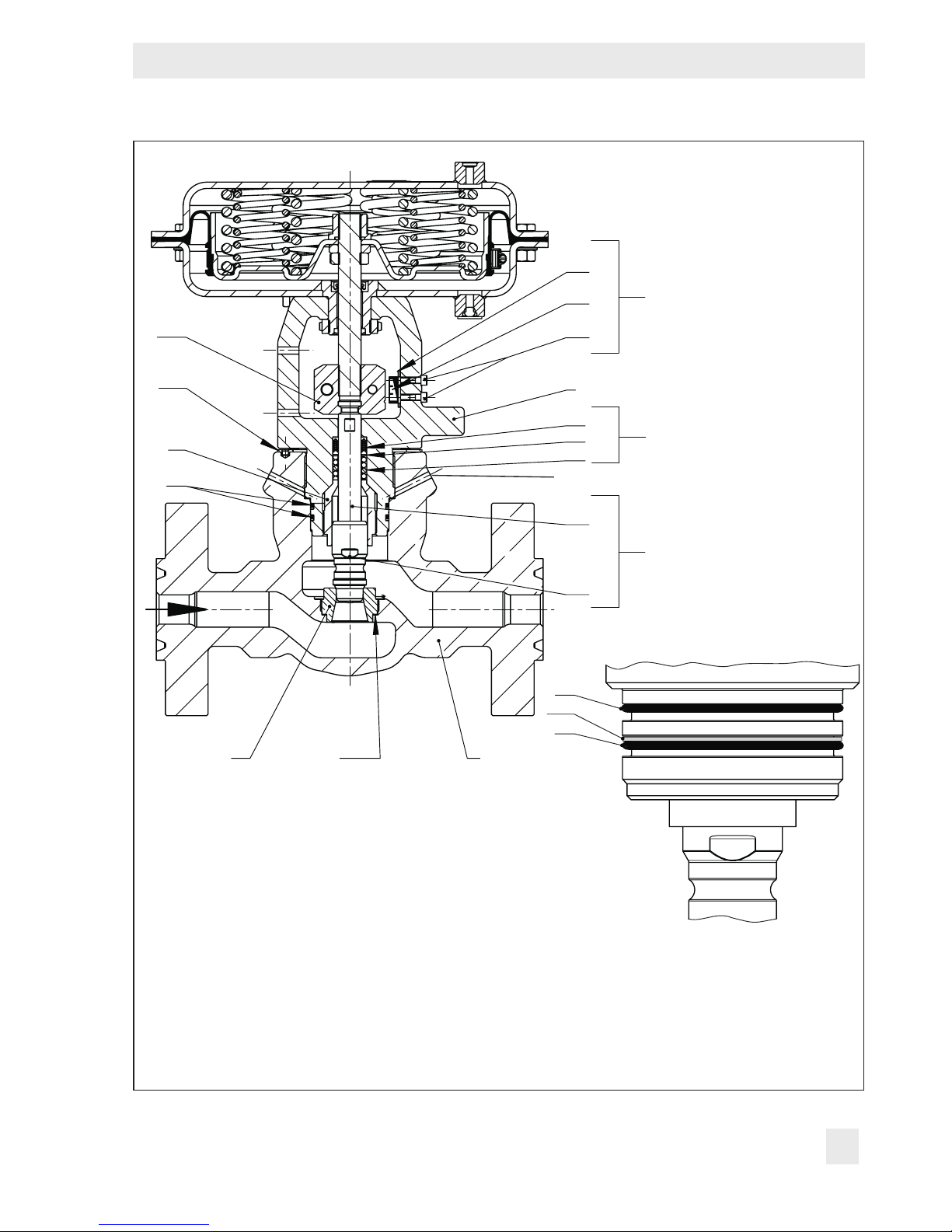
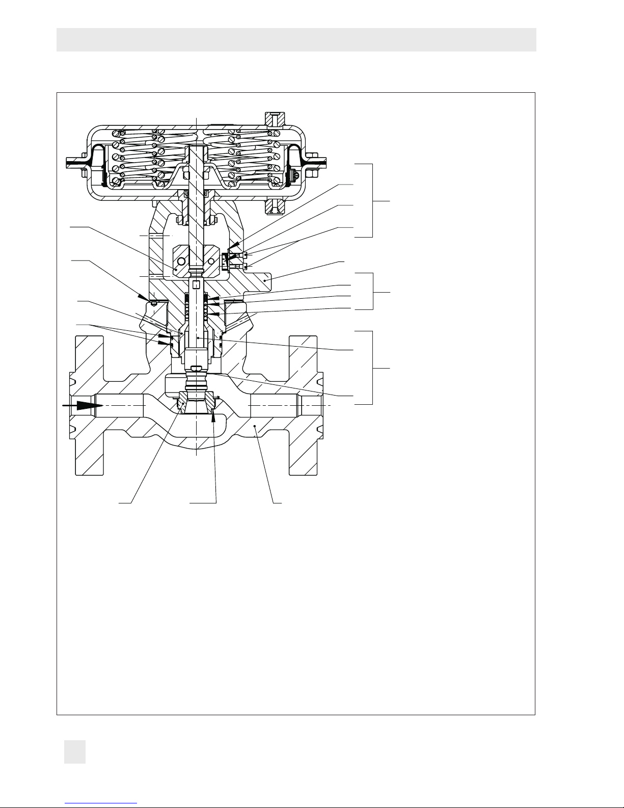
3 Design and principle of oper-
ation
The single-seated Type3525 Globe Valve is
combined with a SAMSON Type3571
Pneumatic Actuator (see Fig.4).
The seat (4) and plug with plug stem (5) are
assembled in the body (1). The plug stem is
connected to the actuator stem (A7) by the
stem connector clamps (A26) and is sealed
by a spring-loaded V-ring packing (16). The
springs in the pneumatic actuator (A) are located either above or below the diaphragm
depending on the selected fail-safe action
(see section3.1). A change in the signal
pressure acting on the diaphragm causes the
plug to move. The actuator size is determined by the diaphragm area.
The medium ows through the valve in the
direction indicated by the arrow. The standard valve body version normally operates
in the ow-to-open direction (FTO). The medium ows across the plug from bottom to
top. The compact valve body versions normally operate in the ow-to-close direction
(FTC). The medium ows across the plug
from top to bottom.
The valves have a safety bleed to detect
damaged or worn O-rings.
A rise in signal pressure causes the force acting on the diaphragm in the actuator to in-
crease. The springs are compressed. De-
pending on the selected direction of action,
the actuator stem retracts or extends. As a
result, the plug position in the seat changes
and determines the ow rate through the
valve.
There are three versions available:
− Standard globe valve with anges (see
Fig.3) or threaded ends
− Compact globe valve with threaded ends
− Compact T-pattern valve with threaded
ends (see Fig.5)
Standard globe valves >Class900 with FKM
O-ring are equipped with an additional support ring (244) which is inserted into the
groove of the bottom O-ring (17).
Compact T-pattern valves are equipped with
a screw plug (112). The screw plug can be
positioned either at the bottom outlet or –
depending on the ow direction – at the side
outlet. It must not be positioned at the inlet.
Actuators
In these instructions, the combination with a
Type3571 Pneumatic Actuator is described.
The pneumatic actuator for the standard version can be replaced by another Type3571
Pneumatic Actuator in a different size, but
with the same travel.
Î Observe the maximum permissible actu-
ator force.
Note
If the travel range of the actuator is larger
than the travel range of the valve, the spring
assembly in the actuator must be preloaded
so that the travel ranges match. See associated actuator documentation.
12 EB 8823 EN
Page 13
Design and principle of operation
244
Fig.3: Standard version
Type3525 Globe
Valve with Type3571
Pneumatic Actuator
83
84
60
A28
224
7
17
82
2
16
12
15
11
Safety bleed
36
5
29
17
17
4
127
1
1 Body
2 Bonnet
4 Seat
5 Plug (29, 36)
7 Guide bushing
11 Spring
12 Washer
15 Packing (11, 12, 16)
16 V-ring packing
17 O-ring
29 Plug head
EB 8823 EN 13
36 Plug stem
60 Yoke assembly with
travel indicator
(82, 83, 84)
82 Screw
83 Hanger
84 Travel indicator scale
127 Seat ring gasket
224 Tab washer
244 Support ring
A7 Actuator stem
A28 Stem connector clamp
Fig.4: Bonnet for standard
version >Class900
with FKM O-ring
Page 14
Design and principle of operation
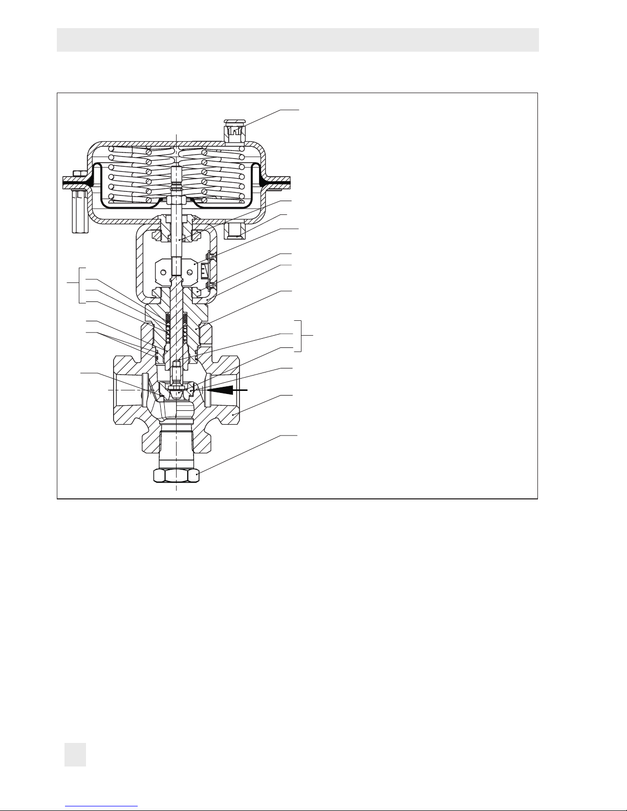
A16
16
15
12
11
7
17
127
A7
S
A28
92
3
2
36
29
4
1
112
1 Body
2 Bonnet
3 Yoke
4 Seat
5 Plug (29, 36)
7 Guide bushing
11 Spring
12 Washer
15 Packing (11, 12, 16)
16 V-ring packing
17 O-ring
29 Plug head
36 Plug stem
92 Lock nut
5
112 Screw plug
127 Seat ring gasket
A7 Actuator stem
A16 Vent plug
A28 Stem connector clamp
S Signal pressure connection
3.1 Fail-safe positions
The fail-safe position depends on the actua-
tor used.
Depending on how the compression springs
are arranged in the pneumatic actuator, the
valve has two different fail-safe positions:
Actuator stem extends
When the signal pressure is reduced or the
air supply fails, the springs move the actuator stem downward and close the valve. The
valve opens when the signal pressure is in-
Fig.5: Compact version Type3525
T-pattern Valve with Type3571
Pneumatic Actuator
creased enough to overcome the force exerted by the springs.
Actuator stem retracts
When the signal pressure is reduced or the
air supply fails, the springs move the actuator stem upwards and open the valve. The
valve closes when the signal pressure is increased enough to overcome the force exerted by the springs.
14 EB 8823 EN
Page 15
Design and principle of operation
3.2 Technical data
The nameplates on the valve and actuator
provide information on the control valve ver-
sion. See section2.1 and the actuator docu-
mentation.
Note
More information is available in Data Sheet
uT8823.
Temperature range
The valve version with an HNBR O-ring is
designed for a temperature range from –50
to +300°F (–46 to +149°C). By using an
FKM O-ring the temperature range can be
extended to –10 to +400°F (–23 to
+204°C). In case of oils that cause severe
swelling an FKM O-ring is to be used.
!
WARNING
Risk of hearing loss or deafness due to loud
noise.
Wear hearing protection when working near
the valve.
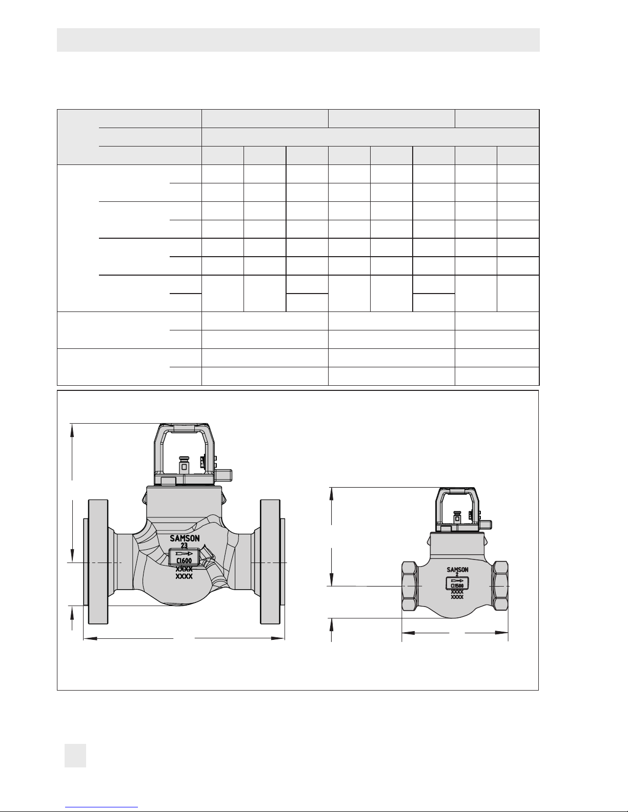
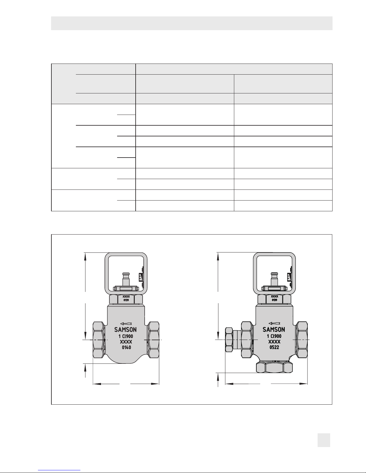
Dimensions and weights
Table1 and Table2 provide a summary of
the dimensions and weights of the standard
and compact version of Type3525 Valve.
The lengths and heights are shown in the dimensional drawings on p.16 (standard
version) and p.17 (compact version).
Leakage class
The leakage class according to ANSI/
FCI70-2 is IV for all sealing materials of the
seat/plug sealing (see pos. 12 on nameplate: ME, ST, TC).
Noise emission
SAMSON is unable to make general state-
ments about noise emission as it depends on
the valve version, plant facilities and process
medium. On request, SAMSON can perform
calculations according to IEC60534,
Part8-3 and Part8-4 or VDMA24422 (edition89).
EB 8823 EN 15
Page 16
Design and principle of operation
L
H2
H1
H2
H1
Table1: Dimensions of Type3525 Valve · standard version
NPS 1 2 3
Body
type
Version Standard globe valve
Connection RF RJF NPT RF RJF NPT RF RJF
Class600
Class900
L
Class1500
Class1700
H1
H2
Dimensional drawings
in 8.27 8.27 – 11.26 11.38 9.06 13.27 13.39
mm 210 210 – 286 289 230 337 340
in 10.75 10.75 6.26 13.39 13.50 9.06 15.24 15.35
mm 273 273 159 340 343 230 387 390
in 10.75 10.75 6.10 13.39 13.50 9.06 15.98 16.10
mm 273 273 155 340 343 230 406 409
in
– –
mm 155 230
in 8.70 9.21 9.21
mm 221 234 234
in 1.85 2.95 2.95
mm 47 75 75
6.10
– –
9.06
– –
Standard globe valve, NPS1 to 3, anges Standard globe valve, NPS1 to 2,
16 EB 8823 EN
L
threaded ends
Page 17
Design and principle of operation
L
H2
H1
L
H2
H1
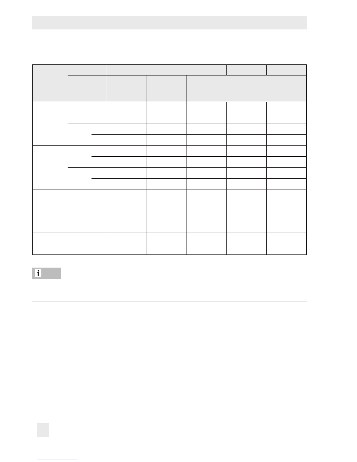
Table2: Dimensions of Type3525 Valve · compact versions
NPS 1
Body
type
Version
Compact
globe valve
Compact
T-pattern valve
Connection NPT NPT
in
Class600
– –
mm
L
Class900
mm 119 119
in 4.69 4.69
Class1500
Class1700
in
– –
mm
1)
1)
in 6.18 6.18
H1
mm 157 157
H2
in 1.69 2.36
mm 43 60
1)
Length without threaded stopper. This length can be extended by approx. 1.14 in/29mm depend-
1)
1)
ing on the position of the threaded stopper.
Dimensional drawings
Compact globe valve, NPS1 Compact T-pattern valve, NPS1
EB 8823 EN 17
Page 18
Design and principle of operation
Table3: Weights for Type3525 Valve
NPS 1 2 3
Body type
RF/RTJ
Class600
NPT
RF/RTJ
Class900
NPT
RF/RTJ
Class1500
NPT
Class1700 NPT
Version
Compact
globe valve
lbs – – 34.4 60.6 83.8
kg – – 15.6 27.5 38
lbs – – – 44.1 –
kg – – – 20 –
lbs – – 45.2 90.4/91.5 108.0
kg – – 20.5 41/41.5 49
lbs 9.5 11.0 27.6 44.1 –
kg 4.3 5 12.5 20 –
lbs – – 45.2 90.4/91.5 135.6
kg – – 20.5 41/41.5 61.5
lbs – – 27.6 44.1 –
kg – – 12.5 20 –
lbs – – 27.6 44.1 –
kg – – 12.5 20 –
Compact
T-pattern
valve
Standard globe valve
Note
Refer to the following data sheets for more dimensions and weights:
uT8820 for Type3571 Pneumatic Actuator
18 EB 8823 EN
Page 19

EB 8823 EN 19
Page 20
Preparation
4 Preparation
After receiving the shipment, proceed as follows:
1. Check the scope of delivery. Compare
the shipment received against the delivery note.
2. Check the shipment for transportation
damage. Report any damage to
SAMSON and the forwarding agent (refer to delivery note).
4.1 Unpacking
Note
Do not remove the packaging until immediately before installing the valve into the pipeline.
4.2 Transporting and lifting
!
DANGER
Hazard due to suspended loads falling.
Stay clear of suspended or moving loads.
!
WARNING
Risk of lifting equipment tipping and risk of
damage to lifting accessories due to exceeding the rated lifting capacity.
− Only use approved lifting equipment and
accessories whose minimum lifting capacity is higher than the weight of the valve
(including actuator, if applicable).
− Refer to section3.2 or Data Sheet
uT8823 for weights.
Proceed as follows to lift and install the
valve:
1. Remove the packaging from the valve.
2. Dispose of the packaging in accordance
with the valid regulations.
!
NOTICE
Risk of valve damage due to foreign particles entering the valve.
The protective caps tted on the valve’s inlet
and outlet prevent foreign particles from entering the valve and damaging it.
Do not remove the protective caps until immediately before installing the valve into the
pipeline.
!
WARNING
Risk of personal injury due to control valve
tipping.
− Observe the valve’s center of gravity.
− Secure the valve against tipping over or
turning.
20 EB 8823 EN
Page 21

Preparation
!
NOTICE
Risk of valve damage due to incorrectly attached slings.
The welded-on lifting eyelet on SAMSON
actuators (116in²/750cm²) is only intended
for mounting and removing the actuator as
well as lifting the actuator without valve. Do
not use this lifting eyelet to lift the entire control valve assembly.
− When lifting the control valve, make sure
that the slings attached to the valve body
and to the additional lifting eyelet bear the
entire load.
− Do not attach load-bearing slings to the
actuator, handwheel or any other parts.
− Observe lifting instructions (see sec-
tion4.2.2.
Tip
4.2.1 Transporting
The control valve can be transported using
lifting equipment (e.g. crane or forklift).
Î Leave the control valve in its transport
container or on the pallet to transport it.
Î Observe the transport instructions.
Transport instructions
− Protect the control valve against external
inuences (e.g. impact).
− Do not damage the corrosion protection
(paint, surface coatings). Remove any
damage immediately.
− Protect the control valve against moisture
and dirt.
− The permissible transportation tempera-
ture of standard control valves is –4 to
+149°F (–20 to +65°C).
SAMSON’s After-sales Service department
can provide more detailed transport and lifting instructions on request.
Note
Contact SAMSON’s After-sales Service department for the transportation temperatures
of other valve versions.
4.2.2 Lifting
To install a large valve into the pipeline, use
lifting equipment (e.g. crane or forklift) to lift
it.
Lifting instructions
− Secure slings against slipping.
− Make sure the slings can be removed
from the valve once it has been installed
into the pipeline.
EB 8823 EN 21
Page 22

Preparation
− Prevent the control valve from tilting or
tipping.
− Do not leave loads suspended when in-
terrupting work for longer periods of
time.
− Make sure that the axis of the pipeline is
always horizontal during lifting and the
axis of the plug stem is always vertical.
− Make sure that the additional sling be-
tween the liftling eyelet and rigging
equipment (hook, shackle etc.) does not
bear any load when lifting control valves
with 116in² (750cm²) actuators. The
sling only protects the control valve from
tilting while being lifted. Before lifting the
control valve, tighten the sling.
Version with anges or threaded ends
1. Attach one sling to each ange or
threaded end of the body and to the rigging equipment (e.g. hook) of the crane
or forklift (see Fig.6).
2. Actuator with 116in² (750cm²) actua-
tor area: Attach another sling to the lifting eyelet on the actuator and to the rig-
ging equipment.
3. Version with threaded ends: Secure the
slings attached to the body against slipping using a connector.
Fig.6: Lifting points on the control valve
22 EB 8823 EN
Page 23

4. Carefully lift the control valve. Check
whether the lifting equipment and acces-
sories can bear the weight.
5. Move the control valve at an even pace
to the site of installation.
Preparation
Note
We recommend regularly checking the control valve and the prevailing storage conditions during long storage times.
6. Install the valve into the pipeline (see section5.2).
7. Version with anges: Check whether the
anges are bolted tight and the valve in
the pipeline holds.
Version with threaded ends: Check
whether the threaded connection is tight
and the valve in the pipeline holds.
Check whether an appropriate sealing is
installed.
8. Remove slings and, if applicable, con-
nector.
Tip
We recommend using a hook with safety
latch (see Fig.6). The safety latch prevents
the slings from slipping during lifting and
transporting.
Storage instructions
− Protect the control valve against external
inuences (e.g. impact).
− Do not damage the corrosion protection
(paint, surface coatings). Remove any
damage immediately.
− Protect the control valve against moisture
and dirt. Store it at a relative humidity of
less than 75%. In damp spaces, prevent
condensation. If necessary, use a drying
agent or heating.
− Make sure that the ambient air is free of
acids or other corrosive media.
− The permissible storage temperature of
standard control valves is –4 to +149°F
(–20 to +65°C).
Note
4.3 Storage
!
NOTICE
Risk of valve damage due to improper storage.
− Observe storage instructions.
− Avoid long storage times.
− Contact SAMSON in case of different stor-
age conditions or longer storage times.
EB 8823 EN 23
Contact SAMSON’s After-sales Service department for the storage temperatures of other valve versions.
− Do not place any objects on the control
valve.
Page 24

Preparation
Special storage instructions for soft parts
Soft parts, e.g. actuator diaphragm
− To keep soft parts in shape and to pre-
vent cracking, do not bend them or hang
them up.
− We recommend a storage temperature of
59°F (15°C) for soft parts.
− Store soft parts away from lubricants,
chemicals, solutions and fuels.
Tip
SAMSON’s After-sales Service department
can provide more detailed storage instructions on request.
4.4 Preparation for installation
Î For steam applications, make sure that
the pipelines are dry. Moisture will damage the inside of the valve.
Î Check any mounted pressure gauges to
make sure they function.
Î When the valve and actuator are al-
ready assembled, check the tightening
torques at the bonnet. Components may
loosen during transport.
Proceed as follows:
Î Flush the pipelines.
Note
The plant operator is responsible for cleaning the pipelines. Observe the maximum
permissible pressure for both the valve and
plant.
Î Check the valve to make sure it is clean.
Î Check the valve for damage.
Î Check to make sure that the type desig-
nation, valve size, material, pressure rating and temperature range of the valve
match the plant conditions (size and
pressure rating of the pipeline, medium
temperature etc.).
24 EB 8823 EN
Page 25

EB 8823 EN 25
Page 26

Mounting and start-up
5 Mounting and start-up
SAMSON valves are delivered ready for
use. In special cases, the valve and actuator
are delivered separately and must be assembled on site. The procedure to mount and
start up the valve are described in the following.
!
NOTICE
Risk of valve damage due to excessively high
or low tightening torques.
Excessively tightened torques lead to parts
wearing out quicker. Parts that are too loose
may cause leakage.
Observe the specied tightening torques (see
Table5 and Table6).
5.1 Mounting the actuator onto
the valve
Proceed as described in the actuator docu-
mentation if the valve and actuator have not
been assembled by SAMSON:
5.2 Installing the valve into the
pipeline
5.2.1 Checking the installation
conditions
Pipeline routing
The inlet and outlet lengths vary depending
on the process medium. To ensure the control
valve functions properly, follow the installation instructions given below:
Î Observe the inlet and outlet lengths (see
Table4). Contact SAMSON if the valve
conditions or states of the medium process deviate.
Î Install the valve free of stress and with the
least amount of vibrations as possible. If
necessary, attach supports to the valve.
Î Install the valve allowing sufcient space
to remove the actuator and valve or to
perform service and repair work on
them.
Mounting position
Note
− Remove the mounted actuator before
mounting the other actuator (see associated actuator documentation).
− Preloading the actuator springs increases
the thrust of a pneumatic actuator and reduces the travel range of the actuator (see
associated actuator documentation).
26 EB 8823 EN
Generally, we recommend installing the
valve with the actuator upright and on top of
the valve.
Î Contact SAMSON for alternative mount-
ing positions.
Support or suspension
Depending on the valve version and mount-
ing position, the control valve and pipeline
must be supported or suspended. The plant
engineering company is responsible in this
case.
Page 27
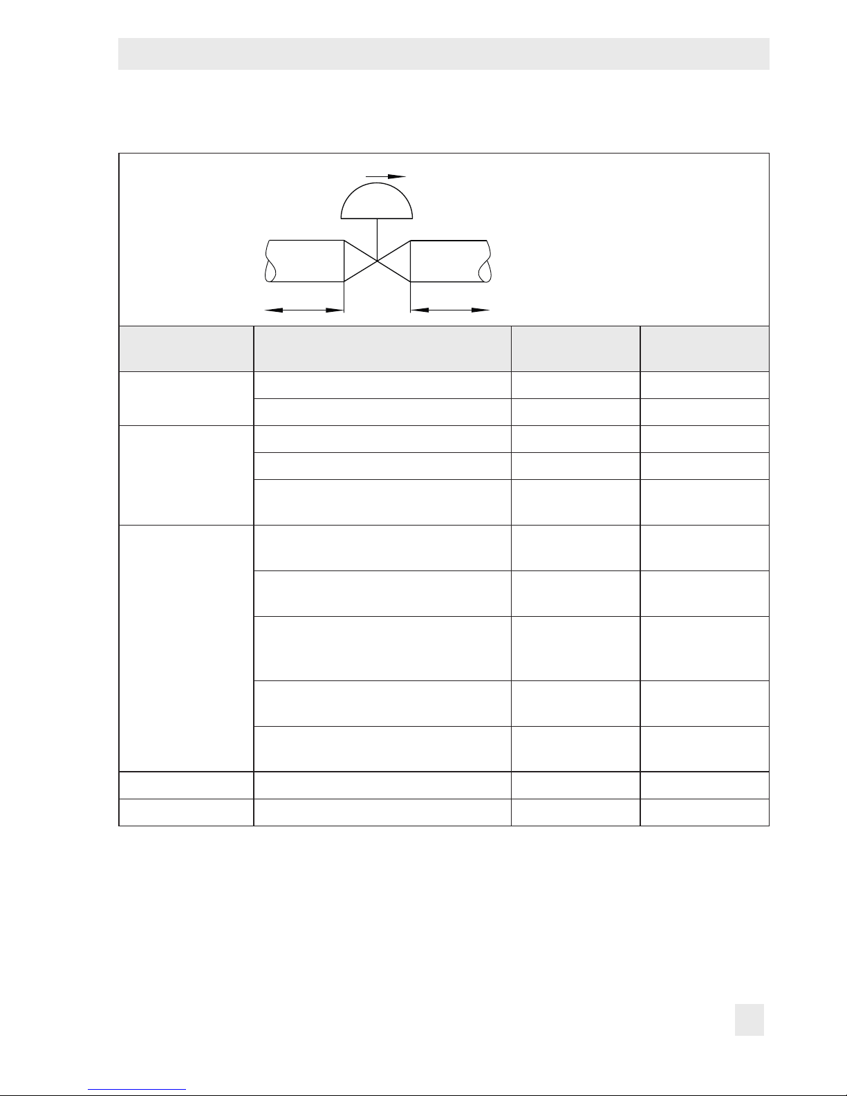
Table4: Inlet and outlet lengths
Q
a x NPS b x NPS
Mounting and start-up
Q Flow rate
a Inlet length
b Outlet length
State of process
medium
Gas
Vapor
Liquid
Valve conditions Inlet length a Outlet length b
Ma≤0.3 2 4
0.3≤Ma≤0.7 2 10
Ma≤0.3
0.3≤Ma≤0.7
1)
1)
Saturated steam (percentage of condensate >5%)
Free of cavitation/w<33ft/s
(w<10m/s)
Cavitation producing
noise/w≤10ft/s (w≤3m/s)
2 4
2 10
2 20
2 4
2 4
Cavitation producing
noise/10<w<16ft/s
2 10
(3<w<5m/s)
Critical cavitation/w≤10ft/s
(w≤3m/s)
Critical cavitation/10<w16ft/s
(3<w<5m/s)
2 10
2 20
Flashing – 2 20
Multi-phase – 10 20
EB 8823 EN 27
Page 28

Mounting and start-up
!
NOTICE
Premature wear and leakage due to insufcient support or suspension.
Attach a suitable support or suspension on
the valve, if necessary.
Vent plugs
Vent plugs are screwed into the exhaust air
ports of pneumatic, electropneumatic and
electric devices. They ensure that any exhaust air that forms can be vented to the atmosphere (to avoid excess pressure in the
device). Furthermore, the vent plugs allow
air intake to prevent a vacuum from forming
in the device.
Î Locate the vent plug on the opposite side
to the workplace of operating personnel.
Î On mounting valve accessories, make
sure that they can be operated from the
workplace of the operating personnel.
Note
The workplace of operating personnel is the
location from which the valve, actuator and
any mounted valve accessories can be accessed to operate them.
Insulation
Do not insulate valves mounted to comply
with NACE MR0175 requirements.
Note
Contact SAMSON’s After-sales Service department in case that an insulation is required.
5.2.3 Installing the control
valve
Version with anges
1. Depressurize the plant and interrupt the
medium ow while the valve is being in-
stalled.
2. Remove the protective caps from the
valve ports before installing the valve.
3. Lift the valve using suitable lifting equip-
ment to the site of installation (see section4.2.2). Observe the ow direction
through the valve. The arrow on the
valve indicates the direction of ow.
4. Make sure that the correct ange gaskets
are used.
5. Bolt the pipe to the valve free of stress.
5.2.2 Additional ttings
Strainer
For certain applications an additional strain-
er can be installed in order to reduce excessive wear.
28 EB 8823 EN
6. Depending on the eld of application,
allow the valve to cool down or heat up
to reach ambient temperature before
start up.
7. Slowly resume medium ow in the pipe-
line after the valve has been installed.
Page 29
Mounting and start-up
!
NOTICE
Risk of valve damage due to a sudden pressure increase and resulting high ow velocities.
Slowly resume medium ow during start-up.
8. Check the valve to ensure it functions
properly.
Version with threaded ends
1. Proceed as described for Version with
anges (steps 1 to 3).
2. Screw the valve onto the pipeline. Install
an appropriate sealing. Make sure that
the valve is free of stress.
T-pattern: Screw the screw plug into the
desired outlet. The screw plug, too, needs
to be installed with an appropriate sealing.
3. Proceed as described for Version with
anges (steps 6 to 8).
5.3 Quick check
SAMSON valves are delivered ready for
use. To test the valve’s ability to function, the
following quick checks can be performed:
Slowly resume medium ow during start-up.
3. Check the valve for leakage to the atmo-
sphere (visual inspection).
Travel motion
The movement of the actuator stem must be
linear and smooth.
Î Open and close the valve, observing the
movement of the actuator stem.
Î Apply the maximum and minimum con-
trol signals to check the end positions of
the valve.
Î Check the travel reading at the travel in-
dicator scale.
Fail-safe position
Î Shut off the signal pressure line.
Î Check whether the valve moves to the
fail-safe position.
Pressure testing
When pressure testing make sure that the fol-
lowing conditions are met:
− Retract the plug to open the valve.
− Observe the maximum permissible pres-
sure for both the valve and plant.
Tight shut-off
1. Close the valve.
2. Slowly resume medium ow in the pipe-
line.
!
NOTICE
Risk of valve damage due to a sudden pressure increase and resulting high ow velocities.
EB 8823 EN 29
Note
The plant operator is responsible for pressure
testing. SAMSON’s After-sales Service department can support you in planning and
implementing the pressure test for your plant.
Page 30
Operation
6 Operation
Immediately after completing mounting and
start-up (see section5), the valve is ready for
use.
!
WARNING
Crush hazard arising from moving parts (actuator and plug stem).
Do not insert hands or nger into the yoke
while the valve is in operation.
!
WARNING
Risk of personal injury when the actuator
vents.
Wear eye protection when working in close
proximity to the control valve.
!
WARNING
Risk of personal injury due to sudden escape
of process medium.
The valve has a safety bleed to detect damaged or worn O-rings. The process medium
may escape suddenly and at high pressure.
− Wear protective clothing, gloves and eye-
wear when working near or on the valve.
− Do not stay in the range of the safety bleed
longer than necessary.
6.1 Reversing the ow
direction
The medium ows through the valve in the
direction indicated by the arrow. The standard valve body version normally operates
in the ow-to-open direction (FTO). The medium ows across the plug from bottom to
top. The compact valve body versions normally operate in the ow-to-close direction
(FTC). The medium ows across the plug
from top to bottom.
The ow direction can be reversed from FTO
to FTC and vice versa.
!
NOTICE
Risk of valve damage due to altered forces.
When reversing the ow direction, altered
forces occur which may damage the valve if
incorrectly calculated.
To reverse the ow direction, contact
SAMSON’s After-sales Service department.
!
NOTICE
Operating disturbed by a blocked actuator
and plug stem.
Do not impede the movement of the actuator
or plug stem by inserting objects into their
path.
30 EB 8823 EN
Page 31

EB 8823 EN 31
Page 32
Maintenance
7 Maintenance
The control valve is subject to normal wear,
especially at the seat, plug and packing. Depending on the operating conditions, check
the valve at regular intervals to prevent possible failure before it can occur.
Tip
SAMSON’s After-sales Service department
can support you to draw up a maintenance
plan for your plant.
We recommend removing the valve from the
pipeline for service or repair work (see section9.2).
!
DANGER
Risk of bursting in pressure equipment.
Control valves and pipelines are pressure
equipment. Improper opening can lead to
valve components bursting.
− Before starting any work on the control
valve, depressurize all plant sections concerned and the valve.
− Drain the process medium from all the
plant sections concerned as well as the
valve.
− Wear personal protective equipment.
!
WARNING
Risk of personal injury due to sudden escape
of process medium.
The valve has a safety bleed to detect damaged or worn O-rings. The process medium
may escape suddenly and at high pressure.
− Wear protective clothing, gloves and eye-
wear when working near or on the valve.
− Do not stay in the range of the safety bleed
longer than necessary.
!
WARNING
Risk of personal injury due to residual process medium in the valve.
While working on the valve, residual process
medium can escape and, depending on its
properties, may lead to personal injury, e.g.
(chemical) burns.
Wear protective clothing, gloves and eyewear.
!
WARNING
Risk of burn injuries due to hot or cold components and pipeline.
Valve components and the pipeline may become very hot or cold. Risk of burn injuries.
− Allow components and pipelines to cool
down or heat up.
− Wear protective clothing and gloves.
32 EB 8823 EN
Page 33
Maintenance
!
NOTICE
Risk of valve damage due to incorrect maintenance or repair.
Service and repair work must only be performed by trained staff.
!
NOTICE
Risk of valve damage due to excessively high
or low tightening torques.
Excessively tightened torques lead to parts
wearing out quicker. Parts that are too loose
may cause leakage.
Observe the specied tightening torques (see
Table5 and Table6).
!
NOTICE
Risk of valve damage due to the use of unsuitable lubricants.
The lubricants to be used depend on the
valve material. Unsuitable lubricants may
corrode and damage the valve surface.
Only use lubricants approved by SAMSON
(see parts list).
prior agreement by SAMSON’s After-sales
Service department.
− Only use original spare parts by
SAMSON, which comply with the original
specications.
7.1 Standard version
7.1.1 Replacing the O-rings
!
NOTICE
Risk of valve damage due to abrasion.
The plug and seat facings are very sensitive.
Before unscrewing the bonnet from the body,
apply a signal pressure to the actuator to
slightly lift the plug off the seat. This prevents
the plug and seat from being damaged.
Note
It is not necessary to remove the actuator
from the valve to replace the O-rings.
1. Bend down the ap of the tab washer
(224).
Note
The control valve was checked by SAMSON
before it left the factory.
− Certain test results (seat leakage and leak
test) certied by SAMSON lose their validity when the valve body or actuator housing is opened.
− The product warranty becomes void if
maintenance or repair work not described
in these instructions is performed without
EB 8823 EN 33
2. Apply a signal pressure to the actuator to
slightly lift the plug off the seat. Unscrew
the bonnet (2).
3. Lift bonnet (2) and plug with plug stem
(5) off the body (1). Remove tab washer
(224).
4. Remove O-rings (17) from the bonnet (2)
and carefully clean the grooves.
>Class900 with FKM O-ring: Remove
support ring (244).
Page 34
Maintenance
1
4
127
83
84
60
A28
224
7
17
82
2
16
12
15
11
36
5
29
Fig.7: Standard version Type3525
Globe Valve with Type3571
Pneumatic Actuator
1 Body
2 Bonnet
4 Seat
5 Plug (29, 36)
7 Guide bushing
11 Spring
12 Washer
15 Packing (11, 12, 16)
16 V-ring packing
17 O-ring
34 EB 8823 EN
29 Plug head
36 Plug stem
60 Yoke assembly with travel indicator
(82, 83, 84)
82 Screw
83 Hanger
84 Travel indicator scale
127 Seat ring gasket
224 Tab washer
A28 Stem connector clamp
Page 35
Maintenance
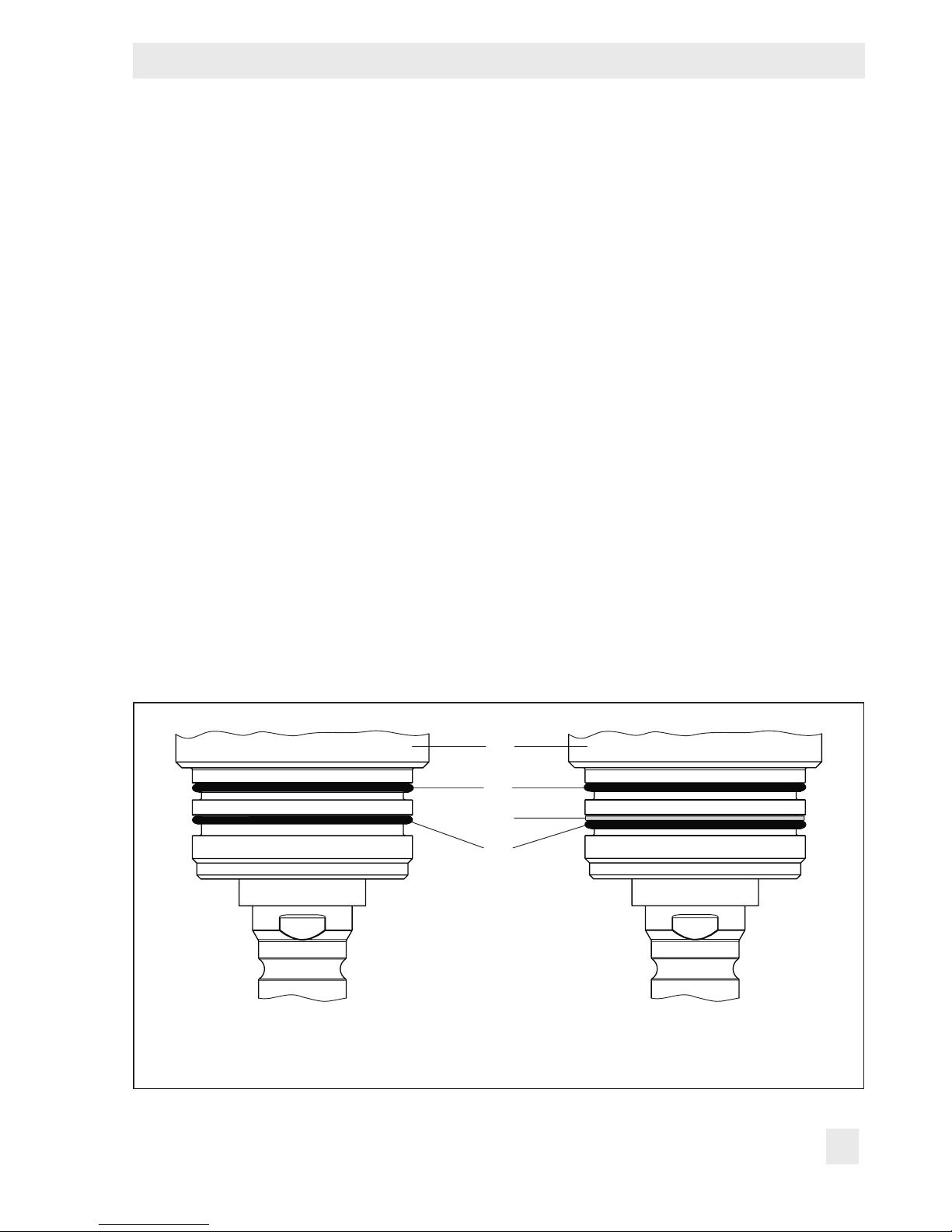
5. Apply a suitable lubricant to the new
O-rings (17). Insert O-rings into the bonnet (2). Make sure that the O-rings rest
on the non-pressurized groove side (see
Fig.8).
>Class900 with FKM O-ring: Place a
new support ring (244) into the groove
above the bottom O-ring (17). Firmly
press the O-ring against the support
ring.
Make sure that the top O-ring rests on
the non-pressurized groove side (see
Fig.8).
6. Apply a suitable lubricant to the bonnet
(2).
7. Place a new tab washer (224) onto the
bonnet (2). Make sure that the ap points
towards the valve front (see Fig.9) and
that the anchorages are inserted in the
corresponding boreholes.
8. Place bonnet (2) with plug and plug stem
(5) onto the body (1). Tighten by hand.
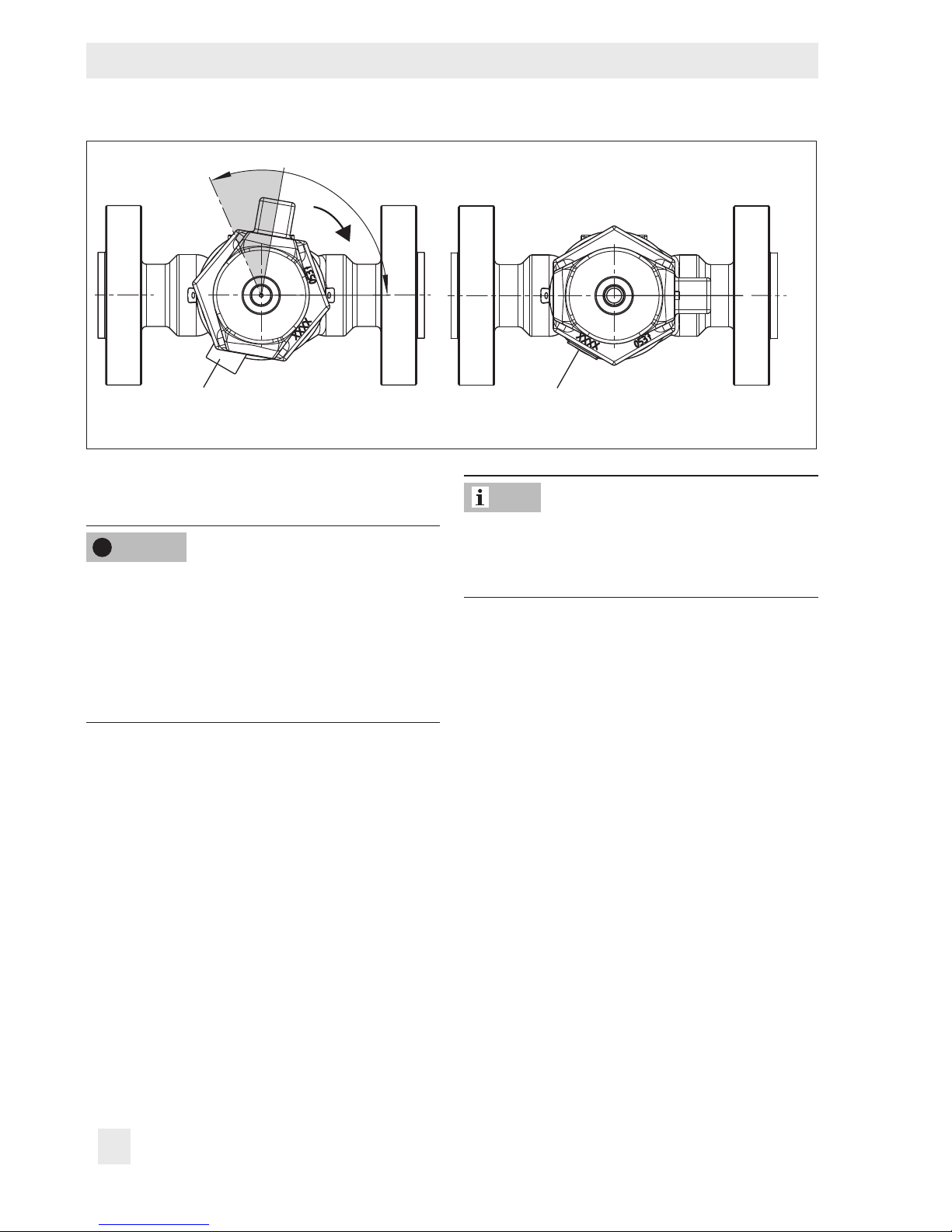
9. When the protruding part of the bonnet
is at an angle of 70 to 100° to its end
position (see Fig.9), screw bonnet (2) into the body (1) observing the tightening
torques.
10. Bend up the ap of the tab washer (224)
so that it rests against the bonnet (see
Fig.9).
2
17
244
17
2 Bonnet
17 O-ring
244 Support ring
Fig.8: O-rings for standard version (left) · O-rings and support ring for standard version >Class900
with FKM O-ring (right)
EB 8823 EN 35
Page 36
Maintenance
70…100°
End position
Flap of tab washer
Fig.9: Mounting the bonnet onto the body
7.1.2 Replacing the packing
!
NOTICE
Risk of valve damage due to abrasion.
The plug and seat facings are very sensitive.
Before unscrewing the bonnet from the body,
apply a signal pressure to the actuator to
slightly lift the plug off the seat. This prevents
the plug and seat from being damaged.
1. Bend down the ap of the tab washer
(224).
2. Apply a signal pressure to the actuator to
slightly lift the plug off the seat. Unscrew
the bonnet (2).
3. Lift bonnet (2) and plug with plug stem
(5) off the body (1). Remove tab washer
(224).
4. Unscrew guide bushing (7) placing a
suitable tool on the ats.
5. Remove stem connector clamp (A28).
See associated actuator documentation.
Bent ap
Note
It is not necessary to completely remove the
actuator from the valve to replace the packing.
6. Pull the plug with plug stem (5) out of the
bonnet (2).
7. Pull all the packing parts out of the pack-
ing chamber using a suitable tool.
8. Replace damaged parts. Clean the pack-
ing chamber thoroughly.
9. Apply a suitable lubricant to the guide
bushing (7), to all the packing parts and
to the plug stem (36).
10. Slide guide bushing (7) and packing
parts over the plug stem. Make sure you
observe the proper order (see Fig.10).
11. Carefully insert plug with plug stem,
packing parts and guide bushing into the
bonnet.
36 EB 8823 EN
Page 37

Maintenance
!
NOTICE
Risk of leakage due to damaged packing
chamber, packing parts and plug stem.
When inserting the assembly into the bonnet
make sure that the packing chamber, packing parts and plug stem do not get damaged. Otherwise leakage may occur.
12. Thread guide bushing (7) into the bonnet
(2) and tighten it placing a suitable tool
on the ats. Observe tightening torques.
13. Check O-rings for damage. Replace
O-rings, if necessary (see section 7.1.1).
14. Apply a suitable lubricant to the bonnet
(2).
15. Place a new tab washer (224) onto the
bonnet (2).
16. Screw bonnet (2) with plug and plug
stem (5) into the body (1). Observe tightening torques.
17. Bend up the ap of the tab washer (224)
so that it rests against the bonnet.
Note
For detailed information on mounting the tab
washer and bonnet see section 7.1.1, steps
7 to 10.
18. Mount stem connector clamp (A28) and
adjust travel. See associated actuator
documentation.
Fig.10: Packing
EB 8823 EN 37
16
12
11
7
15
7 Guide bushing
15 Packing
11 Spring
16 V-ring packing
12 Washer
Page 38

Maintenance
7.1.3 Replacing the seat and
plug
!
NOTICE
Risk of damage to the facing of the seat and
plug due to abrasion and incorrect service
or repair.
The plug and seat facings are very sensitive.
− Before unscrewing the bonnet from the
body, apply a signal pressure to the actuator to slightly lift the plug off the seat. This
prevents the plug and seat from being
damaged.
− Always replace both the seat and plug.
Note
It is not necessary to remove the actuator
from the valve to replace the seat and the
plug.
4. Replace O-rings (17) as described in
section 7.1.1.
5. Unscrew the seat (4) using a suitable
tool.
6. Remove seat ring gasket (127) from the
body (1) and carefully clean the sealing
face. Insert a new seat ring gasket into
the body.
7. Apply a suitable lubricant to the thread
and the sealing cone of the new seat.
8. Screw in the new seat (4) using a suitable tool. Observe tightening torques.
9. Carefully warm up the plug (29) so that
it can be removed from the plug stem
(36) in the next step.
10. Apply a signal pressure to the actuator
so that the ats at the plug stem (36)
emerge from the bonnet. Place wrench
on ats.
11. Place another wrench on the ats of the
plug (29).
Tip
When replacing the seat and plug, we also
recommend replacing the packing. See sec-
tion 7.1.2.
1. Bend down the ap of the tab washer
(224).
2. Apply a signal pressure to the actuator to
slightly lift the plug off the seat. Unscrew
the bonnet (2).
3. Lift bonnet (2) and plug with plug stem
(5) off the body (1). Remove tab washer
(224).
38 EB 8823 EN
12. Loosen plug with wrench while counter-
ing with the top wrench.
13. Apply suitable threadlocker to the thread
of the new plug (29).
14. Screw plug head (29) onto the plug stem
(36) using a suitable tool. Observe tightening torques.
15. Replace packing (15) as described in
section 7.1.2.
16. Apply a suitable lubricant to the bonnet
(2).
17. Place a new tab washer (224) onto the
bonnet (2).
Page 39
18. Screw bonnet (2) with plug and plug
stem (5) into the body (1). Observe tightening torques.
19. Bend up the ap of the tab washer (224)
so that it rests against the bonnet.
Note
For detailed information on mounting the tab
washer and bonnet see section 7.1.1, steps
7 to 10.
7.1.4 Tools and tightening
torques
Maintenance
See Table5.
Table5: Tools and tightening torques for standard version
Standard version
Component Tool
Bonnet (2) –
Guide bushing (7) 1¼” crowfoot wrench 66.38 90
Seat (4)
Socket wrench
7
/
16
NPS1: 1
”
NPS2 to 3: 1
7
/
8
”
NPS1:147.5
NPS2 to 3: 590
Tightening torque
lb-ft Nm
221.27 to
346.65
NPS1: 200
NPS2 to 3: 800
300 to 470
Plug head (29), plug stem (36)
EB 8823 EN 39
Crowfoot wrench
7
/
8
Plug head:
Plug stem:
”
9
/
16
”
14.75 20
Page 40
Maintenance
7.2 Compact version
7.2.1 Replacing the O-rings
!
NOTICE
Risk of valve damage due to abrasion.
The plug and seat facings are very sensitive.
Before unscrewing the bonnet from the body,
apply a signal pressure to the actuator to
slightly lift the plug off the seat. This prevents
the plug and seat from being damaged.
Note
It is not necessary to remove the actuator
from the valve to replace the O-rings.
1. Apply a signal pressure to the actuator to
slightly lift the plug off the seat. Unscrew
the bonnet (2).
7.2.2 Replacing the packing
!
NOTICE
Risk of valve damage due to abrasion.
The plug and seat facings are very sensitive.
Before unscrewing the bonnet from the body,
apply a signal pressure to the actuator to
slightly lift the plug off the seat. This prevents
the plug and seat from being damaged.
1. Apply a signal pressure to the actuator to
slightly lift the plug off the seat. Unscrew
the bonnet (2).
2. Lift bonnet (2), yoke (3) and plug with
plug stem (5) off the body (1).
3. Unscrew guide bushing (7) placing a
suitable tool on the ats.
4. Remove stem connector clamp (A28).
See associated actuator documentation.
2. Lift bonnet (2), yoke (3) and plug with
plug stem (5) off the body (1).
3. Remove O-rings (17) from the bonnet (2)
and carefully clean the grooves.
4. Insert new O-rings (17) into the bonnet
(2).
5. Apply a suitable lubricant to the bonnet
(2).
6. Screw bonnet (2) with yoke (3) and plug
with plug stem (5) into the body (1). Observe tightening torques.
Note
It is not necessary to completely remove the
actuator from the valve to replace the packing.
5. Pull the plug with plug stem (5) out of the
bonnet (2).
6. Pull all the packing parts out of the pack-
ing chamber using a suitable tool.
7. Replace damaged parts. Clean the pack-
ing chamber thoroughly.
8. Apply a suitable lubricant to the guide
bushing (7), to all the packing parts and
to the plug stem (36).
40 EB 8823 EN
Page 41

A16
15
16
12
11
17
Maintenance
Fig.11: Compact version Type3525
T-pattern Valve with Type3571
Pneumatic Actuator
A7
S
A28
92
3
2
7
36
5
29
16
12
11
7
15
127
1 Body
2 Bonnet
3 Yoke
4 Seat
5 Plug (29, 36)
7 Guide bushing
11 Spring
12 Washer
15 Packing (11, 12, 16)
16 V-ring packing
4
1
112
Fig.12: Packing
17 O-ring
29 Plug head
36 Plug stem
92 Lock nut
112 Screw plug
127 Seat ring gasket
A7 Actuator stem
A16 Vent plug
A28 Stem connector clamp
S Signal pressure connection
EB 8823 EN 41
Page 42

Maintenance
9. Slide guide bushing (7) and packing
parts over the plug stem. Make sure you
observe the proper order (see Fig.12).
10. Carefully insert plug with plug stem,
packing parts and guide bushing into the
bonnet.
!
NOTICE
Risk of leakage due to damaged packing
chamber, packing parts and plug stem.
When inserting the assembly into the bonnet
make sure that the packing chamber, packing parts and plug stem do not get damaged. Otherwise leakage may occur.
11. Thread guide bushing (7) into the bonnet
(2) and tighten it placing a suitable tool
on the ats. Observe tightening torques.
12. Check O-rings for damage. Replace
O-rings, if necessary (see section 7.2.1).
13. Apply a suitable lubricant to the bonnet
(2).
14. Screw bonnet (2) with yoke (3) and plug
with plug stem (5) into the body (1). Observe tightening torques.
15. Mount stem connector clamp (A28) and
adjust travel. See associated actuator
documentation.
7.2.3 Replacing the seat and
plug
!
NOTICE
Risk of damage to the facing of the seat and
plug due to abrasion and incorrect service
or repair.
The plug and seat facings are very sensitive.
− Before unscrewing the bonnet from the
body, apply a signal pressure to the actuator to slightly lift the plug off the seat. This
prevents the plug and seat from being
damaged.
− Always replace both the seat and plug.
Tip
When replacing the seat and plug, we also
recommend replacing the packing. See sec-
tion 7.2.2.
Standard plug material (Stellite
Note
It is not necessary to remove the actuator
from the valve to replace the seat and the
plug.
1. Apply a signal pressure to the actuator to
slightly lift the plug off the seat. Unscrew
the bonnet (2).
®
6)
42 EB 8823 EN
2. Lift bonnet (2), yoke (3) and plug with
plug stem (5) off the body (1).
3. Replace O-rings (17) as described in
section 7.2.1.
Page 43

Maintenance
4. Unscrew the seat (4) using a suitable
tool.
5. Remove seat ring gasket (127) from the
body (1) and carefully clean the sealing
face. Insert a new seat ring gasket into
the body.
6. Apply a suitable lubricant to the thread
and the sealing cone of the new seat.
7. Screw in the new seat (4) using a suitable tool. Observe tightening torques.
8. Carefully warm up the plug (29) so that
it can be removed from the plug stem
(36) in the next step.
9. Apply a signal pressure to the actuator
so that the ats at the plug stem (36)
emerge from the bonnet. Place wrench
on ats.
10. Place another wrench on the ats of the
plug (29).
11. Loosen plug with wrench while counter-
ing with the top wrench.
12. Apply suitable threadlocker to the thread
of the new plug (29).
13. Screw plug head (29) onto the plug stem
(36) using a suitable tool. Observe tightening torques.
14. Replace packing (15) as described in
section 7.2.2.
15. Apply a suitable lubricant to the bonnet
(2).
16. Screw bonnet (2) with yoke (3) and plug
with plug stem (5) into the body (1). Observe tightening torques.
Tungsten carbide or ceramic plug
1. Remove stem connector clamp (A28).
See associated actuator documentation.
Note
It is not necessary to completely remove the
actuator from the valve to replace the seat
and plug.
2. Apply a signal pressure to the actuator to
slightly lift the plug off the seat. Unscrew
the bonnet (2).
3. Lift bonnet (2), yoke (3) and plug with
plug stem (5) off the body (1).
4. Replace O-rings (17) as described in
section 7.2.1.
5. Unscrew the seat (4) using a suitable
tool.
6. Remove seat ring gasket (127) from the
body (1) and carefully clean the sealing
face. Insert a new seat ring gasket into
the body.
7. Apply a suitable lubricant to the thread
and the sealing cone of the new seat.
8. Screw in the new seat (4). Observe tightening torques.
9. Replace plug with plug stem (5) and insert it into the bonnet (2).
10. Apply a suitable lubricant to the bonnet
(2).
11. Screw bonnet (2) with yoke (3) and plug
with plug stem (5) into the body (1). Observe tightening torques.
EB 8823 EN 43
Page 44

Maintenance
12. Mount stem connector clamp (A28) and
adjust travel. See associated actuator
documentation.
7.2.4 Tools and tightening
torques
See Table6.
7.3 Preparation for return
shipment
Defective valves can be returned to
SAMSON for repair.
Proceed as follows to return valves to
SAMSON:
1. Put the control valve out of operation (see
section9).
2. Decontaminate the valve. Remove any
residual process medium.
3. Fill in the Declaration on Contamination,
which can be downloaded from the
SAMSONAG website at
uwww.samson.de > Services > Check-
lists for after-sales service > Declaration
on Contamination.
4. Send the valve together with the lled-in
form to your nearest SAMSON subsidiary. SAMSON subsidiaries are listed on
our website at
uwww.samsoncontrols.com > Contact.
Table6: Tools and tightening torques for compact version
Compact version
Component Tool
1
/
16
Bonnet (2) 2
Yoke (3) – 110.63 150
Guide bushing (7)
Seat (4)
Plug head (29), plug stem (36)
” socket wrench 368.78 500
11
/
16
” crowfoot wrench 44.25 60
¾” socket wrench with
hexagon bit socket
Crowfoot wrench
9
/
16
Plug head:
Plug stem:
”
3
/
8
”
Tightening torque
lb-ft Nm
59 80
5.9 8
44 EB 8823 EN
Page 45

7.4 Ordering spare parts and
operating supplies
Spare Parts
See section10.3 for details on spare parts.
Lubricants
Details on suitable lubricants can be found in
the parts list.
Note
For further information contact your nearest
SAMSON subsidiary or the SAMSON Aftersales Service department.
Maintenance
EB 8823 EN 45
Page 46

Malfunctions
8 Malfunctions
Depending on the operating conditions, check the valve at certain intervals to prevent possi-
ble failure before it can occur. Operators are responsible for drawing up a test plan.
Tip
SAMSON’s After-sales Service department can support you to draw up an inspection plan
for your plant.
8.1 Troubleshooting
Malfunction Possible reasons Recommended action
Actuator or plug stem does not
move on demand.
Actuator or plug stem does not
move through the whole range.
The valve leaks to the
atmosphere (fugitive emissions).
Actuator is blocked. Check attachment.
Unblock the actuator.
Signal pressure too low. Check the signal pressure.
Check the signal pressure line
for leakage.
Signal pressure too low. Check the signal pressure.
Check the signal pressure line
for leakage.
The packing is defective. Replace packing (see sec-
tion7.1.2 or 7.2.2) or contact
SAMSON's After-sales Service
department.
Flange joint loose. Check the ange joint. Re-tight-
en, if necessary.
Thread joint loose or seal worn. Check the threaded joint.
Re-tighten, if necessary.
Check the seal at the threaded
joint. Exchange, if necessary.
O-rings worn out. Replace O-rings at the bonnet
(see section7.1.1 or 7.2.1) or
contact SAMSON’s After-sales
Service department.
46 EB 8823 EN
Page 47

Malfunctions
Malfunction Possible reasons Recommended action
Increased ow through closed
valve (seat leakage)
Dirt or other foreign particles
deposited between the seat and
plug.
Valve trim is worn out. Replace seat and plug (see sec-
Shut off the section of the pipeline and ush the valve.
tion7.1.3 or 7.2.3) or contact
SAMSON's After-sales Service
department.
Note
Contact SAMSON’s After-sales Service department for malfunctions not listed in the table.
8.2 Emergency action
Upon supply air or control signal failure, the
valve moves to its fail-safe position (see section3.1).
Operators are responsible for emergency action to be taken in the plant.
In the event of a valve malfunction:
1. Depressurize the plant and interrupt the
medium ow.
2. Check the valve for damage. If neces-
sary, contact SAMSON’s After-sales Ser-
vice department.
Putting the valve back into operation after
a malfunction
Î Slowly resume medium ow in the pipe-
line.
EB 8823 EN 47
Page 48

Decommissioning and disassembly
9 Decommissioning and
disassembly
!
DANGER
Risk of bursting in pressure equipment.
Control valves and pipelines are pressure
equipment. Improper opening can lead to
valve components bursting.
− Before starting any work on the control
valve, depressurize all plant sections concerned and the valve.
− Drain the process medium from all the
plant sections concerned as well as the
valve.
− Wear personal protective equipment.
!
WARNING
Risk of personal injury due to sudden escape
of process medium.
The valve has a safety bleed to detect damaged or worn O-rings. The process medium
may escape suddenly and at high pressure.
− Wear protective clothing, gloves and eye-
wear when working near or on the valve.
− Do not stay in the range of the safety bleed
longer than necessary.
Wear protective clothing, gloves and eyewear.
!
WARNING
Risk of burn injuries due to hot or cold components and pipeline.
Valve components and the pipeline may become very hot or cold. Risk of burn injuries.
− Allow components and pipelines to cool
down or heat up.
− Wear protective clothing and gloves.
9.1 Decommissioning
To decommission the control valve for service
and repair work or disassembly, proceed as
follows:
1. Interrupt the medium ow.
2. Completely drain the pipelines and
valve.
3. Disconnect and lock the pneumatic air
supply to depressurize the actuator.
4. If necessary, allow the pipeline and valve
components to cool down or heat up.
9.2 Removing the valve from
!
WARNING
Risk of personal injury due to residual process medium in the valve.
While working on the valve, residual process
medium can escape and, depending on its
properties, may lead to personal injury, e.g.
(chemical) burns.
48 EB 8823 EN
the pipeline
Version with anges
1. Put the control valve out of operation (see
section9.1).
2. Unbolt the ange joint.
3. Remove the valve from the pipeline (see
section4.2).
Page 49

Version with threaded ends
1. Put the control valve out of operation (see
section9.1).
2. Unscrew the valve from the pipeline.
3. Remove the valve from the pipeline (see
section4.2).
9.3 Removing the actuator
from the valve
See associated actuator documentation.
9.4 Disposal
Decommissioning and disassembly
Î Observe local, national and internation-
al refuse regulations.
Î Do not dispose of components, lubricants
and hazard substances together with
your other household waste.
EB 8823 EN 49
Page 50

Appendix
10 Appendix
10.1 Customer inquiries
Contact SAMSON’s After-sales Service department for support concerning maintenance or repair work or when malfunctions
or defects arise.
E-mail
You can reach the After-sales Service depart-
ment at samson@samsongroupna.com.
Addresses of SAMSONAG and its subsidiaries
The addresses of SAMSON AG, its subsidiaries, representatives and service facilities
worldwide can be found on the SAMSON
website, in all SAMSON product catalogs or
on the back of these Mounting and Operat-
ing Instructions.
10.2 Certicates
Certicates are available on request. Please
contact After-sales Service department at
samson@samsongroupna.com.
Required specications
Please submit the following details:
− Order number and position number in
the order
− Type, model number, nominal size and
valve version
− Pressure and temperature of the process
medium
− Flow rate
− Bench range of the actuator (e.g. 9 to
35psi)
− Is a strainer installed?
− Installation drawing
50 EB 8823 EN
Page 51

EB 8823 EN 51
Page 52

Appendix
10.3 Spare parts
Standard version Type3525 Globe Valve
1 Body
2 Bonnet
4 Seat
5 Plug (29, 36)
7 Guide bushing
11 Spring
12 Washer
15 Packing (11, 12, 16)
16 V-ring packing
17 O-ring
29 Plug head
36 Plug stem
60 Yoke assembly with travel indicator
(82, 83, 84)
82 Screw
83 Hanger
84 Travel indicator scale
91 Protective cap
127 Seat ring gasket
224 Tab washer
244 PTFE support ring
1)
only for versions >Class900 with FKM O-ring
1)
52 EB 8823 EN
Page 53

Standard version Type3525 Globe Valve
Appendix
15
2
17
244
224
16
12
11
7
84
83
82
36
29
60
5
4
127
1
91
1
91
EB 8823 EN 53
Page 54

Appendix
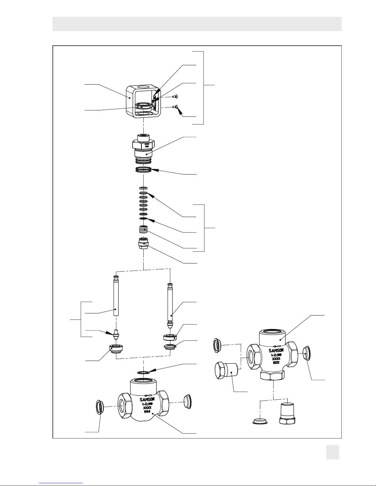
Compact version Type3525 Globe Valve
and T-pattern Valve
1 Body
2 Bonnet
3 Yoke
4 Seat
5 Plug (29, 36)
7 Guide bushing
11 Spring
12 Washer
15 Packing (11, 12, 16)
16 V-ring packing
17 O-ring
29 Plug head
36 Plug stem
60 Yoke assembly with travel indicator
(82, 83, 84)
82 Screw
83 Hanger
84 Travel indicator scale
91 Protective cap
92 Lock nut
112 Screw plug
127 Seat ring gasket
221 Seat ring
54 EB 8823 EN
Page 55
Appendix
3
92
83
84
82
2
17
16
12
Compact version Type3525
Globe Valve and T-pattern Valve
60
15
11
7
5
36
5
29
4
221
4
127
112
1
91
91
EB 8823 EN 55
1
Page 56

SAMSON CONTROLS INC.
4111 Cedar Boulevard · Baytown, Texas 77523-8588
Phone: +1 281 383-3677 · Fax: +1 281 383-3690
samson@samsongroupna.com · www.samsoncontrols.com
EB 8823 EN
2017-03-15 · English
 Loading...