

Page 1
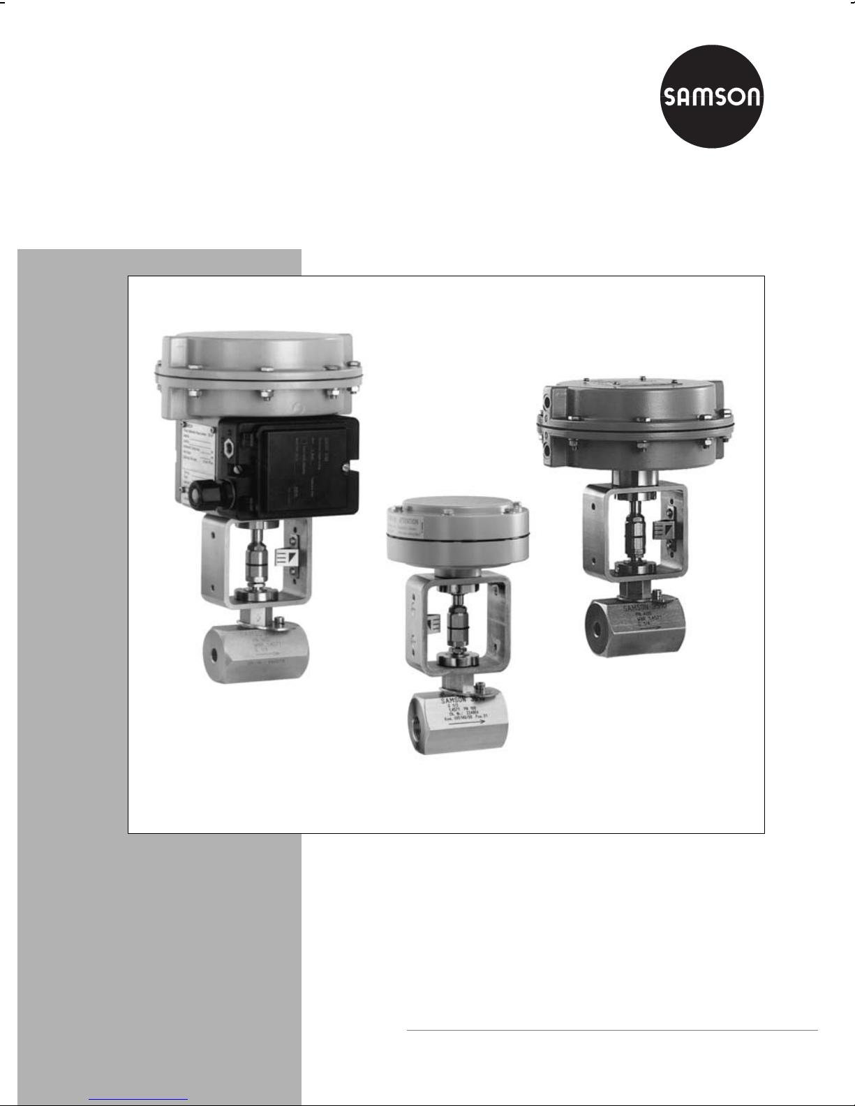
Pneumatic Control Valve
Type 3510-1 and Type 3510-7
Type 3510-7 with 120 cm2 actuator
and integrated positioner
Fig. 1 ⋅ Pneumatic control valves
Type 3510-1 with 60 cm
Mounting and
Operating Instructions
EB 8091 EN
Edition July 2002
2
actuator
Type 3510-1 with 120 cm
2
actuator
Page 2

Contents
Contents Page
1 Design and principle of operation . . . . . . . . . . . . . . . . . . . . . . 4
2 Assembling and adjusting valve and actuator . . . . . . . . . . . . . . . . 6
2.1 Signal pressure connection . . . . . . . . . . . . . . . . . . . . . . . . . . 6
2.2 Assembly and adjustment . . . . . . . . . . . . . . . . . . . . . . . . . . 7
3 Installation . . . . . . . . . . . . . . . . . . . . . . . . . . . . . . . . . 8
3.1 Mounting position . . . . . . . . . . . . . . . . . . . . . . . . . . . . . . 8
4 Operation – Reversing the operating direction . . . . . . . . . . . . . . . . 8
5 Troubleshooting . . . . . . . . . . . . . . . . . . . . . . . . . . . . . . . 9
5.1 Replacing the stuffing box packing . . . . . . . . . . . . . . . . . . . . . . 10
5.2 Replacing seat and plug . . . . . . . . . . . . . . . . . . . . . . . . . . . 12
6 Customer inquiries . . . . . . . . . . . . . . . . . . . . . . . . . . . . . . 14
Note!
Non-electrical control valves which do not have a valve body lined with an insulating
material coating do not have their own potential ignition source according to the risk assess-
ment in the rare incident of an operating fault, corresponding to EN 13463-1: 2001 paragraph 5.2, and therefore do not fall within the scope of the European Directive 94/9/EC.
2
EB 8091 EN
Page 3
Safety instructions
The device may only be assembled, started up or operated by trained and ex-
perienced personnel familiar with the product.
According to these mounting and operating instructions, trained personnel is
referred to as individuals who are able to judge the work they are assigned to
and recognize possible dangers due to their specialized training, their knowledge and experience, as well as their knowledge of the applicable standards.
Any hazards which could be caused in the control valve by the process me-
dium, the operating pressure, the signal pressure or the moving parts are to
be prevented by means of the appropriate measures.
In addition, it is necessary to make sure that the control valve is only used in
areas where the operating pressure and temperatures do not exceed the operating values which are based on the valve sizing data submitted in the order.
Proper shipping and appropriate storage are assumed.
EB 8091 EN
3
Page 4
Design and principle of operation
1 Design and principle of operation
The pneumatic control valve consists of a
Type 3510 Micro-flow Valve (globe or
angle body style) and either a Type 3271-5
Pneumatic Actuator (Type 3510-1 Control
Valve) or a Type 3277-5 Pneumatic Actuator (Type 3510-7 Control Valve).
The modular design enables the actuators to
be exchanged, and the standard valve version to be enhanced to a version incorporating either a bellows seal or an insulating
section.
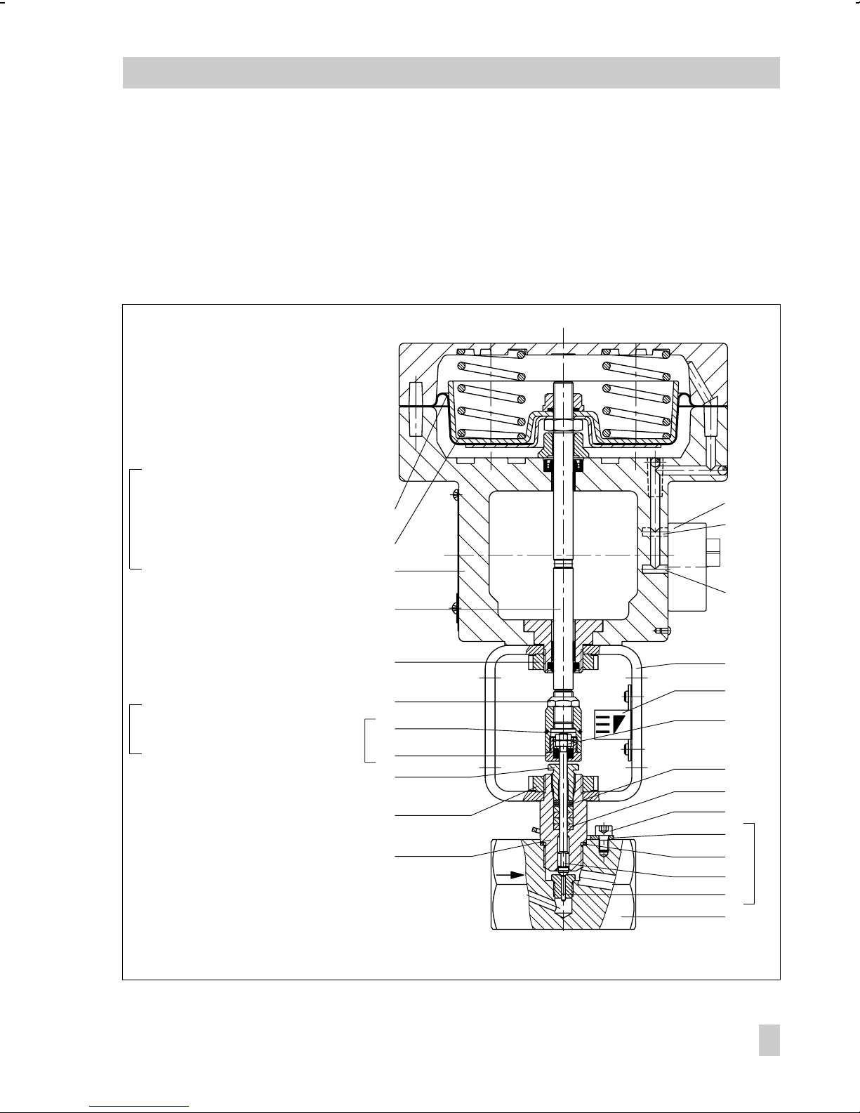
The process medium flows through the valve
in the direction indicated by the arrow. The
position of the valve plug (3) determines the
cross-sectional area of flow between the
valve seat (2) and the plug.
A change in the signal pressure acting on
the diaphragm of the actuator causes the
valve plug to move correspondingly. The
plug stem (6) is connected to the actuator
stem (8.1) via the stem connector (7) and
sealed with an adjustable stuffing box with
packing that contains PTFE sealing rings.
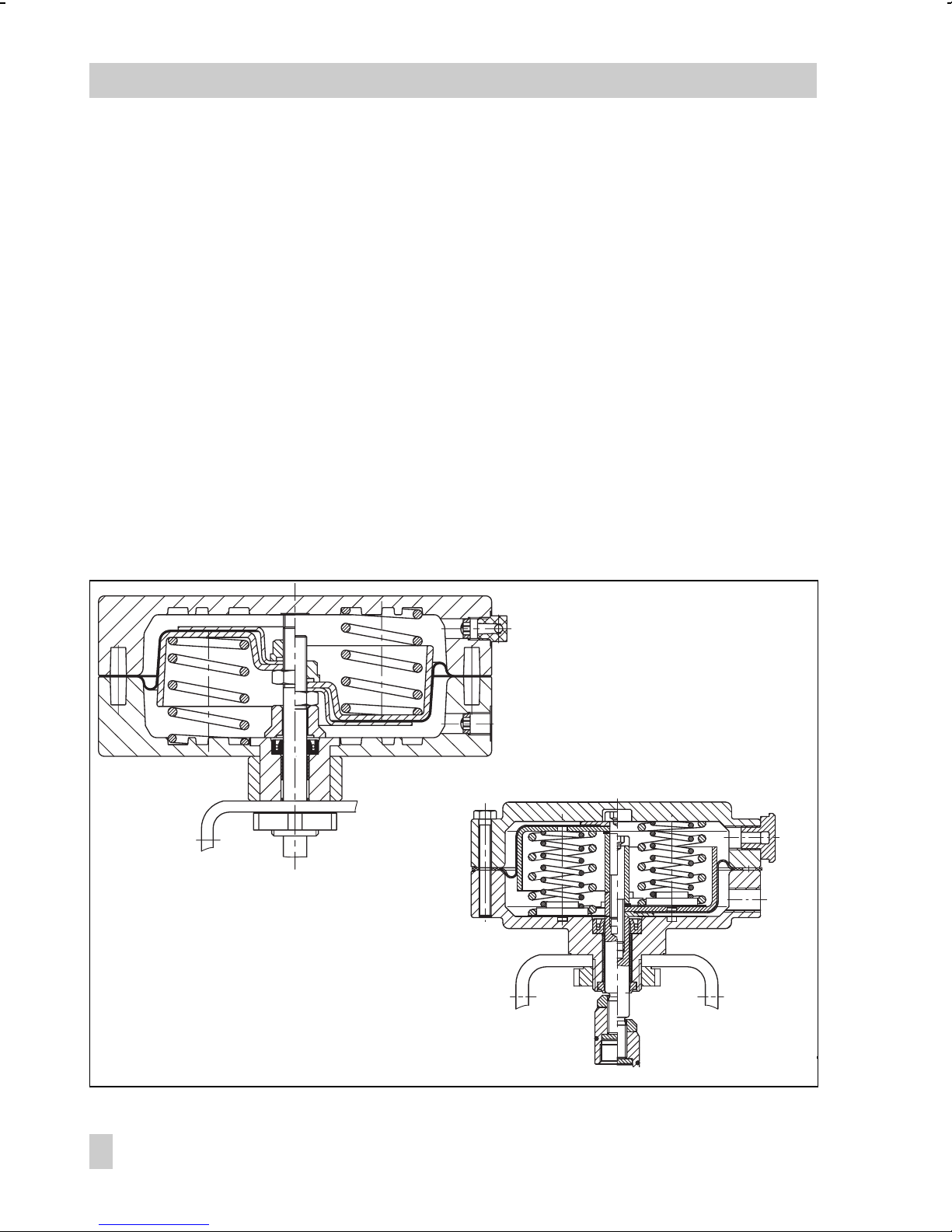
Fail-safe action:
Depending on the arrangement of the
springs (8.3) in the actuator, the control
valve has two different fail-safe actions:
Actuator stem
retracts
Type 3271-5 Actuator with 120 cm
Fig. 2 ⋅ Type 3271-5 Actuators
4
EB 8091 EN
2
Actuator stem
extends
Type 3271-55 with 60 cm
Actuator stem
retracts
2
Actuator stem
extends
Page 5
Design and principle of operation
Actuator stem extends:
When the signal pressure is reduced or in
case of a supply air failure, the springs
move the actuator stem downwards and
close the valve. The valve is opened against
the spring force, when the signal pressure
increases.
1Body
1.1 Screw
2Seat trim
2.1 Seat
2.2 Plug
2.3 Sealing ring
2.4 Anti-rotation device with
trim identification number
3Nuts
4Packing rings
4.1 Packing washer
5 Valve bonnet
5.1 Threaded bushing
5.2 Slotted round nut
6Yoke
6.1 Travel indicator scale
7 Stem connector
7.1 Stem connector nut
7.2 Stem connector sleeve
7.3 Lock nut
8Actuator
8.1 Actuator stem
8.2 Slotted round nut
8.3 Spring
8.4 Diaphragm
14 Connecting or switchover plate
14.1 Signal pressure route
"Actuator stem extends"
14.2 Signal pressure route
"Actuator stem retracts"
8.4
8.3
8
8.1
8.2
7.3
7.1
7
7.2
5.1
5.2
5
Actuator stem retracts:
When the signal pressure is reduced or in
case of a supply air failure, the springs
move the actuator stem upwards and open
the valve. The valve is closed against the
spring force, when the signal pressure increases.
14
14.1
14.2
6
6.1
3
4.1
4
1.1
2.4
2.3
2.2
2.1
1
2
Fig. 3 ⋅ Sectional drawing of micro-flow control valve with Type 3277-7 Actuator
EB 8091 EN
5
Page 6

Assembling and adjusting valve and actuator
2 Assembling and adjusting valve
and actuator
If control valve and actuator have not been
pre-assembled by the manufacturer, observe the different signal pressure connections of the actuators on assembly.
2.1 Signal pressure connection
Type 3510-1 Control Valve
with Type 3271-5 Actuator
The signal pressure connection for fail-
safe action "Actuator stem extends" is located at the bottom of the diaphragm
case. For "Actuator stem retracts", the
connection is to be found at the top of
the diaphragm case.
Type 3510-7 Control Valve
with Type 3277-5 Actuator
Actuator with positioner:
The signal pressure is transferred to the diaphragm case via bores at the left and right
side of the yoke and via a switchover plate
(accessories). The fail-safe action "Actuator
stem extends" or "Actuator stem retracts"
determines how the switchover plate needs
to be aligned to the mark.
Turn the switchover plate, so that the ap-
propriate symbol for the fail-safe action
is aligned to the mark.
Whether the actuator is attached to the
left or right depends on the operating direction (>>) or (<>) of the positioner.
Actuator without positioner:
Instead of a switchover plate, a connecting
plate (accessories) is required if the actua-
tor is used without positioner
Here, the signal pressure is transferred to
the diaphragm case directly via the signal
pressure connection of the connecting plate.
Turn the connecting plate, so that the ap-
propriate symbol for the fail-safe action
"Actuator stem extends" or "Actuator
stem retracts" is aligned to the mark.
Make absolutely sure that the gasket of
the connecting plate is inserted correctly.
The connecting plate provides bores for
NPT and G threads. Seal the unused connection with a rubber gasket and a
square plug.
Accessories:
Switchover plate and connecting plate need
to be ordered as accessories.
Note that actuators with device modification
index 01, e.g. 3277-531xxx20.01 (old =
.00) must be equipped with new plates.
Old and new plates are not interchangeable.
Switchover plate new Order no. 1400-6822
old Order no. 1400-6819
Connecting platenew Order no. 1400-6823
old G thread Order no. 1400-6820
old NPT thread Order no. 1400-6821
6
EB 8091 EN
Page 7

Assembling and adjusting valve and actuator
Note!
When used in connection with the microflow valve, the pneumatic actuators with failsafe action "Actuator stem retracts" are
limited to the max. permissible supply pressures [bar] listed in the table.
For actuators with fail-safe action "Actuator
stem extends", the max. supply pressure is
limited to 4 bar.
Valves with positioners are to be adjusted
to these max. perm. supply pressures.
Signal pressure
range
0.2 to 1 0.4 to 0.8 2.5
0.4 to 2.0 0.8 to 1.6 3.3
1.4 to 2.3 1.7 to 2.1 3.8
2.1 to 3.3 2.4 to 3.0 4.7
Adjusted to Max. perm.
pressure
2.2 Assembly and adjustment
For actuators with a switchover plate for attachment of a positioner, a suitable adapter
needs to be connected to the bores at the
side. Alternatively, the connecting plate
(Fig. 4, right) can be used.
1. On the actuator stem, loosely screw
both stem connector nut (7.1) and lock
nut (7.3) all the way up (Fig. 3).
2. Slide slotted round nut (8.2 ) over both
coupling nut and lock nut.
3. Place the actuator on the yoke (7) and
fasten with slotted round nut (8.2). For
fail-safe action "Actuator stem extends", apply approx. 50 % of the signal pressure range (see nameplate) to
the signal pressure connection of the actuator using a pressure regulator, caus-
Switchover plate
Signal
pressure
Actuator stem extends
Left Attachment Right
Fig. 4 ⋅ Signal pressure connections
Signal pressure
Signal
pressure
Symbol
Mark
Actuator stem retracts
Left Attachment Right
Connecting plate
Actuator stem
extends retracts
EB 8091 EN
7
Page 8

Installation
ing the actuator stem to retract far
enough to screw together stem connector nut (7.1) and stem connector sleeve
(7.2).
4. Screw together stem connector sleeve
(7.2) and stem connector nut (7.1) as
tightly as possible.
5. Apply lower range value of the signal
pressure range to the signal pressure
connection.
For a signal pressure range (bench
range) of, for example, 0.4 to 0.8 bar
and an actuator with fail-safe action
"Actuator stem extends", the lower signal pressure range value is 0.4 bar; for
"Actuator stem retracts" it is 0.8 bar.
6. Rotate stem connector (7) on actuator
stem until plug stem moves from the
closed position at the corresponding initial value. To do so, change signal
pressure each time using the pressure
regulator, and return to the initial lower
range value.
7. Fasten lock nut (7.3) to secure the stem
connector.
3Installation
3.1 Mounting position
Any desired mounting position is possible.
Note! Make sure the valve is installed free
of stress. If necessary, support the pipes
near the connections.
Flush pipes thoroughly before installing the
valve.
For valve versions with bellows seal or insulating section, which are installed in pipes
to be insulated, do not insulate the bellows
intermediate piece or insulating section (9).
Test connection
The version with metal bellows seal can be
equipped with a test connection (16) with
G 1/8 thread at the bellows seal. This connection is used to check the tightness of the
bellows.
It is recommended to install a suitable leakage indicator, in particular when explosive
and hazardous media are used.
8. Align travel indicator scale (6.1) to the
black ring on the stem connector.
8
EB 8091 EN
4 Operation - Reversing the operating direction
If it becomes necessary to reverse the failsafe action of the actuator from "Actuator
stem extends" to "Actuator stem retracts" or
vice versa, refer to the mounting and operating instructions of the actuator for details.
EB 8310 EN for Type 3271-5,
EB 8311 EN for Type 3277-5.
Page 9

5 Troubleshooting
If the valve leaks, the packing may be defective or, in the bellows version, the metal bellows may be defective.
Tight shut-off of the valve can also be impaired by impurities or other foreign particles between seat and plug, or by damaged seat joints.
Remove the affected components, clean
them thoroughly and, if necessary, replace
them.
Troubleshooting
Caution!
Make sure to relieve the pressure
from the pressurized part of the
plant and, depending on the medium, drain it completely before performing maintenance. For high temperatures, allow the plant to cool
down to ambient temperature.
Disconnect and lshut off the supply
air as well as the control signals to
prevent against danger posed by
moving parts at the valve.
As valves are not free of dead cavities, remember that there might still
be residual media in the valve. This
particularly applies for valve version
with bellows seal or insulating section.
Note!
The seat and special tools required for installation as well as the appropriate tightening torques are to be found in the SAM-
SON Special tools brochure WA 029.
A complete tool kit for the Type 3510
Micro-flow Valve can be ordered separately
(order no. 1280-3050).
It is recommended to remove the
valve from the pipeline for maintenance.
EB 8091 EN
9
Page 10

Troubleshooting
5.1 Replacing the stuffing box
packing
If leakage occurs at the stuffing box, the
stuffing box packing must be replaced as
described below.
1. For actuators with "Actuator stem extends", apply approx. 50 % of the signal pressure range (see nameplate) to
the actuator, causing the actuator stem
to retract.
Place socket wrench (width across flats
(SW) 17) on stem connector nut (7.1)
and unscrew stem connector sleeve
(7.2) with a second SW 17 wrench.
2. Unscrew the bottom slotted round nut
(5.2). Remove actuator (8) including
yoke (6) from the valve, turning the
slotted round nut (5.2), so that a groove
points towards the travel indicator scale
(6.1).
3. Take out the nuts (3). Remove stem connector sleeve (7.2) from the plug stem.
4. Remove the screw (1.1) and the anti-rotation device (2.4). Unscrew the valve
bonnet (5) from the valve body.
5. Unscrew threaded bushing (5.1). Pull
the plug stem, together with the plug
(2.2), out of the valve bonnet (5).
For versions with bellows intermediate
piece or insulating section, separate
valve bonnet and bellows intermediate
piece/insulating section (9). The plug
stem extension (10.1, Fig. 6) remains
fixed in the extension bonnet.
6. Remove packing washers (4.1) and
packing rings (4) from the packing
chamber using a suitable tool. Make
sure not to damage the sealing edges.
Clean packing chamber thoroughly.
Assembly:
7. Insert new sealing rings. Start with a
white ring, followed by two black rings
and another white one. Make sure that
the butt joints of successive rings are
not positioned on top of each other.
8. Insert packing washer(s) (4.1). Tighten
threaded bushing (5.1) manually.
9. Slide plug stem with plug (2.2) into the
valve bonnet as far as it will go. Tighten
threaded bushing (5.1), observing a
minimum gap of 1.3 mm between valve
bonnet and threaded bushing. If this is
not the case, add required number of
packing washers (4.1) (min. 1, max. 3
washers).
10. Insert new sealing ring (2.3) into the
body. Screw together valve bonnet and
body.
11. Place anti-rotation device (2.4) on the
valve bonnet and tighten it, so that the
fastening screw (1.1) is seated in the oblong hole.
12. Push stem connector sleeve (7.2) onto
the plug stem with the thread facing upwards. Screw on nuts (3).
Lock nuts against each other, so that approx. 1 mm of the thread is still visible.
13. Place actuator including yoke onto
valve bonnet. Tighten with slotted round
nut (5.2).
For actuators with "Actuator stem extends", apply approx. 50 % of the signal pressure range (see nameplate) to
the actuator using a pressure regulator,
causing the actuator stem to retract far
10
EB 8091 EN
Page 11

Troubleshooting
enough to screw together stem connector nut (7.1) and stem connector sleeve
(7.2).
14. Screw together stem connector sleeve
(7.2) and stem connector nut (7.1) as
tightly as possible. Tighten lock nut
(7.3).
8.1
7.3
7.1
7
7.2
15. Check adjustment according to instructions given in section 2.2, items 5 to 8.
6
6.1
3
5.1
1Body
1.1 Screw
2Seat trim
2.1 Seat
2.2 Plug
2.3 Sealing ring
2.4 Anti-rotation device
3Nuts
4Packing rings
4.1 Packing washer
5 Valve bonnet
5.1 Threaded bushing
5.2 Slotted round nut
6Yoke
6.1 Travel indicator scale
7 Stem connector
7.1 Stem connector nut
7.2 Stem connector sleeve
7.3 Lock nut
8.1 Actuator stem
Fig. 5 ⋅ Replacing the stuffing box packing
5.2
5
4.1
4
1.1
2.4
2.3
2
2.2
2.1
1
EB 8091 EN
11
Page 12

Troubleshooting
5.2 Replacing seat and plug
Standard version:
For assembly/disassembly, proceed as
described in section 5.1. Additionally,
unscrew the seat (2.1) using a socket
wrench.
Important!
If, on replacing the seat trim (parts 2.1 to
2.4), you wish to install a trim with a different K
must also be replaced with the one included
in the new trim. On the anti-rotation device
as well as on the seat and plug themselves,
there is an identification number indicating
which trim parts belong together as well as
the material, K
Never combine seats and plugs belonging
to different trims!
The seat thread imposes restrictions on replacing trims. Only the K
ated seat threads can be exchanged (see
table below).
value, the old anti-rotation device
V
value and characteristic.
VS
values of associ-
V
Versions with bellows seal or insulating
section:
Unscrew valve bonnet (5).
In the insulating section version, remove
insulating section (9) from the valve
body, so that the plug stem including
plug (2.2) can be unscrewed from the
plug stem extension (10.1).
In the metal bellows version, unscrew bel-
lows seal (10) together with plug stem extension (10.1) and plug (2.2) from the
bellows intermediate piece (9) using a
bellows nut wrench.
Unscrew plug stem including plug from
the plug stem extension and remove bellows intermediate piece from valve body.
Before reassembling, replace sealing rings
(9.1 and 9.2). In addition, secure bellows intermediate piece (9) or insulating section (9)
as well as the valve bonnet using additional
anti-rotation devices (11 and 12).
The upper anti-rotation devices (2.4 and
12) are secured by the disk (15).
Table seat thread
Seat thread M10 x 1 M16 x 1
value 0.0001 to 0.4 0.63 to 1.6
K
VS
PN max. 400 100
12
EB 8091 EN
Page 13

2.4
15
12
9.1
13
1.1 Screw
2.2 Plug
2.4 Anti-rotation device with
trim identification number
5 Valve bonnet
9 Bellows intermediate piece/insulating section
9.1 Sealing ring
9.2 Sealing ring
10 Bellows seal
10.1 Plug stem extension
(in version with insulating section without
metal bellows)
11 Anti-rotation device
12 Anti-rotation device
13 Screw
15 Disk
16 Test connection (optional)
16
9.2
10
10.1
9
1.1
11
2.2
Fig. 6 ⋅ Metal bellows version
EB 8091 EN
13
Page 14

Customer inquiries
6 Customer inquiries
Please include the following details in your
inquiry:
Order number
Type, product and identification number
Valve style: globe or angle valve
Nominal size and pressure of the valve,
additionally K
tion number of the attached trim
Pressure, density, viscosity and tempera-
ture of the flow medium
Flow rate in m3/h
Direction of flow through the valve
Bench range (signal pressure range, e.g.
0.2 to 1 bar) of the attached actuator
Has a strainer been installed?
Installation drawing
value and the identifica-
VS
For dimensions and weights of the valve
versions, refer to Data Sheet T 8091 EN.
14
EB 8091 EN
Page 15

EB 8091 EN
15
Page 16

SAMSON AG ⋅ MESS- UND REGELTECHNIK
Weismüllerstraße 3 ⋅ 60314 Frankfurt am Main ⋅ Germany
Phone: +49 69 4009-0 ⋅ Fax: +49 69 4009-1507
Internet: http://www.samson.de
EB 8091 EN
S/Z 2002-07
 Loading...