

Page 1
Mounting and
Operating Instructions
EB 8091-1 EN
Translation of original instructions
Edition September 2016
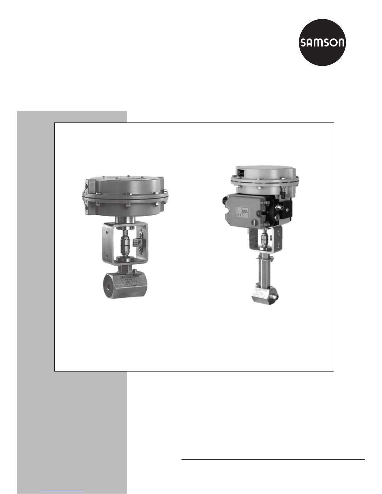
Type3510-1 (left) and Type3510-7 (right) Pneumatic Control Valves
Type3510 Micro-ow Valve
In combination with an actuator,
e.g. a SAMSON Type3271 or Type3277 Pneumatic Actuator
ANSI version
Page 2
2 EB 8091-1 EN
Note on these mounting and operating instructions
These mounting and operating instructions assist you in mounting and operating the device
safely. The instructions are binding for handling SAMSON devices.
Î For the safe and proper use of these instructions, read them carefully and keep them for
later reference.
Î If you have any questions about these instructions, contact SAMSON‘s After-sales Service
Department (aftersalesservice@samson.de).
The mounting and operating instructions for the devices are included in
the scope of delivery. The latest documentation is available on our website
(www.samson.de) > Product documentation. You can enter the document
number or type number in the [Find:] eld to look for a document.
Denition of signal words
Hazardous situations which, if not avoided,
will result in death or serious injury
Hazardous situations which, if not avoided,
could result in death or serious injury
Property damage message or malfunction
Additional information
Recommended action
DANGER
!
WARNING
!
NOTICE
!
Note
Tip
Page 3

Contents
EB 8091-1 EN 3
1 Safety instructions and measures ...................................................................5
1.1 Notes on possible severe personal injury .........................................................7
1.2 Notes on possible personal injury ...................................................................8
1.3 Notes on possible property damage ................................................................9
2 Markings on the control valve ......................................................................10
2.1 Body inscription ...........................................................................................10
2.2 Actuator nameplate ......................................................................................11
2.3 Material number ..........................................................................................11
3 Design and principle of operation ................................................................12
3.1 Fail-safe positions ........................................................................................12
3.2 Versions ......................................................................................................14
3.3 Technical data .............................................................................................14
4 Measures for preparation ............................................................................20
4.1 Unpacking ..................................................................................................20
4.2 Transporting and lifting ................................................................................20
4.2.1 Transporting ................................................................................................20
4.2.2 Lifting ..........................................................................................................20
4.3 Storage .......................................................................................................21
4.4 Preparation for installation ............................................................................21
5 Mounting and start-up ................................................................................. 23
5.1 Mounting the actuator onto the valve .............................................................23
5.2 Installing the valve into the pipeline ...............................................................23
5.2.1 Checking the installation conditions ...............................................................23
5.2.2 Additional ttings .........................................................................................25
5.2.3 Installing the control valve .............................................................................25
5.3 Quick check ................................................................................................26
6 Operation ...................................................................................................28
6.1 Working in manual mode ............................................................................. 28
7 Servicing.....................................................................................................30
7.1 Replacing the gasket ....................................................................................31
7.1.1 Standard version..........................................................................................31
7.1.2 Version with insulating section .......................................................................31
Page 4

4 EB 8091-1 EN
Contents
7.1.3 Version with bellows seal ..............................................................................34
7.2 Replacing the packing ..................................................................................36
7.3 Replacing the seat and plug ..........................................................................38
7.3.1 Standard version..........................................................................................38
7.3.2 Version with insulating section .......................................................................39
7.4 Preparation for return shipment ..................................................................... 40
7.5 Ordering spare parts and operating supplies .................................................41
8 Malfunctions ...............................................................................................42
8.1 Troubleshooting ...........................................................................................42
8.2 Emergency action ........................................................................................43
9 Decommissioning and disassembly ..............................................................44
9.1 Decommissioning .........................................................................................44
9.2 Removing the valve from the pipeline .............................................................44
9.3 Removing the actuator from the valve ............................................................45
9.4 Disposal ......................................................................................................45
10 Appendix ....................................................................................................45
10.1 After-sales service ........................................................................................45
10.2 Spare parts .................................................................................................46
Page 5

EB 8091-1 EN 5
Safety instructions and measures
1 Safety instructions and measures
Intended use
The SAMSON Type3510 Micro-ow Valve in combination with an actuator (e.g. Type3271
or Type3277 Pneumatic Actuator) is designed to regulate the ow rate, pressure or temperature of liquids, gases or vapors. The micro-ow valve is suitable for controlling low ow
rates, e.g. in pilot plants and technical research facilities. The valve with its actuator is designed to operate under exactly dened conditions (e.g. operating pressure, process medium, temperature). Therefore, operators must ensure that the control valve is only used in applications that meet the specications used for sizing the valve at the ordering stage. In case
operators intend to use the control valve in other applications or conditions than specied,
SAMSON must be contacted.
SAMSON does not assume any liability for damage resulting from the failure to use the
valve for its intended purpose or for damage caused by external forces or any other external
factors.
Î Refer to the technical data and nameplate for limits and elds of application as well as
possible uses.
Reasonably foreseeable misuse
The control valve is not suitable for the following applications:
− Use outside the limits dened during sizing and in the technical data
− Use outside the limits dened by the valve accessories mounted on the control valve
Furthermore, the following activities do not comply with the intended use:
− Use of non-original spare parts
− Performing service and repair work not described in these instructions
Qualications of operating personnel
The control valve must be mounted, started up, serviced, and repaired by fully trained and
qualied personnel only; the accepted industry codes and practices are to be observed. According to these mounting and operating instructions, trained personnel refers to individuals
who are able to judge the work they are assigned to and recognize possible hazards due to
their specialized training, their knowledge and experience as well as their knowledge of the
applicable standards.
Page 6

6 EB 8091-1 EN
Safety instructions and measures
Personal protective equipment
We recommend wearing the following protective equipment depending on the process medium:
− Protective clothing, gloves and eyewear in applications with hot, cold, and/or corrosive
media
− Wear hearing protection when working near the valve.
Î Check with the plant operator for details on further protective equipment.
Revisions and other modications
Revisions, conversions or other modications to the product are not authorized by SAMSON.
They are performed at the user's own risk and may lead to safety hazards, for example. Furthermore, the product may no longer meet the requirements for its intended use.
Safety devices
Upon supply air or control signal failure, the valve moves to its fail-safe position (see section3.1). The fail-safe action of the actuator is the same as its direction of action and is specied on the nameplate of SAMSON actuators (see actuator documentation).
Warning against residual hazards
To avoid personal injury or property damage, plant operators and operating personnel must
prevent hazards that could be caused in the control valve by the process medium, the operating pressure, the signal pressure or by moving parts by taking appropriate precautions. They
must observe all hazard statements, warning and caution notes in these mounting and operating instructions, especially for installation, start-up, and service work.
Responsibilities of the operator
The operator is responsible for proper operation and compliance with the safety regulations.
Operators are obliged to provide these mounting and operating instructions as well as the
referenced documents to the operating personnel and to instruct them in proper operation.
Furthermore, the operator must ensure that operating personnel or third persons are not exposed to any danger.
Responsibilities of operating personnel
Operating personnel must read and understand these mounting and operating instructions as
well as the referenced documents and observe the hazard statements, warning and caution
notes specied in them. Furthermore, the operating personnel must be familiar with the applicable health, safety and accident prevention regulations and comply with them.
Page 7

EB 8091-1 EN 7
Safety instructions and measures
Referenced standards and regulations
The control valves comply with the requirements of the European Pressure Equipment Directive 2014/68/EU.
According to the ignition risk assessment performed in accordance with EN13463-1:2009,
section 5.2, the non-electrical control valves do not have their own potential ignition source
even in the rare incident of an operating fault. As a result, they do not fall within the scope of
Directive 2014/34/EU.
Î For connection to the equipotential bonding system, observe the requirements specied in
section 6.4 of EN60079-14 (VDE0165 Part 1).
Referenced documentation
The following documents apply in addition to these mounting and operating instructions:
− Mounting and operating instructions for mounted actuator, e.g. uEB8310-1 for
Type3271 and Type3277 Pneumatic Actuator with 120cm² actuator area
− Mounting and operating instructions for mounted valve accessories (positioner, solenoid
valve etc.)
− uAB0100 for tools, tightening torques, and lubricant
− For oxygen service: Manual uH01
1.1 Notes on possible severe personal injury
DANGER
!
Risk of bursting in pressure equipment.
Control valves and pipelines are pressure equipment. Improper opening can lead to
valve components bursting.
Î Before starting any work on the control valve, depressurize all plant sections
concerned as well as the valve.
Î Drain the process medium from all the plant sections concerned as well as the
valve.
Î Wear personal protective equipment.
Page 8

8 EB 8091-1 EN
Safety instructions and measures
1.2 Notes on possible personal injury
WARNING
!
Crush hazard arising from moving parts.
The control valve contains moving parts (actuator and plug stems), which can injure
hands or ngers if inserted into the valve.
Î Do not insert hands or nger into the yoke while the valve is in operation.
Î While working on the control valve, disconnect and lock the pneumatic air supply as
well as the control signal.
Risk of personal injury when the actuator vents.
While the valve is operating, the actuator may vent during closed-loop control or when
the valve opens or closes.
Î Install the control valve in such a way that the actuator does not vent at eye level.
Î Use suitable silencers and vent plugs.
Î Wear eye protection when working in close proximity to the control valve.
Risk of personal injury due to preloaded springs.
Valves in combination with pneumatic actuators with preloaded springs are under tension. These control valves with SAMSON pneumatic actuators can be identied by the
long bolts protruding from the bottom of the actuator.
Î Before starting any work on the actuator, relieve the compression from the preload-
ed springs (see associated actuator documentation).
Risk of personal injury due to residual process medium in the valve.
While working on the valve, residual process medium can escape and, depending on
its properties, may lead to personal injury, e.g. (chemical) burns.
Î If possible, drain any process medium residues from the plant sections concerned as
well as from the valve and any dead cavities.
Î Thoroughly ush the pipelines. The plant operator is responsible for cleaning the
pipelines.
Î Wear protective clothing, safety gloves, and eyewear.
Page 9

EB 8091-1 EN 9
Safety instructions and measures
WARNING
!
Risk of burn injuries due to hot or cold components and pipelines.
Depending on the process medium, valve components, and pipelines may get very hot
or cold and cause burn injuries.
Î Allow components and pipelines to cool down or heat up.
Î Wear protective clothing and safety gloves.
1.3 Notes on possible property damage
NOTICE
!
Incorrect control due to a combination of trim parts that do not match each other.
The trim parts (seat, plug, anti-rotation xture, and body gasket) are matched to exactly
t each other. The trim parts are delivered together and marked accordingly (see section2.3).
Î Only install matching trim parts.
Risk of valve damage due to contamination (e.g. solid particles) in the pipeline.
The plant operator is responsible for cleaning the pipelines in the plant.
Î Flush the pipelines before start-up.
Î Observe the maximum permissible pressure for valve and plant.
Risk of valve damage due to unsuitable medium properties.
The valve is designed for a process medium with dened properties.
Î Only use the process medium specied for sizing the valve.
Risk of leakage and valve damage due to excessively high or low tightening torques.
Observe the specied torques on tightening control valve components. Excessively tightened torques lead to parts wearing out quicker. Parts that are too loose may cause leakage.
Î Observe the specied tightening torques (uAB0100).
Page 10
10 EB 8091-1 EN
Markings on the control valve
NOTICE
!
Risk of valve damage due to the use of unsuitable tools.
Certain tools are required to work on the valve.
Î Only use tools approved by SAMSON (uAB0100).
Risk of valve damage due to the use of unsuitable lubricants.
The lubricants to be used depend on the valve material. Unsuitable lubricants may corrode and damage the valve surface.
Î Only use lubricants approved by SAMSON (uAB0100).
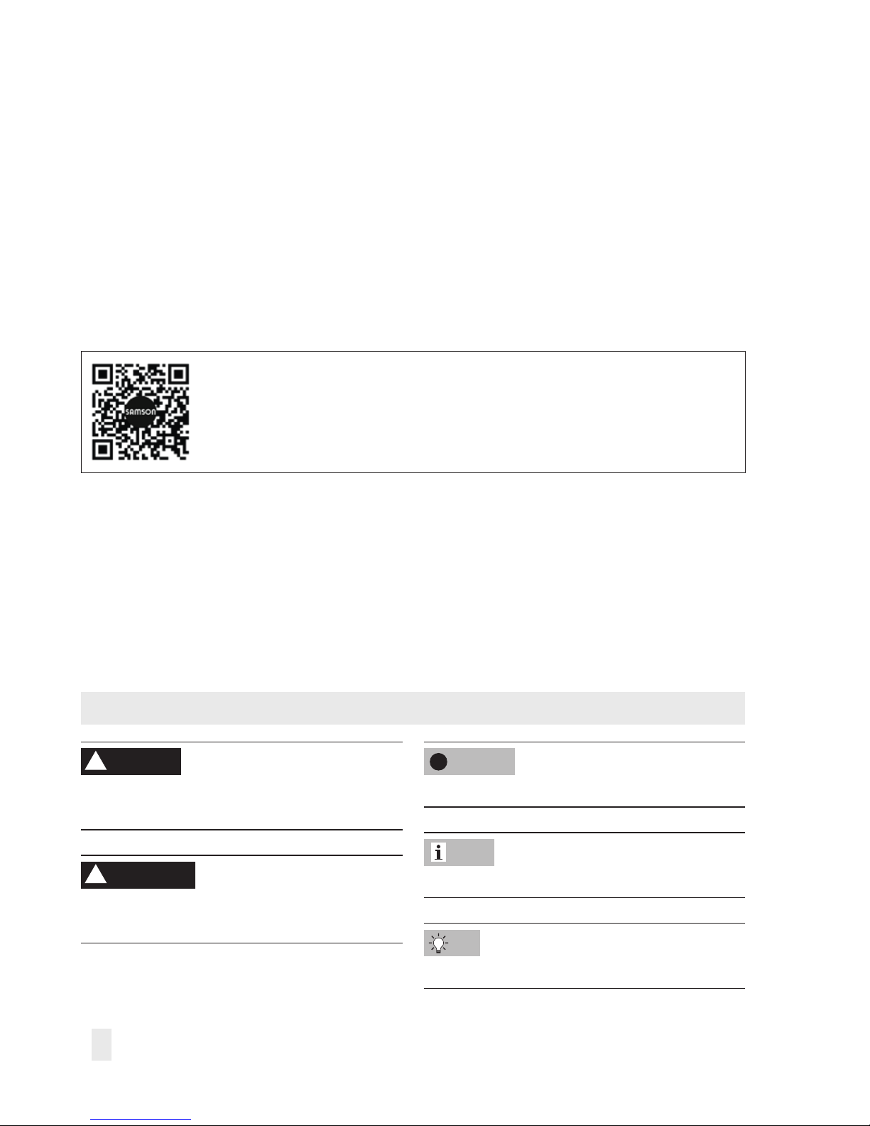
2 Markings on the control valve
2.1 Body inscription
SAMSON 3510
1 2
4
6
5
3
8
7
Fig.1: Body inscription
1 Valve size:
DIN: DN · ANSI: NPS· JIS: DN…A/B
2 Pressure rating:
DIN: PN · ANSI: CL · JIS: K
3 Flange/end connection type
4 Material
5 Order number and position number in the order
For after-sales service orders: AA prex
6 Heat number
7 Month and year associated with EAC symbol
8 PED (Pressure Equipment Directive), "Art. 4, Abs. 3"
ID of the notied body, uid group, and category
Page 11
EB 8091-1 EN 11
Markings on the control valve
The details on the valve version are lasered
onto the valve body (see Fig.1).
2.2 Actuator nameplate
See associated actuator documentation.
2.3 Material number
The valve are marked as follows:
Seat
− Material number
− SAMSON consecutive number
Plug
− Material number
− SAMSON consecutive number
− K
VS
coefcient and characteristic
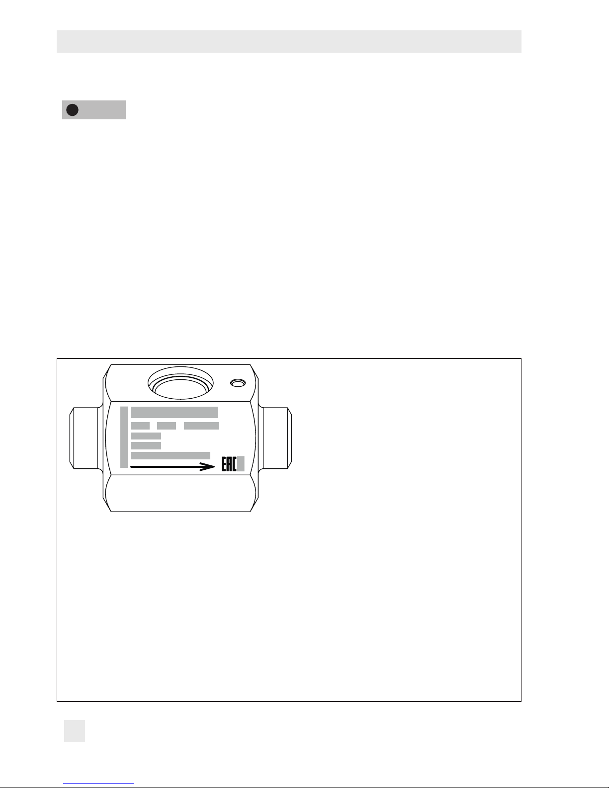
Anti-rotation xture (on the trim)
Î See Fig.2
− Plug material
− Seat material
− K
VS/CV
− Characteristic
− SAMSON consecutive number
Anti-rotation xture (on the bellows seal)
− Bellows material
− Nominal pressure
Incorrect control due to a combination of
trim parts that do not match each other.
The trim parts (seat, plug, anti-rotation xture, and body gasket) are matched to exactly t each other.
Only install matching trim parts.
1
2
3
4
Plug 1.4404
1.4404
0,025 lin
Seat
kvs
4 711
1 Plug material
2 Seat material
3 K
VS
coefcient and characteristic
4 Consecutive number
Fig.2: Anti-rotation xture (on the trim)
NOTICE
!
Page 12

12 EB 8091-1 EN
Design and principle of operation
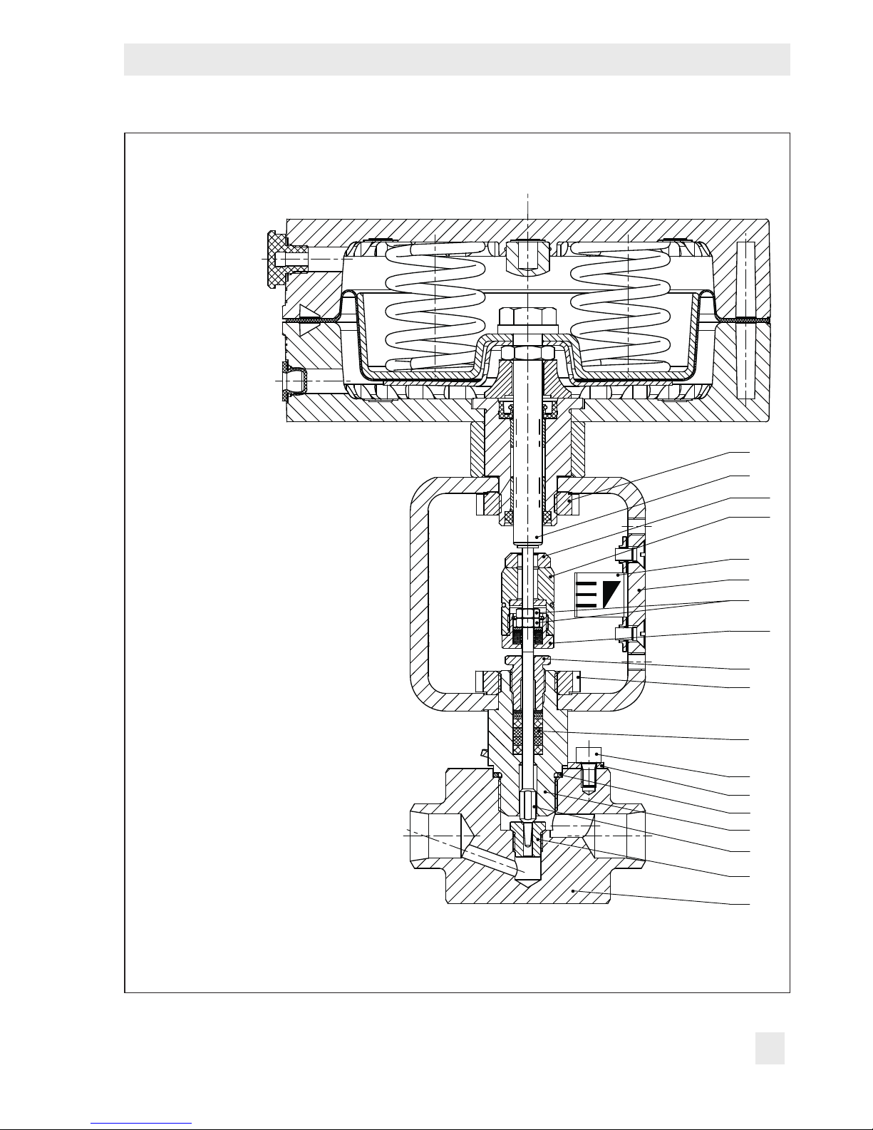
3 Design and principle of oper-
ation
The Type3510 Micro-ow Valve is available
as either a globe or angle valve and is preferably combined with a SAMSON
Type3271 or Type3277 Pneumatic Actuator
with 120cm² actuator area. It can also be
combined with other actuators.
The seat (2.2) and plug (2.1) are installed in
the body (1). The plug stem is connected to
the actuator stem (A7) by the stem connector
and is sealed by an adjustable packing with
PTFE seal rings (34).
The anti-rotation xture (2.4) prevents a
loosening of the screw connection between
the valve body and intermediate piece (4).
Two anti-rotation xtures are used for versions with an insulating section or bellows
seal: one anti-rotation xture between the
body and insulating section/bellows seal as
well as one anti-rotation xture between the
insulating section/bellows seal and intermediate piece.
The springs in the pneumatic actuator are located either above or below the diaphragm
depending on the selected fail-safe action
(see section3.1). A change in the signal
pressure acting on the diaphragm causes the
plug to move. The actuator size is determined by the diaphragm area.
The medium ows through the valve in the
direction indicated by the arrow. A rise in
signal pressure causes the force acting on
the diaphragm in the actuator to increase.
The springs are compressed. Depending on
the selected direction of action, the actuator
stem retracts or extends. As a result, the plug
position in the seat changes and determines
the ow rate through the valve.
3.1 Fail-safe positions
The fail-safe position depends on the actuator used.
Depending on how the compression springs
are arranged in the pneumatic actuator, the
valve has two different fail-safe positions:
Actuator stem extends (FA)
When the signal pressure is reduced or the
air supply fails, the springs move the actuator stem downward and close the valve. The
valve opens when the signal pressure is increased enough to overcome the force exerted by the springs.
Actuator stem retracts (FE)
When the signal pressure is reduced or the
air supply fails, the springs move the actuator stem upwards and open the valve. The
valve closes when the signal pressure is increased enough to overcome the force exerted by the springs.
The actuator's direction of action can be reversed, if required. Refer to the operating
and mounting instructions of the pneumatic
actuator, e.g. uEB8310-1 for Type3271
and Type3277 with 120cm² actuator area.
Tip
Page 13
EB 8091-1 EN 13
Design and principle of operation
1 Body
2.1 Plug with plug stem
2.2 Seat
2.3 Body gasket
2.4 Anti-rotation xture
4 Intermediate piece
6 Fillister head screw
11 Slotted round nut
12 Threaded bushing (packing
nut)
13 Yoke
14 Travel indicator scale
20 Hexagon nut
34 Packing
A7 Actuator stem
A8 Ring nut
A27.1 Stem connector nut
A27.2 Bearing sleeve (bottom part of
the stem connector)
A27.3 Lock nut
6
2.4
2.3
1
2.2
12
14
13
A8
A7
A27.3
A27.1
A27.2
4
34
11
20
2.1
Fig.3: Type3510 Micro-ow Valve as globe valve with Type3271 Pneumatic Actuator
Page 14
14 EB 8091-1 EN
Design and principle of operation
3.2 Versions
The modular design allows an insulating section or metal bellows to be tted to the standard valve version.
If valve accessories (e.g. positioner, limit
switch etc.) are to be mounted to the valve
version with anges, we recommend mounting an insulating section or bellows seal. This
provides more space to mount valve accessories.
Actuators
In these instructions, the preferable combination with a Type3271 or Type3277 Pneumatic Actuator is described. The pneumatic
actuator (with or without handwheel) can be
replaced by another pneumatic actuator in a
different size, but with the same travel.
Î Observe the maximum permissible actu-
ator force.
If the travel range of the actuator is larger
than the travel range of the valve, the spring
assembly in the actuator must be preloaded
so that the travel ranges match. See associated actuator documentation.
The basic pneumatic actuator can be replaced by a pneumatic actuator with additional handwheel or by an electric actuator.
3.3 Technical data
The nameplates on the valve and actuator
provide information on the control valve version. See section2.1 and the actuator documentation.
More information is available in Data Sheet
uT8091-1.
Compliance
The Type3510 Valve bears the EAC mark of
conformity:
Temperature range
Depending on the version, the control valve
is designed for a temperature range from 14
to 428°F (–10 to +220°C). The use of an
insulating section or bellows seal extends the
temperature range from –325 to +842°F
(–196 to +450°C). Special materials are
available for temperatures up to 1200°F
(650°C).
Leakage class
Depending on the version, the following
leakage class according to ANSI/FCI70-2
or IEC60534-4 applies:
− Leakage class IV with metal seal
− Leakage class V for high-performance
metal seal
Tip
Note
Note
Page 15

EB 8091-1 EN 15
Design and principle of operation
Noise emission
SAMSON is unable to make general statements about noise emission as it depends on
the valve version, plant facilities, and process
medium. On request, SAMSON can perform
calculations according to IEC60534,
Part8-3 and Part8-4 or VDMA24422 (edition 89).
Risk of hearing loss or deafness due to loud
noise.
Wear hearing protection when working near
the valve.
WARNING
!
Page 16

16 EB 8091-1 EN
Design and principle of operation
Dimensions and weights
Dimensions (in inch and mm) and weights (in lbs and kg)
The lengths and heights in the dimensional drawings are shown on p.18.
Dimensions and weights for Type3271 and Type3277 Pneumatic Actuators with 120cm²
actuator area can found in the Data Sheet uT8310-1.
Table1: Dimensions for Type3510 Valve
Connection
Female
thread
Welding ends Flanges
G/NPT/
Rc
1
/
8
to ¾
NPS½ NPS1 NPS½ NPS¾ NPS1
L
1)
Class 150
in
2.91”
74mm
7.25 7.25 7.25 7.25 7.25
mm 184 184 184 184 184
Class 300
in 7.50 7.75 7.50 7.62 7.75
mm 190 197 190 194 197
Class 600
in 8.00 8.25 8.00 8.12 8.25
mm 203 210 203 206 210
Class900/
Class1500
in 8.50 10.00 8.50 9.00 10.00
mm 216 254 216 229 254
Class 2500
in 10.38 12.12 10.38 10.75 12.12
mm 264 308 264 273 308
L1
1)
Class 150
in
1.33”
34mm
3.62 3.62 3.62 3.62 3.62
mm 92 92 92 92 92
Class 300
in 3.75 3.88 3.75 3.81 3.88
mm 95 99 95 97 99
Class 600
in 4.00 4.12 4.00 4.06 4.12
mm 101 105 101 103 105
Class900/
Class1500
in 4.25 5.00 4.25 4.50 5.00
mm 108 127 108 114 127
Class 2500
in 5.19 6.06 5.19 5.38 6.06
mm 132 154 132 137 154
Note
Page 17

EB 8091-1 EN 17
Design and principle of operation
Connection
Female
thread
Welding ends Flanges
G/NPT/
Rc
1
/
8
to ¾
NPS½ NPS1 NPS½ NPS¾ NPS1
H1 120cm²
in 4.80
mm 122
H4
Insulating section
up to Class 2500
10.35”/263mm
Bellows seal up to
Class 600
10.35”/263mm
Bellows seal up to
Class 1500
14.37”/365mm
H2 or
ange Ø
D1
Class 150
in
0.90”
2)
23mm
2)
0.90”
2)
23mm
2)
0.90”
2)
23mm
2)
3.54 3.94 4.33
mm 90 100 110
Class 300
in 3.74 4.53 4.91
mm 95 115 125
Class 600
in 3.74 4.53 4.91
mm 95 115 125
Class900/
Class1500
in 4.72 5.12 5.91
mm 120 130 150
Class 2500
in 5.31 5.51 6.30
mm 135 140 160
1)
Face-to-face dimensions of anges according to DINEN558
2)
H2= 1.10” (28mm) with body material B574 N06455
Page 18

18 EB 8091-1 EN
Design and principle of operation
Dimensional drawings
L
L1
SW50
57
SW46
L1
H4H2
H1
Type3510 as angle valve with
female thread
Type3510 as globe valve with
female thread, with bellows seal or insulat-
ing section
Page 19

EB 8091-1 EN 19
Design and principle of operation
Type 3510 · Valve body with
anges and welding ends
L
L
L1
L1
L1
L1
ØD1
ØD1
Table2: Weights for Type3510 Valve
Connection
Female
thread
Welding
ends
Flanges
G/NPT/Rc
1
/
8
to ¾
NPS½,
NPS1
NPS½ NPS¾ NPS1
Valve
without
actuator
Class150
lbs 3.74 4.0 5.8 7.3 8.2
kg 1.7 1.8 2.6 3.3 3.7
Class 300
lbs 3.74 4.0 7.1 9.3 10.6
kg 1.7 1.8 3.2 4.2 4.8
Class 600
lbs 3.74 4.0 7.5 10.6 11.5
kg 1.7 1.8 3.4 4.8 5.2
Class900/
Class1500
lbs 3.74 4.0 14.4 16.8 19.2
kg 1.7 1.8 5.2 7.6 8.7
Class 2500
lbs – – 14.4 20 21.7
kg – – 6.5 9.0 9.8
Optional
Insulating
section
lbs 1.2
kg 0.5
Bellows
seal
lbs 1.4
kg 0.6
Page 20

20 EB 8091-1 EN
Measures for preparation
4 Measures for preparation
After receiving the shipment, proceed as follows:
1. Check the scope of delivery. Compare
the shipment received against the delivery note.
2. Check the shipment for transportation
damage. Report any damage to SAMSON and the forwarding agent (refer to
delivery note).
4.1 Unpacking
Do not remove the packaging until immediately before installing the valve into the pipeline.
Proceed as follows to lift and install the
valve:
1. Remove the packaging from the valve.
2. Dispose of the packaging in accordance
with the valid regulations.
4.2 Transporting and lifting
SAMSON's After-sales Service department
can provide more detailed transport and lifting instructions on request.
4.2.1 Transporting
The control valve can be transported using
lifting equipment (e.g. crane or forklift).
Î Leave the control valve in its transport
container or on the pallet to transport it.
Î Observe the transport instructions.
Transport instructions
− Protect the control valve against external
inuences (e.g. impact).
− Do not damage the corrosion protection
(paint, surface coatings). Repair any
damage immediately.
− Protect the control valve against moisture
and dirt.
− The permissible transportation tempera-
ture of standard control valves is –4 to
+149°F (–20 to +65°C).
Contact SAMSON's After-sales Service department for the transportation temperatures
of other valve versions.
4.2.2 Lifting
Due to the low service weight, lifting equipment is not required to lift the control valve
(e.g. to install it into the pipeline).
Note
Tip
Information
Page 21

EB 8091-1 EN 21
Measures for preparation
4.3 Storage
Risk of valve damage due to improper storage.
− Observe storage instructions.
− Avoid long storage times.
− Contact SAMSON in case of different stor-
age conditions or long storage periods.
We recommend regularly checking the control valve and the prevailing storage conditions during long storage periods.
Storage instructions
− Protect the control valve against external
inuences (e.g. impact).
− Do not damage the corrosion protection
(paint, surface coatings). Repair any
damage immediately.
− Protect the control valve against moisture
and dirt. Store it at a relative humidity of
less than 75%. In damp spaces, prevent
condensation. If necessary, use a drying
agent or heating.
− Make sure that the ambient air is free of
acids or other corrosive media.
− The permissible storage temperature of
standard control valves is –4 to +149°F
(–20 to +65°C).
Contact SAMSON's After-sales Service department for the storage temperatures of other valve versions.
− Do not place any objects on the control
valve.
Special storage instructions for elastomers
Elastomer, e.g. actuator diaphragm
− To keep elastomers in shape and to pre-
vent cracking, do not bend them or hang
them up.
− We recommend a storage temperature of
59°F (15°C) for elastomers.
− Store elastomers away from lubricants,
chemicals, solutions, and fuels.
SAMSON's After-sales Service department
can provide more detailed storage instructions on request.
4.4 Preparation for installation
Proceed as follows:
Î Flush the pipelines.
The plant operator is responsible for cleaning the pipelines in the plant.
Î Check the valve to make sure it is clean.
Î Check the valve for damage.
NOTICE
!
Note
Information
Tip
Note
Page 22

22 EB 8091-1 EN
Measures for preparation
Î Check to make sure that the type desig-
nation, valve size, material, pressure rating and temperature range of the valve
match the plant conditions (size and
pressure rating of the pipeline, medium
temperature etc.).
Î For steam applications, make sure that
the pipelines are dry. Moisture will damage the inside of the valve.
Î Check any mounted pressure gauges to
make sure they function.
Î When the valve and actuator are al-
ready assembled, check the tightening
torques of the bolted joints (uAB0100).
Components may loosen during transport.
Page 23

EB 8091-1 EN 23
Mounting and start-up
5 Mounting and start-up
SAMSON valves are delivered ready for
use. In special cases, the valve and actuator
are delivered separately and must be assembled on site. The procedure to mount and
start up the valve are described in the following.
Risk of valve damage due to excessively high
or low tightening torques.
Observe the specied torques on tightening
control valve components. Excessively tightened torques lead to parts wearing out
quicker. Parts that are too loose may cause
leakage.
Observe the specied tightening torques
(uAB0100).
Risk of valve damage due to the use of unsuitable tools.
Only use tools approved by SAMSON
(uAB0100).
5.1 Mounting the actuator onto
the valve
Proceed as described in the actuator documentation if the valve and actuator have not
been assembled by SAMSON:
− Remove the mounted actuator before
mounting the other actuator (see associated actuator documentation).
− Preloading the actuator springs increases
the thrust of a pneumatic actuator and reduces the travel range of the actuator (see
associated actuator documentation).
5.2 Installing the valve into the
pipeline
5.2.1 Checking the installation
conditions
Pipeline routing
The inlet and outlet lengths vary depending
on the process medium. To ensure the control
valve functions properly, follow the installation instructions given below:
Î Observe the inlet and outlet lengths (see
Table3). Contact SAMSON if the valve
conditions or states of the medium process deviate.
Î Install the valve free of stress and with the
least amount of vibrations as possible. If
necessary, attach supports to the valve.
Î Install the valve allowing sufcient space
to remove the actuator and valve or to
perform service and repair work on
them.
NOTICE
!
NOTICE
!
Note
Page 24

24 EB 8091-1 EN
Mounting and start-up
Mounting position
Generally, we recommend installing the
valve with the actuator upright and on top of
the valve.
Vent plug
Vent plugs are screwed into the exhaust air
ports of pneumatic and electropneumatic devices. They ensure that any exhaust air that
forms can be vented to the atmosphere (to
avoid excess pressure in the device). Further-
more, the vent plugs allow air intake to prevent a vacuum from forming in the device.
Î Locate the vent plug on the opposite side
to the workplace of operating personnel.
Î On mounting valve accessories, make
sure that they can be operated from the
workplace of the operating personnel.
Table3: Inlet and outlet lengths
Q
a x DN b x DN
State of process
medium
Valve conditions
Inlet
length a
Outlet
length b
Gas
Ma≤0.3 2 4
0.3≤Ma≤0.7 2 10
Vapor
Ma≤0.3
1)
2 4
0.3≤Ma≤0.7
1)
2 10
Saturated steam (percentage of condensate >5%) 2 20
Liquid
Free of cavitation/w<10m/s 2 4
Cavitation producing noise/w≤3m/s 2 4
Cavitation producing noise/3<w<5m/s 2 10
Critical cavitation/w≤3m/s 2 10
Critical cavitation/3<w<5m/s 2 20
Flashing – 2 20
Multi-phase – 10 20
1)
No saturated steam
Q Flow rate
a Inlet length
b Outlet length
Page 25

EB 8091-1 EN 25
Mounting and start-up
The workplace of operating personnel is the
location from which the valve, actuator and
any mounted valve accessories can be accessed to operate them.
5.2.2 Additional ttings
Strainers
We recommend installing a SAMSON
strainer upstream of the valve. It prevents solid particles in the process medium from
damaging the valve.
Bypass and shut-off valves
We recommend installing a shut-off valve
both upstream of the strainer and downstream of the valve and setting up a bypass
line. The bypass ensures that the plant does
not need to be shut down for service and repair work on the valve.
Insulation
Only insulate control valves with insulating
section or bellows seal up to the bonnet
ange of the valve body for medium temperatures below 32°F (0°C) and above
428°F (220°C).
Do not insulate valves mounted to comply
with NACE MR0175 requirements.
Test connection
Versions with bellows seal tted with a test
connection (G
1
/
8
) at the top ange allow the
sealing ability of the bellows to be monitored.
Particularly for liquids and vapors as well as
explosive or hazardous substances, we recommend installing a suitable leakage indicator (e.g. a contact pressure gauge, an outlet
to an open vessel or an inspection glass).
Risk of personal injury due to pressurized
components and process medium escaping
under pressure.
Do not loosen the screw of the test connection while the valve is in operation.
Safety guard
To reduce the crush hazard arising from
moving parts (actuator and plug stem), a
safety guard can be installed.
Valve accessories
A mounting kit is required to mount positioners, limit switches, solenoid valves or other
valve accessories. The mounting kit (item no.
1400-9031) can be ordered from
SAMSON. Refer to the mounting and operating instructions of the corresponding device for a description on how to mount it.
5.2.3 Installing the control
valve
Version with female thread or anges
1. Close the shut-off valve in the pipeline
while the valve is being installed.
2. Remove the protective caps from the
valve ports before installing the valve.
Note
WARNING
!
Page 26

26 EB 8091-1 EN
Mounting and start-up
3. Lift the valve to the site of installation.
Observe the ow direction through the
valve. The arrow on the valve indicates
the direction of ow.
4. Make sure that the correct gaskets are
used on the end connections.
5. Bolt the pipe to the valve free of stress.
6. Depending on the eld of application,
allow the valve to cool down or heat up
to reach ambient temperature before
start up.
7. Slowly open the shut-off valve in the
pipeline after the valve has been installed.
Risk of valve damage due to a sudden pressure increase and resulting high ow velocities.
Slowly open the shut-off valve in the pipeline
during start-up.
8. Check the valve to ensure it functions
properly.
Version with welding ends
1. Proceed as described for Version with
female thread or anges (steps 1 to 3).
2. Completely retract the actuator stem to
protect the plug from sparks during welding.
3. Weld the valve free of stress into the
pipeline.
4. Proceed as described for Version with female thread or anges (steps 6 to 8).
5.3 Quick check
SAMSON valves are delivered ready for
use. To test the valve's ability to function, the
following quick checks can be performed:
Tight shut-off
1. Close the valve.
2. Slowly open the shut-off valve in the
pipeline.
Risk of valve damage due to a sudden pressure increase and resulting high ow velocities.
Slowly open the shut-off valve in the pipeline
during start-up.
3. Check the valve for leakage (visual inspection).
Travel motion
The movement of the actuator stem must be
linear and smooth.
Î Open and close the valve, observing the
movement of the actuator stem.
Î Apply the maximum and minimum con-
trol signals to check the end positions of
the valve.
Î Check the travel reading at the travel in-
dicator scale.
Fail-safe position
Î Shut off the signal pressure line.
Î Check whether the valve moves to the
fail-safe position.
NOTICE
!
NOTICE
!
Page 27

EB 8091-1 EN 27
Mounting and start-up
Adjustable packing
1. Tighten the threaded bushing gradually
(by turning it clockwise) until the packing
seals the valve.
Risk of valve damage due to the threaded
bushing tightened too far.
Make sure that the plug stem can still move
smoothly after the threaded bushing has
been tightened.
2. Open and close the valve several times.
3. Check the valve for leakage to the atmosphere (visual inspection).
4. Repeat steps 1 and 2 until the packing
completely seals the valve.
If the adjustable packing does not seal prop-
erly, contact SAMSON's After-sales Service
department.
Pressure test
During the pressure test, make sure the following conditions are met:
− Retract the plug stem to open the valve.
− Observe the maximum permissible pres-
sure for valve and plant.
The plant operator is responsible for performing the pressure test. SAMSON's After-sales Service department can support you
to plan and perform a pressure test for your
plant.
NOTICE
!
Note
Note
Page 28

28 EB 8091-1 EN
Operation
6 Operation
Immediately after completing mounting and
start-up (see section5), the valve is ready for
use.
Crush hazard arising from moving parts
(actuator and plug stem).
Do not insert hands or nger into the yoke
while the valve is in operation.
Risk of personal injury when the actuator
vents.
Wear eye protection when working in close
proximity to the control valve.
Risk of burn injuries due to hot or cold components and pipelines.
Depending on the process medium, valve
components, and pipelines may get very hot
or cold and cause burn injuries.
Wear protective clothing and safety gloves.
Operation disturbed by a blocked actuator
or plug stem.
Do not impede the movement of the actuator
or plug stem by inserting objects into their
path.
6.1 Working in manual mode
Valves tted with actuators with a handwheel
can be manually closed or opened in case of
supply air failure.
Î For normal closed-loop operation, move
the handwheel to the neutral position.
WARNING
!
WARNING
!
WARNING
!
NOTICE
!
Page 29

EB 8091-1 EN 29
Page 30

30 EB 8091-1 EN
Servicing
7 Servicing
The control valve is subject to normal wear,
especially at the seat, plug, and packing.
Depending on the operating conditions,
check the valve at regular intervals to prevent possible failure before it can occur.
SAMSON's After-sales Service department
can support you to draw up an inspection
plan for your plant.
We recommend removing the valve from the
pipeline for service or repair work (see section9.2).
Risk of bursting in pressure equipment.
Control valves and pipelines are pressure
equipment. Improper opening can lead to
bursting of the valve.
− Before starting any work on the control
valve, depressurize all plant sections con-
cerned as well as the valve.
− Drain the process medium from all the
plant sections concerned as well as the
valve.
− Wear personal protective equipment.
Risk of personal injury due to residual process medium in the valve.
While working on the valve, residual process
medium can escape and, depending on its
properties, may lead to personal injury, e.g.
(chemical) burns.
− If possible, drain any process medium resi-
dues from the plant sections concerned as
well as from the valve and dead cavities.
− Thoroughly ush the pipelines. The plant
operator is responsible for cleaning the
pipelines.
− Wear protective clothing, safety gloves,
and eyewear.
Risk of burn injuries due to hot or cold components and pipeline.
Valve components and the pipeline may become very hot or cold. Risk of burn injuries.
− Allow components and pipelines to cool
down or heat up.
− Wear protective clothing and safety gloves.
Risk of valve damage due to incorrect servicing or repair.
Service and repair work must only be
performed by trained staff.
Risk of valve damage due to excessively high
or low tightening torques.
Observe the specied torques on tightening
control valve components. Excessively tightened torques lead to parts wearing out
quicker. Parts that are too loose may cause
leakage.
Observe the specied tightening torques
(uAB0100).
Tip
DANGER
!
WARNING
!
WARNING
!
NOTICE
!
NOTICE
!
Page 31
EB 8091-1 EN 31
Servicing
Risk of valve damage due to the use of unsuitable tools.
Only use tools approved by SAMSON
(uAB0100).
Risk of valve damage due to the use of unsuitable lubricants.
Only use lubricants approved by SAMSON
(uAB0100).
The control valve was checked by SAMSON
before it left the factory.
− Certain test results (seat leakage and leak
test) certied by SAMSON lose their validity when the valve body or actuator hous-
ing is opened.
− The product warranty becomes void if ser-
vice or repair work not described in these
instructions is performed without prior
agreement by SAMSON's After-sales Ser-
vice department.
− Only use original spare parts by
SAMSON, which comply with the original
specications.
7.1 Replacing the gasket
7.1.1 Standard version
1. Remove the actuator from the valve. See
associated actuator documentation.
2. Loosen the slotted nut (11) at the valve.
Remove the yoke (13) from the intermediate piece (4).
3. Unscrew the llister head screw (6) on
the anti-rotation xture (2.4). Remove the
anti-rotation xture (2.4) from the intermediate piece (4).
4. Unscrew the intermediate piece (4) from
the body (1). Remove the intermediate
piece (4) together with plug (2.1) from
the body (1).
5. Remove gasket (2.3). Carefully clean the
sealing faces in the body (1) and on the
intermediate piece (4).
6. Insert a new gasket (2.3) into the body.
7. Apply a suitable lubricant to the thread
of the intermediate piece.
8. Place the intermediate piece (4) together
with the plug (2.1) onto the body. Use a
suitable tool to screw it into the body (1).
Observe tightening torques.
9. Push the anti-rotation xture (2.4) over
the intermediate piece (4) and lock it in
place with the llister head screw (6).
10. Place the yoke (13) onto the intermediate
piece (4) and secure with slotted nut
(11). Observe tightening torques.
11. Mount actuator. See associated actuator
documentation.
7.1.2 Version with insulating
section
1. Remove the actuator from the valve. See
associated actuator documentation.
NOTICE
!
NOTICE
!
Note
Page 32

32 EB 8091-1 EN
Servicing
1 Body
2.1 Plug with plug stem
2.2 Seat
2.3 Body gasket
2.4 Anti-rotation xture
4 Intermediate piece
6 Fillister head screw
11 Slotted round nut
12 Threaded bushing (packing
nut)
13 Yoke
14 Travel indicator scale
20 Hexagon nut
34 Packing
A7 Actuator stem
A8 Ring nut
A27.1 Stem connector nut
A27.2 Bearing sleeve (bottom part of
the stem connector)
A27.3 Lock nut
6
2.4
2.3
1
2.2
12
14
13
A8
A7
A27.3
A27.1
A27.2
4
34
11
20
2.1
Fig.4: Type3510 Micro-ow Valve as globe valve with Type3271 Pneumatic Actuator
Page 33

EB 8091-1 EN 33
Servicing
2. Loosen the slotted nut (11) at the valve.
Remove the yoke (13) from the intermediate piece (4).
3. Loosen the llister head screw (23) and
hexagon nut (26).
4. Remove the top section of the top anti-rotation xture (24.2) from the intermediate piece (4).
5. Unscrew the intermediate piece (4) out of
the insulating section (7) and carefully lift
it off the plug stem extension (22).
6. Remove the washer (27) from the insulating section (7).
7. Remove the bottom section of the top anti-rotation xture (24.2) from the insulating section (7).
8. Remove the seal (5). Carefully clean the
sealing faces in the intermediate piece
(4) and insulating section (7).
9. Loosen the llister head screw (6) on the
bottom anti-rotation xture (24.1). Remove the anti-rotation xture from the insulating section (7).
23
25
26
22
7
24.2
27
24.1
5
24.2
4
Fig.5: Type3510 with insulating section
Legend for Fig.5
4 Intermediate piece
5 Seal
7 Insulating section
22 Plug stem extension
23 Fillister head screw
24.1 Bottom anti-rotation xture
24.2 Top anti-rotation xture (two-piece)
25 Washer
26 Hexagon nut
27 Washer
Page 34

34 EB 8091-1 EN
Servicing
10. Unscrew the insulating section (7) from
the body (1). Remove the insulating section (7) together with the plug (2.1) and
plug stem extension (22) from the body
(1).
11. Remove gasket (2.3). Carefully clean the
sealing faces in the valve body (1) and
on the insulating section (7).
12. Insert a new gasket (2.3) into the body.
13. Apply a suitable lubricant to the thread
of the insulating section (7).
14. Place the insulating section (7) together
with the plug (2.1) and plug stem extension (22) onto the body. Use a suitable
tool to screw it into the body (1). Observe tightening torques.
15. Push the anti-rotation xture (24.1, with
'insulating section' inscribed on it) from
the top over the insulating section (7)
and lock it in place with the llister head
screw (6).
16. Push the bottom section of the top anti-rotation xture (24.2, without inscription) with its bent end facing downward
onto the insulating section (7).
17. Insert the new seal (5) into the insulating
section (7).
18. Place the washer (27) on the insulating
section (7).
19. Apply a suitable lubricant to the thread
of the intermediate piece (4).
20. Carefully place the intermediate piece (4)
over the plug stem extension (22) onto
the insulating section (7). Use a suitable
tool to screw it in. Observe tightening
torques.
It must be possible to turn the washer (27)
easily after the intermediate piece is fastened
tight. It must not be clamped down.
21. Push the top section of the top anti-rotation xture (24.2, with 'plug, seat' etc.
inscribed on it) with the bent end facing
upward over the intermediate piece (4).
22. Insert the llister head screw (23) through
both parts of the anti-rotation xture
(24.2). Push the washer (25) from below
onto the screw and lock in place with the
hexagon nut (26).
23. Place the yoke (13) onto the intermediate
piece (4) and secure with slotted nut
(11). Observe tightening torques.
24. Mount actuator. See associated actuator
documentation.
7.1.3 Version with bellows
seal
1. Remove the actuator from the valve. See
associated actuator documentation.
2. Loosen the slotted nut (11) at the valve.
Remove the yoke (13) from the intermediate piece (4).
3. Loosen the llister head screw (23) and
hexagon nut (26).
4. Remove the top section of the top anti-rotation xture (24.2) from the intermediate piece (4).
Note
Page 35

EB 8091-1 EN 35
Servicing
23
25
26
3.1
7
24.2
27
3.5
3.4
30
24.2
4
Fig.6: Type3510 with bellows seal and test
connection
5. Unscrew the intermediate piece (4) out of
the bellows seal (7) and carefully lift it off
the plug stem (3.1).
6. Remove the washer (27) from the bellows
seal (7).
7. Remove the bottom section of the top anti-rotation xture (24.2) from the bellows
seal (7).
8. Remove the seal (3.4). Carefully clean
the sealing faces in the intermediate
piece (4) and bellows seal (7).
9. Loosen the llister head screw (6) on the
bottom anti-rotation xture (3.5).
10. Version without test connection: remove
the anti-rotation xture (3.5) from the
bellows seal (7).
11. Unscrew the bellows seal (7) from the
body (1). Remove the bellows seal (7) including plug (2.1) from the body (1).
Version with test connection: pull the anti-rotation xture (3.5) downward to remove it.
Legend for Fig.6
3.1 Plug stem with bellows
3.4 Seal (on intermediate piece)
3.5 Bottom anti-rotation xture
4 Intermediate piece
7 Bellows seal
23 Fillister head screw
24.2 Top anti-rotation xture (two-piece)
25 Washer
26 Hexagon nut
27 Washer
30 Test connection
Page 36

36 EB 8091-1 EN
Servicing
12. Remove gasket (2.3). Carefully clean the
sealing faces in the valve body (1) and
on the bellows seal (7).
13. Insert a new gasket (2.3) into the body.
14. Apply a suitable lubricant to the thread
of the bellows seal (7).
15. Version with test connection: slide the
bottom anti-rotation xture (3.5, with
'bellows' inscribed on it) downward onto
the bellows seal (7).
The anti-rotation xture must be pushed onto
the bellows seal in such a way that its fasten-
ing hole is located directly over the threaded
hole in the body after the bellows seal is
bolted on.
16. Place the bellows seal (7) together with
the plug (2.1) onto the body. Use a suitable tool to screw it into the body (1).
Observe tightening torques.
Version without test connection: slide the
anti-rotation xture (3.5, with 'bellows'
inscribed on it) from the top over the bellows seal (7).
17. Lock the anti-rotation xture (3.5) in
place with the llister head screw (6).
18. Push the bottom section of the top anti-rotation xture (24.2, without inscription) with its bent end facing downward
onto the bellows seal (7).
19. Insert the new seal (3.4) into the bellows
seal (4).
20. Place the washer (27) on the bellows seal
(7).
21. Apply a suitable lubricant to the thread
of the intermediate piece (4).
22. Carefully place the intermediate piece (4)
over the plug stem (3.1) onto the bellows
seal (7). Use a suitable tool to screw it in.
Observe tightening torques.
It must be possible to turn the washer (27)
easily after the intermediate piece is fastened
tight. It must not be clamped down.
23. Push the top section of the top anti-rotation xture (24.2, with 'plug, seat' etc.
inscribed on it) with the bent end facing
upward over the intermediate piece (4).
24. Insert the llister head screw (23) through
both parts of the anti-rotation xture
(24.2). Push the washer (25) from below
onto the screw and lock in place with the
hexagon nut (26).
25. Place the yoke (13) onto the intermediate
piece (4) and secure with slotted nut
(11). Observe tightening torques.
26. Mount actuator. See associated actuator
documentation.
7.2 Replacing the packing
Risk of control valve damage due to incorrect
service or repair.
The packing can only be replaced when all
the following conditions are met:
− The valve does not have a bellows seal.
Note
Note
NOTICE
!
Page 37

EB 8091-1 EN 37
Servicing
To replace the packing in other valve ver-
sions, contact SAMSON's After-sales Service
department.
1. Remove the actuator from the valve. See
associated actuator documentation.
2. Loosen the slotted nut (11) at the valve.
Remove the yoke (13) from the intermediate piece (4).
3. Unscrew hex nuts (20) and remove the
stem connector parts.
4. Unscrew the threaded bushing (12).
5. Pull all the packing parts out of the packing chamber using a suitable tool.
6. Renew damaged parts. Clean the packing chamber thoroughly.
7. Apply a suitable lubricant to all the packing parts.
8. Carefully slide the packing parts over the
plug stem into the packing chamber using a suitable tool. Observe the proper
sequence (see Fig.7).
9. Screw in the threaded bushing (12) and
tighten it. Observe tightening torques.
10. Version without insulating section: place
the sleeve (A27.2) on the plug stem
(2.1).
Version with insulating section: place
the sleeve (A27.2) on the plug stem extension (22).
11. Thread on the hex nuts (20) and tighten
them. Observe tightening torques.
12. Place the yoke (13) onto the intermediate
piece (4) and secure with slotted nut
(11). Observe tightening torques.
13. Mount actuator. See associated actuator
documentation.
8 Seal (white)
9 Seal (black)
10 Packing washer
12 Threaded bushing
34 Packing
12
9
8
10
8
12
8
10
34
Fig.7: Adjustable packing: PTFE-compound and white PTFE seal rings (left) · White PTFE seal rings
(right)
Page 38

38 EB 8091-1 EN
Servicing
7.3 Replacing the seat and
plug
Risk of control valve damage due to incorrect
service or repair.
Seat and plug can only be replaced when all
the following conditions are met:
− The valve does not have a bellows seal.
To replace seat and plug in other valve ver-
sions, contact SAMSON's After-sales Service
department.
Incorrect control due to a combination of
trim parts that do not match each other.
The trim parts (seat, plug, anti-rotation xture, and body gasket) are matched to exactly t each other. The anti-rotation xture
must also be exchanged on replacing the
seat and plug. The trim parts are delivered
together and marked accordingly (see sec-
tion2.3).
Only install matching trim parts.
Risk of damage to the facing of the seat and
plug due to incorrect service or repair.
− Always replace both the seat and plug.
− Only install matching trim parts (see sec-
tion2.3).
7.3.1 Standard version
1. Remove the actuator from the valve. See
associated actuator documentation.
2. Loosen the slotted nut (11) at the valve.
Remove the yoke (13) from the intermediate piece (4).
3. Unscrew the llister head screw (6) on
the anti-rotation xture (2.4). Remove the
anti-rotation xture (2.4) from the intermediate piece (4).
4. Unscrew the intermediate piece (4) from
the body (1). Remove the intermediate
piece (4) together with plug (2.1) from
the body (1).
5. Replace gasket as described in section7.1.1.
6. Unscrew the hex nuts (20) from the plug
stem (2.1). Remove the stem connector
parts.
7. Unscrew the threaded bushing (12).
8. Replace the packing. See section7.2.
9. Unscrew the seat (2.2) using a suitable
tool.
10. Apply a suitable lubricant to the thread
and the sealing cone of the new seat.
11. Screw in the seat (2.2) using a suitable
tool. Observe tightening torques.
12. Pull the plug with plug stem (2.1) out of
the intermediate piece (4).
13. Apply a suitable lubricant to the new
plug stem (2.1) and thread of the intermediate piece (4).
14. Slide the new plug with plug stem (2.1)
into the intermediate piece (4).
NOTICE
!
NOTICE
!
NOTICE
!
Page 39

EB 8091-1 EN 39
Servicing
15. Place the intermediate piece (4) together
with the plug (2.1) onto the body. Use a
suitable tool to screw it into the body (1).
Observe tightening torques.
16. Push the anti-rotation xture (2.4) over
the intermediate piece (4) and lock it in
place with the llister head screw (6).
17. Place the yoke (13) onto the intermediate
piece (4) and secure with slotted nut
(11). Observe tightening torques.
18. Screw in the threaded bushing (12) and
tighten it. Observe tightening torques.
19. Place sleeve (A27.2) on the plug stem
(2.1).
20. Thread on the hex nuts (20) and tighten
them. Observe tightening torques.
21. Mount actuator. See associated actuator
documentation.
7.3.2 Version with insulating
section
1. Remove the actuator from the valve. See
associated actuator documentation.
2. Loosen the slotted nut (11) at the valve.
Remove the yoke (13) from the intermediate piece (4).
3. Loosen the llister head screw (23) and
hexagon nut (26).
4. Remove the top section of the top anti-rotation xture (24.2) from the intermediate piece (4).
5. Unscrew the intermediate piece (4) out of
the insulating section (7) and carefully lift
it off the plug stem extension (22).
6. Remove the washer (27) from the insulating section (7).
7. Remove the bottom section of the top anti-rotation xture (24.2) from the insulating section (7).
8. Replace the packing. See section7.2.
9. Replace seal as described in sec-
tion7.1.2.
10. Loosen the llister head screw (6) on the
bottom anti-rotation xture (24.1). Remove the anti-rotation xture from the insulating section (7).
11. Unscrew the insulating section (7) from
the body (1). Remove the insulating section (7) together with the plug (2.1) and
plug stem extension (22) from the body
(1).
12. Replace gasket as described in section7.1.2.
13. Unscrew the seat (2.2) using a suitable
tool.
14. Apply a suitable lubricant to the thread
and the sealing cone of the new seat.
15. Screw in the seat (2.2) using a suitable
tool. Observe tightening torques.
16. Unscrew the plug with plug stem (2.1)
from the plug stem extension (22) and
pull it out of the insulating section (7).
17. Apply a suitable lubricant to the end of
the plug stem of the new plug (2.1).
18. Slide the new plug with plug stem (2.1)
into the insulating section (7) and screw
it onto the plug stem extension (22). Observe tightening torques.
Page 40

40 EB 8091-1 EN
Servicing
19. Apply a suitable lubricant to the thread
of the insulating section (7).
20. Place the insulating section (7) together
with the plug (2.1) and plug stem extension (22) onto the body. Use a suitable
tool to screw it into the body (1). Observe tightening torques.
21. Push the anti-rotation xture (24.1, with
'insulating section' inscribed on it) from
the top over the insulating section (7)
and lock it in place with the llister head
screw (6).
22. Push the bottom section of the top anti-rotation xture (24.2, without inscription) with its bent end facing downward
onto the insulating section (7).
23. Place the washer (27) on the insulating
section (7).
24. Apply a suitable lubricant to the thread
of the intermediate piece (4).
25. Carefully place the intermediate piece (4)
over the plug stem extension (22) onto
the insulating section (7). Use a suitable
tool to screw it in. Observe tightening
torques.
It must be possible to turn the washer (27)
easily after the intermediate piece is fastened
tight. It must not be clamped down.
26. Push the top section of the top anti-rotation xture (24.2, with 'plug, seat' etc.
inscribed on it) with the bent end facing
upward over the intermediate piece (4).
27. Insert the llister head screw (23) through
both parts of the anti-rotation xture
(24.2). Push the washer (25) from below
onto the screw and lock in place with the
hexagon nut (26).
28. Place the yoke (13) onto the intermediate
piece (4) and secure with slotted nut
(11). Observe tightening torques.
29. Mount actuator. See associated actuator
documentation.
7.4 Preparation for return ship-
ment
Defective valves can be returned to
SAMSON for repair.
Proceed as follows to return valves to
SAMSON:
1. Put the control valve out of operation (see
section9).
2. Decontaminate the valve. Remove any
residual process medium.
3. Fill in the Declaration on Contamination,
which can be downloaded from our
website at uwww.samson.de > Services
> Check lists for after sales service >
Declaration on Contamination.
4. Send the valve together with the lled-in
form to your nearest SAMSON subsidiary. SAMSON subsidiaries are listed on
our website at uwww.samson.de >
Contact.
Note
Page 41

EB 8091-1 EN 41
Servicing
7.5 Ordering spare parts and
operating supplies
Contact your nearest SAMSON subsidiary
or the SAMSON After-sales Service department for information on spare parts, lubricants, and tools.
Spare parts
See section10.2 for details on spare parts.
Lubricant
Details on suitable lubricants can be found in
the document uAB0100.
Tools
Details on suitable tools can be found in the
document uAB0100.
Page 42
42 EB 8091-1 EN
Malfunctions
8 Malfunctions
Depending on the operating conditions, check the valve at certain intervals to prevent possible failure before it can occur. Operators are responsible for drawing up an inspection plan.
SAMSON's After-sales Service department can support you to draw up an inspection plan
for your plant.
8.1 Troubleshooting
Malfunction Possible reasons Recommended action
Actuator or plug stem does not
move on demand.
Actuator is blocked. Check attachment.
Unblock the actuator.
Signal pressure too low Check the signal pressure.
Check the signal pressure line for
leakage.
Actuator or plug stem does not
move through the whole range.
Signal pressure too low Check the signal pressure.
Check the signal pressure line for
leakage.
The valve leaks to the atmosphere (fugitive emissions).
The packing is defective. Replace packing (see sec-
tion7.2) or contact SAMSON's
After-sales Service department.
Packing tightened incorrectly. See section5.3, Adjustable
packing. Contact SAMSON's After-sales Service department
when it continues to leak.
Version with bellows seal: the
metal bellows seal is defective.
Contact SAMSON's After-sales
Service department.
Gasket worn out. Replace body gasket (see sec-
tion7.1) or contact SAMSON's
After-sales Service department.
Increased ow through closed
valve (seat leakage)
Dirt or other foreign particles deposited between the seat and
plug.
Shut off the section of the pipeline and ush the valve.
Valve trim, particularly with soft
seat, is worn.
Replace seat and plug (see section7.3 or contact SAMSON's
After-sales Service department).
Tip
Page 43

EB 8091-1 EN 43
Malfunctions
8.2 Emergency action
Upon supply air or control signal failure, the
valve moves to its fail-safe position (see section3.1).
The plant operator is responsible for emergency action to be taken in the plant.
In the event of a valve malfunction:
1. Close the shut-off valves upstream and
downstream of the control valve to stop
the process medium from owing
through the valve.
2. Check the valve for damage. If neces-
sary, contact SAMSON's After-sales Service department.
Putting the valve back into operation after
a malfunction
Î Slowly open the shut-off valves. Allow
the process medium to slowly ow into
the valve.
Contact SAMSON's After-sales Service department for malfunctions not listed in the table.
Note
Page 44

44 EB 8091-1 EN
Decommissioning and disassembly
9 Decommissioning and disas-
sembly
Risk of bursting in pressure equipment.
Control valves and pipelines are pressure
equipment. Improper opening can lead to
bursting of the valve.
− Before starting any work on the control
valve, depressurize all plant sections con-
cerned as well as the valve.
− Drain the process medium from all the
plant sections concerned as well as the
valve.
− Wear personal protective equipment.
Risk of personal injury due to residual process medium in the valve.
While working on the valve, residual process
medium can escape and, depending on its
properties, may lead to personal injury, e.g.
(chemical) burns.
− If possible, drain any process medium resi-
dues from the plant sections concerned as
well as from the valve and dead cavities.
− Thoroughly ush the pipelines. The plant
operator is responsible for cleaning the
pipelines.
− Wear protective clothing, safety gloves,
and eyewear.
Risk of burn injuries due to hot or cold components and pipeline.
Valve components and the pipeline may become very hot or cold. Risk of burn injuries.
− Allow components and pipelines to cool
down or heat up.
− Wear protective clothing and safety gloves.
9.1 Decommissioning
To decommission the control valve for service
and repair work or disassembly, proceed as
follows:
1. Close the shut-off valves upstream and
downstream of the control valve to stop
the process medium from owing
through the valve.
2. Completely drain the pipelines and
valve.
3. Disconnect and lock the pneumatic air
supply to depressurize the actuator.
4. If necessary, allow the pipeline and valve
components to cool down or heat up.
9.2 Removing the valve from
the pipeline
Version with female thread or anges
1. Put the control valve out of operation (see
section9.1).
DANGER
!
WARNING
!
WARNING
!
Page 45

EB 8091-1 EN 45
Appendix
2. Unfasten the valve or unbolt the ange
joint.
3. Remove the valve from the pipeline (see
section4.2).
Version with welding ends
1. Put the control valve out of operation (see
section9.1).
2. Cut the pipeline in front of the weld
seam.
3. Remove the valve from the pipeline (see
section4.2).
9.3 Removing the actuator
from the valve
See associated actuator documentation.
9.4 Disposal
Î Observe local, national, and internation-
al refuse regulations.
Î Do not dispose of components, lubri-
cants, and hazardous substances together with your other household waste.
10 Appendix
10.1 After-sales service
Contact SAMSON's After-sales Service department for support concerning service or
repair work or when malfunctions or defects
arise.
E-mail
You can reach the After-sales Service Department at aftersalesservice@samson.de.
Addresses of SAMSONAG and its subsidiaries
The addresses of SAMSON AG, its subsidiaries, representatives, and service facilities
worldwide can be found on the SAMSON
website, in all SAMSON product catalogs or
on the back of these Mounting and Operating Instructions.
Required specications
Please submit the following details:
− Order number and position number in
the order
− Type, model number, nominal size, and
valve version
− Consecutive number of installed trim
− Pressure, density, viscosity and tempera-
ture of the process medium
− Flow rate in cu.ft/min or m³/h
− Direction of ow
− Bench range of the actuator (e.g. 0.2 to
1bar)
− Is a strainer installed?
− Installation drawing
Page 46

46 EB 8091-1 EN
Appendix
10.2 Spare parts
1 Body
2 Trim
2.1 Plug with plug stem
2.2 Seat
2.3 Body gasket
2.4 Anti-rotation xture
3 Bellows (assembly)
3.1 Plug stem with bellows
3.2 Seal
3.3 Bellows nut
3.4 Seal (on intermediate piece)
3.5 Bottom anti-rotation xture
4 Intermediate piece
5 Seal
6 Fillister head screw
7 Bellows seal or insulating section
8 Seal
9 Seal
10 Packing washer
11 Slotted round nut
12 Threaded bushing (packing nut)
13 Yo ke
14 Travel indicator scale
15 Retaining plate
16 Countersunk screw
17 Bearing sleeve
18 Disk spring
19 Packing washer
20 Hexagon nut
21 Snap ring
22 Plug stem extension
23 Fillister head screw
24.1
Bottom anti-rotation xture
24.2
Top anti-rotation xture (two-piece)
25 Washer
26 Hexagon nut
27 Washer
29 Seal for test connection
30 Screw plug
32 Yoke (ready mounted)
34 Packing
37 Lower part of the stem connector
(assembly)
Trims (2.1 to 2.4) and metal bellows (3.1 to
3.5) are only available as spare parts as assemblies (2 and 3).
The seal rings (2.3 and 3.4) are also avail-
able separately.
Note
Page 47

EB 8091-1 EN 47
Appendix
Ch:
WNR
Ch. Nr.:
WNR
PN 400
SAMSON 3510
PN 400
Ch:
WNR
PN 400
Ch:
WNR
PN 400
Ch:
WNR
14
15
16
13
20
21
19
18
17
8
9
9
10
8
2.4
2.2
2.3
2.1
4
6
24.2
27
24.2
27
3.4
3.3
3.1
3.2
3.5
29
30
6
7
3
11
26
5
24.1
7
6
22
25
12
34
2
1
32
37
23
25
26
23
24.2
Page 48

SAMSON AG · MESS- UND REGELTECHNIK
Weismüllerstraße 3 · 60314 Frankfurt am Main, Germany
Phone: +49 69 4009-0 · Fax: +49 69 4009-1507
samson@samson.de · www.samson.de
EB 8091-1 EN
2017-05-16 · English
 Loading...