

Page 1
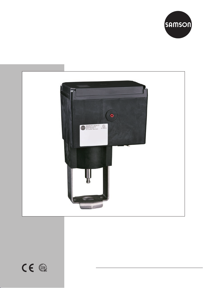
Type3374 Electric Actuator
Version with positioner, revision 3
Translation of original instructions
Mounting and
Operating Instructions
EB 8331-4 EN
Firmware version 3.11
Edition August 2016
Page 2
Note on these mounting and operating instructions
These mounting and operating instructions assist you in mounting and operating the device
safely. The instructions are binding for handling SAMSON devices.
Î For the safe and proper use of these instructions, read them carefully and keep them for
later reference.
Î If you have any questions about these instructions, contact SAMSON‘s After-sales Service
Department (aftersalesservice@samson.de).
The mounting and operating instructions for the devices are included in
the scope of delivery. The latest documentation is available on our website
(www.samson.de) > Product documentation. You can enter the document
number or type number in the [Find:] eld to look for a document.
Denition of signal words
!
DANGER
Hazardous situations which, if not avoided,
will result in death or serious injury
!
WARNING
Hazardous situations which, if not avoided,
could result in death or serious injury
2 EB 8331-4 EN
!
NOTICE
Property damage message or malfunction
Note
Additional information
Tip
Recommended action
Page 3

Contents
1 Safety instructions and measures ...................................................................6
1.1 Notes on possible severe personal injury .........................................................9
1.2 Notes on possible personal injury ...................................................................9
1.3 Notes on possible property damage ..............................................................10
2 Markings on the device ...............................................................................11
2.1 Nameplate ..................................................................................................11
3 Design and principle of operation ................................................................12
3.1 Versions ......................................................................................................12
3.2 Limit contacts ...............................................................................................13
3.2.1 Mechanical limit contacts ..............................................................................13
3.2.2 Electronic limit contacts .................................................................................13
3.3 Manual override ..........................................................................................13
3.3.1 Mechanical override ....................................................................................13
3.3.2 Moving the actuator stem manually ...............................................................13
3.4 Communication ...........................................................................................14
3.5 Device overview and operating controls .........................................................14
3.6 Technical data .............................................................................................16
3.7 Dimensions in mm ........................................................................................20
4 Measures for preparation ............................................................................22
4.1 Unpacking ..................................................................................................22
4.2 Transporting and lifting ................................................................................22
4.2.1 Transporting ................................................................................................22
4.2.2 Lifting ..........................................................................................................22
4.3 Storage .......................................................................................................22
5 Mounting and start-up .................................................................................23
5.1 Mounting the actuator onto the valve .............................................................23
5.1.1 Mounting position ........................................................................................23
5.1.2 Construction with integrated yoke ..................................................................24
5.1.3 Construction with ring nut .............................................................................24
5.2 Electrical connections ...................................................................................26
5.2.1 Connecting the power supply ........................................................................26
6 Additional functions ....................................................................................28
6.1 Mechanical limit contacts ..............................................................................28
6.1.1 Installing the limit contacts ............................................................................28
6.1.2 Adjusting the limit contacts ...........................................................................32
6.2 Electronic limit contacts .................................................................................32
6.2.1 Installing the limit contacts ............................................................................32
6.2.2 Adjusting the limit contacts ...........................................................................33
EB 8331-4 EN 3
Page 4

Contents
6.3 Setting up Modbus-RTU communication .........................................................34
6.3.1 Protocol .......................................................................................................34
7 Operation ...................................................................................................36
7.1 Display .......................................................................................................36
7.2 Rotary pushbutton .......................................................................................38
7.2.1 Menu control ...............................................................................................38
7.3 Serial interface ............................................................................................39
7.4 Optional key number protection ....................................................................40
7.4.1 Customized key number ...............................................................................41
8 Operating level ...........................................................................................42
8.1 Selecting the operating mode ........................................................................42
8.2 Adapting the display ....................................................................................43
8.2.1 Reading direction .........................................................................................43
8.2.2 Backlight .....................................................................................................43
8.3 Initializing the actuator .................................................................................44
8.4 Applications ................................................................................................45
8.4.1 Selecting the application ...............................................................................45
8.4.2 Terminal assignment depending on the application selected.............................47
9 Congurationlevel ......................................................................................50
9.1 Activating and setting parameters .................................................................50
9.2 Input signal .................................................................................................51
9.3 Operating direction ......................................................................................52
9.4 End position guiding ....................................................................................53
9.4.1 Operating direction increasing/increasing .....................................................53
9.4.2 Operating direction increasing/decreasing ....................................................54
9.5 Position feedback signal ...............................................................................54
9.6 Binary input ................................................................................................55
9.7 Binary output ............................................................................................... 56
9.8 Electronic limit contacts .................................................................................57
9.9 Restart ........................................................................................................57
9.10 Blockage .....................................................................................................58
9.11 Travel ..........................................................................................................59
9.12 Characteristic ..............................................................................................60
9.13 Fast conguration level .................................................................................62
9.14 Plausibility error ...........................................................................................64
10 Information level .........................................................................................66
10.1 Activating parameters ..................................................................................66
4 EB 8331-4 EN
Page 5

Contents
11 Service level ................................................................................................67
11.1 Activating and setting parameters .................................................................67
11.2 Starting zero calibration ...............................................................................68
11.3 Starting initialization ....................................................................................68
11.4 Restarting the actuator (reset) ........................................................................68
11.5 Loading default settings ................................................................................69
11.6 Testing the display ........................................................................................69
11.7 Measuring the transit time .............................................................................70
12 Communication level ...................................................................................70
12.1 Activating and setting parameters .................................................................71
13 Memory pen ...............................................................................................72
13.1 Command pen .............................................................................................73
14 Servicing.....................................................................................................75
14.1 Preparation for return shipment .....................................................................75
15 Malfunctions ...............................................................................................76
15.1 Error messages ............................................................................................76
15.2 Troubleshooting ...........................................................................................77
15.3 Emergency action ........................................................................................78
16 Decommissioning and disassembly ..............................................................79
16.1 Decommissioning .........................................................................................79
16.2 Removing the actuator from the valve ............................................................79
16.2.1 Construction with integrated yoke ..................................................................79
16.2.2 Construction with ring nut .............................................................................79
16.3 Disposal ......................................................................................................80
17 Annex.........................................................................................................81
17.1 After-sales service ........................................................................................81
17.2 Levels and parameters ..................................................................................82
17.2.1 Operating level ............................................................................................82
17.2.2 Conguration level .......................................................................................83
17.2.3 Characteristic level .......................................................................................87
17.2.4 Information level ..........................................................................................88
17.2.5 Service level ................................................................................................89
17.2.6 Communication level ....................................................................................91
17.2.7 Further codes on the display .........................................................................92
17.2.8 Excerpt from Modbus list ..............................................................................93
Index ..........................................................................................................98
EB 8331-4 EN 5
Page 6

Safety instructions and measures
Firmware revisions
Old New
3.10 3.11 (internal revisions)
1 Safety instructions and measures
The Type3374 Electric Actuator is designed to operate a mounted globe valve used in
industrial applications as well as in heating, ventilation and air-conditioning systems. The
digital positioner ensures a predetermined assignment of the valve position to the input
signal. The actuator is designed to operate under exactly dened conditions (e.g. thrust,
travel). Therefore, operators must ensure that the actuator is only used in applications that
meet the specications used for sizing the actuator at the ordering stage. In case operators
intend to use the actuator in other applications or conditions than specied, contact
SAMSON.
SAMSON does not assume any liability for damage resulting from the failure to use the de-
vice for its intended purpose or for damage caused by external forces or any other external
factors.
Î Refer to the technical data for limits and elds of application as well as possible uses. See
section3.6.
Reasonably foreseeable misuse
The actuator is not suitable for the following applications:
− Use outside the limits dened during sizing and by the technical data
Furthermore, the following activities do not comply with the intended use:
− Use of non-original spare parts
− Performing service and repair work not described in these instructions
Qualicationsofoperatingpersonnel
The actuator must be mounted, started up, serviced and repaired by fully trained and qualied personnel only; the accepted industry codes and practices are to be observed. According to these mounting and operating instructions, trained personnel refers to individuals who
are able to judge the work they are assigned to and recognize possible hazards due to their
specialized training, their knowledge and experience as well as their knowledge of the applicable standards.
6 EB 8331-4 EN
Page 7

Safety instructions and measures
Personal protective equipment
No personal protective equipment is required for the direct handling of the electric actuator.
Work on the control valve may be necessary when mounting or removing the electric actuator.
Î Observe the requirements for personal protective equipment specied in the valve docu-
mentation.
Î Check with the plant operator for details on further protective equipment.
Revisionsandothermodications
Revisions, conversions or other modications to the product are not authorized by SAMSON.
They are performed at the user's own risk and may lead to safety hazards, for example.
Furthermore, the product may no longer meet the requirements for its intended use.
Safety features
Upon power supply failure, the Type3374 Electric Actuator causes the valve to move to a
certain fail-safe position. The fail-safe action of SAMSON actuators is specied on the
actuator nameplate.
Warning against residual hazards
To avoid personal injury or property damage, plant operators and operating personnel must
prevent hazards that could be caused in the control valve by the process medium, the operating pressure, the signal pressure or by moving parts by taking appropriate precautions. They
must observe all hazard statements, warning and caution notes in these mounting and operating instructions, especially for installation, start-up and service work.
Responsibilities of the operator
The operator is responsible for proper operation and compliance with the safety regulations.
Operators are obliged to provide these mounting and operating instructions to the operating
personnel and to instruct them in proper operation. Furthermore, the operator must ensure
that operating personnel or third persons are not exposed to any danger.
EB 8331-4 EN 7
Page 8

Safety instructions and measures
Responsibilities of operating personnel
Operating personnel must read and understand these mounting and operating instructions as
well as the specied hazard statements, warning and caution notes. Furthermore, the operating personnel must be familiar with the applicable health, safety and accident prevention
regulations and comply with them.
Referenced standards and regulations
The Type3374 Electric Actuator fullls the requirements of the Directives 2014/30/EU and
2014/35/EU. The declaration of conformity includes information about the applied conformity assessment procedure. This declaration of conformity is included in the appendix of
these instructions.
The Type3374 Electric Actuator is designed for use in low voltage installations.
Î For wiring, maintenance and repair, observe the relevant safety regulations.
Referenced documentation
The following documents apply in addition to these mounting and operating instructions:
− Mounting and operating instructions of the valve on which the electric actuator is mount-
ed, e.g. for SAMSON valves:
uEB5861 for Type3260 Three-way Valve
uEB5868 for Type3213 and Type3214 Globe Valves
uEB8113 for Type3323 Three-way Valve
uEB8131 for Type3531 Globe Valve for Heat Transfer Oil
uEB8135 for Type3535 Three-way Valve for Heat Transfer Oil
8 EB 8331-4 EN
Page 9

Safety instructions and measures
1.1 Notes on possible severe personal injury
!
DANGER
Risk of electric shock.
Î Before connecting wiring, performing any work on the device or opening the de-
vice, disconnect the power supply and protect it against unintentional reconnection.
Î Only use power interruption devices that are protected against unintentional recon-
nection of the power supply.
Î Do not remove any covers to perform adjustment work on live parts.
Risk of bursting in pressure equipment.
Valves and pipelines are pressure equipment. Improper opening can lead to valve
components bursting.
Î Before starting any work on the valve, depressurize all plant sections concerned as
well as the valve.
Î Drain the process medium from all the plant sections concerned and from the valve.
Î Wear recommended personal protective equipment. See associated valve docu-
mentation.
1.2 Notes on possible personal injury
!
WARNING
Crush hazard arising from moving parts.
The electric actuator contains moving parts (actuator and plug stems), which can injure
hands or ngers if inserted into the actuator.
Î Do not insert hands or ngers into the yoke while the valve is in operation.
Î Disconnect the power supply before performing any work on the control valve.
Î Do not impede the movement of the actuator or plug stem by inserting objects into
their path.
EB 8331-4 EN 9
Page 10

Safety instructions and measures
1.3 Notes on possible property damage
!
NOTICE
Risk of damage to the electric actuator due to the power supply exceeding the
permissible tolerances.
The Type3374 Electric Actuator is designed for use according to regulations for
low-voltage installations.
Î Observe the permissible tolerances of the power supply.
Risk of actuator damage due to excessively high tightening torques.
Observe the specied torques on tightening the mounting parts of Type3374 Electric
Actuators. Excessively tightened torques lead to parts wearing out quicker.
Î Observe the specied tightening torques.
Risk of damage to the electric actuator due to incorrect operation of the manual
override.
The actuator stem of the electric actuator can be adjusted manually.
Î Do not operate the manual override while the actuator is running and only when the
power supply is disconnected.
Risk of actuator damage due to incorrect wiring of the binary inputs.
Î Always wire the binary inputs free of voltage.
10 EB 8331-4 EN
Page 11
2 Markings on the device
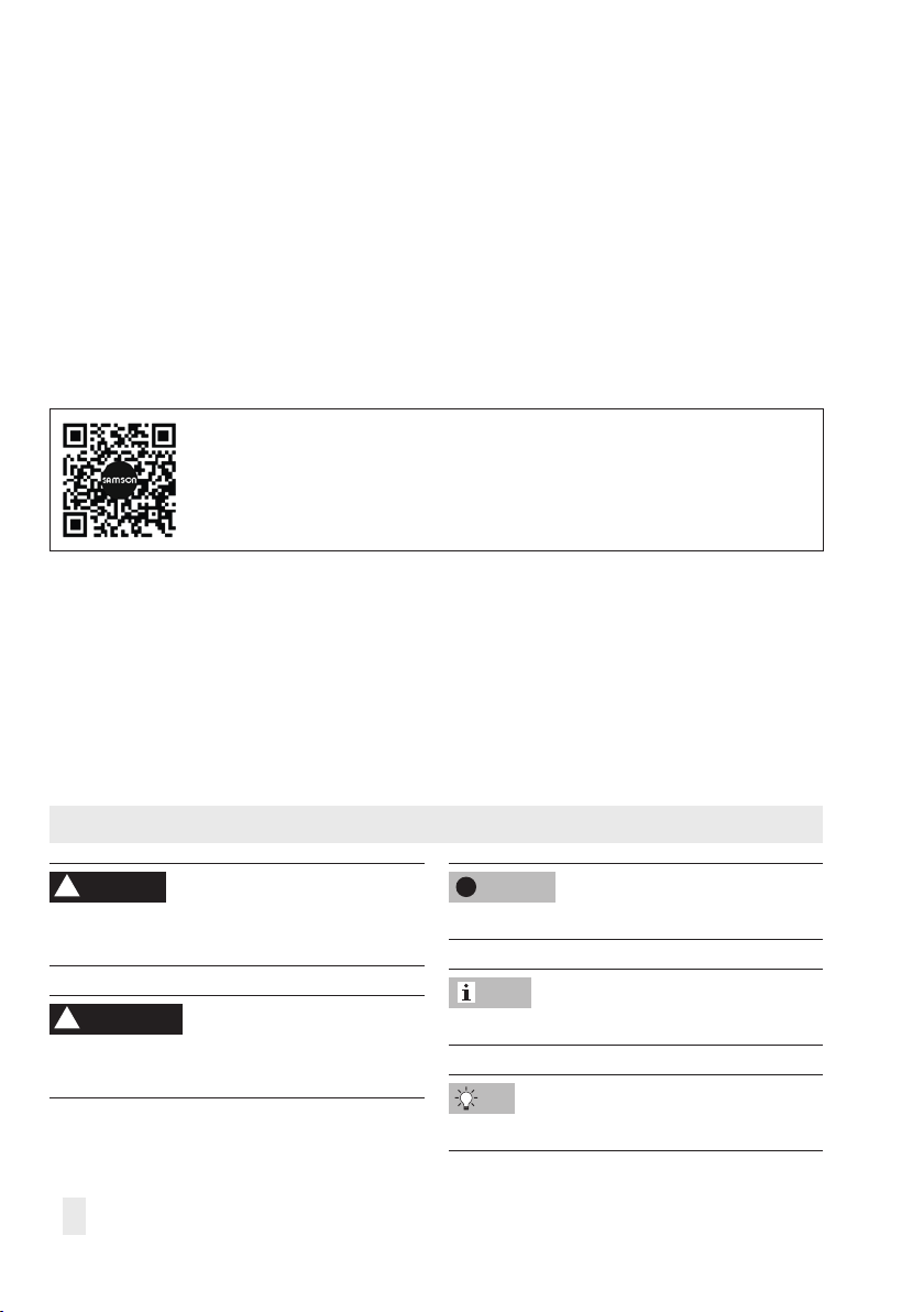
2.1 Nameplate
Markings on the device
SAMSON 3374-
Electric Actuator
Var. -ID
Serial no.
U:
max
:
P
s: v:
Digital Positioner
Firmware:
0(4) ... 20 mA DC; Ri = 50 Ω
0(2) ... 10 V DC; Ri = 20 kΩ
SAMSON AG, Germany
1 Type designation
2 Conguration ID
3 Serial number
4 Power supply; power line frequency
5 Power consumption
6 Nominal transit time
7 Stroking speed
8 Thrust (stem retracts)
9 Thrust (stem extends)
10 Fail-safe action
Retracts
4
5
6
11
2
3
F
7
or
F
13
Extends
1
8
9
12
Made in Germany
10
14
0062
11 Firmware version
12 Limit contacts
Mechanical limit contacts
Electronic limit contacts
13 Testing according to DINEN14597
14 Year
EB 8331-4 EN 11
Page 12
Design and principle of operation
3 Design and principle of oper-
ation
The Type3374 Electric Actuator is used in
industrial plants as well as in heating, ventilation and air-conditioning systems.
The actuator is suitable for form-t attachment to various SAMSON valve series, depending on the version with or without fail-
safe action.
The stepper motor is switched off by
torque-dependent switches in the end positions or in case of overload. The force of the
motor is transmitted to the actuator stem via
gearing and ball screw.
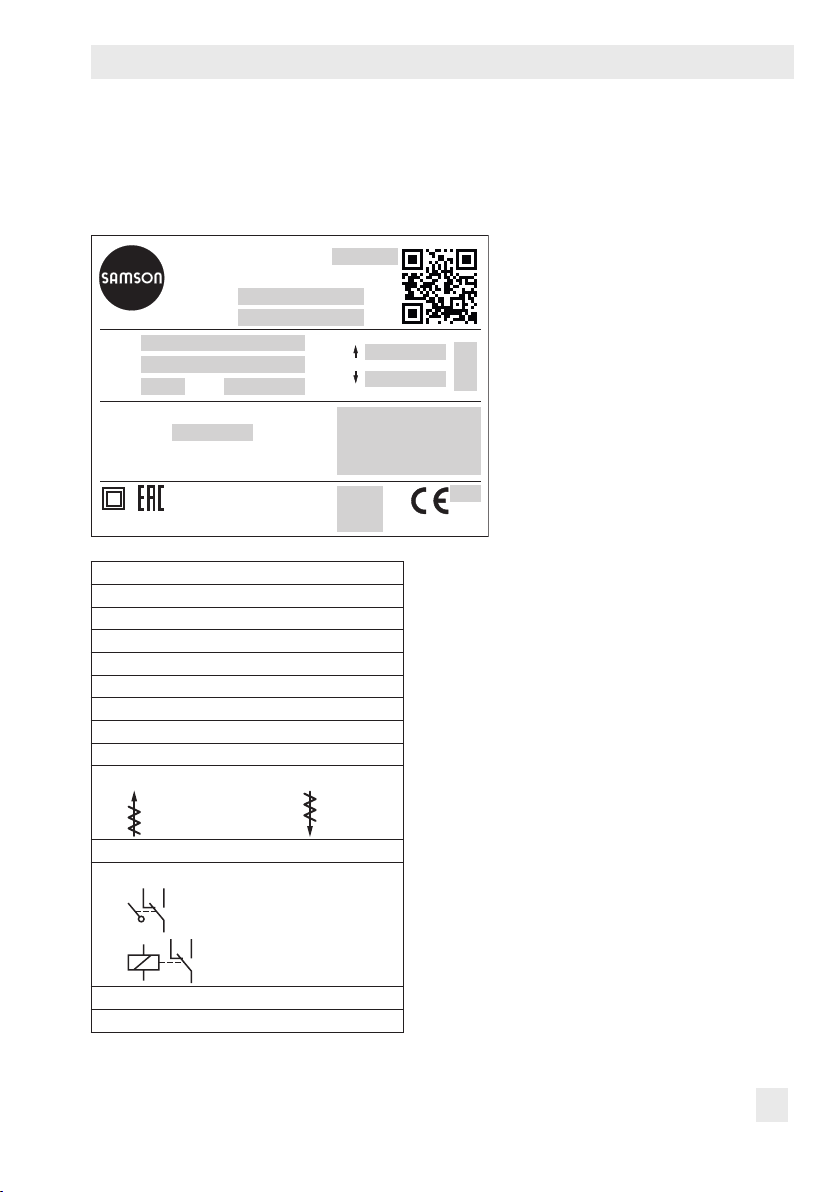
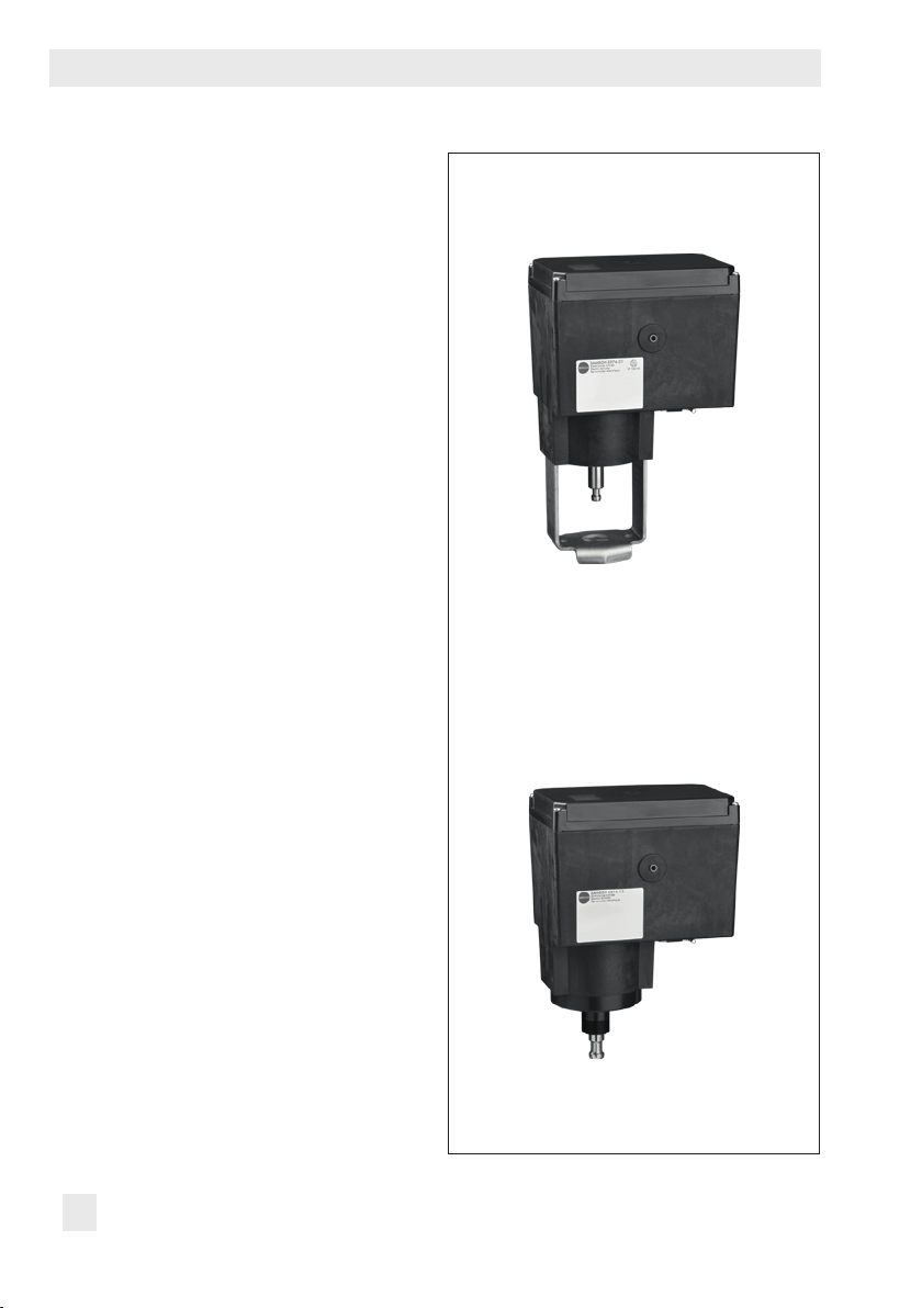
The Type3374 Actuator is optionally available with either integrated yoke (Fig.1) or
using an M30x1.5 ring nut (Fig.2) including
the necessary stem connecting parts.
TestingaccordingtoDINEN14597
The Types3374 Electric Actuator with fail-
safe action "actuator stem extends" is tested
by the German technical surveillance association (TÜV) according to DINEN14597 in
combination with various SAMSON valves.
The register number is available on request.
Fig.1: Construction with integrated yoke
3.1 Versions
The Type3374 Electric Actuator is available
with or without fail-safe action.
Version with fail-safe action
Type 3374-2x and Type 3374-3x Actuators
are able to perform a fail-safe action and
contain a spring assembly and an electromag
net. The actuator moves to the fail-safe position when the electromagnet is de-energized.
12 EB 8331-4 EN
-
Fig.2: Construction for mounting with ring nut
Page 13

Design and principle of operation
3.2 Limit contacts
The actuator can be equipped with either
mechanical or electronic limit contacts to in-
uence the tasks of control equipment.
3.2.1 Mechanical limit contacts
The two mechanical limit contacts can be adjusted independently from one another. They
are operated by mechanical pins. The instal
lation and adjustment of the mechanical limit
contacts is described in section6.1.
-
3.2.2 Electronic limit contacts
The two electronic limit contacts consist of relays with changeover contacts. In contrast to
the mechanical limit contacts, the electronic
limit contacts no longer function after a power
supply failure. The relays are de-energized
and the contacts change to the idle state. The
retrotting and adjustment of the electronic
limit contacts is described in section9.8.
3.3 Manual override
There are two ways to manually move the
actuator stem:
− Manual override with 4mm hex wrench
− MAN operating mode to move the actu-
ator stem manually
3.3.1 Mechanical override
The mechanical manual override is only possible for actuators without fail-safe action. It
is performed by placing a 4mm hex wrench
on the red actuator shaft located at the side
of the housing. The hex wrench is included in
the scope of delivery. It is attached to the
bottom of the housing.
Î Do not operate the manual override
while the actuator is running and only
when the power supply is disconnected.
3.3.2 Moving the actuator stem manually
First place the actuator into MAN mode to
move the actuator stem manually. The operation and selection of the operating mode
are described in section8.1 on page42.
EB 8331-4 EN 13
Page 14

Design and principle of operation
3.4 Communication
The Type3374 Electric Actuator has two
communication interfaces:
− Internal serial RS-232 interface for SSP
protocol for conguration using TROVIS-
VIEW.
Î See section7.3
− RS-485 interface (RS-485 module re-
quired) for Modbus-RTU protocol and
SSP protocol for conguration using
TROVIS-VIEW.
Î See section6.3
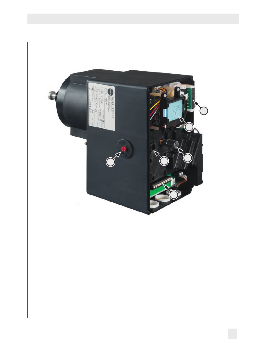
3.5 Device overview and operating controls
The operating controls are located underneath the housing cover.
Note
To undo the screws on the housing cover, use
a Pozidriv PZ2 screwdriver to get enough
hold on the screw heads.
14 EB 8331-4 EN
Page 15
Design and principle of operation
6
2
5
1 Rotary pushbutton
2 Display
3 Serial interface
4 Terminals
5 Actuating shaft for mechanical manual override
6 Terminal board for limit contacts
Fig.3: Operating controls (with housing cover removed)
3
1
4
EB 8331-4 EN 15
Page 16

Design and principle of operation
3.6 Technical data
Table1: Version without fail-safe action
Type3374 -10 -11 -15
Type of connection With yoke
Travel mm 30 15 30
Travel limitation Between 10 and 100% of the rated travel
Manual override 4mm hex wrench
Electrical connection
Power supply 24V(±15%), 47 to 63 Hz and 24VDC(±15%)
Power consumption Speedlevel:Normal·Fast
24V
AC 12.5 VA · 16.5 VA
DC 7.5 W · 11 W
85 to 264 V AC 13.8 to 20VA
Transittimeins·Strokingspeedinmm/s
Standard
version
Actuator
with faster
motor
Normal
Fast
Normal
Fast
3)
4)
3)
4)
120 · 0.25 60 · 0.25 120 · 0.25
60 · 0.5 30 · 0.5 60 · 0.5
60 · 0.5 30 · 0.5 60 · 0.5
30 · 1.0 15 · 1.0
ThrustinkN(Standardversion·Versionwithfastermotor)
Extends 2.5 · 1.25 2.5 · 1.25 2.5 · 1.25
Retracts 2.5 · 1.25 2.5 · 1.25 2.5 · 1.25
Weight
kg (approx.) 3.5 3.5 3.6
1)
For attachment to SAMSON Series V2001 Valves (DN 15 to 80) and to SAMSON Type3260
(DN65 to 150) and Type3214 Valves (DN65 to 100)
2)
For attachment to SAMSON Series240 Valves and to SAMSON Type3214 Valve (DN125 to 250)
3)
Normal speed level (Code c64 = NORM)
4)
Fast speed level (Code c64 = FAST)
1)
85 to 264V, 47 to 63Hz
With ring nut
30 · 1.0
2)
16 EB 8331-4 EN
Page 17

Design and principle of operation
Table2: Version with fail-safe action
Type3374 -21 -26 -31 -36
Type of connection With yoke
1)
With ring nut
Fail-safe action Extends Retracts
Travel mm 15 15
Travel limitation Between 10 and 100% of the rated travel
Manual override
Electrical connection
Power supply 24V(±15%), 47 to 63 Hz and 24VDC(±15%)
85 to 264V, 47 to 63Hz
Power consumption Speedlevel:Normal·Fast
24V
AC 18 VA · 23 VA
DC 11.5 W ·15 W
85 to 264 V AC 19.8 to 26VA
Transittimeins·Strokingspeedinmm/s
Normal
4)
Fast
3)
60 · 0.25 60 · 0.25 60 · 0.25 60 · 0.25
30 · 0.5 30 · 0.5 30 · 0.5 30 · 0.5
Upon fail-safe action 12 · 1.25 12 · 1.25 12 · 1.25 12 · 1.25
Forces in kN
Thrust (stem extends) 2 2 2 2
Thrust (stem retracts) 0.5 0.5 0.5 0.5
Nominal thrust of safety
spring
2 2 0.5
Weight
kg (approx.) 4.2 4.3 3.8 3.9
1)
For attachment to SAMSON Series V2001 Valves (DN 15 to 80) and to SAMSON Type3260
(DN65 to 150) and Type3214 Valves (DN65 to 100)
2)
For attachment to SAMSON Series240 Valves and to SAMSON Type3214 Valve (DN125 to 250)
3)
Normal speed level (Code c64 = NORM)
4)
Fast speed level (Code c64 = FAST)
2)
With yoke
–
1)
With ring nut
0.5
2)
EB 8331-4 EN 17
Page 18

Design and principle of operation
Table3: Common data
Digital positioner
Input signal
Position feedback
Binary input Open-circuit voltage: 10V; short-circuit current: 5mA
Binary output
Applications Positioner The travel follows the input signal
Display Icons for functions, codes and text eld with backlight
Rotary pushbutton Operating control for on-site operation to select and con-
Interface Standard RS-232 · For point-to-point connection to communication
Current input
Voltage input
Pt 1000 input
Binary input
0/4 to 20 mA, adjustable · Ri = 50 Ω
0/2 to 10 V, adjustable · Ri = 20 kΩ
1)
Measuring range: –50 to 150 °C, 300 µA
2)
By jumpering the terminals, not galvanically isolated
Current 0/4 to 20 mA, adjustable · Error message 24 mA
Resolution 1000 steps or 0.02mA
Load Max. 200 Ω
Voltage 0/2 to 10 V, adjustable · Error message 12 V
Resolution 1000 steps or 0.01V
Load Minimum 5 kΩ
By jumpering the terminals, not galvanically isolated
Floating, max. 230 V AC/1 A
PID controller Fixed set point control
Two-step mode Two-step behavior, control over binary input
Three-step mode Three-step behavior, control over binary input
Temperature closed-
loop control upon
The integrated PID controller uses a xed set point for
closed-loop control when the input signal is missing.
input signal failure
rm codes and values
participants or for memory pen · Permanently installed ·
Connection: RJ-12 connector socket
1)
For PID Controller (PID) and Temperature closed-loop control upon input signal failure (POSF)
applications only
2)
For two-step mode (2STP) and three-step mode (3STP) applications
18 EB 8331-4 EN
Page 19
Design and principle of operation
Safety
Motor switch-off By torque-dependent limit contacts
Degree of protection acc. to EN60529 IP54 with cable ducts
IP65 with cable glands (can be retrotted)
Suspended mounting not permitted according to
EN60664
Overvoltage category II according to EN61010
Design and testing According to EN61010
Class of protection II according to EN61140
EMC Acc. to EN61000-6-2, EN61000-6-3 and EN61326
Degree of contamination 2 according to EN61010
Noise immunity According to EN61000-6-2
Noise emission According to EN61000-6-3
Environmental conditions
Mechanical environmental conditions Class 1M2 according to EN60721-3-1:1998
Class 2M1 according to EN60721-3-2:1998
Class 3M4 according to EN60721-3-3:1998
Class 4M4 according to EN60721-3-4:1998
Permissible temperatures
2)
Ambient 5 to 60°C
Storage –25 to +70°C
Ambient conditions
Humidity 5 to 95% relative humidity, no dew formation
Compliance
·
1)
Additional electrical equipment
Limit contacts Mechanical
Two adjustable limit contacts with changeover switches;
230VAC/1A · Without contact protection
Electronic Two adjustable limit contacts with relay and changeover
switches;
230VAC/1A · Without contact protection
RS-485 module (order no. 1402-1522) Module for Modbus-RTU communication
1)
Cable glands M20x1.5 with metal nut SW 23/24 (order no. 1400-8828)
2)
The permissible medium temperature depends on the valve on which the electric actuator is
mounted. The limits in the valve documentation apply.
EB 8331-4 EN 19
Page 20
Design and principle of operation
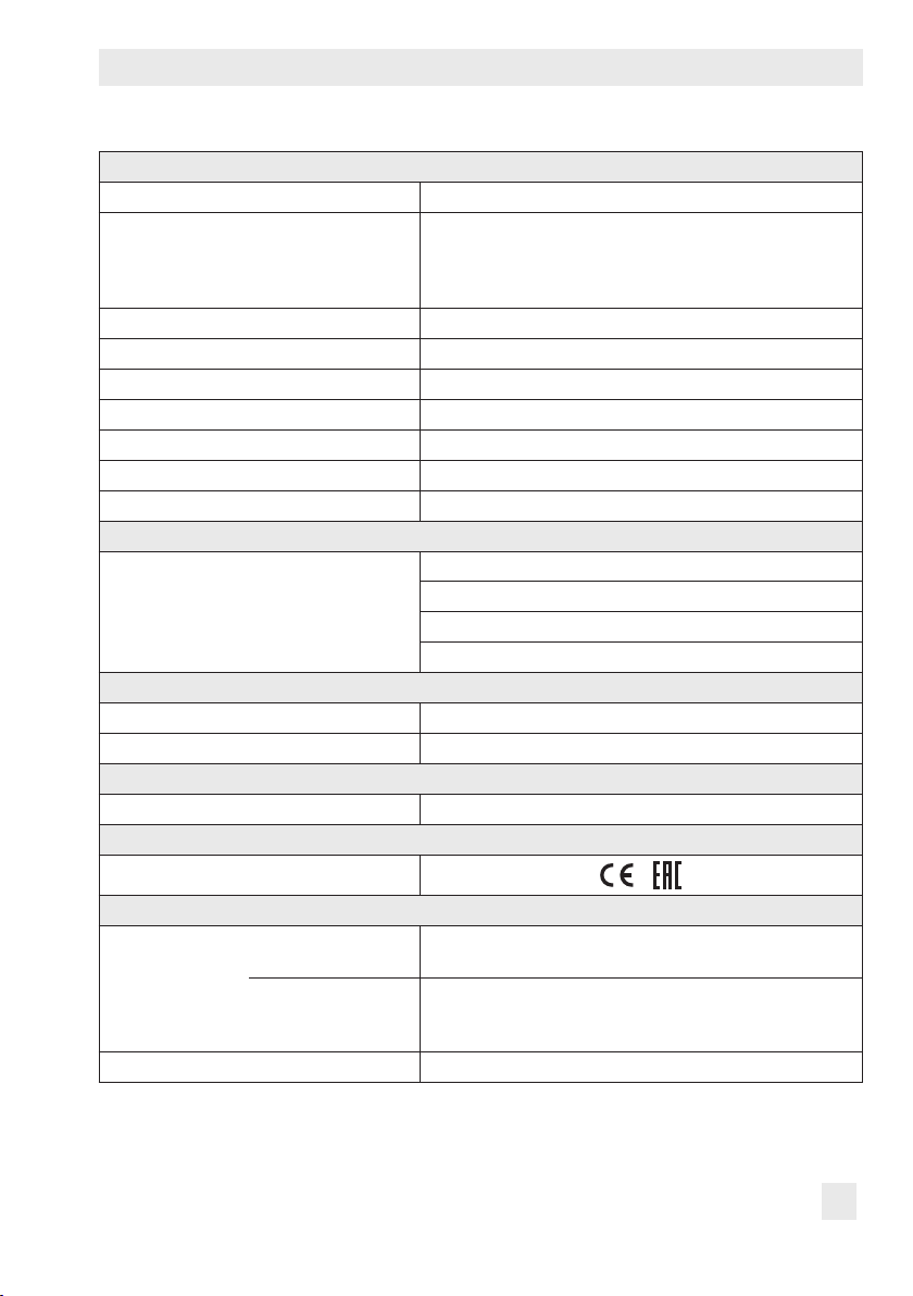
194
120
h
1
*
)
220
h
57
193
3.7 Dimensions in mm
Type3374-10/-11/-21/-31
120
57
298
h
)
50*
*) When actuator stem is fully extended
146
Type 3374 Dimension h
-10 30
-11 15
-21 15
-31 15
-15 30
-26 15
-36 15
20 EB 8331-4 EN
Page 21
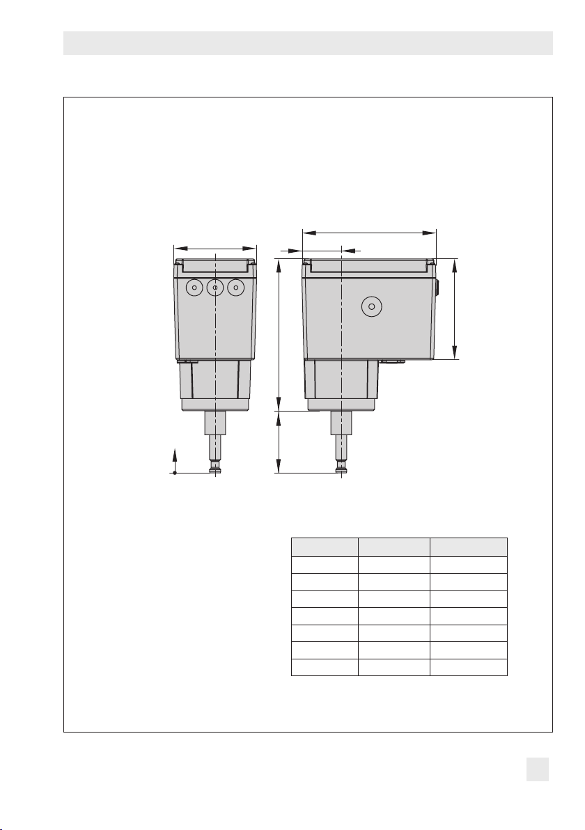
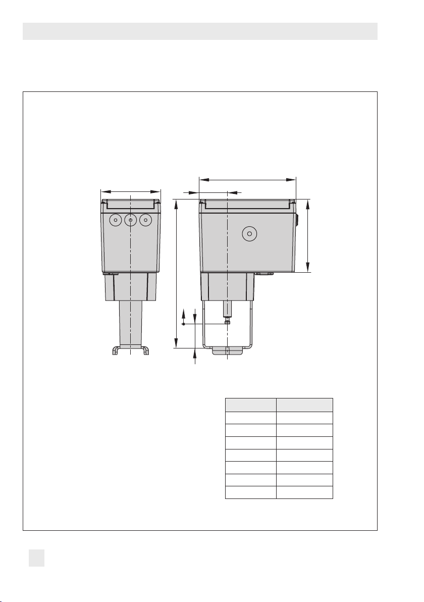
Types3374-15/-26/-36
193
Design and principle of operation
120
57
146
220
)
*
h
1
h
*) When actuator stem is fully extended
Type 3374 Dimension h Dimension h
-10 30 –
1
-11 15 –
-21 15 –
-31 15 –
-15 30 90
-26 15 75
-36 15 75
EB 8331-4 EN 21
Page 22

Measures for preparation
4 Measures for preparation
After receiving the shipment, proceed as follows:
1. Check the scope of delivery. Compare
the shipment received against the delivery note.
2. Check the shipment for transportation
damage. Report any damage to
SAMSON and the forwarding agent
(refer to delivery note).
4.1 Unpacking
Note
Do not remove the packaging until immediately before mounting and start-up.
1. Remove the packaging from the electric
actuator.
2. Dispose of the packaging in accordance
with the valid regulations.
4.2 Transporting and lifting
4.2.1 Transporting
− Protect the electric actuator against exter-
nal inuences (e.g. impact).
− Protect the electric actuator against mois-
ture and dirt.
− Observe the permissible transportation
temperature of –25 to +70°C.
4.2.2 Lifting
Due to the low service weight, lifting equipment is not required to lift the electric actuator.
4.3 Storage
!
NOTICE
Risk of electric actuator damage due to
improper storage.
− Observe storage instructions.
− Avoid long storage times.
− Contact SAMSON in case of different
storage conditions or long storage periods.
Note
We recommend regularly checking the electric actuator and the prevailing storage conditions during long storage periods.
Storage instructions
− Protect the electric actuator against exter-
nal inuences (e.g. impact).
− Protect the electric actuator against mois-
ture and dirt.
− Make sure that the ambient air is free of
acids or other corrosive media.
− Observe the permissible storage tem-
perature from –25 to +70°C.
− Do not place any objects on the electric
actuator.
22 EB 8331-4 EN
Page 23
Mounting and start-up
!
5 Mounting and start-up
!
NOTICE
Risk of malfunction due to incorrectly performed start-up.
Perform start-up following the described sequence.
1. Mount the actuator onto the valve.
Î See section5.1.
2. Connect power supply.
Î See section5.2.
3. Initialize the actuator.
Î See section8.3.
5.1 Mounting the actuator onto the valve
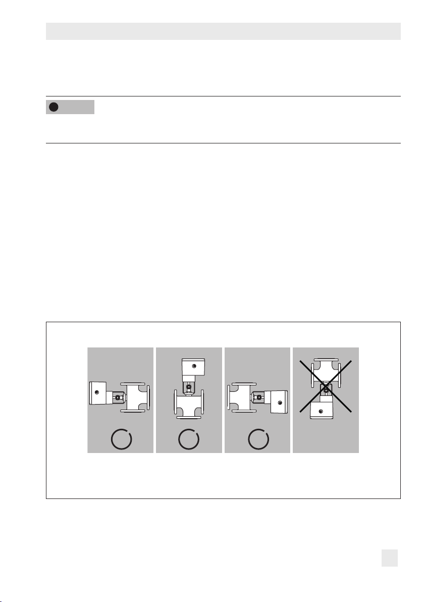
5.1.1 Mounting position
The control valve can be installed in the pipeline in any desired position. However, a suspended mounting position of the actuator is not permissible (see Fig.4).
Fig.4: Mounting position
EB 8331-4 EN 23
Page 24
Measures for preparation
2.1
5.1.2 Construction with integrated yoke
Attachment
− Series V2001 Valves (DN15 to 80)
− Type 3260 (DN65 to 150)
− Type3214 (DN65 to 100)
Î Refer to Fig.5
4. Remove protective covers and unscrew
nut (6) from the valve.
5. Connect the power supply to the actuator
as described in section5.2.
6. Retract actuator stem (3) as described in
section3.3.
7. Place actuator with yoke onto the valve
and fasten tight using nut (6, width
across ats 36) with a minimum tightening torque of 150Nm.
8. When the plug stem (5) ts closely onto
the actuator stem (3), attach both stem
connector clamps (4) and fasten with
screws.
5.1.3 Construction with ring nut
AttachmenttoSeries240Valves
Î See Fig.6 on page25.
1. Slide plug stem down to close the valve.
2. Turn the stem connector nut (8) until the
measurement x = 75mm (DN100 and
larger: x = 90 mm) from the top of the
yoke to the head of the stem connector
nut (8) is achieved. Lock this position
with the lock nut (9).
Types3374-10/-11/-21/-31
Connection with yoke
Attachment to Series V2001 Valves,
Type3260 (DN65 to 150),
Type3214 (DN65 to 100)
1
3
4
5
6
1 Actuator
2.1 Actuator yoke
2.2 Valve yoke
2.3 Bonnet
3 Actuator stem
4 Stem connector
5 Plug stem
6 Nut
7 Ring nut
8 Stem connector nut
9 Lock nut
10 Travel indicator scale
Fig.5: Attachment to Series V2001 Valves
24 EB 8331-4 EN
Page 25

Measures for preparation
2.3
10
2.2
3. Connect the power supply as described
in section5.2.
4. Retract actuator stem (3) as described in
section3.3.
5. Place actuator onto the valve bonnet
(2.3) and secure using the ring nut (7).
6. When the stem connector nut (8) rests on
the actuator stem, attach both stem connector clamps (4) and fasten with screws.
Move actuator stem (3) to the end posi-
tion (valve closed) as described in sec-
tion3.3.
7. Align travel indicator scale (10) with the
middle of the stem connector (4) and
screw tight.
AttachmenttoType3214Valve(DN125to
250)
Î Refer to Fig.7
1. Connect the power supply as described
in section5.2.
2. Retract actuator stem (3) as described in
section3.3.
3. Place actuator onto the valve and secure
using the ring nut (7). If necessary, retract the actuator stem slightly beforehand.
4. When the plug stem ts closely onto the
actuator stem (3), attach both stem connector clamps (4) and fasten with screws.
Move actuator stem (3) to the end posi-
tion (valve closed) as described in sec-
tion3.3.
5. Align travel indicator scale (10) with the
middle of the stem connector (4) and
screw tight.
Types3374-15/-26/-36
Connection with ring nut
Attachment to Series240 Valves
1
7
3
4
8
9
5
Fig.6: Attachment to Series240 Valves
Types3374-15/-26/-36
Connection with ring nut
Attachment to Type3214 Valve (DN125 to
250)
1
7
3
10
4
5
Fig.7: Attachment to Type3214
x
EB 8331-4 EN 25
Page 26

Measures for preparation
5.2 Electrical connections
!
DANGER
Risk of electric shock.
− Upon installation of the electric cables, you
are required to observe the regulations
concerning low-voltage installations ac-
cording to DINVDE0100 as well as the
regulations of your local power supplier.
− Use a suitable power supply which guar-
antees that no dangerous voltages reach
the device in normal operation or in the
event of a fault in the system or any other
system parts.
− Connect the actuator to the electrical net-
work only after the power supply is rst
switched off. Make sure the power cannot
be switched on unintentionally.
!
NOTICE
Risk of actuator damage due to incorrect
wiring of the binary inputs.
Always wire the binary inputs free of voltage.
Î Connect binary signals over oating con-
tacts.
Note
After connecting the power supply
ing up the actuator for the rst time, the start
screen and the error reading E00 "RUNT"
(no initialization performed) appear in alter-
nating sequence (see Fig.13 on
page36).
on start-
5.2.1 Connecting the power supply
Î Connect the wiring as shown in Fig.8.
Additionally, the terminal assignment depends on the selected application (see
section8.4 on page45 and section8.4.2 on page47).
Î Guide the cables to the spring-cage ter-
minals from the top.
26 EB 8331-4 EN
Page 27

Measures for preparation
+OUT I
41 44 42 51 54 52
41 44 42 51 54 52
0/4 to 20mA
–OUT U/I
0/2 to 10V
+OUT U
+1 IN
–1 IN
+2IN
Inputs 1 to 4
–2IN
(see section8.4.2 for assignment)
+3IN
–3IN
+4IN
4IN
–
Position feedback
OUT B –
OUT B +
Binary output
L
Power supply
N
(depending on version 24VAC and DC; 85 to 264VAC)
Options:
Mechanical limit contacts Electronic limit contacts
41 44 42 51 54 52
Table4: Cables and stranded wires that can be used
Cable Cross section
Single-wire H05(07) V-U
Fine-wire H05(07) V-K
1)
1)
With wire ferrule acc. to DIN46228-1 0.25 to 1.5mm²
With wire ferrule and sleeve acc. to DIN46228-4 0.25 to 0.75mm²
1)
8mm stripped insulation at cable end
0.2 to 1.5mm²
0.2 to 1.5mm²
Fig.8: Electrical connection
EB 8331-4 EN 27
Page 28

Additional functions
6 Additional functions
6.1 Mechanical limit contacts
6.1.1 Installing the limit contacts
Î When ordering the limit contacts, state the conguration ID and the type designation of
the actuator. Both specications are written on the nameplate (see section2.1).
Î Required accessories (see Fig.9):
To install the electronic limit contacts, the retrot kit (order no. 1402-0898) is required.
Installinglimitcontacts(Fig.10toFig.12):
!
DANGER
Risk of electric shock.
Before installing electrical accessories, switch off the power supply and disconnect the signal
input.
Tip
We recommend applying a small amount of lubricant (e.g. Vaseline) to the spindles on the
gear faces and to the sides of the cogs.
Note
To undo the screws on the housing cover, use a Pozidriv PZ2 screwdriver to get enough hold
on the screw heads.
28 EB 8331-4 EN
Page 29
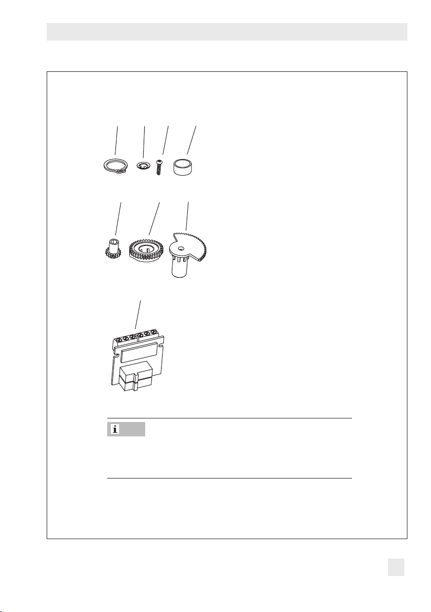
9 (2x) 16 (2x)3 8
Additional functions
18 (2x) 19 (2x)
17
20
3 Serrated ring
8 Spacer
9 Snap ring
16 Screw
17 Terminal board
18 Adjustment gear
19 Contact cam
20 Cam holder
Note
The contact cams (19) are ready-mounted to the cam holder
(20) and the retaining rings (9) to form the contact cam unit
(21, see Fig.12).
Fig.9: Accessories (order no. 1402-0898)
EB 8331-4 EN 29
Page 30
Additional functions
18 21 1
18 21 1
1. Undo screws on housing cover and take
the cover off the actuator.
2. Move the actuator stem to the end position
depending on the fail-safe action "actua
tor stem extends" or "actuator stem re-
tracts” (see section3.3).
3. Remove serrated ring and shim from spin
dle (11).
4. Slide adjustment gears (18) onto their
spindles and fasten with one screw (16)
each. Check whether the adjustment gears
can be turned easily. If not, slightly loosen
its screw again.
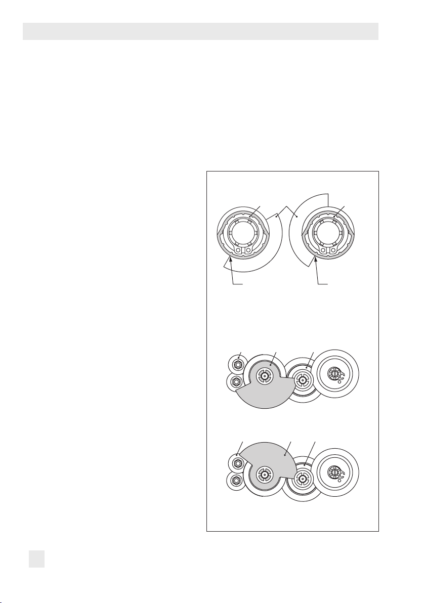
5. Turn contact cams (19) on the cam holder
(20) as illustrated in Fig.10 correspond
ing with the position of the actuator stem.
6. Slide the spacer (8) onto the spindle (11).
Make sure that the long wire of the tension
spring rests on the spacer and on the in
termediate gear.
7. Slide the contact cam unit (21) onto the
spindle corresponding with the position of
the actuator stem as illustrated in Fig.11.
Make sure that the outermost cog of the
contact cam unit engages in the gear
wheel of the intermediate gear (1). In addition, the adjustment gears (18) must engage properly in the corresponding gears
of the contact cam unit (21).
8. Secure the contact cam unit (21) and in-
termediate gear (1) with the serrated ring
(3); push down the serrated ring as far as
it will go.
9. Position the terminal board (17) at the
base of the support at a 45° angle (ap
prox.) with the switches pointing towards
the gears. Swivel the upper end of the terminal board towards the gears until the
board is in a vertical position and proper
-
ly engaged in the support.
10. Adjust limit contacts as described in sec
-
-
tion6.1.2.
-
19 1920
-
Actuator stem
retracted
-
Fig.10:
Alignment of contact cam and cam holder
Actuator stem
extended
B
-
When actuator stem retracted
B
-
Fig.11:Alignment of the contact cam unit
When actuator stem extended
30 EB 8331-4 EN
Page 31

Additional functions
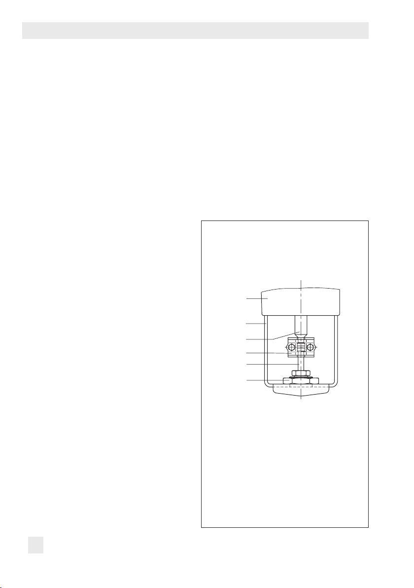
11
18
8
4
1 Intermediate gear
2 Spindle gear
3 Serrated ring
4 Tension spring
8 Spacer
11 Spindle
12 Actuator board
13 Bearing sleeve
17 Terminal board
18 Adjustment gear
21 Contact cam unit
17 21
Stateondelivery:
Spindle (11) with serrated
ring and shim
1 23
12
13
Fig.12:Installing the limit contacts
EB 8331-4 EN 31
Page 32

Additional functions
11. Replace cover. Briey turn the fastening
screws counterclockwise with a screwdriver to center them. Then fasten down
the cover by tightening the screws.
6.1.2 Adjusting the limit contacts
Note
To undo the screws on the housing cover, use
a Pozidriv PZ2 screwdriver to get enough
hold on the screw heads.
1. Undo screws on housing cover and take
the cover off the actuator.
2. Switch on power supply.
3. Move the valve, using manual override
or the "manual level" operating mode, to
the point at which the contact should react.
4. Use a 4mm hex wrench to turn the spin-
dle of the adjustment gears (18) for the
upper limit contact or for the lower limit
contact until the associated contact cam
(19) of the contact cam unit (21) triggers
the switch contact of the upper or lower
microswitch on the terminal board (17).
5. Replace cover. Briey turn the fastening
screws counterclockwise with a screwdriver to center them. Then fasten down
the cover by tightening the screws.
6.2 Electronic limit contacts
6.2.1 Installing the limit contacts
Required accessories
To install the electronic limit contacts, the retrot kit (order no. 1402-0591) is required.
Installinglimitcontacts:
!
DANGER
Risk of electric shock.
Before installing electrical accessories, switch
off the power supply and disconnect the signal input.
Note
To undo the screws on the housing cover, use
a Pozidriv PZ2 screwdriver to get enough
hold on the screw heads.
1. Undo screws on housing cover and take
the cover off the actuator.
2. Connect connecting cable to the plug-in
location intended for it on the board.
3. Position the terminal board (17, see
Fig.12) at the base of the support at a
45° angle (approx.) with the relay pointing towards the edge of the intermediate
board. Swivel the upper end of the terminal board until the board is properly engaged.
4. Replace cover. Briey turn the fastening
screws counterclockwise with a screw-
32 EB 8331-4 EN
Page 33

driver to center them. Then fasten down
the cover by tightening the screws.
6.2.2 Adjusting the limit contacts
The electronic limit contacts are adjusted at
the operating controls of the actuator (see
section 3.5). See section 9.8 on how to adjust them.
Additional functions
EB 8331-4 EN 33
Page 34

Additional functions
6.3 Setting up Modbus-RTU communication
The electric actuator can be connected to a
control station over Modbus and can be con-
gured using TROVIS-VIEW. For this purpose, the actuator with rmware version
3.10 and higher can be tted with an RS-
485 module. Various communications protocol (SSP or Modbus-RTU slave) are used for
various functions.
For Modbus-RTU communication, the RS-485
module (order no. 1402-1522) must be inserted into the actuator.
Î Excerpt from Modbus list: see sec-
tion17.2.8.
6.3.1 Protocol
− Setting:automatic
The SSP and Modbus-RTU protocols are
automatically detected: the interface pa-
rameters are xed internally to Baud rate
9600bit/s, 8data bits, no parity, 1stop
bit. The electric actuator can exchange
data with TROVIS-VIEW or the control
station without switching over. The station
address and bus failure monitoring are
adjustable.
− Setting:Modbus-RTU
Communication is based on the Modbus-RTU protocol. All interface parameters listed in 6.3 are adjustable.
Note
General information on operating the elec-
tric actuator: see section7.
Station address (Code A64)
The station number is used to identify the
electric actuator for the Modbus-RTU protocol.
Baud rate (Code A65)
It is the transmission rate between the electric
actuator and control station/computer. The
Baud rate adjusted at the electric actuator
must be the same as that in the control station. Otherwise, no communication is established.
Stop bit and parity (Code A66)
The number of stop bits and the parity are
set in Code A66. The parity is used to detect
data transmission errors. The parity bit is
added to the end of the string of data bits
and the total value is made up from the data
and parity bit.
Bus failure monitoring (Code A67)
The external manual level of the communication is monitored by the bus failure monitoring (timeout). After a bus failure is detected,
automatic operation is reestablished. The
time for the bus failure monitoring is adjustable. Set the value to 0 to deactivate bus
failure monitoring.
34 EB 8331-4 EN
Page 35

Additional functions
Table5: Modbus-RTU parameter (setting in the communication level, see section12)
Code Parameters Display/select (select ESC to cancel)
Serial interface
A51 Communication ENAB (enabled)
DISA (disabled)
Interface module
A61 Communication ENAB (enabled)
DISA (disabled)
A62 Interface module 485 (RS-485)
USB (USB)
ETH (Ethernet)
NONE (none)
A63 Protocol AUTO (automatic: SSP, Modbus)
MODX (Modbus, adjustable)
Modbus interface module
A64 Station address 1 to 247
A65 Baud rate (in Baud) 1200
2400
4800
9600
192 (19200)
384 (38400)
A66 Stop bits and parity 1SNP (1 stop bit, no parity)
1SEP (1 stop bit, even parity)
1SOP (1 stop bit, odd parity)
2SNP (2 stop bits, no parity)
A67 Bus failure monitoring in min (timeout) 0 to 99
A00 Exit level > ESC
EB 8331-4 EN 35
Page 36

Operation
7 Operation
7.1 Display
After switching on the power supply, the current rmware is displayed for two seconds. Afterwards, the start screen appears.
%
On starting up the actuator for the rst time, the start screen and the error reading E00 (no
initialization performed) appear in alternating sequence.
Fig.13:Start screen after starting up the actuator for the rst time
Start screen
The start screen (Fig.14) depends on the selected application (see section8.4 on
page45). On starting up the actuator for the rst time and after loading default settings,
the positioner application (POSI) is automatically selected.
Start screen with positioner
application(POSI/POSF)
Displayed reading: travel
%
Start screen with two-step
mode application (2STP)
Displayed reading: state
Fig.14:Start screen depending on application
Start screen with PID controller (PID) application
Displayed reading: process
%
variable
Start screen with threestep mode application
(3STP)
Displayed reading: state
36 EB 8331-4 EN
Page 37

Table6: Display icons
Operating modes
Operation
Automatic mode
Manual mode
Bar graph
The bars indicate the set point
deviation that depends on the
sign (+/–) and the value.
Status messages
These icons indicate that an
error has occurred.
Binaryinput/outputactive
Code in bottom left-hand
corner of the display
Enableconguration
Limit contacts
Default setting
mA unit
One bar element appears per 1%
set point
Example:
Bar graph indicates a +3% set point deviation. A maximum of ve
bar elements can appear on each side. Five bar elements indicate a
set point deviation ≥ 5%.
Failure
Maintenance demanded
Code 0 on the display, binary input active
Code 0 on the display, binary output active
Code 0 on the display, binary input/output active
Indicates that the parameters in the conguration and
service levels have been enabled for conguration.
Display
reading 1
Display
reading 2
When the scale of the bar graph is not visible and only one
bar element either side of the center is visible, this means
the indicated parameter is the same as the default setting.
The icon indicates the mA unit in conjunction with a
reading.
Indicates that the actuator stem position has
fallen below or exceeded the switching point of
the electronic limit contact.
deviation
.
Note
The display can be adapted to the mounting situation of the actuator (see section8.2).
EB 8331-4 EN 37
Page 38

Operation
7.2 Rotary pushbutton
The rotary pushbutton is used for on-site operation of the actuator.
: select/change codes and values
Turn
Press
!
Changed parameters are immediately effective!
The process is directly affected by these changes.
First check any changes made to parameters before conrming them by pressing the rotary
pushbutton.
: conrm setting/change
NOTICE
7.2.1 Menu control
Activatingthelevel/parameters
icon indicates a jump to another level with further options.
Î
1. Turn
2. Press to conrm. The code is selected.
Example shown: Conguration level Code 10 selected
Setting parameters
1. Press
2. Turn until the required setting is reached.
3. Press
Example shown: source Code c01 set to mA.
Exit level
Î Press
Example shown: Information level exited.
to select the required code.
. The reading blinks on the display.
to conrm the setting.
to exit the level.
38 EB 8331-4 EN
Page 39

7.3 Serial interface
RS232 RJ12
RS232 USB
The actuator can be congured with the
TROVIS-VIEW software. In this case, the serial interface on the actuator is used to connect the actuator to the computer.
The TROVIS-VIEW software enables the user
to easily congure the positioner as well as
view process parameters online.
Note
TROVIS-VIEW can be downloaded free of
charge from our website at www.samson.de
> SERVICE & SUPPORT > Downloads >
TROVIS-VIEW.
Further information on TROVIS-VIEW (e.g.
system requirements) is available on our
website and in the Data Sheet uT6661 as
well as the Operating Instructions
uEB6661.
Operation
Adapter: order no. 8812-2001
Connecting cable: order no. 1400-7699
Modular adapter: order no. 1400-7698
Required accessories for connecting the actuator to a computer
− Connecting cable RJ-12/D-Sub, 9 pin
(order no. 1400-7699)
− USB/RS-232 adapter
(order no. 8812-2001)
− Hardware package consisting of con-
necting cable, modular adapter and
memory pen: order no. 1400-9998
EB 8331-4 EN 39
Memory pen-64: order no. 1400-9753
Hardware package: order no. 1400-9998,
consisting of:
− Memory pen-64
− Connecting cable
− Modular adapter
Fig.15:Accessories for data transmission
Page 40

Operation
7.4 Optional key number protection
To change parameters in the conguration level, a key number can be activated in the actuator over Codec94. When the key number function is activated, the key number must be en-
tered before the parameter setting can be changed. If a code is selected without entering a
key number beforehand when the key number function is activated, LOCK is displayed and
the parameter settings cannot be changed.
Code Description WE Adjustment range
c94 Key number active NO NO (deactivated)
YES (activated)
Whenthekeynumberisactive,proceedasfollows:
1. Turn (when the start screen appears) to select Code 9.
2. Press to conrm.
Î Display: Input eld for key number
3. Press to activate the input eld.
4. Turn
Î The service key number can be found at the end of these
mounting and operating instructions.
5. Press to conrm.
Î
change the parameter.
40 EB 8331-4 EN
to enter the service key number.
icon indicates that the conguration level is enabled to
Page 41

Operation
After entering the key number, the corresponding levels are enabled for ve minutes (indicated by
icon). The levels are automatically locked again after ve minutes.
Levels can also be locked again: Select Code 9 again. OFF is displayed. After conrming it
by pressing , the icon disappears.
7.4.1 Customized key number
In addition to the xed service key number, a customized key number can be used. It is entered in the same way as the service key number in Code9 and is set by default to "0000".
You can change the customized key number in Code c92. If the customized key number is
deactivated in Code c91, only the xed service key number is effective.
Code Description WE Adjustment range
c91 Customized key number active YES NO (deactivated)
YES (activated)
c92 Customized key number 0000 0000 to 1999
Tip
An additional write protection function can be achieved by deactivating the communication
in Code A51 or Code A61 (see sections12 and 17.2.6).
EB 8331-4 EN 41
Page 42

Operating level
8 Operating level
The operating level is active while the actuator is in the automatic mode. In this level, important information on the operation is shown, the operating mode is selected and the initialization started. The other levels are accessible from the operating level.
All the parameters of the operating level as well as fatal and EEPROM errors are listed in
section17.2.1.
8.1 Selecting the operating mode
The actuator is normally in automatic mode indicated by the icon (displayed in Code 0 to
3). In automatic mode, the actuator stem follows the input signal according to the functions
set in the conguration level.
In manual mode, the actuator stem moves to the adjusted manual positioning value. An active manual mode is indicated in Code 0 by the
Code Description WE Adjustment range
2 Operating mode AUTO AUTO (automatic mode)
3 Positioning value (manual mode) – 0.0 to 100.0%
icon.
MAN(manual mode)
Note
The positioning value (manual mode) selected in Code 3 must be adjusted by the amount
corresponding to at least half the dead band (adjustable in c67, page59). Otherwise, the
actuator stem will not move.
Example: Dead band adjusted to 2.0 % (default setting)
The positioning value (manual mode) must be adjusted by at least 1.0% (for example,
à
moving the actuator stem from 2.2% to 3.2%).
42 EB 8331-4 EN
Page 43

Operating level
8.2 Adapting the display
8.2.1 Reading direction
To adapt the reading on the display to the mounting situation of the actuator, the display con-
tents can be turned by 180° in Code4.
Code Description WE Adjustment range
4 Reading direction DISP DISP,
On changing the reading direction, the position of the icons and bar graph reading remains
unchanged, while the segments for numbers, text as well as binary input and output are
turned by 180°:
DISP
S
%
mm
Default reading direction
mm
%
S
%
mm
Reading direction turned by 180°
mm
%
8.2.2 Backlight
The display backlight can be changed to be always switched on in Codec93.
Code Description WE Adjustment range
c93 Backlight always on NO
Note
− Regardless of the setting in Code c93, the backlight starts to blink whenever an error oc-
curs (section 15).
− The display backlight can also be switched on and off by the binary input (section 9.6).
NO
YES
EB 8331-4 EN 43
Page 44

Operating level
8.3 Initializing the actuator
!
WARNING
Risk of injury due to the actuator stem extending or retracting.
Do not touch or block the actuator stem.
!
NOTICE
The process is disturbed by the movement of the actuator stem.
Do not perform the initialization while the process is running. First isolate the plant by closing
the shut-off valves.
The initialization is performed in Code5. During initialization, the actuator stem moves from
its current position to the 100% end position. Starting from the 100% end position, the actuator stem moves to the 0% end position.
Note
The 0% and 100% end positions depend on the operating direction used (section9.3).
Î Before initialization, mount the actuator on the valve as described in section5.1.
Code Description WE Adjustment range
5 Start initialization INI
Howtoproceed:
1. Turn (when the start screen appears) to select Code 5.
2. Press . INI blinks on the display.
3. Press
starts.
Î Initialization can be canceled at all times by selecting ESC.
Î After the initialization has been successfully completed, OK is
indicated.
4. Press
Î The actuator is ready for use.
44 EB 8331-4 EN
again. INI and the icon appear. Initialization
to conrm.
Page 45

Operating level
8.4 Applications
The actuator's application can be selected from one of the following applications:
− Positioner (POSI)
− PID controller (PID)
− Two-step mode (2STP)
− Three-step mode (3STP)
− Temperature closed-loop control upon input signal failure (POSF)
Note
− Depending on the selected application, wire the terminals of the actuator as specied (see
section8.4.2).
− Not all parameters and settings are shown when a certain application is selected.
Selectingtheapplication:
Code Description WE Adjustment range
6 Application POSI POSI (positioner)
PID (PID controller)
2STP (two-step mode)
3STP (three-step mode)
POSF (temperature closed-loop
control upon input signal failure)
8.4.1 Selecting the application
Positioner application
The actuator stem's position directly follows the input signal.
Î Set Code 6 to POSI.
Î Use terminal assignment according to Fig.16.
EB 8331-4 EN 45
Page 46

Operating level
PID controller application
The set point adjustable at the actuator is used to position the valve using a PID algorithm.
The input signal is used as the process variable. The PID controller is adjusted using the parameters: Proportional-action coefcient Kp, Reset time Tn, Derivative-action time Tv and Op-
erating point Y
:
0
The proportional-action coefcient Kp acts as gain.
The reset time Tn is the time it takes for the integral component during a step response in a PI
controller to produce a change in the manipulated variable identical to the change produced
by the P component. Increasing the reset time Tn reduces the rate of change in the output
when the set point deviation is constant.
The derivative-action time Tv is the time it takes the rise response of a PD controller to reach a
certain manipulated variable value earlier than it would take the response with the P component only. Increasing the derivative-action time Tv causes an increase in the manipulated
variable amplitude when the rate of change is constant. After ramped changes of the set
point deviation, a longer derivative-action time Tv causes the D component to have a longer
effect.
The operating point Y
determines the positioning value, which is fed to the controlled system
0
when the process variable is the same as the set point. The operating point is normally only
important for P and PD controllers, but it can also be set for control strategies PI, PID and I
due to the possible limitation of the integral-action component. For control strategies with integral-action component, the operating point can also be used as the initial value for a restart.
Î Set Code 6 to PID.
Î Use terminal assignment according to Fig.17.
Two-step mode application
The binary input IN2 is used for this function. When the binary input is in the active switching state, the actuator stem retracts to 100% of the adjusted travel range. When the binary
input is in the inactive switching state, the actuator stem moves to the closed position (0%).
Î Set Code 6 to 2STP.
Î Use terminal assignment according to Fig.18.
Three-step mode application
The binary input IN2 is used for this function to retract the actuator stem and binary input
IN3 to extend the actuator stem.
Î Set Code 6 to 3STP.
Î Use terminal assignment according to Fig.19.
46 EB 8331-4 EN
Page 47

Operating level
+1 IN
IN
IN
IN
IN
IN
IN
IN
Temperature closed-loop control upon input signal failure application
The travel follows the input signal. Upon failure of the input signal, the set point determined
in the actuator by the integrated PID controller is used to position the stem.
Î Set Code 6 to POSF.
Î Use terminal assignment according to Fig.20.
Note
The 0 to 10V or 0 to 20mA setting for the input signal is not possible in combination with
this function. The lower value must be at least 0.5V or 1mA.
8.4.2 Terminal assignment depending on the application selected
Î Wire the terminals of the actuator according to Fig.16 to Fig.20.
!
NOTICE
Risk of actuator damage due to incorrect wiring of the binary inputs.
Always wire the binary inputs free of voltage.
Note
The function of the inputs depend on how the actuator is congured: inputs that have not
been congured do not have any effect.
Application:Positioner(POSI)
–1
+2
–2
+3
–3
+4
4
–
Fig.16:Terminal assignment when positioner selected as the application
0(4) ... 20 mA
0(2) ... 10 V
Binary signal
Î Wire the input free of voltage.
EB 8331-4 EN 47
Page 48

Operating level
+1 IN
IN
IN
IN
IN
IN
IN
IN
+1 IN
IN
IN
IN
IN
IN
IN
IN
Application:PIDcontroller(PID)
–1
+2
–2
+3
–3
+4
4
–
Fig.17:Terminal assignment when PID controller selected as the application
0(4) ... 20 mA
0(2) ... 10 V
Pt 1000
Binary signal
Î Wire the input free of voltage.
Application:Two-stepmode(2STP)
–1
+2
–2
+3
–3
+4
4
–
Binary signal
Wire all the inputs free of voltage.
Fig.18:Terminal assignment when two-step mode selected as the application
48 EB 8331-4 EN
Page 49

Application:Three-stepmode(3STP)
+1 IN
IN
IN
IN
IN
IN
IN
IN
+1 IN
IN
IN
IN
IN
IN
IN
IN
:
:
+1 IN
IN
IN
IN
IN
IN
IN
IN
Three-wire connection: Four-wire connection:
Operating level
–1
+2
–2
+3
–3
+4
4
–
Fig.19:Terminal assignment when three-step mode selected as the application
+
–
Binary signal
Wire all the inputs free of voltage.
–1
+2
–2
+3
–3
+4
4
–
Binary signal
Application:Temperatureclosed-loopcontrolupon
input signal failure (POSF)
–1
+2
–2
+3
–3
+4
4
–
0(4) ... 20 mA
0(2) ... 10 V
Pt 1000
Binary signal
Î Wire the input free of voltage.
Retracts
Extends
Fig.20:Terminal assignment when temperature closed-loop control upon input signal failure selected
as the application
EB 8331-4 EN 49
Page 50

Congurationlevel
9 Congurationlevel
The actuator is adapted to its control task in the conguration level. The codes in this level
have a 'c' prex to identify them.
All the parameters of the conguration level are listed in section17.2.2 on page83.
9.1 Activating and setting parameters
Changingsettingsinthecongurationlevel
Activatethecongurationlevel
1. Turn (when the start screen appears) to select Code 10.
2. Press to activate the conguration level.
Change parameter setting (example shown: source Code c01)
1. Press
2. Turn until the required setting is reached.
3. Press
Exitcongurationlevel
1. Turn
. The reading blinks on the display.
to conrm the setting.
to select the code c00.
2. Press to conrm the setting.
50 EB 8331-4 EN
Page 51

Congurationlevel
9.2 Input signal
The input signal determines the actuator stem position. Either a current or voltage signal can
be applied to the input depending on the conguration in Codec01. The default lower and
upper range values of the input signal are 2 to 10V or 4 to 20mA. The input signal range
can be adapted, e.g. to achieve a plant operation characteristic by connecting two or more
actuators in parallel (split-range operation).
Note
The input signal must be ≥0.5V or ≥1mA.
Example: Two valves regulate the process medium in one common pipeline to achieve a
large rangeability. One valve opens with a 0 to 5V input signal, while the second valve also
opens when the input signal increases further (5 to 10V) and the rst valve remains open.
The two valves close in the reverse order.
Note
At least 2.5V or 5mA (depending on the input signal used) must separate the upper and
lower range values.
Code Description WE Adjustment range
c01 Source (depending on the selected
application)
c02 Lower range value 2.0V or
c03 Upper range value 10.0V or
mA mA (current signal)
V (voltage signal)
C (Pt-1000)
VIA (via interface)
0.0 to 7.5V or 0.0 to
4.0mA
20.0mA
15.0mA
2.5 to 10.0V or
5.0 to 20.0mA
Detect input signal failure
The actuator detects a congured failure of the input signal and the error reading E01 starts
to blink on the display as soon as the input signal falls below the lower range value by 0.3V
or 0.6mA. If the input signal failure function is active (c31 = YES), the reaction of the actuator upon failure of the input signal is determined by Codec32:
EB 8331-4 EN 51
Page 52

Congurationlevel
− Internalpositioningvalue(c32=INT): The actuator stem moves to the position specied
in Code c33 upon failure of the input signal.
− Lastposition(c32=LAST): The actuator stem remains in the last position that the valve
moved to before failure of the input signal.
The error message is reset and the actuator returns to closed-loop operation if the input sig-
nal moves within 0.2V or 0.4mA of the lower range value.
Code Description WE Adjustment range
c31 Detect input signal failure NO NO (function inactive)
YES (function active)
c32 Positioning value upon input signal fail-
ure
c33 Internal positioning value 0.0 % 0.0 to 100.0%
INT INT (internal positioning value)
LAST (last position)
9.3 Operating direction
Î See Fig.21 on page53.
− Increasing/increasing(c42=>>):
The actuator stem retracts as the input signal increases.
− Increasing/decreasing(c42=<>):
The actuator stem extends as the input signal increases.
Actuator stem extended
− With globe valves: Valve closed
− With three-way mixing valves: Port A à AB open, B à AB closed
− With three-way diverting valves: Port AB à A closed, AB à B open
Actuator stem retracted
− With globe valves: Valve open
− With three-way mixing valves: Port A à AB closed, B à AB open
− With three-way diverting valves: Port AB à A open, AB à B closed
52 EB 8331-4 EN
Page 53

Congurationlevel
A
AB
Mixing valve for mixing service
Flow pipe
B
Return ow pipe
Diverting valve for mixing service
Flow pipe
A
Return ow pipe
B
AB
Return ow pipe
For diverting service
Flow pipe
Return ow pipe
For diverting service
Flow pipe
AB
A
AB
B
A
B
Fig.21:Operating principle of three-way mixing and diverting valves
Code Description WE Adjustment range
c42 Direction of action >> >> (increasing/increasing)
<> (increasing/decreasing)
9.4 End position guiding
The actuator stem moves to the end positions earlier if the end position guiding function is
active.
9.4.1 Operatingdirectionincreasing/increasing
− Endpositionguiding(stemretracts)(c35): The actuator stem moves the valve to the top
end position if the input signal reaches the value entered in this code. Setting c35 =
100.0% causes this function with a retracting actuator stem to be deactivated.
− Endpositionguiding(stemextends)(c36): The actuator stem moves the valve to the
lower end position if the input signal reaches the value entered in this code. Setting c36
= 0.0% causes this function with an extending actuator stem to be deactivated.
EB 8331-4 EN 53
Page 54

Congurationlevel
9.4.2 Operatingdirectionincreasing/decreasing
− Endpositionguiding(stemretracts)(c35): The actuator stem moves the valve to the low-
er end position if the input signal reaches the value entered in this code. Setting c35 =
100.0% causes this function with a retracting actuator stem to be deactivated.
− Endpositionguiding(stemextends)(c36): The actuator stem moves the valve to the top
end position if the input signal reaches the value entered in this code. Setting c36 =
0.0% causes this function with an extending actuator stem to be deactivated.
Code Description WE Adjustment range
c35 End position guiding
c36 End position guiding (stem extends) 1.0 % 0.0 to 49.9%
(stem retracts)
97.0 % 50.0 to 100.0%
9.5 Position feedback signal
The position feedback indicates the actuator stem position, which is issued as an analog signal at the terminals U OUT or I OUT. The span of the position feedback signal is adjusted
over the lower and upper range value parameters.
Note
− At least 2.5V or 5mA (depending on the input signal used) must separate the upper and
lower range values.
− When c37 = YES, the position feedback signal is 12V or 24mA in the event of a fault.
− During initialization, transit time measurement or zero calibration, the position feedback
signal = 0V or 0mA.
Code Description WE Adjustment range
c05 Unit mA mA (current signal)
V (voltage signal)
c06 Lower range value 4.0mA 0.0 to 7.5V or 0.0 to 15.0mA
c07 Upper range value 20.0mA 2.5 to 10.0V or 5.0 to 20.0mA
c37 Superimposing an error message NO YES (error reading active)
NO (error reading inactive)
54 EB 8331-4 EN
Page 55

Congurationlevel
9.6 Binary input
The function of the binary input can be congured as required. Code c12 is used to determine the switching state for the active function. c12=NINV: the binary input is active when
the input terminals IN4+/IN4– are connected with each other. c12=INV: The binary input is active when the connection between the input terminals IN4+/IN4– is interrupted.
Î Do not connect an external power supply to the input terminals.
− Inactive(c11=NONE): No function is assigned to the binary input.
− Priorityposition(c11=PRIO): The priority position is triggered and the actuator stem
moves to the position entered in Code c34 as soon as the binary input changes to the active switching state. The valve leaves the priority position and follows the input signal after the binary input changes to the inactive switching state.
− Nextentryininformationlevel(c11=NEXT): If the NEXT function is selected in Code
c11, the rst code of the information level (i01) is displayed as soon as binary input
switching state is changed. After every new change to the active state, the next code of
the information level appears (i02, i03 etc.). The display switches back to the start screen
after all the codes of the information level have been displayed due to the binary input
switching or when the binary input's switching state remains unchanged for ve minutes.
− Backlight(c11=LAMP): When the binary input's switching state is active, the display
backlight is switched on permanently.
− Exitmanuallevelfortraveladjustment(c11=MEND): When the binary input's switch-
ing state is active, the actuator exits the manual mode. The actuator stem moves to the
valve position determined by the automatic mode.
Code Description WE Adjustment range
c11 Function NONE NONE (inactive)
PRIO (priority position)
NEXT (next entry in information
level)
LAMP (backlight activated)
MEND (exit manual level for travel
adjustment)
c12 Switching state for active function NINV NINV (not inverted)
INV (inverted)
Whenc11=PRIO:
c34 Travel for priority position 0.0 % 0.0 to 100.0%
EB 8331-4 EN 55
Page 56

Congurationlevel
9.7 Binary output
The binary output is a oating contact. The function and switching state of the binary input
can be congured as required.
− Inactive(c15=NONE): No function is assigned to the binary output.
− Errorindication(c15=FAIL): when an error (
issued at the binary output.
− Limitcontact(c15=LIM): the binary output is used as an electronic limit contact (see sec-
tion9.8). To congure this function, the required settings must be made in Codes c21 to
c23. The use of the binary output as an electronic limit contact is independent from the
optionally installed electronic limit contacts.
− Priorityposition(c15=PRIO): When the priority position function is active (c11 = PRIO),
this is registered at the binary output after the actuator stem stops moving.
− Adoptbinaryinput'sstate(c15=BIN): The binary output reproduces the logical state of
the binary input.
− Indicatemanualmode(c15=MAN): The binary output is active when the manual mode
(MAN) is active (Code 2) or the manual level in TROVIS-VIEW is active.
Code Description WE Adjustment range
c15 Function NONE NONE (inactive)
c16 Switching state for active function NINV NINV (not inverted)
When c15 = LIM
c21 Electronic limit contact (binary output)
Message in case of event
c22 Switching point of limit contact (binary
output)
c23 Hysteresis of electronic limit contact
(binary output)
icon) is registered, the error message is
FAIL (error indication)
LIM (limit contact)
PRIO (priority position)
BIN (adopt binary input)
MAN (indicate manual mode)
INV (inverted)
NONE NONE (inactive)
HIGH (value above limit)
LOW (value below limit)
10.0 % 0.0 to 100.0%
1.0 % 0.0 to 10.0%
56 EB 8331-4 EN
Page 57

Congurationlevel
9.8 Electronic limit contacts
The electronic limit contact can be triggered by the actuator stem position exceeding or falling below an adjustable switching point.
− Triggeredwhenthepositionexceedstheswitchingpoint: The limit contact is activated
when the actuator stem position moves beyond the switching point. The limit contact is
deactivated when the actuator stem moves below the switching point plus hysteresis.
− Triggeredwhenthepositionmovesbelowtheswitchingpoint: The limit contact is acti-
vated when the actuator stem position moves below the switching point. The limit contact
is deactivated when the actuator stem position moves beyond the switching point plus
hysteresis.
!
NOTICE
An activated limit contact remains permanently active if the switching point is smaller or larger than the hysteresis. This limit contact can only be deactivated by a restart (see sec-
tion11.4) or by resetting to NONE (c24, c27).
Code Description WE Adjustment range
c24 Limit contact 1
Message in case of event
c25 Switching point of limit contact 1 10.0 % 0.0 to 100.0%
c26 Hysteresis of limit contact 1 1.0 % 0.0 to 10.0%
c27 Limit contact 2
Message in case of event
c28 Switching point of limit contact 2 90.0 % 0.0 to 100.0%
c29 Hysteresis of limit contact 2 1.0 % 0.0 to 10.0%
NONE NONE (inactive)
HIGH (value above limit)
LOW (value below limit)
NONE NONE (inactive)
HIGH (value above limit)
LOW (value below limit)
9.9 Restart
After the power supply returns after a power supply failure, the actuator starts according to
the restart conditions.
− Normal(c43=NORM): The actuator remains in automatic mode and immediately fol-
lows the input signal.
− Zerocalibration(c43=ZERO): The actuator performs a zero calibration.
EB 8331-4 EN 57
Page 58

Congurationlevel
− Fixedpositioningvalue(c43=FIX): The actuator switches to the manual mode and
moves the actuator stem to the Fixed positioning value for restart.
− Stopinmanuallevel(c43=STOP): The actuator switches to the manual mode and sets
the last positioning value to be the same as the manual positioning value.
Code Description WE Adjustment range
c43 Restart NORM NORM (normal)
ZERO (zero calibration)
FIX (xed positioning value)
STOP (stop in manual level)
When c43 = FIX
c44 Fixed positioning value for restart 0.0 % 0.0 to 100.0%
9.10 Blockage
Blockage detection (c51)
The actuator detects a valve blockage by comparing the travel after the torque-dependent
switch has been triggered with the travel measured on initialization. If the comparison shows
that the limit switch was triggered too early, this indicates that there is a valve blockage. A
blockage is indicated on the display by the
icon.
Remove blockage (c52)
When the Blockage removal function is active, the actuator stem extends and retracts 1 mm
at the adjusted stroking speed three times at the most in sequence.
Blocking protection (c53)
The blocking protection prevents the valve from seizing up. If the actuator stem is in the
closed position (0 %), it is extended slightly and then moved back to the closed position 24
hours after it last moved.
Code Description WE Adjustment range
c51 Blockage detection NO NO (function inactive)
YES (function active)
c52 Blockage removal NO NO (function inactive)
YES (function active)
c53 Blocking protection NO NO (function inactive)
YES (function active)
58 EB 8331-4 EN
Page 59

Congurationlevel
9.11 Travel
Limited travel range (c63)
The Limited travel range parameter determines in % how far the actuator stem can move at
the maximum. The rated travel (c61) acts as the reference. When c63 = 100.0%, the travel
range is not limited.
Code Description WE Adjustment range
c61 Rated travel [mm]
c63 Limited travel range 100.0 % 10.0 to 100.0%
Speed level (c64)
The actuator stem moves to the position determined by the input signal at the selected stroking
speed. There are two different speed levels (NORM and FAST).
The transit time (c66) is calculated from the travel and the stroking speed (c65). The transit time
is the time that the actuator stem needs to move through the adjusted travel. The following ap
plies:
u Read only
-
Transit time [s] =
Travel [mm]
Stroking speed [mm/s]
Code Description WE Adjustment range
c64 Speed level NORM NORM (normal), FAST (fast)
c62 Gear version
c65 Stroking speed [mm/s]
c66 Transit time [s]
u Read only
u Read only
u Read only
Dead band (switching range)
The dead band suppresses slight movements of the stem. The dead band represents the sum
of the positive and negative hysteresis. After the actuator has been stationary, the input signal must change by at least half of the dead band to cause the actuator to move again.
Code Description WE Adjustment range
c67 Dead band (switching range) 2.0 % 0.5 to 5.0%
EB 8331-4 EN 59
Page 60

Congurationlevel
100
050 100
100
050 100
100
100
9.12 Characteristic
The characteristic expresses the relation between the input signal and the actuator stem's position.
− Linear(c71=LIN): The travel is proportional
to the input signal.
− Equalpercentage(c71=EQUA): The travel
is exponential to the input signal.
− Reverseequalpercentage(c71=INV): The
travel is reverse exponential to the input signal.
Travel y [%]
50
Input signal x [%]
0
Travel y [%]
50
Input signal x [%]
0
Travel y [%]
50
0
050
− User-dened(c71=USER): A new characteristic based on the last characteristic
used can be dened over eleven points.
60 EB 8331-4 EN
Input signal x [%]
Page 61

Congurationlevel
Code Description WE Adjustment range
c71 Characteristic type LIN LIN (linear)
EQUA (equal percentage)
INV (reverse equal percentage)
USER (user-dened)
Whenc71=USER:
c72 = USE User-dened characteristic
H0, Y0 Input signal X0, travel value Y0 0.0 % 0.0 to 100.0%
H1, Y1 Input signal X1, travel value Y1 10.0 % 0.0 to 100.0%
H2, Y2 Input signal X2, travel value Y2 20.0 % 0.0 to 100.0%
H3, Y3 Input signal X3, travel value Y3 30.0 % 0.0 to 100.0%
H4, Y4 Input signal X4, travel value Y4 40.0 % 0.0 to 100.0%
H5, Y5 Input signal X5, travel value Y5 50.0 % 0.0 to 100.0%
H6, Y6 Input signal X6, travel value Y6 60.0 % 0.0 to 100.0%
H7, Y7 Input signal X7, travel value Y7 70.0 % 0.0 to 100.0%
H8, Y8 Input signal X8, travel value Y8 80.0 % 0.0 to 100.0%
H9, Y9 Input signal X9, travel value Y9 90.0 % 0.0 to 100.0%
H10, Y10 Input signal X10, travel value Y10 100.0 % 0.0 to 100.0%
EB 8331-4 EN 61
Page 62

Congurationlevel
9.13 Fastcongurationlevel
Code 8 opens the fast conguration level, which allows the selection of several parameter
congurations.
Code Description Display Adjustment range
8 Fast conguration FCO In, Out, dir (see table below)
The settings for the following areas can be selected:
− Input signal (Code In)
− Position feedback signal (Code Out)
− Operating direction (Code dir)
Code Description Display
Input signal 0 to 20mA 0 – 20
Input signal 4 to 20mA 4 – 20
In
Input signal 0 to 10V 0 – 10
Input signal 2 to 10V 2 – 10
Position feedback signal 0 to 20mA 0 – 20
Position feedback signal 4 to 20mA 4 – 20
Out
Position feedback signal 0 to 10V 0 – 10
Position feedback signal 2 to 10V 2 – 10
Operating direction increasing/increasing >>
dir
Operating direction increasing/decreasing <>
Note
Only one setting can be selected for each range. Selected settings are marked on the display
by dashes (see next page).
62 EB 8331-4 EN
Page 63

Openfastcongurationlevel
1. Turn
2. Press . First setting that can be selected appears.
Selectable setting
Î Code In, input signal 0 to 20mA
Select setting
3. Press
4. Turn to open other selectable settings
(when the start screen appears) to select Code 8 (dis-
play: FCO).
to select setting (indicated by the dashes).
(see list on page62).
Example shown: Code dir, operating direction increasing/increasing selected.
Congurationlevel
EB 8331-4 EN 63
Page 64

Congurationlevel
9.14 Plausibility error
Due to an invalid combination of interacting parameters in the conguration level, a plausibility error arises which is indicated by PLAU blinking on the display. A correction of the interacting parameters resets the error message.
Causes of plausibility error
− Invalidapplicationselected(whenCodec01=C):
"Pt1000" (Code c01 = C) is set as the source (only available for PID controller application, Code 6 = PID). Afterwards, the application is changed to "Positioner" (Code 6 =
POSI) or "Temperature closed-loop control upon input signal failure" (Code 6 = POSF),
causing a plausibility error.
Recommendedaction: Set Code 6 to PID controller.
− Invalidapplicationselected(whenCodec01=VIA):
"Interface" is set as the source (Code c01 = VIA). Afterwards, the application is changed
to "Temperature closed-loop control upon input signal failure" (Code 6 = POSF), causing
a plausibility error.
Recommendedaction: Set Code 6 to positioner or PID controller.
− Invalidvalueforlowerrangevalue(Codec02):
A value <1.0mA or <0.5V is set in Code c02 combined with an active detection of input signal failure (Code c31 = YES).
Recommendedaction: Set Code c31 to NO or c02 to a value ≥1.0mA or ≥0.5V.
− Invalidvalueforlowerrangevalueduringfastconguration(FCO):
Lower range value (Code c02) and active detection of input signal failure (Code c31 =
YES) are a valid combination. However, a plausibility error arises if an input signal from
0 to 20mA or 0 to 10V is selected through fast conguration.
Recommendedaction: Set Code c02 to a value ≥1.0mA or ≥0.5V.
− Invalidsetpoint(Codec81):
The set point (Code c81) is not within the range dened by the lower (Code c86) and upper adjustment limits (Code c87).
Recommendedaction: Set the set point (Code c81) or the adjustment limits (Code c86/
c87) so that the set point is within the adjustment limits.
64 EB 8331-4 EN
Page 65

Congurationlevel
c81c86c88 c87 c89
− Invalidlimitsofprocessvariablerange(Codec88/c89):
The set point (Code c81) is within the range dened by the lower (Code c86) and upper
adjustment limits (Code c87). The lower limit of process variable range (Code c88) has a
greater value than the lower adjustment limit (Code c86) or the upper limit of process
variable range (Code c89) has a lower value than the upper adjustment limit (Code c87).
Recommendedaction: Adjust the limits of the process variable range (Code c88/c89) so
that they are identical to the adjustment limits (Code c86/c87) or that the adjustment limits (Code c86/c87) are within the limits of the process variable range (Code c88/c89).
See Fig.22).
bar/%/°C
c81 Set point
c86 Lower adjustment limit
c87 Upper adjustment limit
c88 Lower limit of process variable range
c89 Upper limit of process variable range
Fig.22:Permissible adjustment limits and limits of process variable range (only for PID and POSF
applications)
EB 8331-4 EN 65
Page 66

Information level
10 Information level
In the information level, all the actuator data important for closed-loop operation are displayed. Codes of the information level have an 'i' prex to identify them.
All the parameters of the information level are listed in section17.2.4 on page88.
10.1 Activating parameters
Activate the information level
1. Turn (when the start screen appears) to select Code 11.
2. Press to activate the information level.
(display: i01).
Activating parameters
Î Turn
In this example:
Code i01, Lower range value of input signal (the
stands for the mA unit).
Exit information level
1. Turn
2. Press to exit information level.
to activate the required code.
icon
to select the code i00 (ESC).
66 EB 8331-4 EN
Page 67

Service level
11 Service level
The service level contains detailed information on the actuator and its operating state. Additionally, various test functions can be performed in this level. Codes in the diagnostic level
have a 'd' prex to identify them.
All the parameters of the service level are listed in section17.2.5 on page89.
11.1 Activating and setting parameters
Activate the service level
1. Turn (when the start screen appears) to select Code 20.
2. Press to activate the service level.
(display: d01).
Exampleshown:Starttransittimemeasurement
1. Turn
2. Press . The reading blinks on the display.
to activate Code d61.
3. Press
Î The transit time measurement can be canceled at all times by
selecting ESC.
Exiting the service level
1. Turn
2. Press to exit the service level.
EB 8331-4 EN 67
again to start the transit time measurement.
to select the code d00 (ESC).
Page 68

Service level
11.2 Starting zero calibration
!
WARNING
Risk of injury due to the actuator stem extending or retracting.
Do not touch or block the actuator stem.
The actuator stem moves to the 0% end position. Following this, the actuator changes to
closed-loop operation and moves the actuator stem to the position dened by the input sig-
nal.
Code Description Adjustment range
d51 Start zero calibration ZER
Î Zero calibration can be canceled at all times by selecting ESC.
11.3 Starting initialization
!
WARNING
Risk of injury due to the actuator stem extending or retracting.
Do not touch or block the actuator stem.
Î The procedure is described in section8.3 on page44.
Code Description WE Adjustment range
d52 Start initialization INI
Î Initialization can be canceled at all times by selecting ESC.
11.4 Restarting the actuator (reset)
The actuator can be restarted by performing a reset. Upon restart, the actuator goes into the
operating mode previously set unless a different restart condition has been dened (see section9.9 on page57).
Code Description Adjustment range
d53 Perform reset RES
68 EB 8331-4 EN
Page 69

Service level
%
S
mm
%
mm
11.5 Loading default settings
All the parameters of the conguration level can be reset to their default settings (WE).
Code Description Adjustment range
d54 Load default settings in actuator DEF
11.6 Testing the display
All the segments of the display are shown during the display test when a display functions
properly. The display test is performed by selecting Code d55 in the service level (Code 20).
Code Description Adjustment range
d55 Testing the display TEST (all segments displayed)
Activatedisplaytest(servicelevel/Code20)
1. Turn
2. Press to start test.
(when the start screen appears) to select Code d55
(display: TEST).
Î All segments are shown.
3. Press to hide all segments (backlight remains switched on)
4. Press
EB 8331-4 EN 69
again to return to the d55 TEST reading.
Page 70

Communication level
11.7 Measuring the transit time
!
WARNING
Risk of injury due to the actuator stem extending or retracting.
Do not touch or block the actuator stem.
!
NOTICE
The process is disturbed by the movement of the actuator stem.
Do not perform the initialization while the process is running. First isolate the plant by closing
the shut-off valves.
During transit time measurement, the actuator stem moves from its current position to the 0%
end position. Starting from the 0% end position, the actuator stem moves to the 100% end
position and back again to the 0% end position. The transit time is measured during the up
and down strokes and the average transit time calculated.
After the measurement is completed, the actuator returns to operating mode last used.
Note
The 0% and 100% end positions depend on the operating direction used (see section9.3).
Code Description Adjustment range
d61 Start transit time measurement RUN
d62 Measured transit time [s]
d63 Measured travel [mm]
d64 Speed level
u Read only
u Read only
u Read only
Î The transit time measurement can be canceled at all times by selecting ESC.
12 Communication level
In the communication level, details and possible settings for the actuator interfaces are displayed. Codes of the communication level have an 'A' prex to identify them. All the param-
eters of the communication level are listed in sectionFig.22 on page65.
70 EB 8331-4 EN
Page 71

12.1 Activating and setting parameters
Activate the communication level
1. Turn
Î Code A51 is displayed.
Activating parameters
Î Turn
Setting parameters
1. Press
2. Turn
3. Press
Exiting the communication level
1. Turn
2. Press to exit communication level.
(when the start screen appears) to select Code 23.
to select the required code.
. The reading blinks on the display.
until the required setting is reached.
to conrm the setting.
to select the code a00 (ESC).
Communication level
EB 8331-4 EN 71
Page 72

Memory pen
13 Memory pen
The memory pen is optional (accessories) and is used to store and transfer data:
− Memory pen-64 (order no. 1400-9753)
The memory pen can be congured in TROVIS-VIEW. The following functions for the actuator
can be selected:
− Read data from the memory pen
− Write data to the memory pen
− Time-controlled data logging
− Event-triggered data logging
Refer to the operating instructions uEB6661 for TROVIS-VIEW for details on how to congure the memory pen.
Using the memory pen
1. Open the actuator cover.
2. Insert the memory pen into the serial interface of the actuator.
Î The actuator automatically recognizes the memory pen. The dialog for the memory pen is
displayed. The function (command) selected in TROVIS-VIEW is represented by a code
on the display (see Table7).
3. Select the required action using the rotary pushbutton (depending on the function select-
ed. See Table7).
Î OK is displayed after data transmission is completed.
4. Remove memory pen after data transmission is completed.
Î The memory pen dialog ends. The start screen appears.
Close the actuator cover.
72 EB 8331-4 EN
Page 73

Memory pen
Table7: Memory pen dialog
Code Function Action Text
S02/
Read data from memory pen/
S03
Write data to memory pen
S10 Time-controlled data logging Data logging in progress TLOG
S11 Event-triggered data logging Data logging in progress ELOG
Reading memory pen/
Writing on memory pen
READ
WRIT
Table8: Memory pen error
Code
Error Text
E51 Read error (memory pen) ERD
E52 Write error (memory pen) EWR
E53 Plausibility error EPLA
13.1 Command pen
The following executable commands can be written to the memory pen in TROVIS-VIEW:
− Retract actuator stem
− Extend the actuator stem
These commands turn a memory pen into a command pen. After inserting the command pen
into the actuator's interface, all functions running are ended and the command is executed
since the command pen has priority over all functions.
Note
− A command pen remains active as long as it is inserted into the actuator's interface (even
after a reset).
− Only one command at a time can be written to the memory pen and executed.
EB 8331-4 EN 73
Page 74

Memory pen
Using the command pen
1. Open the actuator cover.
2. Insert the command pen into the serial interface of the actuator.
Î The actuator automatically recognizes the command pen. The dialog for the command
pen is displayed. The function (command) selected in TROVIS-VIEW is represented by a
code on the display (see Table9).
3. Remove command pen after the command has been executed.
Î The command pen dialog ends. The start screen appears.
Close the actuator cover.
Table9: Command pen dialog
Code Command/function Text
S21 Retract actuator stem IN
S22 Extend the actuator stem OUT
74 EB 8331-4 EN
Page 75

14 Servicing
Note
The electric actuator was checked by
SAMSON before it left the factory.
− The product warranty becomes void if
service or repair work not described in
these instructions is performed without
prior agreement by SAMSON's After-sales
Service department.
− Only use original spare parts by SAM-
SON, which comply with the original spec-
ications.
14.1 Preparation for return shipment
Defective actuators can be returned to
SAMSON for repair.
Proceed as follows to return devices to
SAMSON:
1. Put the control valve out of operation and
remove it from the pipeline. See associated valve documentation.
2. Remove the electric actuator from the
valve (see section16.2).
3. Send the electric actuator to your nearest
SAMSON subsidiary. SAMSON subsidiaries are listed on our website at
uwww.samson.de > Contact.
Servicing
EB 8331-4 EN 75
Page 76

Malfunctions
15 Malfunctions
15.1 Error messages
Active errors are added at the end of the top operating level. An error is indicated by the
display blinking and alternating between the start screen and the indicated error with the
error icon. If several errors have occurred, only the error with the highest priority is shown on
the start screen. In the operating level, the active errors appear on the display after Code20.
Errormessagesinorderoftheirpriority:
Error Message Type of error Priority
EF ENDT Final test failed Fatal error 1
E11 NTRV EEPROM error: no basic setting Fatal error 2
E12 NCO EEPROM error: no conguration Fatal error 3
E08 PLAU Plausibility error Fatal error 4
E06 MOT Motor or potentiometer not turning Fatal error 5
E03 SWI Both limit contacts are active Fatal error 6
E04 SIN Retracting of actuator stem canceled Fatal error 7
E05 SOUT Extending of actuator stem canceled Fatal error 8
E02 BLOC Blockage Fatal error 9
Input signal failure
(application: positioner)
E01 FAIL
E07 SENS
E09 BUS Bus failure Fatal error 12
E14 NPOT EEPROM error: no potentiometer calibration Maintenance demanded 13
E00 RUNT No initialization performed Maintenance demanded 14
E13 NCAL EEPROM error: no calibration Maintenance demanded 15
E15 NRUN EEPROM error: no transit time Maintenance demanded 16
Input signal failure
(application: temperature closed-loop control
upon input signal failure)
Sensor failure
(application: PID controller)
Sensor failure
(application: temperature closed-loop control
upon input signal failure)
Fatal error
10
Maintenance demanded
Fatal error
11
Maintenance demanded
76 EB 8331-4 EN
Page 77

Malfunctions
15.2 Troubleshooting
Code Error Corrective action to be taken
Fatal error
EF Final test failed Contact SAMSON's After-sales Service department.
E01 Input signal failure Check signal source and wiring
E02 Blockage Unblock stem and valve.
E03 Both limit contacts are active Contact SAMSON's After-sales Service department.
E04 Retracting of actuator stem canceled Contact SAMSON's After-sales Service department.
E05 Extending of actuator stem canceled Contact SAMSON's After-sales Service department.
E06 Motor or potentiometer not turning Contact SAMSON's After-sales Service department.
E07 Sensor failure Check signal source and wiring
E08 Plausibility error Correct conguration
E09 Bus failure Check Modbus master and connection
E11 EEPROM error: no basic setting Contact SAMSON's After-sales Service department.
E12 EEPROM error: no conguration Perform conguration again
Maintenance demanded
E01 Input signal failure Check signal source and wiring
E07 Sensor failure Check signal source and wiring
E00 No initialization performed Perform an initialization
E13 EEPROM error: no calibration Contact SAMSON's After-sales Service department.
EEPROM error: no potentiometer
E14
calibration
E15 EEPROM error: no transit time Perform an initialization or transit time measurement
Warnings (over service level)
d41 EEPROM error: no serial number Contact SAMSON's After-sales Service department.
EEPROM error: no manufacturing
d42
parameters
d44 EEPROM error: no status messages Contact SAMSON's After-sales Service department.
d45 EEPROM error: no statistics Contact SAMSON's After-sales Service department.
Contact SAMSON's After-sales Service department.
Contact SAMSON's After-sales Service department.
Note
EEPROM errors are marked by 'E RD' on the display when they are read errors and 'E WR'
when they are write errors.
EB 8331-4 EN 77
Page 78

Malfunctions
15.3 Emergency action
The valve, on which the electric actuator with
fail-safe action is mounted, is moved to its
fail-safe position upon power supply failure
(see section3.1).
The plant operator is responsible for emergency action to be taken in the plant.
Tip
Emergency action in the event of valve failure is described in the associated valve documentation.
78 EB 8331-4 EN
Page 79

Decommissioning and disassembly
16 Decommissioning and
disassembly
!
DANGER
Risk of electric shock.
Before disconnecting live wires, switch off the
power supply at the actuator and protect it
against unintentional reconnection.
!
WARNING
Risk of personal injury due to residual process medium in the valve.
While working on the valve, residual process
medium can escape and, depending on its
properties, may lead to personal injury, e.g.
(chemical) burns.
Wear protective clothing, safety gloves and
eyewear.
!
WARNING
Risk of burn injuries due to hot or cold components and pipeline.
Valve components and the pipeline may be-
come very hot or cold. Risk of burn injuries.
− Allow components and pipelines to cool
down or heat up.
− Wear protective clothing and safety gloves.
16.1 Decommissioning
To decommission the electric actuator for repair work or disassembly, proceed as follows:
1. Put the control valve out of operation.
See associated valve documentation.
2. Switch off the power supply.
16.2 Removing the actuator
from the valve
16.2.1 Construction with inte-
grated yoke
1. Retract actuator stem as described in sec-
tion3.3.
2. Undo the stem connector parts between
the plug and actuator stems.
3. Loosen the nut at the yoke.
4. Lift the actuator off the valve.
5. Disconnect the supply and signal lines.
16.2.2 Construction with ring
nut
1. Retract actuator stem as described in sec-
tion3.3.
2. Undo the stem connector parts between
the plug and actuator stems.
3. Unscrew the ring nut on the valve bonnet.
4. Lift the actuator off the valve.
5. Disconnect the supply and signal lines.
EB 8331-4 EN 79
Page 80

Decommissioning and disassembly
16.3 Disposal
Î Observe local, national and internation-
al refuse regulations.
Î Do not dispose of components, lubricants
and hazardous substances together with
your other household waste.
80 EB 8331-4 EN
Page 81

17 Annex
17.1 After-sales service
Contact SAMSON's After-sales Service department for support concerning service or
repair work or when malfunctions or defects
arise.
E-mail
You can reach the After-sales Service Department at aftersalesservice@samson.
AddressesofSAMSONAGanditssubsidiaries
The addresses of SAMSON AG, its subsidiaries, representatives and service facilities
worldwide can be found on the SAMSON
website or in all SAMSON product catalogs.
Requiredspecications
Please submit the following details:
− Type designation
− Conguration ID
− Serial number
− Firmware version
Annex
EB 8331-4 EN 81
Page 82

Decommissioning and disassembly
17.2 Levels and parameters
17.2.1 Operating level
Code Parameters Display/select (select ESC to cancel) Section
Start screen
0/1 Depending on application
Operating level
1 Positioning value
2 Operating mode AUTO (automatic mode)
1)
3
Positioning value (manual mode) 0.0 to 100.0% 8.1
4 Reading direction DISP,
5 Start initialization > INI 8.3
6 Application POSI (positioner)
8 Fast conguration level IN, OUT, DIR 9.13
9 Select key number > KEY 7.4
10 Activate the conguration level > CO 9.1
11 Activate the information level > INF 10.1
20 Activate the service level > SER 11.1
23 Activate the communication level > COM
Fatal error (can only be seen when error exists)
EF Final test failed ENDT 15
E00 Error: No initialization performed RUNT 15
E01 Error: Input signal failure FAIL 15
E02 Error: Blockage BLOC 15
E03 Error: Both limit switches are active SWI 15
E04 Error: Canceled while retracting stem SIN 15
E05 Error: Canceled while extending stem SOUT 15
E06 Error: Motor or potentiometer not turning MOT 15
E08 Plausibility error PLAU 9.14
E09 Bus failure BUS 15
1)
Only in manual mode (MAN)
u Read only 7
u Read only
MAN(manual mode)
DISP
PID (PID controller)
2STP (two-step mode)
3STP (three-step mode)
POSF (temperature closed-loop control
upon input signal failure)
8.1
8.2
8.4
82 EB 8331-4 EN
Page 83

Decommissioning and disassembly
Code Parameters Display/select (select ESC to cancel) Section
EEPROM error (can only be seen when error exists)
E11 Error: No basic setting NTRV 15
E12 Error: No conguration NCO 15
E13 Error: No calibration NCAL 15
E14 Error: No potentiometer calibration NPOT 15
E15 Error: No transit time NRUN 15
17.2.2 Congurationlevel
Code
Parameters Setting range (select ESC to cancel) WE Section Customer
Input signal
c01 Source mA (current signal)
V (voltage signal)
C (Pt-1000)
VIA (via interface)
c02 Lower range value 0.0 to 15.0 mA 4.0mA 9.2
0.0 to 7.5V 2.0V
c03 Upper range value 5.0 to 20.0 mA 20.0mA 9.2
2.5 to 10.0V 10.0V
c04 Logic 0: Inverted; 1: Not inverted 1
Position feedback signal
c05 Unit mA (current signal)
V (voltage signal)
c06 Lower range value 0.0 to 15.0 mA 4.0mA 9.5
0 to 7.5 V
c07 Upper range value 5.0 to 20.0 mA 20.0mA 9.5
2.5 to 10.0V
Binary input
c11 Function NONE (inactive)
PRIO (priority position)
NEXT (next entry in information level)
LAMP (backlight activated)
MEND (exit manual level for travel adjustment)
mA 9.2
mA 9.5
NONE 9.6
data
EB 8331-4 EN 83
Page 84

Decommissioning and disassembly
Code
Parameters Setting range (select ESC to cancel) WE Section Customer
c12 Logic NINV (not inverted)
INV (inverted)
Binary output
c15 Function NONE (inactive)
FAIL (indicate error during operation)
LIM (electronic limit contact)
PRIO (priority position reached)
BIN (adopt binary input)
MAN (indicate manual mode)
c16 Logic NINV (not inverted)
INV (inverted)
Electronic limit contact (binary output)
c21 Message in case of event NONE (inactive)
HIGH (value above limit)
LOW (value below limit)
c22 Switching point 0.0 to 100.0% 10.0 % 9.7
c23 Hysteresis 0.0 to 10.0% 1.0 % 9.7
Electronic limit contact 1
c24 Message in case of event NONE (inactive)
HIGH (value above limit)
LOW (value below limit)
c25 Switching point 0.0 to 100.0% 10.0 % 9.8
c26 Hysteresis 0.0 to 10.0% 1.0 % 9.8
Electronic limit contact 2
c27 Message NONE (inactive)
HIGH (value above limit)
LOW (value below limit)
c28 Switching point 0.0 to 100.0% 90.0 % 9.8
c29 Hysteresis 0.0 to 10.0% 1.0 % 9.8
Input signal
c31 Detect input signal failure NO
YES
c32 Positioning value upon in-
put signal failure
c33 Internal positioning value 0.0 to 100.0% 0.0 % 9.2
c34 Travel for priority position 0.0 to 100.0% 0.0 % 9.6
INT (internal positioning value)
LAST (last position)
NINV 9.6
NONE 9.7
NINV 9.7
NONE 9.7
NONE 9.8
NONE 9.8
NO 9.2
INT 9.2
data
84 EB 8331-4 EN
Page 85

Decommissioning and disassembly
Code
Parameters Setting range (select ESC to cancel) WE Section Customer
c35 End position guiding
retracts)
c36 End position guiding (stem
extends)
c37 Superimposing an error
message
Operation
c42 Direction of action >> (increasing/increasing)
c43 Restart NORM (normal)
c44 Fixed positioning value for
restart
Blockage
c51 Blockage detection NO (function inactive)
c52 Blockage removal NO (function inactive)
c53 Blocking protection of valve NO (function inactive)
Valve travel
c61 Rated travel
c62 Gear version
c63 Limited travel range 10.0 to 100.0% 100.0 % 9.11
c64 Speed level NORM (normal), FAST (fast) NORM 9.11
c65 Stroking speed
c66 Transit time
c67 Dead band (switching
range)
(stem
50.0 to 100.0%
0.0 to 49.9%
YES (error reading active)
97.0 % 9.4
1.0 % 9.4
NO 9.5
NO (error reading inactive)
>> 9.3
<> (increasing/decreasing)
NORM 9.9
ZERO (zero calibration)
FIX (xed positioning value)
STOP (stop in manual level)
0.0 to 100.0% 0.0 % 9.9
NO 9.10
YES (function active)
NO 9.10
YES (function active)
NO 9.10
YES (function active)
u Read only [mm] 9.11 –
u Read only 9.11 –
u Read only [mm/s] 9.11 –
u Read only [s] 9.11 –
0.5 to 5.0% 2.0 % 9.11
data
EB 8331-4 EN 85
Page 86

Decommissioning and disassembly
Code
Parameters Setting range (select ESC to cancel) WE Section Customer
Characteristic
c71 Characteristic type LIN (linear)
EQUA (equal percentage)
INV (reverse equal percentage)
USER (user-dened)
c72 User-dened characteristic User-dened 9.12
PID controller
c80 Operating point Y
c81 Set point 0.0 to 100.0% 50.0 % 8.4
c82 Proportional-action coef-
cient KP
c83 Reset time Tn 0 to 999 s 20s 8.4
c84 Derivative-action time Tv 0 to 999 s 0s 8.4
Scaling of the set point for PID controller
c85 Unit NONE (none)
c86 Lower range value –999 to 999 0
c87 Upper range value –999 to 999 100
Process variable adjustment
c88 Lower limit of range Depending on c85 (see above) 0
c89 Upper limit of range Depending on c85 (see above) 100
Set point deviation
c90 Function 0: Not inverted; 1: Inverted 0
Actuator
c91 Customized key number
active
c92 Customized key number 0000 to 1999 0000 7.4.1
c93 Backlight always on NO
c94 Key number is active NO
0
0 to 100% 0% 8.4
0.1 to 50.0 1.0 8.4
PER (%)
CEL (°C)
BAR (bar)
NO
YES
YES
YES
LIN 9.12
PER
NO 7.4.1
NO 8.2.2
NO 7.4
data
86 EB 8331-4 EN
Page 87

17.2.3 Characteristic level
Decommissioning and disassembly
Code Parameters Selection WE Section Customer
H0 X0 0.0 to 100.0% 0.0 % 9.12
Y0 Y0 0.0 to 100.0% 0.0 % 9.12
H1 X1 0.0 to 100.0% 10.0 % 9.12
Y1 Y1 0.0 to 100.0% 10.0 % 9.12
H2 X2 0.0 to 100.0% 20.0 % 9.12
Y2 Y2 0.0 to 100.0% 20.0 % 9.12
H3 X3 0.0 to 100.0% 30.0 % 9.12
Y3 Y3 0.0 to 100.0% 30.0 % 9.12
H4 X4 0.0 to 100.0% 40.0 % 9.12
Y4 Y4 0.0 to 100.0% 40.0 % 9.12
H5 X5 0.0 to 100.0% 50.0 % 9.12
Y5 Y5 0.0 to 100.0% 50.0 % 9.12
H6 X6 0.0 to 100.0% 60.0 % 9.12
Y6 Y6 0.0 to 100.0% 60.0 % 9.12
H7 X7 0.0 to 100.0% 70.0 % 9.12
Y7 Y7 0.0 to 100.0% 70.0 % 9.12
H8 X8 0.0 to 100.0% 80.0 % 9.12
Y8 Y8 0.0 to 100.0% 80.0 % 9.12
H9 X9 0.0 to 100.0% 90.0 % 9.12
Y9 Y9 0.0 to 100.0% 90.0 % 9.12
H10 X10 0.0 to 100.0% 100.0 % 9.12
Y10 Y10 0.0 to 100.0% 100.0 % 9.12
H00 Exit level
data
EB 8331-4 EN 87
Page 88

Decommissioning and disassembly
17.2.4 Information level
Code Parameters (read only) Reading/unit Section
Input signal
i01 Lower range value of input signal V or mA
i02 Upper range value of input signal V or mA
i03 Positioning value %/state 9.2
i04 Unit V or mA
Control
i05 Process variable %/°C/bar/without unit
i06 Set point %/°C/bar/without unit
i07 Set point deviation %
i08 Active controller State
i09 Positioning value %
Travel
i11 Actuator travel % 9.11
i12 Actuator travel mm 9.11
Position feedback signal
i21 Lower range value of position feedback signal V or mA
i22 Upper range value of position feedback signal V or mA
i23 Position feedback signal % 9.5
i24 Position feedback signal V or mA
Binary signals
i31 Binary input status ON/OFF 9.6
i32 Binary output status ON/OFF 9.7
Limit contact
i41 Status of limit switch (stem retracted) ON/OFF 9.4
i42 Status of limit switch (stem extended) ON/OFF 9.4
Conguration
i51 Direction of action >>/<> 9.3
i52 Limited travel range % 9.11
i53 Transit time s 9.11
i54 Application POSI/PID/2STP/3STP/POSF 8.4
1)
1)
1)
1)
1)
1)
9.2
9.2
9.2
9.5
9.5
9.5
1)
The mA unit is represented in the display by the icon .
88 EB 8331-4 EN
Page 89

Decommissioning and disassembly
Code Parameters (read only) Reading/unit Section
Diagnostics
i61 Travel cycles From 10000 onwards, reading in K
i62 Temperature inside actuator °C
i63 Lowest temperature inside actuator °C
i64 Highest temperature inside actuator [°C] °C
i00 Exit information level
17.2.5 Service level
Code Parameters Display/selection
(select ESC to cancel)
Information – Actuator
d01 Firmware version
d02 Revision number
u Read only 15
u Read only 15
Errors – Status
d10 Error during operation
d11 Priority position triggered
u Read only
YES
NO
Errors – Fatal errors
d20 No initialization performed
d21 Input signal failure
d22 Blockage
d23 Both limit contacts active
d24 Canceled while retracting stem
u Read only
YES
NO
d25 Canceled while extending stem
d26 Motor or potentiometer not turning
d26 Sensor failure
Error – EEPROM error
d31 EEPROM error: Basic setting
d32 EEPROM error: Conguration
d35 EEPROM error: Calibration
d36 EEPROM error: Potentiometer calibration
u Read only
E RD (read error)
E WR (write error)
d41 EEPROM error: Serial number
Section
15
15
15
EB 8331-4 EN 89
Page 90

Decommissioning and disassembly
Code Parameters Display/selection
d42 EEPROM error: Manufacturing parameters
d43 EEPROM error: Transit time
d44 EEPROM error: Status messages
d45 EEPROM error: Statistics
Test – Actions
d51 Start zero calibration ZER 11.2
d52 Start initialization INI 8.3
d53 Perform reset RES 11.4
d54 Load default settings in actuator DEF 11.5
d55 Testing the display TEST (all segments displayed) 11.6
Test – Transit time
d61 Start transit time measurement RUN 11.7
d62 Measured transit time
d63 Measured travel
d64 Speed level during measurement
d00 Exit level > ESC
(select ESC to cancel)
u Read only
E RD (read error)
E WR (write error)
u Read only in s 11.7
u Read only in mm 11.7
u Read only
NORM (normal), FAST (fast)
Section
15
11.7
Tip
Other parameters of the service level can viewed in the TROVIS-VIEW software.
90 EB 8331-4 EN
Page 91

Decommissioning and disassembly
17.2.6 Communication level
Code Parameters Display/select (select ESC to cancel) Section
Serial interface
A51 Communication ENAB (enabled)
DISA (disabled)
Interface module
A61 Communication ENAB (enabled)
DISA (disabled)
A62 Interface module 485 (RS-485)
USB (USB)
ETH (Ethernet)
NONE (none)
A63 Protocol AUTO (automatic: SSP, Modbus)
MODX (Modbus, adjustable)
Modbus interface module
A64 Station address 1 to 247
A65 Baud rate (in Baud) 1200
2400
4800
9600
192 (19200)
384 (38400)
A66 Stop bits and parity 1SNP (1 stop bit, no parity)
1SEP (1 stop bit, even parity)
1SOP (1 stop bit, odd parity)
2SNP (2 stop bits, no parity)
A67 Bus failure monitoring in min (timeout) 0 to 99
A00 Exit level > ESC
EB 8331-4 EN 91
Page 92

Decommissioning and disassembly
17.2.7 Further codes on the display
Code Function State Tex t
F11 Zero calibration Active ZERO
F12 Initialization Active INIT
F13 Transit time measurement Active RUN
F41 Blocking protection Active BPRO
F42 Blockage removal Active BREM
F61 Retract actuator stem in manual level Active MIN
F63 Extend actuator stem in manual level Active MOUT
F64 Stop actuator stem in manual level Active MSTO
92 EB 8331-4 EN
Page 93

Decommissioning and disassembly
17.2.8 Excerpt from Modbus list
The electric actuator in rmware version 3.10 and higher can be tted with an RS-485 module to use the Modbus-RTU protocol. This protocol is a master/slave protocol. In this case, a
control station is the master and the electric actuator the slave, for example.
The following Modbus functions are supported:
Code Modbus function Application
1 Read Coils Read state of several digital outputs in bit format
3 Read Holding Registers Read several parameters
5 Write Single Coil Write a single digital output in bit format
6 Write Single Register Write a value into a single holding register
15 Write Multiple Coils Write several digital outputs in bit format
16 Write Multiple Registers Write a value into several holding registers
The electric actuator can issue the following Modbus error responses:
Error code Error Cause
1 Illegal function The function code is not supported.
2 Illegal data address A register address is invalid or write-protected.
3 Illegal data value A value contained in the data is not allowed or not
plausible.
4 Slave device failure An unrecoverable error occurred during an action.
6 Slave device busy The slave is busy and cannot accept the query.
Several important data points from the Modbus data point list are listed below. The entire data point list is available on request.
EB 8331-4 EN 93
Page 94

Decommissioning and disassembly
Note
Data are saved in a non-volatile EEPROM. This type of memory has a limited life of at least
100,000 write operations per memory address. It is almost impossible to exceed this limitation if congurations and data are only changed manually using TROVIS-VIEW or at the de-
vice. If parameters are changed automatically (e.g. by Modbus communication), make sure
to observe the maximum number of write operations and take appropriate action to prevent
that parameters are written too frequently.
HR Designation Access
Actuator version
1 Device type (3374 or 3375) R 3374 3375 3374 3375
2 Reserved
3 Revision R 300 9999 3.00 99.99
4 Part one of serial number (top four digits) R 0 9999 0 9999
5 Part two of serial number (bottom four digits) R 0 9999 0 9999
6 Firmware version R 100 9999 1.00 99.99
7 Released rmware version R 0 1 0 1
8 Modbus station address R 0 255 0 255
9 Gear version R 0 2 0 2
Control
10 Application R 0 4 0 4
11 Direction of action R 0 1 0 1
Inputs (operating values) for positioner application
12 Positioning value in % R/W 0 1000 0 100.0
13 Input signal in mA or in V R 0 2400 0 24.0
14 Unit of input signal R 0 1 0 1
Inputs (operating values) for PID controller application
15 Process variable in unit (PID controller) R –10000 10000 –1000 1000
16 Set point in unit (PID controller) R –10000 10000 –1000 1000
17 Unit (PID controller) R 0 3 0 3
Transmission range Indicating range
Start End Start End
94 EB 8331-4 EN
Page 95

Decommissioning and disassembly
HR Designation Access
Operating values (outputs)
18 Travel in % R 0 1000 0 100.0
19 Travel in mm R 0 1000 0 100
20 Set point deviation of positioner in % (positioning
value/travel)
21 Set point deviation of PID controller in % (set point/
process variable)
Operating values (position feedback)
22 Position feedback in % R 0 1000 0 100.0
23 Position feedback in mA/V R 0 240 0 24.0
24 Unit of position feedback R 0 1 0 1
Manual level of control station
25 Manual positioning value in manual level of control
station in %
26 Set point deviation of manual level (control station)
in %
Process data
27 Positioning value (manual level on site) in % R 0 1000 0 100.0
28 Status of positioning value R
Transmission range Indicating range
Start End Start End
R –1000 1000 0 100
R –1000 1000 0 100
R/W 0 1000 0 100.0
R –1000 1000 –100.0 100.0
Binary operating data
Class Designation COILS (1-bit) Access Status 0 Status 1
Operating states
1 Error during operation R No Yes
2 Maintenance demanded R No Yes
3 Manual level on site active R No Yes
4 Enable manual level of control station (travel adjustment) R/W *H No Yes
Binary input
5 Binary input status R Off On
6 Binary input (switching contact) R Off On
Limits
7 State of electronic limit contact 1 R Off On
8 State of electronic limit contact 2 R Off On
9 Electronic limit contacts exist R Off On
EB 8331-4 EN 95
Page 96

Decommissioning and disassembly
Class Designation COILS (1-bit) Access Status 0 Status 1
Limit contact
10 Torque switch: Actuator stem retracted R Off On
11 Torque switch: Actuator stem extended R Off On
Binary output
12 Logical state of binary output R Off On
13 Binary output (switching contact) R Off On
14 Enable manual level of control station (binary output) R/W No Yes
15 Logical state of binary output (manual level of control station) R/W Off On
Fatal error
16 Final test failed R No Yes
17 Plausibility error R No Yes
18 Motor or potentiometer not turning R No Yes
19 Both limit contacts are active R No Yes
20 Retracting of actuator stem canceled R No Yes
21 Extending of actuator stem canceled R No Yes
22 Blockage R No Yes
23 Input signal failure R No Yes
24 Sensor failure R No Yes
EEPROM error
25 Basic setting: state R No Yes
26 Basic setting: cause R Read error Write error
27 Settings: state R No Yes
28 Settings: cause R Read error Write error
29 Calibration: state R No Yes
30 Calibration: cause R Read error Write error
31 Potentiometer calibration: state R No Yes
32 Potentiometer calibration: cause R Read error Write error
33 Serial number: state R No Yes
34 Serial number: cause R Read error Write error
35 Manufacturing parameter: state R No Yes
36 Manufacturing parameter: cause R Read error Write error
37 Transit time: state R No Yes
38 Transit time: cause R Read error Write error
39 Status messages: state R No Yes
40 Status messages: cause R Read error Write error
41 Statistics: state R No Yes
42 Statistics: cause R Read error Write error
96 EB 8331-4 EN
Page 97

Decommissioning and disassembly
Class Designation COILS (1-bit) Access Status 0 Status 1
Functions
43 Zero calibration active R No Yes
44 Initialization active R No Yes
45 Blocking protection active R No Yes
46 Blockage removal active R No Yes
States
Active controller
48
(only application: temperature closed-loop control upon input
signal failure)
49 Excessive temperature inside the actuator R No Yes
50 Priority position active R No Yes
51 No initialization performed R No Yes
R No Yes
EB 8331-4 EN 97
Page 98

Index
Index
A
Accessories .......................................... 39
Actuator
Attachment to the valve ................... 23
Design and principle of operation .... 12
Initialize ......................................... 44
Restart ........................................... 68
Thrust ....................................... 16, 17
Versions ......................................... 12
Actuator stem ........................... 12, 13, 52
Additional functions.............................. 28
Applications
Positioner ....................................... 45
Temperature control ......................... 47
Three-step mode ............................. 46
Two-step mode ............................... 46
Attachment to the valve ......................... 23
B
Binary input ......................................... 55
Binary output ....................................... 56
Blockage ............................................. 58
C
Characteristic ....................................... 60
Characteristic level ............................... 87
Command pen ..................................... 73
Communication .................................... 14
Communication level ...................... 70, 91
Conguration level ......................... 50, 83
Control parameters ............................... 46
D
Decommissioning ................................. 79
Default setting ...................................... 69
Design ................................................. 12
Device overview ................................... 14
Dimensions .................................... 20–21
Display .......................................... 36, 43
Backlight ........................................ 55
Reading direction............................ 43
Start screen .................................... 36
Test ................................................ 69
Disposal .............................................. 80
E
Electrical connections ............................ 26
End position guiding............................. 53
Error messages .................................... 76
Plausibility error .............................. 64
F
Fail-safe action ............................... 12, 17
Fast conguration level ................... 62–63
I
Information level ............................ 66, 88
Initialization ......................................... 44
Input signal .......................................... 51
Failure ........................................... 51
Input signal failure ................................ 47
Inquiries .............................................. 81
Interfaces ............................................. 14
K
Key number ......................................... 40
Customized key number .................. 41
Key number protection .......................... 40
L
Limit contacts ....................................... 13
Mechanical .............................. 28–31
Linear .................................................. 59
M
Malfunctions ........................................ 76
Memory pen .................................. 39, 72
Menu control ........................................ 38
Modbus communication ........................ 34
Modbus list..................................... 93
Parameters ..................................... 35
Mounting position ................................ 23
98 EB 8331-4 EN
Page 99

Index
N
Nameplate .......................................... 11
O
Operating controls
Display .......................................... 36
Menu control .................................. 38
Rotary pushbutton ........................... 38
Serial interface ............................... 39
Operating direction .............................. 52
Operating level .............................. 42, 82
Operating mode .................................. 42
Operation ............................................ 36
P
Parameters........................................... 82
Plausibility error ................................... 64
Positioner ............................................. 45
Position feedback signal ........................ 54
Principle of operation ........................... 12
Priority position .............................. 55, 56
R
Removal .............................................. 79
Restart ................................................. 57
Rotary pushbutton ................................ 38
S
Safety instructions............................. 6–10
Serial interface ..................................... 39
Service ................................................ 81
Service level ................................... 67, 89
Servicing ............................................. 75
Speed level .......................................... 59
Start screen .......................................... 36
Start-up ............................................... 23
Storage ............................................... 22
Switching range ................................... 59
T
Technical data ................................ 16–19
Temperature control .............................. 47
Terminal assignment ............................. 47
Testing according to DINEN14597 ...... 12
Three-step mode ................................... 46
Transit time .................................... 59, 70
Transporting ........................................ 22
Two-step mode ..................................... 46
Z
Zero calibration ............................. 57, 68
EB 8331-4 EN 99
Page 100

100 EB 8331-4 EN
 Loading...