

Page 1

Digital Bench Scale
Revision 1.2
September 14, 2000
Contents subject to change without notice.
Salter Brecknell Weighing Products
1000 Armstrong Drive
Fairmont, MN 56031
Tel (800) 637-0529
Tel (507) 238-8702
Fax (507) 238-8271
E-mail: sales@salterbrecknell.com
Web: www.salterbrecknell.com
PC-150 Operation Manual
1
Page 2

Table of Contents
Introduction ..................................................................................................................................1
Installation and Wiring .................................................................................................................2
Display Overview .........................................................................................................................3
Keyboard Functions..................................................................................................................... 4
User Menu Mode .........................................................................................................................5
Setup Menu Mode........................................................................................................................6
Calibration.................................................................................................................................... 8
APPENDIX A: Specifications.......................................................................................................10
APPENDIX B: Troubleshooting the Serial Port............................................................................ 11
APPENDIX C: Displayed Error Codes......................................................................................... 12
APPENDIX D: Warranty and Service Information ....................................................................... 13
Introduction
The PC-150 Digital Bench Scale is a compact, 150 lb (70 kg) capacity bench scale
with display and five function keyboard. It
comes standard with a bright LED screen for
easy readout, a removable stainless steel
platform, and an RS-232C serial communication port.
The scale can be configured to display its
divisions in two separate modes – nonNTEP mode and NTEP mode. The scale is
shipped from the factory configured in nonNTEP mode. The NTEP mode is supplied
for scales that need to comply with Hand-
book 44 requirements. To re-configure the
scale, please refer to the “Setup Menu
Mode” section of the manual.
The PC-150 uses full duplex RS-232C serial
format for communication with personal
computers or remote displays. The unit can
transmit data on demand or continuously in
several popular data protocols.
The scale’s serial communication parameters are altered through the User menu The
“User Menu Mode” section of the manual
explains how to use the five front panel keys
to maneuver and save settings in this menu.
2
Revision 1.2
Page 3
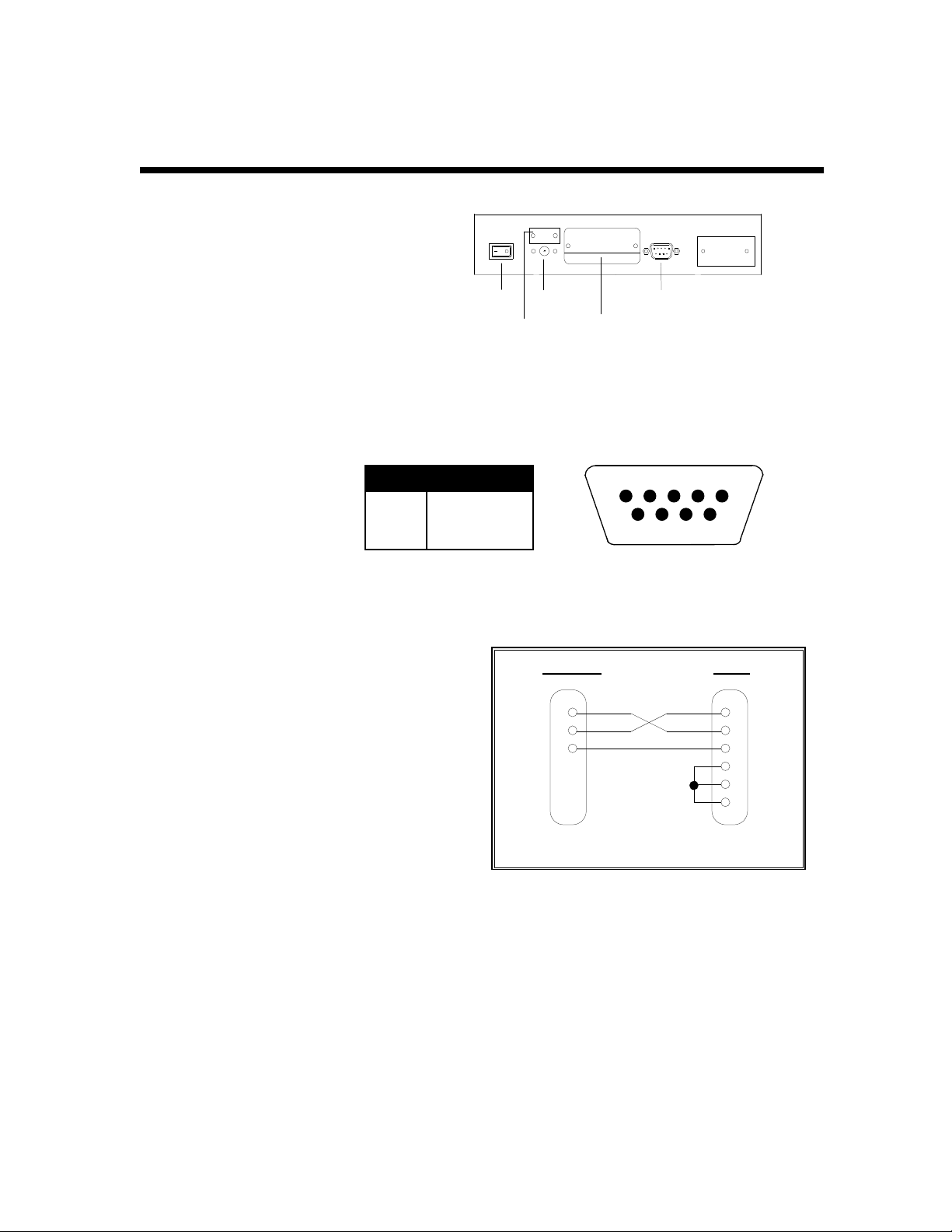
Installation and Wiring
The PC-150 back panel comes equipped
with a female DSUB-9 connector for the
RS-232 serial port, a jack for DC power
input, a calibration switch and an
ON/OFF rocker switch. To install the
scale, simply plug the enclosed AC Wall
Adapter into the scale’s DC power jack
first, then into an AC outlet (115 VAC
only). Finally, turn the rocker switch to the
ON (“1”) position. The scale is now ready
for use.
ON/OFF
SWITCH
DC POWER
JACK
CALIBRATION
SWITCH COVER
RS-232
PORT
ID TAG
PC-150 Back Panel
The female 9-Pin RS-232
connector is used to interface
to a PC. Shown at right are
the pin assignments for the
connector.
Pin No. Pin Name
2
Receive Data
3
Transmit Data
5
Signal Ground
Shown at right is the suggested cable diagram
for direct connection to a PC. Or, you can order
the optional pre-wired NMC-1 Null Modem Cable
235
9-pin RS-232 connector (female)
TO SCALE TO PC
2 RXDRXD 2
TXD 3
S. GND 5
DSUB9 DSUB9
3 TXD
5 S. GND
4 DTR
6 DSR
8 CTS
FIGURE 1. Cable Diagram for Scale to IBM PC
PC-150 Operation Manual
3
Page 4
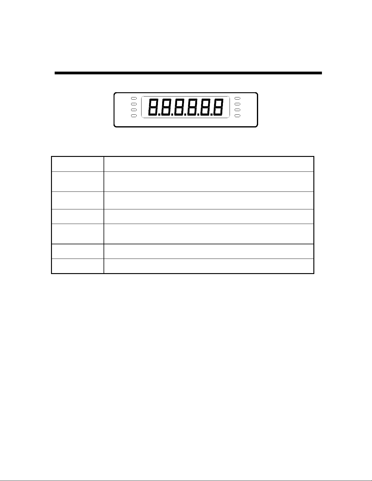
Display Overview
GROSS lb
NET
TARE
ZERO
PC-150 Display Area
ANNUNCIATOR MEANING
kg
STABLE
ZERO
NET
GROSS
TARE
lb and kg
STABLE
Better known as the “Center of Zero” annunciator, this light is active whenever the
displayed weight is within ± 0.25 divisions of true zero.
Indicates that the scale is displaying net weight.
Indicates that the scale is displaying gross weight.
Indicates that the tare weight in the system was established by means of the push
button method.
Indicates the unit of the displayed weight.
This light indicates that the scale is in equilibrium.
4
Revision 1.2
Page 5

Keyboard Functions
lb
ZERO
kg
NET
GROSS
TARE
PC-150 Keyboard
KEY FUNCTION
ZERO
NET
GROSS
TARE
lb
kg
PRINT
Sets scale to display "0" only when a) in Gross mode, b) not in overload and c) not in
motion.
Toggles between Gross and Net weight display if a tare has been established.
Used to establish the weight on the platform as the tare weight. You cannot establish
zero or negative gross weight as a tare. Also, the scale must not be in motion or in
overload.
Toggles between lb and kg units if enabled in the User (“A”) Menu.
Sends "Print" data to serial port if scale is not in motion or in overload.
PRINT
PC-150 Operation Manual
5
Page 6

User Menu Mode
The PC-150 scale includes a User menu that contains the scale's serial communication parameters. It consists of 5 separate menu selections, each also with its own sub-menu of choices.
To change a listed parameter, you must first enter the User Menu mode. Once there, four of the
front panel keys become directional navigators to move around in the menus, and one key is used
to save or SET the selections.
To place the unit in User menu mode:
1. Turn the power off to the unit.
2. While holding down the lb/kg
key, turn the power back on.
3. When the display shows "A1",
the unit is in User Menu mode,
and you can release the lb/kg
key. Shown at right are the directional and SET key assignments
USER MENU CHART
SET
A1
Baud Rate
1200 2400 4800 9600
A2
Data Bits, Parity
8n 7O 7E
19200
A3
Transmission Mode
7n
C d
A4
Serial Data Format
0 1 2 3 4
5
6
A5
Enable lb/kg Key
0 1
To place the unit back into the Normal Operating mode:
1. Turn off the scale. Turn the scale back on without pressing any keys.
2. The display will go through a digit check, then settle into Normal Operating mode. All front panel
keys will now return to their normal mode of operation.
6
Revision 1.2
Page 7

User Menu Mode /
√√√√
Continued
USER MENU DESCRIPTIONS
NAME/CODE DESCRIPTION CODE/VALUE
A1
Baud Rate
A2
Data Bits and
Parity
A3
Mode of Serial
Transmission
A4
Serial Data
Format
A5
Disable the
lb/kg Key
Selects the baud rate for data transmission through the serial port.
Selects the number of data bits and parity of serial transmission.
"8n" = 8 data bits with no parity bit and one stop bit
"7O" = 7 data bits with odd parity bit and one stop bit
"7E" = 7 data bits with even parity bit and one stop bit
"7n" = 7 data bits with no parity bit and two stop bits
Selects when data will be sent out of the serial port to a printer or
computer:
"C" = Continuous mode; send data continuously
"d" = Demand mode; send data when a PRINT command is issued
from the printer, computer, or scale.
Selects the data format to be transmitted via the serial port to a
printer or computer.
"0" = Consolidated Controls Format
"1" = Toledo 8213 Format "2" = NCI 3825Format
"3" = Transcell Technology Format
“4” = Detecto ASD Format “5” = Triner Format
"6" = Fairbanks 70-2453-4 Format
Allows the lb/kg key to be disabled so that an operator cannot accidentally press the key and change the displayed units.
"0" = Disable the lb/kg key "1" = Enable the lb/kg key
1200 2400√√√√
4800 9600
19200
8n√√√√
7O
7E
7n
C
d√√√√
0
1
2
3
4
5
6
0
1√√√√
Setup Menu Mode
The PC-150 scale includes a Setup menu that determines the scale’s display mode, allows scale
calibration and also contains the scale's adjustable functional parameters. It consists of 5 separate menu selections, each also with its own sub-menu of choices.
To change a listed parameter, you must first enter the Setup Menu mode. Once there, four of the
front panel keys become directional navigators to move around in the menus, and one key is used
to save or SET the selections.
PC-150 Operation Manual
7
Page 8

Setup Menu Mode /
Continued
To place the unit in Setup menu mode:
1. Turn the power off to the unit.
2. Locate the calibration switch on
the scale’s back panel and toggle
to the opposite position.
3. While holding down both the
ZERO and PRINT keys, turn the
power back on.
4. When the display shows "F1",
the unit is in Setup Menu mode,
and you can release the two
keys. Shown at right are the directional and SET key assignments
SETUP MENU CHART
SET
F1
Display Mode
0 1
F6
Zero Range
100% 1.9%
F9
Calib. Unit.
0 1
F11
Display Check
Press ZERO
key to begin
F12
Calibration
Press ZERO
key to begin
To place the unit back into the Normal Operating mode:
1. With the scale on or off, toggle the Calibration Switch back to its original position. Turn the scale
back on without pressing any keys.
2. The display will go through a digit check, then settle into Normal Operating mode. All front panel
keys will now return to their normal mode of operation.
8
Revision 1.2
Page 9

Setup Menu Mode /
Continued
SETUP MENU DESCRIPTIONS
NAME/CODE DESCRIPTION CODE/VALUE
F1
Display Mode
Selects display mode for the scale.
"0" = Non-NTEP mode
0√√√√
1
"1" = NTEP mode
F6
Zero Range
F9
Calib. Unit
Selects the range within which the scale may be zeroed. Note that
the scale must be in standstill to zero the scale.
Selects the primary base unit to be used in the calibration process.
Also the default unit for normal operation.
100%√√√√
1.9%
0√√√√
1
"0" = primary unit is lb. "1" = primary unit is in kg.
F11
Display Check
Actuates the function that illuminates all digit segments, decimal
points, and LCD annunciators in a test sequence. Pressing the
Press ZERO key
to begin sequence
ZERO key to scroll down one level begins the test sequence.
F12
Calibration
F13
Factory Reset
Places scale into the calibration routine. Scrolling down with the
ZERO key one level begins the procedure.
This sub-menu will reset all parameters in the “F” and “A” menus to
the default settings. USE WITH CAUTION!!!!!
Press ZERO key
to begin sequence
Press the ZERO
key twice to execute.
NOTE: S
ub-menu F13 restores all parameters in the User (“A”) Menu and Setup (“F”) Menu
to the factory default settings. PLEASE USE CAREFULLY AS YOU MAY LOOSE VITAL
SETUP PARAMETERS!!!
Calibration
CALIBRATION MODE KEY FUNCTIONS
ON/OFF
SWITCH
DC POWER
JACK
CALIBRATION
SWITCH COVER
ID TAG
RS-232
PORT
lb
ZERO
kg
NET
GROSS
SET
TARE PRINT
The scale can be calibrated by following the procedure below. The minimum test weight that can
be used is 1.5 lb (0.7 kg), but 100 lb (50 kg) is the recommended test weight.
PC-150 Operation Manual
9
Page 10

Calibration /
To calibrate the scale:
1. If you are already in Setup Menu Mode, scroll to “F 12” and press the ZERO key. Otherwise,
turn the scale off and set the Calibration Switch on the back panel to the opposite position.
Turn the unit back on.
The message "C 0" appears on the display briefly, followed by a value which remains on the
screen. Allow a 20 minute warm-up period for the load cell and electronics to become thermally stable.
2. Press ZERO to zero the value, then press the NET/GROSS key to save the zero point value.
3. The display will momentarily prompt "C 1" for the span calibration, followed by "0.00" with one
digit flashing. Place the test weight on the platform.
4. Use the four directional keys to adjust the displayed value to the actual test weight value in
pounds. Increase the flashing digit by pressing the lb/kg key. Decrease the flashing digit by
pressing the ZERO key. The position of the flashing digit may be changed by pressing the
PRINT key or the TARE key.
5. After setting the exact value, press the NET/GROSS key to save the value.
6. If the calibration was successful, the display will show "ECAL" momentarily, then freeze. Exit
the Calibration mode and enter the Normal Operating Mode by positioning the Calibration
Switch back to its original position.
Continued
7. If the calibration was not successful, one of the error messages below will appear. Take the
indicated action to correct the problem, then perform a new calibration.
"Err0" - The calibration test weight or the adjusted keyed-in weight is larger than full scale.
Change the calibration test weight or check the keyed-in weight.
"Err1" - The calibration test weight or the adjusted keyed-in weight is smaller than 1% of full
scale. Change the calibration test weight or check the keyed-in weight.
"Err2" - Check keyed-in weight with the actual weight placed on platform.
To place the unit back into the Normal Operating mode:
1. Toggle the Calibration Switch back to its original position.
2. The display will go through a digit check, then settle into Normal Operating mode. All front
panel keys will now return to their normal mode of operation.
10
Revision 1.2
Page 11

APPENDIX A: Specifications
MODEL Non Legal-for-trade Capacity Legal-for-trade Capacity
PC-150 0 - 5 x 0.01 lb (0 - 2 x 0.005 kg)
5 - 70 x 0.02 lb (2 - 30 x 0.01 kg)
70 - 150 x 0.05 lb (30 - 70 x 0.02 kg)
CONSTRUCTION:
Base: Steel and ABS
Platform: ABS
Feet: Non-skid Hard Rubber
DISPLAY:
6 Digit, 0.6", 7-Segment Green LED
OVER CAPACITY ANNUNCIATION:
102% of Full Scale Capacity
OPERATING TEMPERATURE RANGE:
32°F to 104°F
(0°C to 40°C)
APPROVALS
Meets H-44 Class III
at 3,500 divisions
0 - 150 x 0.05 lb (0 - 70 x 0.02 kg)
PLATTER SIZE:
13” x 13” (330 mm x 330 mm)
POWER SOURCE:
AC Adapter, 12VDC, 500mA,
included
WEIGHT:
Net Weight: 24.3 lb (11 kg)
Shipping Weight: 27.8 lb (12.6 kg)
General Class III at
3,500 divisions
COC: 96-136A1
PHYSICAL DIMENSIONS
13.0 in [330.2 mm]
ID TAG
RS-232
PORT
ON/OFF
SWITCH
JACK
CALIBRATION
SWITCH COVER
DC POWER
NOA: AM-5262
13.0 in [330.2 mm]
4.4 in [112 mm]
PC-150 Operation Manual
11
Page 12

APPENDIX B: Troubleshooting the Serial Port
The scale’s serial port operation can be verified by following the procedure below. This procedure
makes use of HyperTerminal - a serial port communication program bundled with Windows 95
and Windows 98 operating systems. A HyperTerminal configuration file is available on the Transcell website.
A comprehensive summary of the various Serial Data Formats (SDF’s) can be found in the PC150 Service Manual.
To test the scale’s serial port for proper operation:
1. Connect the NMC-1 Null Modem Cable or equivalent between the scale and your PC. Make
sure to note which communication port (i.e. COM1, COM2) you are using on the PC.
2. On the scale, select the desired setting in the User Menu, including baud rate (A1), Data Bits
and Parity (A2), mode (A3), and serial data format (A4). Note that all Transcell scales have a
fixed parameter of one (1) stop bit.
3. On your PC, run HyperTerminal. Select the proper settings for the following using the scale’s
settings:
Baud Rate
Data Bits
Parity
Stop Bits = 1
4. Enable the CAPS LOCK key on your PC.
5. This test verifies that the scale is transmitting properly. If the scale is set to Demand mode,
pressing the PRINT key on the scale should echo the weight readout on the PC screen. If the
Continuous mode has been selected on the scale, the PC screen will overrun with weight information.
NOTE: The TOLEDO, NCI, FAIRBANKS and TRINER formats do not support a Continuous
mode.
6. This test verifies that the scale is receiving properly. Use the table below to determine the
valid commands for your serial data format setting. For example the ‘P’ command is executed by pressing the capital “P” key on your PC keyboard. Unless otherwise specified, you
do not need to press the ENTER key on your PC.
NOTE1: If the scale is set to Continuous mode, the print commands will be ignored.
NOTE2: If the scale is in motion, the print commands will be ignored for most SDF’s.
FUNCTION FORMAT(S) COMMAND
Print the weight CONSOLIDATED & TRANSCELL ‘P’
TOLEDO ‘W’
NCI & TRINER ‘W’ + <ENTER>
DETECTO ‘~’
12
Revision 1.2
FAIRBANKS <ENTER>
Page 13

APPENDIX C: Displayed Error Codes
CODE MODE MEANING / POSSIBLE SOLUTION
_ _ _ _ _ _
– HI –
– LO –
Err 0
Err 1
Normal Operating Mode A weight greater than 102% of the scale’s capacity has
been applied to the scale. Remove the weight from the
platter. Try re-calibrating the scale if this doesn’t solve the
problem. Otherwise, possible load cell damage due to
overloading.
Normal Operating Mode Underrange condition. Platter has been removed. Re-install
platter. Try re-calibrating the scale if this doesn’t solve the
problem. Otherwise, possible load cell damage due to
shock loading.
Warmup Mode The scale has been turned on with a weight already present
on the platter. Remove the weight and then press the ZERO
key if necessary. Try re-calibrating the scale if this doesn’t
solve the problem. Otherwise, possible load cell damage
due to overloading.
Warmup Mode The scale has been turned on without the platter installed.
Install the platter and then press the ZERO key if necessary. Try re-calibrating the scale if this doesn’t solve the
problem. Otherwise, possible load cell damage due to
shock loading.
Calibration Mode Keyed-in weight value in Calibration Mode is less than 1.5
lb (0.7 kg). Use a larger test weight or re-adjust value.
Calibration Mode Keyed-in weight value in Calibration Mode is larger than
150 lb (70 kg). Use a smaller test weight or re-adjust value.
Err 2
Err 3
Err 4
Calibration Mode Internal resolution is not high enough to process keyed-in
weight value in Calibration Mode. Verify test weight and
value.
All Modes Diagnostics check error - EEPROM Read
All Modes Diagnostics check error - EEPROM Write
PC-150 Operation Manual
13
 Loading...