

Page 1
SAGEM
MF 3760 - MF 3780
User Manual
S
Page 2

WELCOME
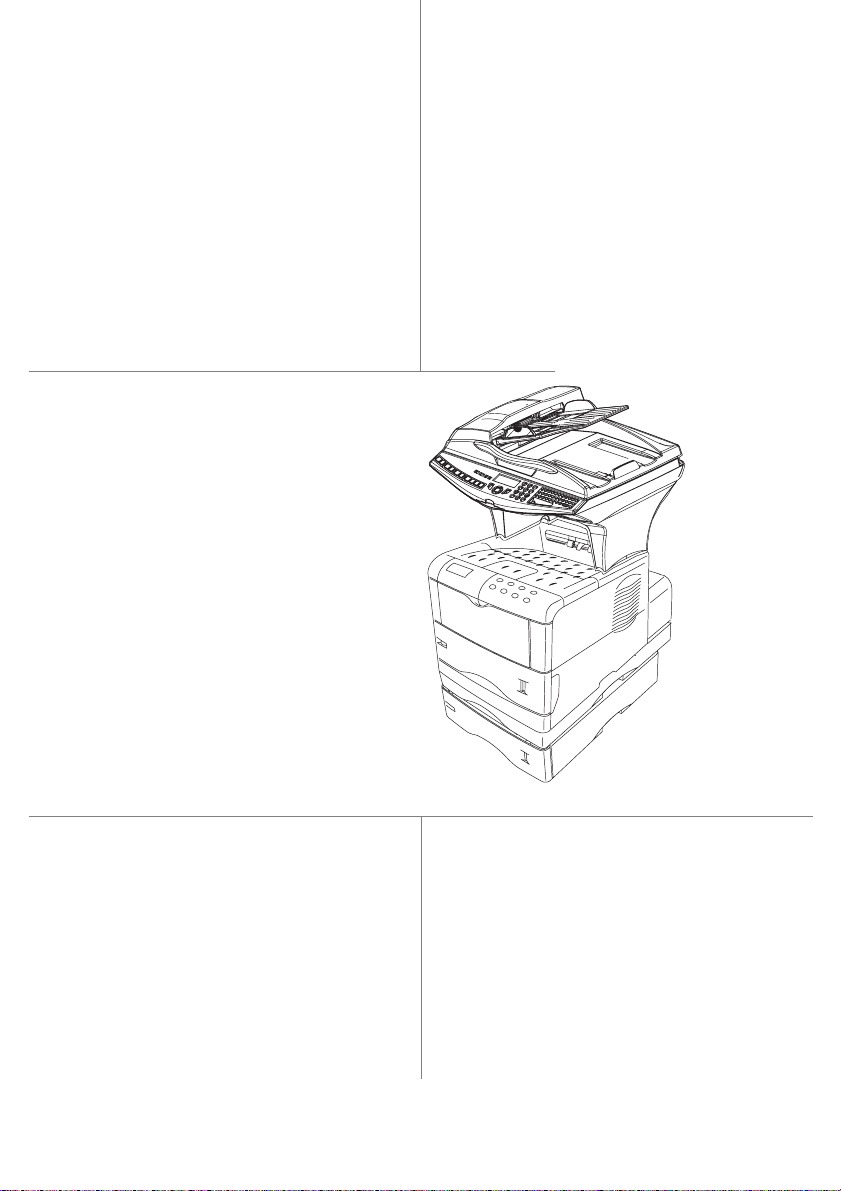
You have just acquired a new generation communications terminal from SAGEM and we congratulate
you on your choice.This mul ti -function terminal is capabl e of faxing, printing and scannin g and
furthermore, can be used for Inte rne t c om munications. Your terminal wi ll me et al l you r professional
requirements.
This User's Manual presents the model in the range:
Model Equipement
• Duplex unit scanner colour
• 33.6 kbps fax and 56 kbps data modem
MF 3760
MF 3780
It combines power, user-friendliness and simplicity thanks to its navigator, its multitask access and its
direct access dir ectory.
Providing access to the Internet, your t erm i na l let s yo u, dep end ing on model:
• send and receive faxes to E-m a il s thanks to the F@x to E-mail function,
• send and receive E- ma ils,
• send SMS's.
Denpending on model, you c an a lso pr in t to PCL® 6 and KPDL/SGScript 3 form ats (emulation of
Postscript® level 3 language).
We strongly recommend that you take the time to read this manual so that you can get the most out of
your terminal's many features. Please read the safety instructions carefully (see the Safety chapter on
page 8-1).
List of accessories
The following additiona l acc essories are proposed for the Fax La ser Pro range:
• Directory card.
• 500-page paper tray.
• Front / rear module (optional depending on model
• Compani on Suite Pro kit PC (depending on model) .
Consumables
To refer to the last page of this user manual for the references.
1
• 28 ppm Black & White laser prin ter
• Emission / reception of SMS
• Front/back modu le
• Companion Suite Pro kit PC
• Bilinear ( d epending on model)
• Duplex unit scanner colour
• 33.6 kbps fax and 56 kbps data modem
• 28 ppm Black & White laser prin ter
duplex-unit
• Emission / reception of SMS
• Front/back modu le
• LAN 10/100 Base T
• Companion Suite Pro kit PC
1. The list of accessories is subject to change without prior notice.
Page 3
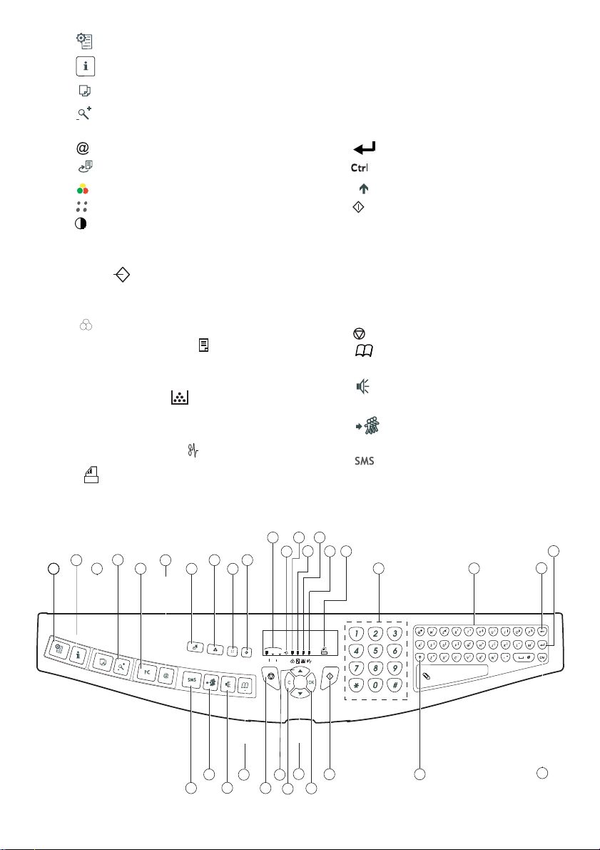
Scanner console
Fine
Sfine
Photo
1. Key :
2. Key :
3. Key :
4. Key :
5. Key PC :
6. Key :
7. Key :
8. Key :
9. Key :
10. Key :
Scan resolution (Fine (Fin), SFine (Super Fin),
11.
Photo)
12. Icon "Ligne" :
* On : communication in progress.
* Falshing : communication set ting up.
13. Icon :
14.
Recto/Verso print indicated
* On : duplex mode activated.
* Out : printing mode deactivated.
15. Indicator reserve "Toner" :
On : end of toner
Flashing : near the end of toner
16.
Indicator printer paper jam
17. Icon
* On : reception possible.
stops current printing.
help in terminal use.
local photocopy.
reduce or enlarge.
scan to PC / scan to FTP.
scan to e-mail (sending of Internet fax).
double sided printing
selection of colour mode
scan resolution
contrast setting
.
.
.
color mode selected
,
.
.
:
.
.
fax reception icon reception
* Flashing : non-printed document(s) in memory
or being received.
* Out : reception impossible.
18.
Digital keyboard.
19.
Alphabetical keyboard
20. Key
Í
:
deletes the character to the left of the
.
cursor
21. Key :
22. Key :
23. Key
24. Key :
25. Key
26. Key :
downwards
27. Key
input or line feed
access to special characters
:
Shift.
send fax
.
OK
:
validates displayed selection
access to menu and browsing in menus
.
.
.
.
C
:
return to previous menu and correction of
text
28. Key :
29. Key :
30. Key :
31. Key :
32. Key : d
browsing in menus upwards
stops current operation
access to directory and quick dial
.
numbers
line manual connection, listen for tone
during fax sending
multiple contact sending (fax, e-mail
.
.
.
or SMS).
33. Key :
:
Service)
sending of an
.
SMS
(Short Message
1
PRINT
11
13
15
14
4
2
3
COPY
COPY
5
6
SCAN
COM
33
8
9
7
32
31
12
10
Fine
Sfine
Photo
28
30
29
16
17
18
26
24
25
27
23
19
21
20
22
Page 4
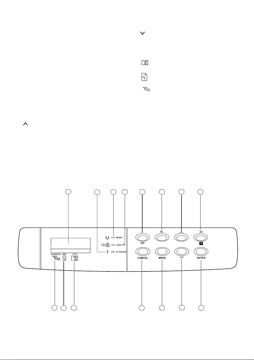
Print console
1. The console's LCD screen.
2.
WARNING
On: A problem or error (e.g. a paper jam) has occurred.
Blinking: The printer requires maintenance or is
warming up.
READY
3.
On: The printer is ready. It prints out any data it receives.
Blinking: An error has occurred.
Off: The printer is idle. The data has been received but
not printed out (see GO key).
DATA
4.
On: The data has been processed or stored on the
memory card,
Blinking: Data transfer in progress.
GO
5.
mode.
6. < key: Used to navigate the submenus and make certain
settings.
7. key: Used to navigate the menus and to increase
numerical values.
8. > key: Used to navigate the submenus, make certain
settings and display help messages when certain errors
indicat o r:
indicator:
indicator:
key: Used to take the printer into or out of idle
occur.
9.
ENTER
key: Confirms the numerical values and other
selections.
10. key: Used to navigate the menus and to increase
numerical values.
MENU
11.
12.
key: Used to access or exit the printer's menu.
CANCEL
key: Used to cancel a print job.
TYPE
13. indicator: Shows the paper type used in the tray.
SIZE
14. indicator: Shows the paper size used in the tray.
INTERFACE
15. indicator: Shows the interface being used (PAR,
USB, OPT and --). taille du papier utilisé dans le bac.
1
15
13
14
3 4
2
5
12
6
11
7
10
8
9
Page 5

Contents
1INSTALLATION 1-1
Installing your terminal 1-1
Installation requirements 1-1
Operational precautions 1-2
Unpacking the components 1-4
Unpacking the additional paper tray
(depending on option)
Unpacking the front/back module
(depending on model or option)
Unpacking the scanner 1-6
Unpacking the printer 1-7
Description 1-8
Installing the terminal 1-9
Installing the additional paper tray 1-9
Installing the front/back module on top of the additional trays (depending on
model or option)
Installing the printer on top of the front/back module 1-11
Installing the feet on the scanner/printer interface 1-12
Installing the scanner on top of the scanner/printer interface 1-13
Fitting the scanner interface to the printer 1-14
Terminal connections 1-15
Installing the cable holders 1-18
Connecting the scanner's mains lead to the printer 1-19
Connecting the printer's LAN and USB leads 1-20
Connecting the scanner's parallel port to the printer 1-21
Taking the various leads out of the terminal 1-22
Fitting the front/back module cover 1-23
Installing the removable components 1-24
Installing the scanner document feeder 1-24
Adjusting the original document
output tray
Loading paper 1-25
Loading the multipurpose tray 1-28
Installation des consommables 1-30
Wall connections 1-33
Telephone and lan connections 1-33
Power line connection and switch on 1-33
Configuring the printer driver 1-33
1-4
1-5
1-9
1-25
Getting startedDirectoryMaintenanceSafety ContentsInstallationPrint function
Setting your
Operation
machine
2GETTING STARTED 2-1
Navigation methods 2-1
Presentation 2-1
The navigator 2-1
Moving within the menus 2-2
The display screen 2-3
Access to functions 2-3
Menu-driven access 2-3
Direct access by number 2-4
I
Page 6

Guide to function list 2-5
PRINT CONSOLE NAVIGATION BASICS 2-9
NAVIGATING THE MENUS 2-9
Control panel keys 2-9
ACCESS TO FUNCTIONS 2-10
Printing out the menu guide 2-10
GUIDE TO FUNCTIONS 2-11
3SETTING YOUR MACHINE 3-1
Main settings 3-1
Before transmission 3-2
Date/Time 3-2
Your fax number/your name 3-2
Type of network 3-2
Geographical settings 3-2
Local prefix 3-3
Transmission report 3-4
Document feed type 3-4
Economy period 3-4
Before reception 3-5
Fax answering machine 3-5
Reception without paper 3-5
Number of copies 3-6
Relay broadcast 3-6
Fax or PC reception (depending on model) 3-7
Duplex printing (depending on model) 3-7
Adjust to page 3-7
Technical parameters 3-8
Local Area Network (LAN) settings (depending on model) 3-11
Local network settings 3-11
Automatic configuration 3-11
Manual configuration 3-11
IEEE address (or Ethernet address) or MAC address 3-12
Netbios names 3-12
Print function settings 3-12
Updating network settings 3-12
Automatically configuring IP settings 3-13
Manually configuring IP settings 3-13
Remote configuration 3-14
System requirements 3-14
Accessing the Web Server 3-14
Message service and the Internet 3-15
Initialisation parameters 3-15
Access to connection and message service parameters 3-16
Access to servers parameters 3-16
Settings 3-18
Standard settings 3-18
Mail sorting 3-19
Internet Connection 3-21
Immediate connection to the Internet 3-21
II
Contents
Page 7

Contents
Programmed connection 3-21
Deactivating the Internet function 3-21
The SMS service 3-22
SMS Parameters 3-22
Sending an SMS 3-23
Erase an SMS 3-24
SMS Reception 3-24
SMS Server 3-25
4DIRECTORY 4-1
Creating subscribers record 4-2
Adding a record 4-2
Creating subscribers lists 4-3
Adding a list 4-4
Adding or deleting a number from the list 4-5
Consulting a record or a list 4-5
Modifying a record or a list 4-5
Deleting a record or a list 4-6
Printing the directory 4-6
Importing a directory 4-6
The file structure 4-6
Procedure 4-8
Exporting a directory 4-8
LDAP server (depending on model) 4-9
Configuration 4-9
Accessing server contacts 4-9
Adding a server contact
to the local directory
4-10
Getting startedDirectoryMaintenanceSafety ContentsInstallationPrint function
Setting your
machine
5OPERATION 5-1
Sending 5-1
Document depositing 5-1
Scanner 5-1
From the flat scanner 5-2
Choosing the resolution/contrast 5-2
Resolution 5-2
Contrast 5-3
Dialling 5-3
From the directory 5-3
Using the last number dialled key 5-4
Transmission over the
Public Switched Telephone Network (PSTN)
Immediate transmission 5-5
Delayed transmission 5-5
Transmission with auto redial 5-6
Transmission over the Internet 5-7
Sending a black and white document to an E-Mail address 5-7
Sending a colour document to an E-mail address 5-7
III
5-5
Operation
Page 8

Sending a typed message to an E-Mail address 5-8
Scan to FTP 5-9
Simply put the file in an FTP server : 5-10
Multi-contact sending. 5-10
Transmission waiting queue 5-11
Immediately perform transmission from the waiting queue 5-11
Consult or modify the waiting queue 5-12
Deleting a transmission on hold 5-12
In the waiting queue select the desired document and confirm your choice with OK.
5-12
Printing a document in waiting or in deposit 5-12
Print the waiting queue 5-12
Cancelling a transmission in progress 5-12
Reception 5-13
Reception over the
Public Switched Telephone Network (PSTN)
5-13
Reception over the Internet 5-13
Copying 5-14
Local copy 5-14
Standard copy 5-14
Duplex photocopies (depending on model) 5-14
"Sophisticated" copy 5-15
Specific copy settings 5-17
Scanner settings 5-17
Other functions 5-19
Logs 5-19
Printing the functions list 5-19
Printing the machine settings 5-19
Counters 5-20
Deposit and polling 5-20
Lock 5-21
Entering the locking code 5-22
Locking the keyboard 5-22
Locking the numbers 5-22
Locking the Internet settings 5-23
Locking the SMS service 5-23
Scan to PC (depends on model) 5-23
Mail box (MBX FAX) 5-24
MBX management 5-24
Creating an MBX 5-24
Modifying the features of a MBX 5-25
Printing the contents of a MBX 5-25
Deleting a MBX 5-25
Printing the MBX list 5-25
MBX deposit in your fax 5-25
MBX deposit in a remote fax 5-26
MBX polling from a remote fax 5-26
Contents
IV
Page 9

Contents
6PRINT FUNCTION 6-1
Using the console 6-1
The console 6-1
Messages displayed 6-1
Interface indicator 6-2
Paper size indicato 6-2
Paper type indicator 6-3
READY, DATA and ATTENTION indicators 6-3
Printing test pages 6-4
Printing out the menu map 6-4
Printing out the current configuration page 6-4
Printing out the detailed configuration page 6-5
Printing out the network interface card configuration 6-5
Printing out the font list 6-5
Paper size and type settings 6-5
Paper size settings 6-5
Paper type settings 6-8
Multi tray mode 6-10
Selecting the paper output tray 6-11
Pagination 6-11
Emulation 6-12
Font 6-13
Character encoding 6-14
Number of Copies 6-14
Page orientation 6-14
KIR 6-15
Draft mode 6-16
Resolution 6-16
Interface 6-16
Parallel interface 6-16
USB Interface mode 6-17
Network interface settings 6-17
CONFIGURING THE PRINTER 6-17
Page protection mode 6-17
Line break 6-17
Carriage return 6-18
80 character mode 6-18
Print density 6-18
Number of pages printed counter 6-18
Language selection 6-18
Automatic page break 6-19
Standby mode 6-19
Reinitialising the printer 6-19
Resource protection 6-19
Setting the alarm 6-20
Auto mode 6-20
Front/back printing error detection 6-21
Getting startedDirectoryMaintenanceSafety ContentsInstallationPrint function
Setting your
Operation
machine
V
Page 10

7MAINTENANCE 7-1
Maintenance 7-1
General 7-1
Replacing the consumables
(toner and drum )
Remplacement des cartouches 7-2
Cleaning 7-10
Cleaning the scanner’s reading devices 7-10
Cleaning the printer 7-10
Servicing 7-11
Scanner calibration 7-11
Incidents 7-11
Communication errors 7-11
Transmission from the feeder 7-11
Transmission from memory 7-12
Communication error codes 7-12
PRINTER INCIDENTS 7-14
Paper jam inside the printer 7-14
Scanner incidents 7-17
Scanner paper jam 7-17
Miscellaneous incidents 7-19
STORAGE 7-19
PACKING AND TRANSPORTING THE UNIT 7-19
Specifications 7-22
7-2
Contents
8SAFETY 8-1
Cet appareil a été conçu conformément aux normes européennes I-CTR37 et CTR21, il est destiné à être racc ordé
au réseau téléphonique com muté (RTPC). En cas de problèm e s , vous de vez contacter dans un premie r lieu votre
fournisseur.
Le marquage CE atteste de la conformité des produits aux exigence s de la directive R&TTE 1999/ 5/C E.
Pour la sécurité des usagers, co nformément à la directive 73/ 23/CE. Pour les perturbations éle ct rom agnétiques
conformément à la directive 89/336/CE.
Le fabricant déclare que les produits sont fabriqués conformément à l’ANNEXE II de la directive R&TTE 1999/5/
CE.
VI
Page 11

Installation
20 cm (40 cm with front/back module)
30 cm
30 cm
1INSTALLATION
INSTALLING YOUR TERMINAL
Getting startedDirectoryMaintenanceSafety ContentsInstallationPrint function
Setting your
machine
INSTALLATION REQUIREMENTS
A proper location helps to ensur e that your printer provides you with the lon g service life for
which it is designed. Double- check to make sure that the loca ti on you select has the following
characteristics.
• Choose a location that is w el l venti lated.
• Make sure you do not obstruct the ventilation grill e s located on the left and right-hand sides
of the unit and at the rear of the Front/Back module. If there is a wall nearby when you install the unit, make sure you install the terminal at the distances shown in the illustration
below in order to make it easier to open t he va rious covers.
20 cm (40 cm with front/back module)
30 cm
1-1
30 cm
Operation
Page 12

Installation
• Make sure there is no chanc e of a mmonia or other organic gasses being gen era ted in the area.
• The grounded power outlet (refer to the safety instructions in the Safety section) you plan to con-
nect to for power should be nea rby and not obstructed.
• Make sure that the printer is not exposed to direct sunlight.
• Avoid areas in the direct airflow of air conditioners, he aters, or ventilator s and areas subject to
temperature and humidity extremes.
• Choose a sturdy, level surface where the printe r wil l not be e xposed to strong vibration.
• Keep the printer away from any objects that migh t blo ck its heat ve nts.
• Do not locate the printer nea r curtains or other combustible obje ct s.
• Choose an area where there is no possibility of the printer being splashed with water or other
liquids.
• Make sure that the surrounding area is clean, dry, and free of dust.
Operational precautions
Note the following important precautions whenever using the printer.
Operating Environment
The following describes the operating environment requir ed w hen using the printer:
•Temperature:
10°C to 35°C (50°F to 95°F) with fluc tu ation of 10°C (18°F) per hour.
• Humidity:
20% to 80% (no condensati on) w i th fl uctuation of 20% per hour.
Terminal
The following describes pre ca ut ion s f or usin g th e te rm inal.
• Never switch the power to the terminal o ff and never ope n th e covers while the unit is printing.
• Never turn the terminal off or open any of its covers during a print operat io n.
• Never place flammable gasses, liquids or objects that generate magnetic forces near the terminal.
• When unplugging the power cord, al ways gras p the plu g and neve r pull on t he cord. A damag ed
cord creates the danger of fire or electrical shock.
• Never touch the power co rd when your hands a re wet. Doing so creat es the danger of elec trical
shock.
• Always unplug the powe r cord before moving the terminal. Failure to do so ca n damage the
power cord, creating the danger of fire or elec trical shock.
• Always unplug the power cord if you do not plan to use the terminal for a long time.
• Never try to remove any secured panel or cover. The terminal contains high-voltage circuit which
creates the danger of elect ric al shock when exposed.
• Make sure that the power to the pri nter is switched off before connecting or disconne cting an
interface lead to the printer (use a shie ld ed interface lead).
• Never try to modify the term i n al . Do in g so creates the danger of fire or elec trical shock.
• Never place any he av y obje cts on the p ower c ord , pull on it or bend i t. Do ing so c reat es the da nger of fire or electrical shock.
• Always make sure the terminal is not placed on the electrical cord or the communications cables
of any other electrical equipm ent. A lso make sure that co rds and ca bles do not get into th e terminal’s mechanism. Any of these conditions cr eate the danger of malfunction and fire.
1-2
Page 13

Installation
• Do not allow water or othe r liquids to spi ll on or near t he termin al. Fire or e lectrica l shock
can occur sho uld water or li q uid come into co ntact with the terminal.
• Should liquid or any piece of metal accidently get inside the printer, immediately turn it off,
unplug the power cord, and contact your dealer. Failure to take this immediate action creates
the danger of fire or electrica l shock.
• Whenever the terminal emits unusually high amoun ts of heat, smoke, an unusual o dor, or
noise, immediately turn it off, unp lug it, and cont act yo ur dea ler. Failure to take this imme diate action creates the danger o f fire or electrical shock.
• Avoid using the terminal during an "electrical storm" as this may involve a risk of electric
shock caused by the lightning.
• Paper for printer: do not use paper previously printed by your terminal or any ot her
printer: the ink or toner deposited on that paper might damage the printing system of
your terminal.
Caution - Be sure to locate the terminal in a well-ventilated location. A minimal amount of
ozone is generated during normal operation of this te rminal. Because of this, an unpleasant odor
may result when t he printer is used for extensive p rinting in a poorly ventilated a rea. For a
comfortable, he althy, and safe oper ation, be sure to loca te the terminal in a well-ventila ted area.
Getting startedDirectoryMaintenanceSafety ContentsInstallationPrint function
Setting your
machine
1-3
Operation
Page 14

UNPACKING THE COMPONENTS
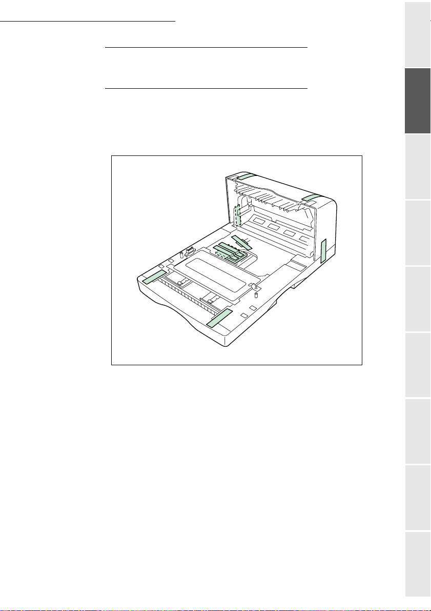
UNPACKING THE ADDITIONAL PAPER TRAY
(DEPENDING ON OPTION)
Take the additional tray out of its box.
Remove the protective side sections in the box.
Remove the plas t ic bag from the addit ional tray.
Installation
To install the additional tray please see the paragraph on Installing the terminal on page 1-9
1-4
Page 15
Installation
UNPACKING THE FRONT/BACK MODULE
(DEPENDING ON MODEL OR OPTION)
Remove the front/back module from its box.
Remove the protective side sections.
Remove the plastic bag from the front/back module.
Getting startedDirectoryMaintenanceSafety ContentsInstallationPrint function
Setting your
machine
To install the front/b ack module, p lease see the p aragraph on Installing the front/back
module on additional trays (depending on model or option) on page 1-9.
1-5
Operation
Page 16
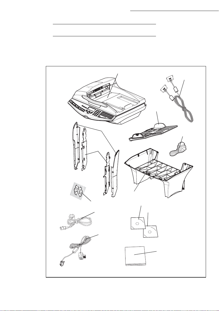
UNPACKING THE SCANNER
Take the scanner module and its accessories out of the box.
Remove the plastic bag from the scanner.
Check that you have al l th e components listed below.
Scanner
Installation
Centronics lead
Document
feeder
Cable holder
Feet
Interface
Cable fasten ers
Mains power cord
(model depending
on country)
Phone cord
(model depending
on country)
Mains extension
lead
Interface
User guide / Printing kit CD-ROM
Companion Suite Pro CD-ROM
(depending on model)
Installation guide
1-6
Page 17
Installation
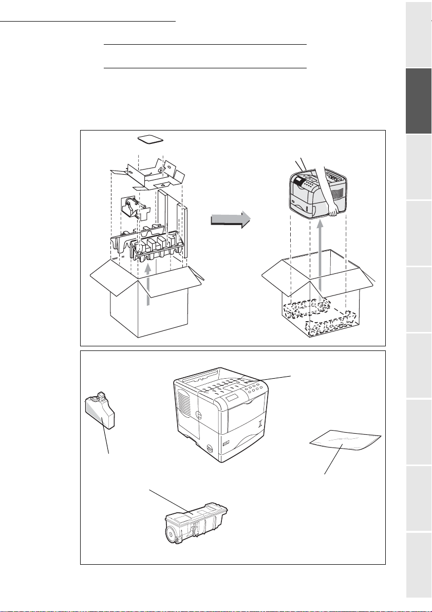
UNPACKING THE PRINTER
Take the printer and its accessories out of the box.
Remove the plastic bag from the printer.
Check that you have all the components illustrated below.
Getting startedDirectoryMaintenanceSafety ContentsInstallationPrint function
Setting your
machine
Waster Toner Box
Toner drum/cartridge
1-7
Printer
A plastic sachet used
to store the developer
(see packing procedure)
Operation
Page 18
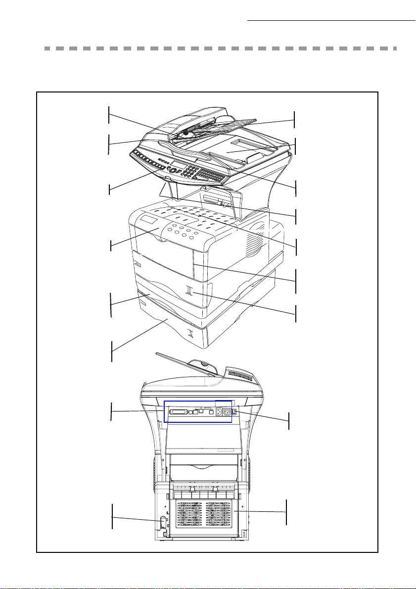
DESCRIPTION
Installation
Adjustable
paper guide
Scroll scanner
(ADF)
Console scanner
Print console
Rear front/back
module cover
(depending on model)
Second paper
tray (optional)
Document feed
tray for scanning
Original document
output stacker
Access handle
Flatbed scanner
Chip card reader
Printer
output stacker
Manual paper
feed tray
Printer paper feed tray
Secteur
connectique
Mains / LAN/ USB/
Line lead outlets
On/Off
button
Mains connection
(depending on model or
optional fa cilities)
1-8
Page 19

Installation
INSTALLING THE TERMINAL
Installing the additional paper tray
You can install up to 3 additiona l paper trays.
Note: stacking paper feeders. (When installing multiple paper feeders).
Getting startedDirectoryMaintenanceSafety ContentsInstallationPrint function
Setting your
machine
Installing the front/back module on top of the additional trays (depending on model or option)
Install the front/back module on top of the additional tr ay (optional).
1-9
Operation
Page 20
Installation
Remove the plug (A) and all the strips of fix ing tape stuck onto the front/back mod ule .
A
Remove the front/back modul e's re ar cover by pressing it inwards (see illustration below ).
1-10
Page 21

Installation
Installing the printer on top of the front/back module
Place the pr in ter on top of the f r o nt/back mod u le and lay it dow n onto this mod u le.
Getting startedDirectoryMaintenanceSafety ContentsInstallationPrint function
Setting your
machine
1-11
Operation
Page 22
Installing the feet on the scanner/printer interface
Position the scanner/pr inter interface unit on top of t he printer, around 3 centime tre s back from
the rear.
Installation
Gauche
2
1
Left interface
foot
Droite
Right inter face
foot
2
1
Insert the scanner/printer interfac e feet i nto the sl ots provi ded for this pur pose, loc ated on both
sides at the rear of the scanner/printer interface, both of the feet have a fool-proofing device and
can only be fitt ed in a single place.
Once both of the feet have been positioned in their respective slots, press upwards until they clip
and then lock into place (see illustration below).
Clipping area
1-12
Page 23

Installation
Installing the scanner on top of the scanner/printer interface
Place the terminal's scanne r on t op of the scanner/printer inter face and then lay it down.
Getting startedDirectoryMaintenanceSafety ContentsInstallationPrint function
Setting your
machine
1-13
Operation
Page 24

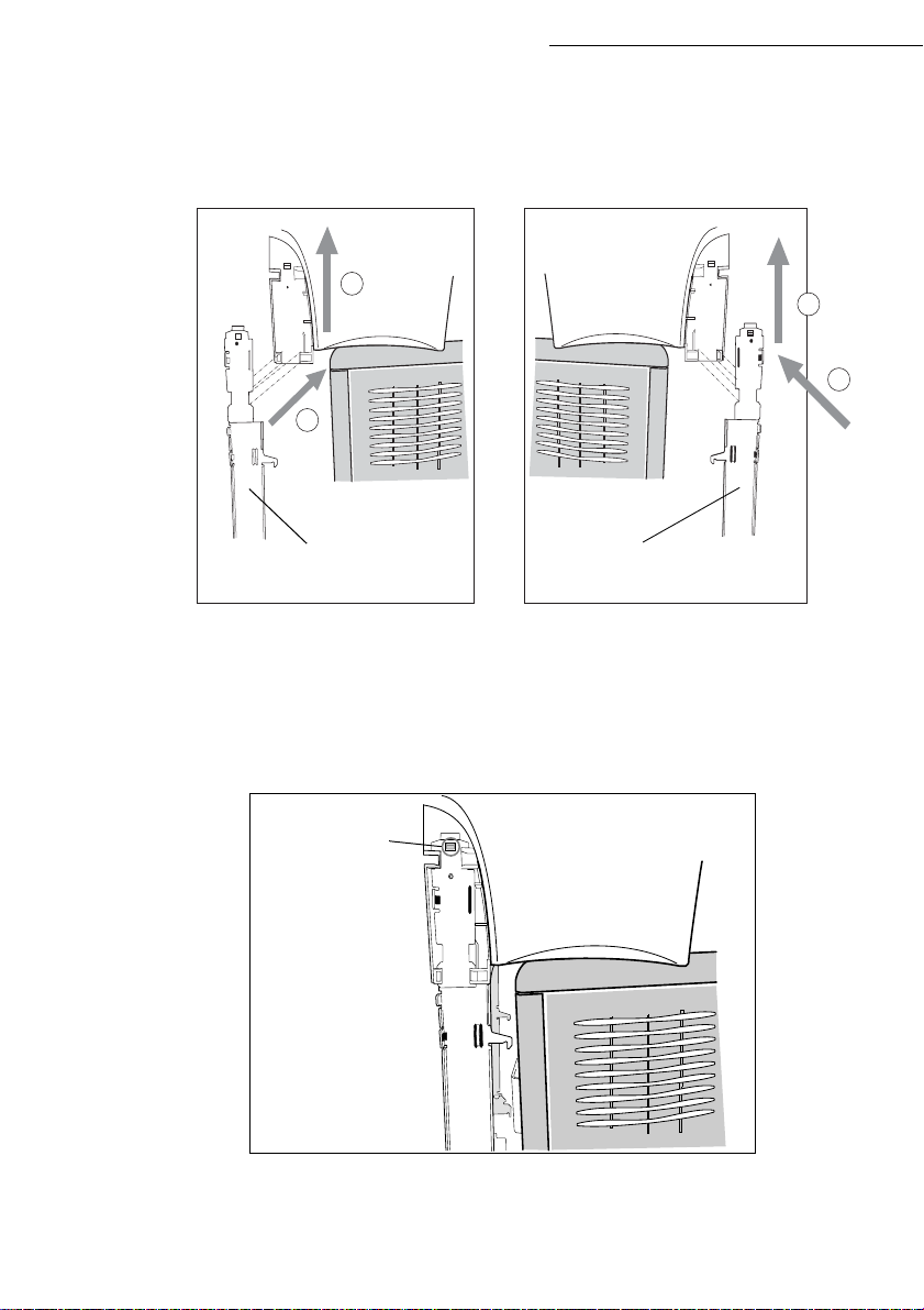
Fitting the scanner interface to the printer
Lift up the scanner/printer interface unit and then position the 4 tabs (B) opposite the 4 slots (A)
located on the left a nd right-hand side at th e rear of the printer. In sert the 4 tabs into the se sl ot s
then press downwards so that the uni t is properly fixed onto the printer.
After fixing the unit onto the printer, make sure that the two blades on the positioning latches (C)
are in a vertical position, if not turn them so that they are in the correct position.
A
C
B
Installation
A
B
C
1-14
A
Page 25

Installation
Terminal connections
If you stand at the rear of the unit you will be able to see all the available connections.
USB
Port
Parrallel
port
Parrallel
port
LAN
socket
L2 telephone
line socket
(depending on
L1 telephone
line socket
Mains socket
Mains extension
On / Off switch
Mains extension
socket
socket
Getting startedDirectoryMaintenanceSafety ContentsInstallationPrint function
Setting your
Operation
machine
USB
Port
LAN
socket
1-15
Page 26

Installation
Connect your terminal's le ads as shown below. D o not forget to lock the Centronics lead into
place using the 2 metal clips.
Locking clips
USB lead LAN lead
(not supplied)
(not supplied)
Centronics
lead
Cordon ligne
téléphonique
Cordon secteur
scanner
Cordon
prolongateur
secteur
1-16
Page 27
Installation
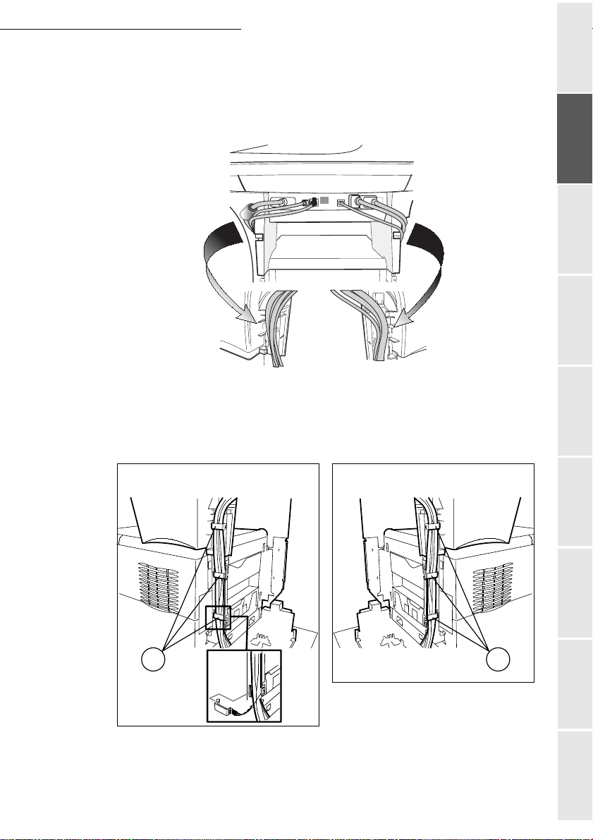
Connecting up the scanner/printer/front/back module
Once the various leads hav e been connected, position them b y inserting them into the
sockets provided for this purpose in the sca nner/ printer in terface 's two side feet as show n
below.
After careful ly pushing the v arious leads into their re spective sock ets, clip the fasteners (A)
onto the scanner/printer interface feet supplied with the scanner (6 fasteners), see
illustrations belo w.
Getting startedDirectoryMaintenanceSafety ContentsInstallationPrint function
Setting your
machine
A
Gauche
Droite
Operation
A
1-17
Page 28
Installing the cable holders
Clip the 2 cable hold ers (see illus trati on below) onto the scanner/ print er inter face f eet to hid e the
leads inside the feet.
Start by fitting the r ight-hand h older. Position the upper p art of the ho lder (A) underneath t he
interface (B). Bring the lower part of the holder (C) against the foot making sure that the middle
clip (D) is in the right position. Clip the whole unit together.
A
Installation
B
A
D
Then fit the left-hand holder in the sam e wa y.
1-18
C
Page 29

Installation
Connecting the scanner's mains lead to the printer
Connect the end of the male/female mains lead (A) to the printer's male connector (E).
Pass the sc anner's mains lead (B) an d the telepho ne lead (F) from underneat h the printer ' s
mains lead (A) see illustrations below.
Make a loop with the mains lead (A) by inserting it into the grommet (D), see illustrations
below.
Getting startedDirectoryMaintenanceSafety ContentsInstallationPrint function
machine
Setting your
A
B
F
E
Operation
D
A
1-19
B
F
Page 30

Connecting the printer's LAN and USB leads
Connect the printer's LAN le ad (C) and USB lead (B) as shown in the illust ra ti on below.
A
B
C
Installation
1-20
Page 31

Installation
A
Connecting the scanner's parallel port to the printer
Connect the end of the lead (A) to the parallel port connector located on the left-hand side
at the back of the printer and lock it into place with the 2 metal tabs.
Pass the USB, LAN and tele phone leads underneath the pa rallel lead (A).
Position the lead (A) on the bottom of the front/back module by runni ng it over the mains
lead and the scanner line lead as sho wn in the illust rat ions below.
Getting startedDirectoryMaintenanceSafety ContentsInstallationPrint function
Setting your
machine
Operation
1-21
Page 32

Taking the various leads out of the terminal
Once you have connected all of the terminal's leads, push them into the slot (A) provided for this
purpose on the left of the front/back module, see illustration below..
A
Installation
1-22
Page 33

Installation
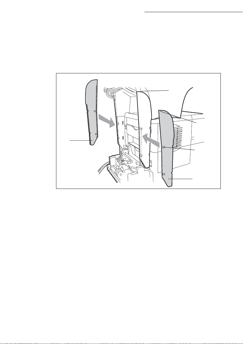
Fitting the front/back module cover
Remove the two flaps (A) from th e rear front/back module cove r.
A
Pass the leads (main s scanner, USB and LAN and line) through the hole (B) which is
provided for this purpose, located on the left-hand side at the rear of the front/back module
cover.
Fix the rear front/back modul e cover into place by clipping to its ba se. Ma ke sure that the
2 clips (C) are properly locked into place.
A
Getting startedDirectoryMaintenanceSafety ContentsInstallationPrint function
machine
Setting your
Operation
B
C
1-23
Page 34

Installation
INSTALLING THE REMOVABLE COMPONENTS
This section tells you how to install the terminal's removable components.
INSTALLING THE SCANNER DOCUMENT FEEDER
Fix the document feeder into place by clicking its two tabs into the appropriate holes (A) on the
terminal.
A
1-24
Page 35

Installation
ADJUSTING THE ORIGINAL DOCUMENT
OUTPUT TRAY
Depending on the format of th e docume nt to be scanne d - A4 or LGAL (LEGAL) ad just
the paper stop.
Getting startedDirectoryMaintenanceSafety ContentsInstallationPrint function
Setting your
machine
LOADING PAPER
Remove the printer paper tra y .
Push the lower tray downwards until it clicks into place.
1-25
Operation
Page 36

Installation
Turn the format dial so that the de sire d format appears in the paper format window.
Note: If the paper format dial is set to OTHER you will need to adjust the paper format on the printer's control panel.
See the user guide.
Paper format
selector
Paper format
indicator
Adjust the paper guides to the paper format by lifting the lever (A) located on the left-hand guide.
A
1-26
Page 37

Installation
Adjust the stop which is located at the rear of the tray by pulling the lev er up w ards.
B5A4
Place the paper into the tray. Be careful to slide the stack under the 2 hooks located at the
bottom of the tray (A).
Getting startedDirectoryMaintenanceSafety ContentsInstallationPrint function
Setting your
machine
A
Caution - Never e xc eed the l oadi n g l im i ts shown on the tray, the tray is designed to hold
500 sheets of 80g/m² paper.
Caution - Neve r add pape r to the tray while the machine is printing.
Kinds of paper which the printer will take:
Printer paper tray 60 to 105 g/m
Manual feeder 60 to 200 g/m
2
2
Close the printer paper tray back up again.
1-27
Operation
Page 38

Installation
LOADING THE MULTIPURPOSE TRAY
If you are printing onto special paper such as 60 to 200 g/m2 maximum co lour pa per or trans parent f ilm
(laser printer-compatibl e), you should use the multipurpose tray which will hold up to 100 sheets of
paper (A4).
Open the multipurpose tr ay cover.
1-28
Page 39

Installation
Put the paper support into place.
Adjust the width between the guide s according to the type of paper you are using.
A4
B5
LTR
A5
Getting startedDirectoryMaintenanceSafety ContentsInstallationPrint function
Setting your
machine
Put the paper in.
Operation
1-29
Page 40

Installation
INSTALLATION DES CONSOMMABLES
Open the printer top cover (A) all the way.
(A)
With the label side down, thorou ghly sha ke th e new ton er cont aine r (D) (in the di recti on of the
arrow) ten times or more to ensure that the toner is evenly distributed inside.
1-30
(B)
Page 41

Installation
Carefully remove the protective seal [orange colored (E)] from the new toner container and
then instal l the container in t o the printer.
(C)
Push firmly on the top of the toner container at the positions marked PUSH HERE until
you hear it click into pla ce .
Getting startedDirectoryMaintenanceSafety ContentsInstallationPrint function
Setting your
machine
1-31
Operation
Page 42

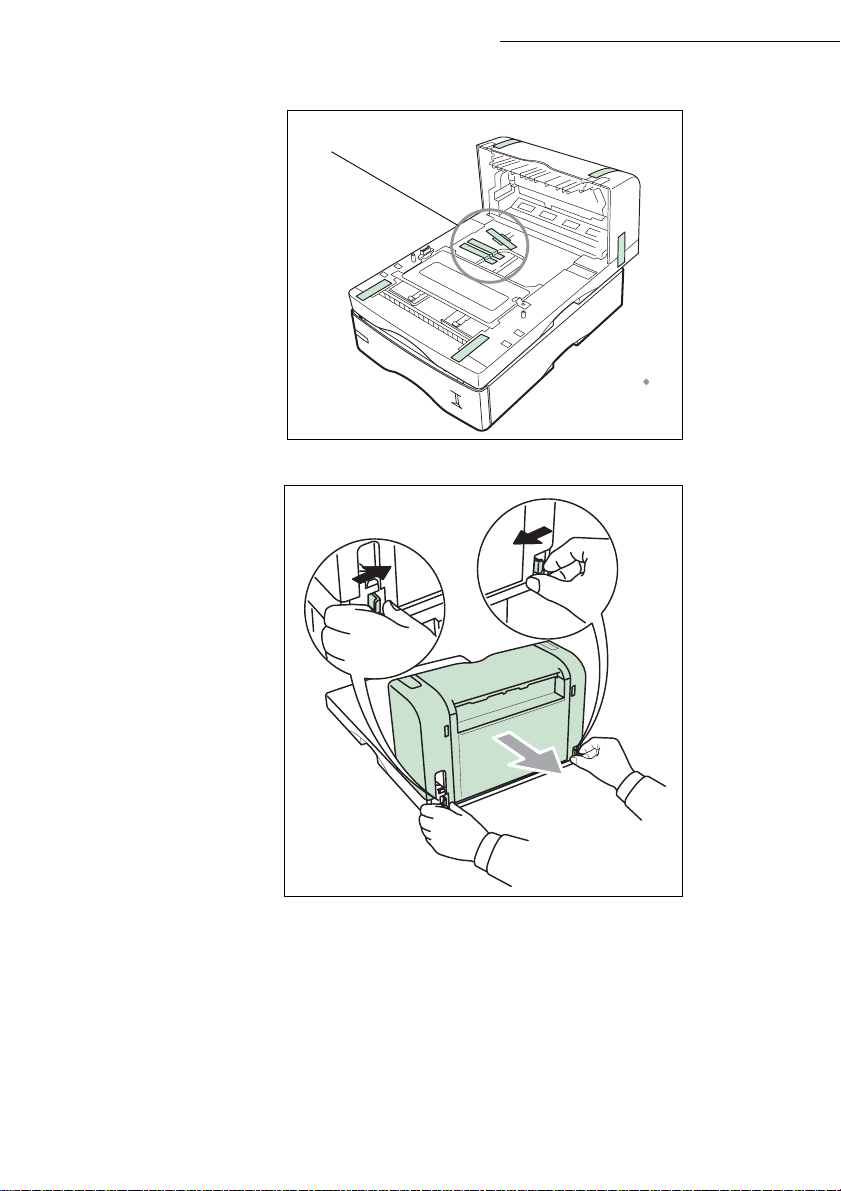
Installation
First open the left cover (D) on the left side of the printer.
(D)
.
Open the cap of the n ew waste toner bo x (K). Insert the ne w waste toner box as shown in the
figure. The box will be locked when it fits into place.
(E)
Close the left cover.
1-32
Page 43

Installation
WALL CONNECTIONS
Caution - Make sure that the On/Off switch is in the 0 (Off) position.
TELEPHONE AND LAN CONNECTIONS
Connect the end of the telephone line lead to the t elephone socket on the wal l (see the
paragraph on Terminal connections, on page 1-15, for instructions on how to connect the
scanner).
Connect the end of the LAN lead (supplie d by your network administrator) into your
terminal's local net work socket (p lease see the paragraph on Terminal connections, on
page 1-15, for instructions on how to c onnect the scanner).
Note: depending on model, the printer and the scanner may have a LAN connection. If you only have one connection,
you will need a hub or a switch.
POWER LINE CONNECTION AND SWITCH ON
Getting startedDirectoryMaintenanceSafety ContentsInstallationPrint function
Setting your
machine
Caution - Refer to safe ty pr oce dures in the chapter on Safety.
Connect the end of th e te rmi na l's sca nner m ain s le ad to th e m ains soc ket on t he wa ll (see
the paragraph on Termi nal c onnec tions, on p age 1-1 5, for i nstruct ions on how to co nnect
the scanner) .
Set the printer's On/Off switch to the "I" (On) position then do the same with the scanner's
switch.
After a few seconds, when the prin ter has warmed up, th e date and time will ap pear. To adju st the
language and time of your terminal, reportez-vous au paragra phe Setting your machine,
page 3-1.
CONFIGURING THE PRINTER DRIVER
If you insta ll t he addi tion al pa per t ray or the fr ont /back m odul e when t he pr inte r dri ver i s alre ady
installed, you will need to co nfigure the printer driver on your PC.
Click on the START button, sel ect CONTROL PANEL and then cli ck on PRIN T ERS.
Right click on the MFK28 icon then choose "Properties".
Click on the peripheral's PROPERTIES tab.
Check the boxes for the options you have insta lled.
1-33
Operation
Page 44

Installation
1-34
Page 45

2GETTING STARTED
NAVIGATION METHODS
PRESENTATION
The navigator gives you acces s to the m enus visible on screen.
The navigator
This navigator has 4 keys and allows you to mov e withi n the menus available on your machine.
2-1
Page 46

Moving within the menus
Getting started
Enter the main menu.
Select the next line in a menu.
Select the previous line in a menu.
Confirm entry and go to the following
menu.
Return to the previous menu.
Confirm and exit from the current menu.
Exit without confirming fro m t he curre nt
menu.
Use key Symbol used
OK
C
Moving within a data entry field
To Use key Symbol used
Move to the right.
Move to the left.
2-2
Page 47

Getting started
To Use key Symbol used
Confirm your entry.
Delete a character by moving the cursor to
the left.
Confirm your entry and return to the initial
screen.
The display screen
The screen has two lines of 16 characte rs.
The cursor shows the line you selected.
1DIRECTORY
2 SETUP
For menus with more than two choices, use the arrows
next (hidden) lines of the me nu (3,4, etc.).
ACCESS TO FUNCTIONS
Access to functions may be achieved in two w a ys.
• Menu-driven access.
• Direct function access.
OK
C
or of the navigator to obtain t he
Getting startedDirectoryMaintenanceSafety ContentsInstallationPrint function
Setting your
Operation
machine
Menu-driven access
You can print the guide to find ou t th e number of a function by pressing the key or by
scrolling through the menus, as indicated below.
Press the key, the functions menu appear.
1DIRECTORY
2SETUP
2-3
Page 48

Use the or navigator arrows to move the curso r in front of the required function.
4 SMS SERVICE
5 PRINT
Validate your choice by pressing OK.
When in the selected menu, use the or navigator arrows to move the cursor in front
of the required sub-function.
51 FUNCTIONS LIST
52 LOGS
Validate your choice by pressing OK.
Caution - The Duplex version cannot be used to print the guide. Therefore it can only be printed on
one side.
Direct access by number
You may print the functions list (M 51 OK) to find out the number of a function.
From the stand-by mode:
Press the M key, enter the number of the required function and validate your choice by
pressing OK.
Getting started
2-4
Page 49

Getting started
GUIDE TO FUNCTION LIST
MAIN MENU 1: DIRECTORY
Fonctions Description de la fonction Page
11 OK - NEW CONTACT Enter a new contact in the directory p. 4-2
12 OK
- NEW LIST Enter a relay broadcas t list p. 4-4
- MODIFY Modify a record or a list p. 4-5
13 OK
- CANCEL Delete a record or a list p. 4-6
14 OK
15 OK
- PRINT Print the directo r y p. 4-6
- SAVE/LOAD Store the directory on a chi p c ard
16 OK
161 OK S
162 OK L
17 OK
18 OK
19 OK
191 OK A
192 OK I
193 OK P
194 OK DN
195 OK P
A.Inaccessible if Menu 91 SUPPLIER i s on WITHOUT ACCESS
AVE Save the directory to a chip card
OAD Load the directory fr om a chip card
- IMPORTATION Enable directory importation by e-mail
- EXPORTATION Export the directory by e-m ai l
- LDAP SERVER Access to a directory server p. 4-9
DRESSE IP address or server name p. 4-9
DENTIFIER Connection identifier p. 4-9
ASSWORD Connection password p. 4-9
BASE Search database p. 4-9
ORT Connection port p. 4-9
A
A
p. 4-8
p. 4-8
Getting startedDirectoryMaintenanceSafety ContentsInstallationPrint function
Setting your
machine
MAIN MENU 2: SETUP
Functions Function description Page
21 OK - DATE/TIME Enter the date and the time p. 3-2
22 OK
23 OK
231 OK S
232 OK M
233 OK E
24 OK
241 OK R
242 OK N
243 OK PC R
244 OK D
245 OK A
25 OK
251 OK T
2511 OK N
252 OK P
2521 OK S
2522 OK P
253 OK L
2531 OK C
2532 OK IP A
2533 OK S
2534 OK G
- NUMBER / NAME Enter your name and your number p. 3-2
- SEND Transmission settings
END REPORT Choose to print the communica ti on report p. 3-4
EMORY SEND. Send from feeder or memory p. 3-4
CO PER. Set the economy period p. 3-4
- RECEPTION Reception settings
EC. PAPER Accept reception without paper p. 3-6
BR OF COPIES Number of copies of rece ive d documents p. 3-6
ECEPT. Choice for PC rec ep ti on p. 3-7
UPLEX Received fax printing in Re ct o /Verso mode p. 3-7
DJUST PAGE Adapt the print scaling p. 3-7
- NETWORKS Setting ne tworks
EL. NETWORK Ajust tel. network settings p. 3-2
ETWORK TYPE Selection of network type
REFIX Activate the dialling prefix p. 3-3
IZE NUMBER Minimum size number to be send w i th pr efi x p. 3-3
REFIX SETTING Setting dialling prefix p. 3-3
OCAL NETWORK LAN pra m et ers settings (depending of model)
ONFIGURATION Sélect co nfi guration mode p. 3-11
DRESSE Fax IP address p. 3-12
UBNET MASK. Subnet mask p. 3-12
ATEWAY Gatewa y #1 a ddress p. 3-12
2-5
Operation
Page 50

Getting started
MAIN MENU 2: S
ETUP
Functions Function description Page
2535 OK IEEE ADRESSE Fax IEEE address p. 3-12
2536 OK N
2537 OK N
29 OK
20 OK
201 OK C
202 OK N
203 OK L
ETBIOS 1 NetBIOS name 1 p. 3-12
ETBIOS 2 NetBIOS name 2 p. 3-12
- TECHNICALS Technicals parame te rs p. 3-8
- GEOGRAPHICAL Geographical settings p. 3-2
OUNTRY Choice of country and langua ge p. 3-2
ETWORK Choice of country
ANGUAGE Choice of language
p. 3-3
p. 3-3
MAIN MENU 3: FAX
Functions Function description Page
31 OK - TRANSMISSION Single- and multiple-address transmission p. 5-5
- ECO TRANS. Send a document during the economy period p. 3-4
32 OK
- POLLING RX Polling request p. 5-20
33 OK
34 OK
- POLLING TX Deposit a document p. 5-20
- MBX SENDING Send to a mailbox p. 5-26
35 OK
- MBX POLLING Poll a mailbox p. 5-26
36 OK
37 OK
- BROADCAST Broadcast transmission p. 3-6
- FAX ANSW. Control of fax answering m achine p. 3-5
38 OK
39 OK
391 OK A
392 OK
393 OK C
- REROUTING Rerouting of received m essages p. 5-6
CTIVATION R er outing activation p. 5-6
DESTINATION Choice your destination p. 5-7
OPY Printing activation of rerouting fax p. 5-7
MAIN MENU 4: SMS S
ERVICE
Functions Function description Page
41 OK - SEND SMS Send SMS p. 3-20
42 OK
431 OK S
432 OK SMS R
433 OK A
441 OK S
442 OK NEW Print new SMS messages
443 OK ALL Print all SMS messages received
451 OK A
452 OK SMS B
453 OK S
454 OK
461 OK SMS C
4611 OK S
4612 OK R
462 OK SMS C
4621 OK R
- READ SMS Read SMS received p. 3-21
- DELETE SMS Delete S M S received
43 OK
44 OK
ELECTION Select SMS to delete
EAD Delete all SMS read p .3-21
LL Delete all the SMS read in memory p. 3-21
- PRINT SMS Printing SMS received p.3-22
ELECTION Select SMS message to print
p. 3-21
p. 3-21
45 OK - PARAMETERS SMS service / SMS parameters p. 3-19
UTO PRINT Automatically print SMS re ceived p. 3-19
EEP Beep on SMS reception mode p. 3-20
ENDER NAME Choose to show/hide sender na me p. 3-20
TERM. ADDR. Terminal address p. 3-20
- SERVER SMS servers settings p. 3-22
46 OK
ENTRE 1 Number of main SM S centre p. 3-22
END NO Transmission number p. 3-22
ECEIVE NO Reception number p. 3-22
ENTRE 2 Number of secondary SMS centre p. 3-22
ECEIVE NO Reception number p. 3-22
2-6
Page 51

Getting started
MAIN MENU 5: PRINT
Functions Function description Page
51 OK - FUNCTIONS LIST Function list printin g p. 5-18
52 OK
53 OK
54 OK
55 OK
56 OK
57 OK
58 OK
- LOGS Print TX and RX logs p. 5-18
- DIRECTORY Print the direc tory p. 4-6
- SETUP User pa ram e te rs pri nting p. 5-19
- COMMANDS Commands list printing (see 65 OK)
- LISTE MBX Mbx list printing (see 75 OK)
- PCL FONTS Internal PCL fonts printing p.5-19
- SGSCRIPT FONTS Internal SG Script fonts printing p. 5-19
MAIN MENU 6: COMMANDS
Functions Function description Page
61 OK - PERFORM Perform a command p. 5-11
62 OK
63 OK
64 OK
65 OK
- MODIFY Update of command p. 5-12
- CANCEL Delete a command p. 5-12
- PRINT Printing of a document in wait queue p. 5- 12
- PRINT LIST Printing of the command list p. 5-12
MAIN MENU 7: MAILBOXES
Functions Function description Page
71 OK - CREATE MBX Creating and modification of a Mailbox p. 5-24
72 OK
73 OK
74 OK
75 OK
- DEPOSIT MBX Storing a document in a Mailbox p.5-25
- PRINT MBX Print conte nt of a Ma il box p. 5-25
- DELETE MBX Delete an empty Mailbox p. 5-25
- PRT MBX LIST Print list of Mailbox p. 5-25
MAIN MENU 8: ADVANCED FCT
Functions Function description Page
80 OK - CALIBRATION Scanner calibration p. 6-17
81 OK
811 OK L
812 OK L
813 OK L
814 OK L
815 OK L
82 OK
821 OK S
822 OK R
823 OK S
824 OK D
825 OK P
826 OK P
84 OK
841 OK R
- LOCK Activate an access limitation lock p. 5-21
OCKING CODE Locking code p. 5-21
OCK KEYBD. Act iva te ke yboard lock p. 5- 21
OCK NUMBER Activate dialling l ock p. 5-22
OCK PARAMETERS Activa te Int ernet settings lock p. 5-22
OCK SMS Activate SMS lock p . 5-22
- COUNTERS See the activity cou n ters p. 5-19
ENT PAGES Printed pages counter p. 5-19
ECEIVED PG Local copie s counter p. 5-19
CANNED PAGE Sent pages counter p. 5-19
UPLEX SCAN Received pages counter p. 5-19
RINTED PG Printed pages counter p. 5-19
RINTED SHT Printed sheets counter p. 5-19
- COPY CIS scanner set ti ng s p. 5-15
ESOLUTION Resolution type choice p. 5-16
2-7
Getting startedDirectoryMaintenanceSafety ContentsInstallationPrint function
Setting your
Operation
machine
Page 52

Getting started
MAIN MENU 8: A
DVANCED FCT
Functions Function description Page
842 OK ZOOMING Zoom setting p. 5-16
843 OK A
844 OK O
845 OK C
846 OK L
847 OK B
85 OK
851 OK P
852 OK P
853 OK P
854 OK S.F
855 OK F
856 OK P
86 OK
SSEMBLED Assembled or not copy choice p. 5-16
RIGIN Origin setting p. 5-16
ONTRAST Contrast setting p. 5-16
UMINOSITY Luminosity setti ng p. 5-17
INDING Binding type choice p. 5-17
- SCAN. & PRINT Réglages imprimante p. 5-17
APER Type of paper choice p. 5 -17
APER TRAY Paper tray choice p. 5-17
APER SAVE Paper sav e activation mode p. 5 -17
MARGINS Set margins p. 5-17
LATBED MARG Sh ee t-feed scanner margins setting p. 5-17
RINTER MARG Printer margins sett ing p.5-18
- CONSUMABLES Consumables status p. 6-1
MAIN MENU 9: INTERNET
Functions Function description Page
91 OK - SUPPLIER Choix du fournisseur d’accès p. 3-13
- INIT. PROVIDER Initialisationof your Provider
92 OK
921 OK C
9211 OK C
9212 OK I
9213 OK P
922 OK M
9221 OK I
9222 OK P
9233 OK E-
923 OK S
ONNECTION ISP parameters p. 3-13
ALL NUMB. ISP call numberl
DENTIFIER ISP iden tifier
ASSWORD ISP pas s w ord
ESS. SERV Message service parameters p. 3-13
DENTIFIER Messa g e s ervice identifier p. 3-13
ASSWORD Message service password p. 3-13
MAIL ADR Message service e-mail address p. 3-13
ERVERS SMTP, POP3 and DNS parameters p. 3-13
9231 OK SMTP SMTP server
9232 OK POP3 POP3 server
9233 OK DNS 1 Primary DNS
9234 OK DNS 2 Primary DNS
924 OK SMTPA
9241 OK A
- IMMED ACCES
93 OK
- SETTINGS
94 OK
UTHENT. SMTP authentification access parameters p. 3-14
CTIVATION SM TP authentification activation
Immediat access to ISP
Internet settins
A
941 OK CONNEC. TYPE Select connection type p. 3-16
942 OK S
943 OK P
944 OK D
945 OK E-
946 OK P
95 OK
96 OK
END TYPE Select transmission type p. 3-16
ERIOD Select the period of connection p. 3-16
EPOSIT NOTI Select to print a deposit notice p. 3-16
MAIL ADDR Choose the address to whic h an e -mail will be sent p. 3-17
RINT Print Internet settings p. 3-17
- E-MAIL
- TRI MAILS
Send an E-Mail
Select the reception typ e
A
A.These menus will appe ar only with val id ISPN setting
A
A
A
p. 3-13
p. 3-18
p. 5-8
p. 3-17
2-8
Page 53

Getting started
PRINT CONSOLE NAVIGATION BASICS
NAVIGATING THE MENUS
Control panel keys
The keys on the console are used to configure the printer. Some keys also have sec ondary
functions.
GO
Note: Any settings made using these keys affect only the current interface.
ENTE
Getting startedDirectoryMaintenanceSafety ContentsInstallationPrint function
machine
?
R
Setting your
Key Function
• Connects and disconnects the printer.
GO
• Prints and then e jects a page.
• Cancels sp ecific errors.
• Cancels a print job.
• Reinitialises the numerical values or cancels a configuration procedure.
• Stops the alarm sound triggered by an error.
• If you press this key during m ode selection: the configurat io n ends and
the printer returns to Ready.
• Selects the emulation, font and character encoding, in order to read a
CompactFlash card, etc.
Used to acces s a section or to en ter numerical values. The > a nd < keys are
used to access or exit a subsection in some of th e control procedures.
Used to acces s a section or to en ter numerical values. The > a nd < keys are
used to access or exit a subsection in some of th e control procedures.
2-9
Operation
Page 54

Getting started
Key Function
Used in the same way as the < key in the mode selection function.
• Used in the same way as the > key in the mode selection function.
• Displays on-line help messages on the screen when there is a paper
jam:
If you press this key when the printer is
tions about the on-line help messages.
If you press this key when the on-li ne hel p is di splayed:
the on-line help is cancelled.
Confirms the numerical values and other selections.
Ready : it disp la ys explana-
ENTE
?
R
ACCESS TO FUNCTIONS
This section explains how to use the menu selection system. The MENU key on t he operator console
allows you to use the menu to configure or adapt the printer environment, making settings such as the
number of copies to be made, the emulation, etc. depending on your own specific needs. You can make
these settings when the printer screen show s Ready.
Note: T he printer applies the most recent settings sent from the application software or from the printer driver, and
these always take priority over any settings made from the operator console.
To navigate vertically within the functions, use the and keys (access the menu shown by
repeatedly pressing one of the keys).
To navigate horizontally within the functions, use the > and < keys. To change or confirm the
configuration of a component, press the ENTER key.
Printing out the menu guide
The list of menus may vary acco rdi ng to w hic h options you have installed.
You can print out the print menu guide by moving within the me nus as shown below.
MENU - - PRINT MENU STRUCTURE
Press ENTER, a blinking "?" appears.
Press ENTER again to start printing.
2-10
Page 55

Getting started
GUIDE TO FUNCTIONS
Functions Description of the function Page
- PRINT MENU STRUCTURE Print out the menu guide p. 2-10
- PRINT CONFIG. PAGE Print out the printer configuration p. 6-4
- INTERFACE p. 6-17
ARALLEL Parallel interface configuration
P
USB USB interface configuration p. 6-17
O
PTIONAL Net w ork interface configurat io n p. 6-17
ETWARE Turn this menu on if you are using the Netware
N
TCP/IP Turn this menu on if you are using the TCP/IP protocol
THERTALK Turn this menu on if you are networking with a
E
P
AGE STATUS OPT When this menu is tu r n ed on, the network
- EMULATION Select emulation type p. 6-12
- FONT p. 6-13
S
ELECT FONT Select font
OUNTRY Select character encod ing
C
ONT LISTS List of available fo nts
F
- PAGE CONFIG
COPIES Set the num be r of copies to be made p. 6-15
RIENTATION Choose the paper orientation p. 6-15
O
L
INE BREAK Action following a line break p. 6-18
ARRIAGE RETURN Action following a carriage return p. 6-18
C
CHARAC. MODE Optimise the number of characters per line p. 6-19
80
- PRINT QUALITY Sets the prin t quality
MODE Image antialiasing mode p. 6- 15
KIR
RAFT MODE Draft mode p. 6- 16
D
R
ESOLUTION Choose resolution type p. 6-17
RINT DENSITY Choose print density p. 6-19
P
- PPTIONAL ROM
- RAM DISK MODE
- MEMORY CARD
- PAPER MANAGEMENT
MULTI TRAY MODE Multipurpose tray operating mode p. 6-10
ULTI TRAY FORMAT Choose the paper forma t in the mu lt ip urpose tray p. 6-7
M
ULTI TRAY MODE Choose the p aper type in the multipurpose tray p. 6-8
M
T
RAY 1 TYPE Choose the paper type in tray 1 p. 6-8
RAY 2 TYPE Choose the paper type in tray 2 (dep ending on opt ion) p. 6-8
T
APER SOURCE Choose the sou rce tray p. 6-11
P
D
UPLEX MODE Switch front /back mode on
TACKER
S
A4/LT PRIORITY Force the printing of letter docum ents in A4 form at p. 6-11
P
APER SETTING
POIDS PAPIER Choose the paper weight p. 6-10
protocol
Macintosh
configuration page is pri nte d out at the same time as
the printer status page.
2-11
rapide
Configuration Prise en mains
RépertoireMaintenanceSécurité SommaireInstallationFonction
Utilisation
impression
Page 56

Getting started
Functions Description of the function Page
CHEMIN DUPLEX
ANNULATION RÉG
- COMPTEURS DE PAGES Number of pages printed counter p.6-19
- AUTRES
LANGUE Choo se the language in which messages wil l be
displayed
S
AUT DE PAGE Set the time before printing out an incomp lete page. p. 6-19
ISE EN VEILLE Set the time before entering standby mode p. 6-20
M
ODE VEILLE Switch the standby mode on p. 6-20
M
I
MPRESSION
INITIALISER Reinitialise the settings to their default values p. 6-20
ESSOURCE PROT. Save downloaded PCL 6 pa ra meters p. 6-20
R
S
ONNERIE Turn the error alarm on or off p. 6-20
ODE AUTO Continue printing after error p. 6-21
M
UTO CONTIN. COMPTEUR Waiting tim e be fore continuing p. 6-21
A
F
IN ERREUR Manage front/back errors p. 6-21
ECTO VERSO
R
SERVICE p. 6-21
I
MPRESSION Print out the status page or log
ÉVELOPPEUR
D
DRUM-CTRL
T
AMBOUR
p. 6-19
2-12
Page 57

3SETTING YOUR
Fine
Sfine
Photo
MACHINE
MAIN SETTINGS
At machine powerup, the screen displays:
FRI 31 DEC 23:59
PLEASE WAIT
Fine
Sfine
Photo
You have to set the date and tim e , tel ephone network, language parameter and verif y the other
parameters listed below .
3-1
Page 58

BEFORE TRANSMISSION
Date/Time
At any moment you may change the date and time on your fax machi ne.
To change the date and time:
Enter the numbers of the requ ired time and date one after an other,
(for example November 8 2004 at 9h33, press 0811040933) and press OK to confirm.
Your fax number/your name
Setting your machine
21 OK - SETUP / DATE/ TIME
Your fax will print out your fax num be r on each document it transmits if you sav e th is num ber and if
the machine is set to
page 3-8).
To save your fax number and your name:
SENDING HEADER (reportez-vous au par agraphe Technical parameters,
Enter your fax number (20 digits m ax.) and press OK to confirm.
Enter your name (20 characters max) then press OK to confirm.
Type of network
You may connect your fax t o either a PSTN or private network such as private automatic branc h
exchange (PABX). You must select the network whi ch is the mo st convenient.
To select the type of network:
Select option PABX or PSTN then confirm your choice with OK.
Geographical settings
These settings will enable you to use your machine in different preset coun tri es using different
languages.
Country
By choosing a country, you ini ti alise :
• the settings for the public t elephone network,
• the language by default .
To select the country:
Select the required optio n and press th e OK key to confirm.
22 OK - SETUP / NUMBER / NAME
251 OK - SETUP / NETWORKS / TEL. NETWORK
201 OK - SETUP / GEOGRAPHICAL / COUNTRY
3-2
Page 59

Setting your machine
Network
This setting enables you to individually set the type of public telephone network so that your
machine can communicate over the public network of the country you have chosen in
compliance with the applicable standards.
Remark : these settings are different from the NETWORK TYPE (p. 2-5), which allo ws you to choose between
public and private network.
To select the network:
202 OK - SETUP / GEOGRAPHICAL / NETWORK
Select the required option and press the OK key to confirm.
Language
This setting enables you to choose a language other than that imposed by the COUNTRY
setting.
To select the language:
203 OK - SETUP / GEOGRAPHICAL / LANGUAGE
Select the required option and press the OK key to confirm.
Local prefix
This function is used when your fax is installed with a private ne twork, behind a company’s
PABX. It allows you to program an additional automatic local prefix (to be defined), enabling
you to automatically exit the c om pany’s telephone network system, but on ly un der certain
conditions:
• the company’s internal numbers, where a pref ix is not req ui red, must be short num bers le ss
than the minimal size (to be defined, for example France has 10 di gi ts),
• the outside numbers requi ring a prefi x, must be lon g numbers gr eater or equa l to the mini-
mal size (to be defined, for example France has 10 digits).
Programming your fax with the loc a l pre fi x consists of two steps:
• defining the minimal size (or equal) of the compa ny ’s outside numbers,
• defining the outgoi ng local prefix of the company’s telephone network. This prefix will
automatically be added as soon as an external number is dialled.
Caution - If you define a local pre fix, do not add it to the n umbers stored in the d irector y, it
will be automatica l ly dialled with each number.
SommaireInstallation
Getting startedDirectoryMaintenanceSafety ContentsInstallationPrint function
Setting your
Operation
machine
Defining the minimal size and the local prefix
252 OK - SETUP / NETWORKS / PREFIX
You can change the default value for the minimal size of the company’s outside number s
and validate with OK. The min imal size will range between 1 and 30.
Enter the outgoing local prefix of the company’s telephone network (maximum
5 characters) and validate with OK.
3-3
Page 60

Transmission report
You may print a transmission report for all communications over the tele phone network (STN).
You may choose between m ore than one criteria for printi ng reports:
WITH: a report is given whe n the transmission was properly performed o r when it is com pletely
•
abandoned (but there is only one report per request),
WITHOUT: no transmission report, however, your fax will note all transmissions that took place in
•
its log (reportez-vous au para gra phe Logs, page 5-18),
ALWAYS: a report is printed with each transmission,
•
ON ERROR: a report is printed only if the transm issio n fai led or is abandoned.
•
With each transmission report from m emory, a reduced version of the first page is au to matically
reproduced.
To select the report type:
231 OK - SETUP / SEND / SEND REPORT
Select the required op tion WITH, WITHOUT, ALWAYS or ON ERROR and confirm yo ur choice
with OK.
Document feed type
You may choose the way you w an t to fee d your documents:
• from memory, transmission will take pla ce on ly aft er mem ory st orage of the do cu ment a nd dia lling. It allows you to get your originals back quickly to free up th e machine.
• from the feeder of the sheet-feed scanner (reportez-vous au paragraphe Document deposi ting,
page 5-1), transmission will occur after di al l ing. It allows transmission of larger documents.
To select the way you want to feed your documents:
232 OK - SETUP / SEND / MEMORY SEND.
Select the op tion MEMORY or FEEDER and va li da te your choice with OK.
Remark : in feeder mode, the reduced image will not appear on the transmission report.
Setting your machine
Economy period
This function allows you to defer a fax transmission to "off-peak hours" and thus reduce the cost of your
communications.The economy period, via the tel ep hone network (at off-peak hours), is preset by
default from 7.00 pm to 7.30 am. Neve rtheless you may change this time slot.
Modifying the economy period:
Enter the hours of the new economy period and confirm your selection with the key OK.
Using the e conomy period:
Enter the call number and confirm with OK.
233 OK - SETUP / SEND / ECO PER.
32 OK - FAX / ECO TRANS.
3-4
Page 61

Setting your machine
BEFORE RECEPTION
Fax answering machine
The Fax answering ma chine allows you to keep confidential document s in storage and to avoid
printing them as you receive them.
The "Fax Messages" indicator light l et s you know the state of your Fax answering ma c hin e:
• Light on: th e answering ma chine is on.
• Blinking: your fax has documents in storage or is in the proc ess of re ceiving faxes.
• Light off : m emo ry full, the termin al cannot receive an y mo re documents.
You can assure document confidentiality by using the 4 digit access code. Once saved, you will
require this access code for:
• printing fax messages in memory,
• activate or deactivate the fax answering machine.
Saving an access code
383 OK - FAX / FAX ANSW. / ANSWER CODE
Enter the cod e (4 digits) and confirm with OK.
Activating or deactivating the answering machine
382 OK - FAX / FAX ANSW. / ACTIVATION
If you saved an access code for your fax answering machine, enter it and validate with OK.
Select the required option WITH or WITHOUT answering machine and confirm you choice
with OK.
SommaireInstallation
Getting startedDirectoryMaintenanceSafety ContentsInstallationPrint function
Setting your
machine
Print fax messages stored in the memory
If you have defined an access code for your fax answering machine, enter it and press OK.
Documents received and stored in the memory are printed.
Reception without paper
Your fax offers you the possibility to either accept or refuse document reception if your printer is
unavailable (no paper...).
If your fax printer is unavailable, you may choose between two modes of reception:
• reception mode
• reception mode
WITHOUT PAPER, your fax saves the incoming messages in the memory,
WITH PAPER, your fax refuses all incoming subscribers.
3-5
Operation
381 OK - FAX / FAX ANSW. / PRINT
Page 62

To select the reception mode:
241 OK - SETUP / RECEPTION / REC. PAPER
Select the op tion WITH PAPER or WITHOUT PAPER and confirm your choice with OK.
Remark : Paper out is indicated by a beep and a message on the screen.
Received faxes are then stored in memory (icon "Fax messages" flashing) to be printed as soon as you add paper
into the feeder.
Number of copies
You may print incoming documents more than once (1 to 99).
To set the number of each document received:
242 OK - SETUP / RECEPTION/ NBR OF COPIES
Enter the wanted number of copi es and confirm withOK.
At each document reception, your fax will print the nu mber of copies requested.
Relay broadcast
Your fax machine (initiator) can relay a document, in oth er words, transmit a document to you r
subscribers via a remote fax and with a precise relay list.
To do this the initiator fax and the remote fax must bo th h ave the relay f u nction.
To relay you need to supply the remote fax with the document and the relay list number. The remote
fax will then transmit th is do cu ment to all subscribers on the list.
Once the relay is activated by your fax and as soon as the document is received by the remote fax, the
document is printed before relaying to all subcribers on the list.
To activate relay from yo ur fax machine:
Insert the document to relay (reportez-vous au paragraphe Document depositing, page 5-1).
Select 37 OK- FAX / BROADCAST.
Enter the remote fax number where you will relay to or choose your dialling mode
(reportez-vous au paragraphe Dialling, page 5- 3) and press OK.
Enter the relay list number us ed by the remote fax and press OK.
You may enter the time you wish to transmit the document next to the current time and press OK.
If you wish to modify the docum e nt feed type, select one of the opti ons FEEDER or MEMORY ,
then press OK.
If you wish, you may enter the number of pages of your documents be fore transmitting.
Setting your machine
Activate relay by pressing key .
The document in the feeder will be relayed either immediately or at a later time (according to your
choice) to the remote fax which will relay the document.
3-6
Page 63

Setting your machine
Fax or PC reception (depending on model)
243 OK - SETUP / RECEPTION / PC RECEPT.
This menu, combined with a software program installed on your PC (supplied or on option
depending on model) will enable you to se lect the machin e you wish to recei ve the document s on:
•fax.
•PC.
• PC if available, fax otherwise.
For more details, please refer to the i nstruction manual provided wi th the softwa re kit .
Duplex printing (depending on model)
This function is only av ai la ble if you have previously inst al le d the duplex module an d the
additional paper tray at the ba ck of your terminal.
After installing the Duplex module at the back of your multi-f unc ti on terminal, you can print
faxes received in two ways:
• SINGLE SIDED
• DOUBLE SIDED
All faxes received ar e printed accordin g t o t he mo de s elected from the menu, no matter how the
duplex key is set.
To select the fax print mode :
244 OK - SETUP / RECEPTION / DUPLEX
Select the required option SINGLE SIDED or DOUBLE SIDED and validate your choice
with the OK key.
SommaireInstallation
Getting startedDirectoryMaintenanceSafety ContentsInstallationPrint function
Setting your
machine
Adjust to page
This option allows you to print out documents automatically adjusting them to the page form at.
To turn adjust to page mode on:
Select the WITH option and confirm your choice using the OK key.
Operation
245 OK - SETTINGS / RECEIVE / ADJUST PAGE
3-7
Page 64

Setting your machine
TECHNICAL PARAMETERS
As delivered your fax is preset by default. However, you may ad just it to m ee t yo ur re quirements by
resetting the technical parameters.
To set the technical parameter s :
29 OK - SETUP / TECHNICALS
Select the desired param e te r and confirm with OK.
With the keys or , modify the parameter se ttings by following the table below and
press OK.
P a r a m e t e r S e t t i n g S i g n i f i c a t i o n
1 - SCANNING
MODE
2 - TX HEADER
3 - TX SPEED
4 - ECHO PROTECT
6 - EPT MODE
7 - COM. DISPLAY
8 - ECO ENERGY
10 - RX HEADER
1 - NORMAL
2 - FINE
3 - SFINE
4 - PHOTO
1 - WITH
2 - WITHOUT
1 - 33600
2 - 14400
3 - 12000
4 - 9600
5 - 7200
6 - 4800
7 - 2400
1 - WITH
2 - WITHOUT
1 - WITH
2 - WITHOUT
1 - SPEED
2 - PAGE NUMBER
1 - WITHOUT
2 - DELAY 5 MIN
3 - DELAY 15MIN
4 - DELAY 30MIN
5 - DELAY 60 MIN
1 - WITH
2 - WITHOUT
Default value of the scan mode resolution for the documents
to be transmitted.
If this parameter is on, your hea d e r w il l a ppe ar on all
documents sent to your subscribers with your name, number,
date and number of pages.
Warning: If you send a fax from the docum ent loader, the
transmission header will not appea r on t he document your
correspondent receives.
Transmission speed for outgoing doc um ents.
For a quality telephone line (compatible, no echo),
communications occur at maximum speed.
However, it may be necessary to restrict the transmission
speed for some calls.
If this parameter is on, the on-line echo will be reduced during
long distance ca lls.
For some long distance calls (satellite), the on-line echo may
disturb the cal l.
Choice between transmission spee d disp la ye d or number of
the page in progress.
Choosing the printer standby delay: the printer will switch to
standby after a delay (in minutes) of NON-operation or during
the period of time of your choi ce.
If this parameter is on, all docum e nts received by your fax
will include the subscriber’s header with his name, number (if
available) fax print dat e and the page number.
3-8
Page 65

Setting your machine
P a r a m e t e r S e t t i n g S i g n i f i c a t i o n
11 - RX SPEED
12 - RINGS
20 - E.C.M.
70 - NET VALID
71 - NET ACTIVE
72 - MODEM SPE ED
73 IMPROVE REP @
1 - 33600
2 - 14400
3 - 9600
4 - 4800
5 - 2400
2 TO 9
1 - WITH
2 - WITHOUT
06:01 TO 21:59
7 DAYS / WEEK
MON TO FRI
1 - 56000
2 - 33600
3 - 14400
4 - 12000
5 - 9600
6 - 7200
7 - 4800
8 - 2400
9 - 1200
0 - 600
1 - WITH
2 - WITHOUT
Transmission speed for incoming documents.
For a quality telephone line (compatible, no echo),
communications occur at maximum speed.
However, it may be necessary to restrict the transmission
speed for some calls.
Number of rings to automatically start your machine.
This parameter helps correct the calls made on
disturbed telephone lines. It is used when the lines are weak
or too noisy. Transmission times may be longer.
This parameter lets you modi fy the period when the fax
connects automatically to the Internet.
This menu is available on ly if the connection type is set to
PERIODIC ( 941).
This parameter lets you select the days of the w eek w h en the
fax connects automat ically to the Internet.
This menu is available on ly if the connection type is set to
PERIODIC ( 941).
Choice of maximum Interne t transmission speed.
For a quality telephone line (compatible, no echo),
communication s occur at the maximum speed.
However, it may be necessary to restrict the transmission
speed for some Internet calls (bad line or bad ISP settings).
This parameter lets you automatically register the Internet
address of your subscribers fax during a call (if available).
SommaireInstallation
Getting startedDirectoryMaintenanceSafety ContentsInstallationPrint function
Setting your
Operation
machine
74 - ERASE
MAILBOX
1 - WITH
When the fax machin e rece ives a n e -mail with an at tach ment
and cannot op en it, it erases the message f rom the ISP MBX,
prints and transmits with a notice of uncomprehension to the
message sender.
3-9
Page 66

P a r a m e t e r S e t t i n g S i g n i f i c a t i o n
Setting your machine
76 - ATTACHMENT
FORMAT
77 - LAN SPEED
80 - TONER SAVE
1 - IMAGE
2 - PDF
AUTO
100 FULL
100 HALF
10 FULL
10 HALF
1 - WITH
2 - WHITHOUT
Default format of document sent on the Internet :
PDF : monochrome or colour
IMAGE : monochrome (TIFF) or colour (JPE G)
To define the communication speed of the peripheral units in
relation to the implemen ted Local Area Network (LAN).
Makes printing lighter to save toner cartridge ink
3-10
Page 67

Setting your machine
LOCAL AREA NETWORK (LAN) SETTINGS (DEPENDING ON MODEL)
Your terminal is a new generation machine that will be part of your local network just like a PC.
Its built-in local network access card will enable you to send documents through an SMTP/POP3
local message server (internally or externally, depending on the settings of your message server).
To benefit from all the avai la bl e network options, you should make the following settings,
described in the sections below:
• local network settings, t o int roduce your fax machine into your local network.
• message service settings, for all your faxes and E-mails to be automatically managed by
your message server.
Caution - Although rathe r simple , network settings som etim es require a sound kn owl edge o f
your own computer configuration. If that is administrated by anyone in your company, we
recommend you ask that person for the settings described below.
LOCAL NETWORK SETTINGS
Automatic configuration
SommaireInstallation
Getting startedDirectoryMaintenanceSafety ContentsInstallationPrint function
Setting your
machine
We recommend that you carry out a manual confi guration of your terminal. T he automatic
configuration of the lo cal network settings may be c onsidered, if your local netw ork features a
DHCP or BOOTP server that can dynamically assign addresses to the peripheral devices present
on the LAN.
To automatically con figure the local n etwork settings:
2531 OK - SETUP / NETWORKS / LOCAL NETWORK / CONFIGURATION
Choose AUTOMATIC and press OK to confirm. The terminal scans the loca l ne twork f or a
DHCP or BOOTP server that can assign it its settings dynamically (the message
SELF-CONF is displayed).
Once the messageSELF-CONF has disappeared, check for the IP Address, Sub-n etwork
mask and Gateway address. If these are missing, you should carry out a manual
configuration (see bel ow ).
Manual configuration
To configure your terminal manually, you should obtain the usual information used to set a
peripheral device (IP addr ess, sub-network mask, network and gate w a y address).
To configure the local network setting manually:
2531 OK - SETUP / NETWORKS / LOCAL NETWORK / CONFIGURATION
Choose MANUAL and press OK to confirm.
Operation
3-11
Page 68

Setting your machine
IP address
2532 OK - SETUP / NETWORKS / LOCAL NETWORK / IP ADRESSE
Enter the IP address of your terminal and press OK to confirm.
Sub-network mask
2533 OK - SETUP / NETWORKS / LOCAL NETWORK / SUBNE T MASK.
Enter the sub-network mask of your terminal and press OK to confirm.
Gateway address
2534 OK - SETUP / NETWORKS / LOCAL NETWORK / GATEWAY
Enter the IP address of the network gateway and press OK to confirm.
IEEE address (or Ethernet address) or MAC address
2535 OK - SETUP / NETWORKS / LOCAL NETWORK / IEEE ADRESSE
The Ethernet card of yo ur terminal already has an unm odifiable, yet consultable , IE E E address.
Netbios names
These names, which can be used with the network options, are used to identify your terminal machine
from a PC connected to a local network (for instance with the name "IMP-NETWORK-1"
2536 OK - SETUP / NETWORKS / L OCAL NETWO R K / NETBIOS 1
2537 OK - SETUP / NETWORKS / L OCAL NETWO R K / NETBIOS 2
Enter the selected name (15 characters max) and press OK to confirm.
PRINT FUNCTION SETTINGS
The printer can be connecte d to the local network as it has its own IP address.
Updating network settings
The print console allows you to:
• turn TCP/IP, NetWare and EtherTalk on or off
• turn DHCP on or off
• enter the IP address, the subnet mask address and the defaul t gateway address.Pour vérifie r ou
modifier
To check or change th e net w ork card settings:
Press the MENU key.
3-12
Page 69

Setting your machine
Repeatedly press the or keys until INTERFACE appears.
One of the interface nam e s bel ow appears, showing that it is th e current interface.
•P
ARALLÈLE (réglage par défaut)
•USB
• Optionnelle (lo rsque la carte réseau est installée)
Press ENTER, a blinking "?" appears.
Repeatedly press the keys or until OPTIONAL appears.
NTER.
Press E
Press the > key
This examp le s ho ws how to s wit c h th e TC P/ IP p ro to col o n to co nn ect t he te rm inal to the
network. You can switch Netwa re or EtherTalk on in the same way.
If TCP/IP is OFF. Press E
NTER again.
Press E
NTER, a blinking "?" appears. Select ON using the or keys.
Automatically configuring IP settings
You can make these settings when the TCP/IP protocol is on. We recommend that you manually
configure your terminal. However, local network settings can be automatically configured if you
have a DHCP or BOOTP server on your loca l ne twork which can dynamically distribut e
addresses to peripherals on the LAN.
To automati cally configu re network local settings:
MENU - - INTERFACE > - - TCP/IP > DHCP
Press ENTER, a blinking "?" appears.
Select ON using the or , then press ENTER.
Press the MENU key.
Switch your terminal off a nd the n back on aga in. Y ou have now finished con figuri ng the
IP address
SommaireInstallation
Getting startedDirectoryMaintenanceSafety ContentsInstallationPrint function
Setting your
Operation
machine
Manually configuring IP settings
You can make these settings when the TCP /I P pr ot oc o l is on .
To configure your terminal manually, you will need th e usua l i nformation for setting up a
peripheral (IP address, subn et mask and gateway address).
To manually configure network local settings:
MENU - - INTERFACE > - - TCP/IP > DHCP
Check that DHCP is se t to OFF. If not press ENTER, then select OFF with the or . keys
NTER.
Press E
Press .
3-13
Page 70

Press ENTER to enter the IP addr ess. A cur sor (_) start s to flash i n the right- hand segm ent (3
figures). Press the key to increment the value and the key to decrement it. Once you have
set the value for the right-hand segment, press the < key to place the cursor in the next segment.
Again, press the key to increment the value and the key to decrement it. Proceed in the
same way for all of the segments. Press E
NTER once all the segmen ts have been set up.
Press .
Enter the subnet mask address in the same way as for the IP address.
Press .
Enter the gateway's IP address in the same way as for the IP address.
Press the MENU key.
Switch your terminal off and then back on aga in. You have now finished configuring the IP
address.
Remarque : Other print-related settings are described in the Print Functions chapter.
REMOTE CONFIGURATION
You can configure the same settings either remotely or locally.
System requirements
Setting your machine
To remotely configure your machine you will nee d:
• a Web browser (preferably Internet Explor er version 4),to make the L ocal Network settings for
your machine (IP address, subnet mask, etc.). You should ask your network administrator for
• these settings. Once you hav e this information, plea se see the paragraph on L ocal Network Settings (depending on model), on page 3-11 on how to fill out the necessary fields.
Accessing the Web Server
Open a Web browser from a PC registered on the network.
Enter the IP address of the term in al you want to configure in t he Address field, as shown in t he
window below:
Confirm by pressing ENTER.
The welcome window is displ aye d, choose the interface language .
Change the settings of your choice on the screen then confi rm.
3-14
Page 71

Setting your machine
MESSAGE SERVICE AND THE INTERNET
Your terminal lets you send and receive documents and E-mails from subscribers throughout the
world over the Internet.
An E-mail is an electronic message sent over the Internet, to an E-mail address (which is a
personal Internet mailbox).
Access to the Internet is possible thanks to an Internet service provider (ISP). The provider puts
at your disposal a server, or computer system which allows you to connect to the Internet and your
mailbox through your telepho ne line.
Before worldwide transmission, you must:
• take out an Internet subscription from an Internet Service Provider (ISP),
• check that all initialisation parameters correspond to those provided by your ISP,
• perform the proper settings, if needed, for the Int ernet connection.
You may then connect yourself to the Internet via your ISP to send and receive fax-Internet or
E-mails. Both operations wi ll be pe rformed during an Internet conn ec ti on.
INITIALISATION PARAMETERS
You must define or, at least check all parameters needed to identify yourself with the Internet.
Your ISP will provide you with these para m et er s as soon as yo u are registered with them.
The parameters are divi ded in three categories:
• connection, allows you to iden tify the dial up number, the conn ection identifier and the
connection password,
• message service, allows you to define the message service identifier, the message service
password and the E-Mail address,
• servers, allows you to identify the nam e of the OP address of Int ernet SMTP providers
(send) and POP3 (MBX reception) and the address of DNS 1 and DNS 2 servers. The server
address is made up of 4 groups of 3 digits maximum, separated by dots.
• SMTP Authentification, used to activate the a uthentification protocol w hen the SMTP se r-
ver used requests this to end e-m ails.
SommaireInstallation
Getting startedDirectoryMaintenanceSafety ContentsInstallationPrint function
Setting your
Operation
machine
3-15
Page 72

Setting your machine
Access to connection and message service parameters
91 OK - INTERNET / SUPPLIER
Select the Internet provider from the list NO ACCESS, PROVIDER_1, PROVIDER_2,
PROVIDER_3, PROVIDER_4, PROVIDER_5, PROVIDER_6 or LOCAL NETWORK, and
press OK.
Choosing
NO ACCESS disables access to Internet func t ion s. OK.
92 OK - INTERNET / INIT. PROVIDER
921 OK - INTERNET / INIT. PROVID ER / CONNECTION
Enter the CALL NUMB., press OK.
Enter connection IDENTIFIER
1
, press OK.
Enter connection PASSWORD, press OK.
922 OK - INTERNET / INIT. PRO V I D ER / MESS. SERV
Enter Email IDENTIFIER, press OK.
Enter Email PASSWORD, press OK.
Enter E-MAIL ADR, press OK.
Access to servers parameters
923 OK - INTERNET / INIT. PROVIDER / SERVERS
Enter SMTP, press OK.
Enter POP3, press OK.
Enter DNS 1 (primary), press OK.
Enter DNS 2 (secondary), press OK.
Access to the authentification SMTP parameters
924 OK - INTERNET / INIT. PROVID ER / SMTPAUTHENT.
In the ACTIVATION menu, select WITH to activate SMTP authentification the n v alidate with OK
key.
In the PARAMETERS menu, select ID.MESS.SERV to keep the same ident if icat ion par amete rs as
in the messaging service or AUTHENT. SPEC. to define other identification parameters, then
validate with Access to SMTP authentification parameters by pressi ng OK ke y. Whe n you select
AUTHENT. SPEC, carry out the two following operations
Enter the IDENTIFIER then validate with OK key.
Enter the PASSWORD then validate with OK key.
1. If the identifier has more than 16 characters, the text will automatically slide over to the left.
3-16
Page 73

Setting your machine
Sample Internet settings for the terminal (56 kbps modem)
Your access provider should give you th e following information:
CALL NUMBER: 08 60 00 10 00
CONNECTION IDENT IFIE R: sg048944@wn.net
CONNECTION PASSWORD: *****
MESSAGE SERVICE IDENTIFER: demo jt12
MESSAGE SERVICE PASSWORD: *****
E-MAIL ADDRESS: demo2@gofornet.com
SERVER:
SMTP mail.gofornet.com
POP mail.gofornet.com
DNS 1 103.195.014.001
DNS 2 103.195.014.002
Non-functional data give n by way of example.
You should then complete the following MENUS on your fax machine:
91 SUPPLIER PROVIDER 1
CONNECTION
9211 CALL NUMB. 0860001000
9212 IDENTIFIER sg048944@wn.net
9213 PASSWORD *****
MESSAGE SERVICE
SommaireInstallation
Getting startedDirectoryMaintenanceSafety ContentsInstallationPrint function
Setting your
Operation
machine
9221 EMAIL ID demo jt 12
9222 EMAIL PASSWORD *****
9223 E-MAIL ADR demo2@gofornet.com
SERVERS
9231 SMTP mail.gofornet.com
9232 POP3 mail.gofornet.com
9233 DNS 1 103.195.014.001
9234 DNS 2 103.195.014.002
3-17
Page 74

9241 ACTIVATION With or Without
Your terminal is now configured.
The settings are divided into several categories:
•the standard settings define the connection type and frequency t o the Internet as well as the
transmission type for your documents,
•the E-mai l sorting defines treatment for all stored E-mail messages received.
Standard settings
Your machine has two types of settings that let you define:
• The type and frequency of the connection to your ISP.
Setting your machine
SMTP AUTHENT.
SETTINGS
SET TIMES
PERIODIC
an Internet connect ion is established every day a t
9:00 a m, 12:30 a m and 5:00 pm
A
an Internet connect ion is established every 3 hours1.
(default value)
an Internet connect io n is established at your request by
ON DEMAND
IMMED. ACCESS (reportez-vous au paragraphe Internet
Connection, page 3-21)
A. To avoid Internet access saturation, the automatic connection will occur in reality 12 minutes,
give or take, around the requested time.
• Type of transmission over the Internet.
IMMEDIATE
DURING
CONNECTIONS
document transmi ssion will occur immediatel y at each
transmission request
transmissions will only occur at programmed connections
SET TIMES or PERIODIC TYPE
At any moment you may print the settings of you r machine to know their status.
Selecting the connection type
941 OK - INTERNET / SETTINGS / CONNEC. TYPE
Select one of the connection options among SET TIMES, PERIODIC or ON DEMAND and
press OK to confirm.
3-18
Page 75

Setting your machine
Selecting the transmission type
942 OK - INTERNET / SETTINGS / SEND TYPE
Select one of the send options IMMEDIATE or DURING CNX then press OK to validate.
Changing the connection period (PERIODIC type)
943 OK - INTERNET / SETTINGS / PERIOD
With the PERIODIC mode, enter the new connection period by means of the numerical
keypad (between 00:01 am and 11:59 pm) and press OK to confirm.
An Internet connectio n w ill be established every three ho urs (default value).
Selecting the print mode for the deposit notice
944 OK - INTERNET / SETTINGS / DEPOSIT NOTI
Select one of the deposit notice opt ions WITH, WITHOUT, ALWAYS or ON ERROR and
press OK to confirm.
Choosing the address to which an e-mail will be sent
945 OK - INTERNET / SETTINGS / RETURN ADDR
Enter the e-mail address then confirm using the OK key.
Printing the Internet settings
946 OK - INTERNET / SETTINGS / PRINT
The Internet settings are printed.
These settings may also be print ed toge th er with all the other settings of your mac h in e
(reportez-vous au paragraphe Printing the machine settings, page 5-1 9).
SommaireInstallation
Getting startedDirectoryMaintenanceSafety ContentsInstallationPrint function
Setting your
machine
Mail sorting
This function lets you choose the mode for all Internet documents stored in your mail box.
You have three choices:
F@X ONLY, lets you poll and print E-Mails in your machine.
•
PC ONLY, lets you keep your E-Mails in you mail box for later use with a computer (no
•
E-Mail poll),
SHARE PC lets you:
•
- if your PC and fax have two di fferent a ddresse s, tran sfer al l mail s or only tho se wi th atta chments to a PC,
- if your PC and fax share the same address, use the fax as a printer for E-Mails for the PC.
F@X Only mode
Select option F@X ONLY and press OK to confirm.
All E-Mails are polled and printed.
Operation
96 OK - INTERNET / TRI MAILS
3-19
Page 76

Setting your machine
PC Only mode
Select option PC ONLY and press OK to confirm.
The E-mails are neither polled nor printed and they ma y be used with a computer.
At each connection, the numbe r of E-mails in your mailbox is displaye d on th e screen.
Share PC mode
Select option SHARE PC and press OK to confirm.
You may choose to transfer your E-mails to a PC or use the fax as an E-mail printer.
To transfer the E-Mails to a PC:
Select option WITH PC TRANS. a nd pre s s OK to confirm.
Enter the E-Mail address of the computer you wish to transfer your E-M ail and press OK to
confirm.
Select your option from the table below and press OK to confirm.
Menu Description
SEND ALL MAILS All E - M ails are sent to the PC.
UNUSABLE ATTAC
To use the fax as an E-Mail print er:
The fax machine po lls and prints the u sable E- mails and tran sfers t o
the PC mailbox all the E-mails containing attachments it cannot use.
Select option W/O PC TRANS and press OK to confirm.
Select your option from the ta bl e below and validate with OK.
Menu Description
DELETE MAILS
SAVE MAILS The E-mails opened and read by the fax are not erase d.
At each connection, the num be r of E -mails still present in your mailbox a re displayed on the screen.
The E-mails ope ned and re ad by the fax (w/o attachment) are erased
after the fax has printed.
3-20
Page 77

Setting your machine
INTERNET CONNECTION
An Internet connection is made with an ISP. It allows both document sending and reception while
connected.
A connection takes place the following way:
• Send to one or mo re of your subscriber ’s Internet mailbox es, all fax-Internet docu ments
waiting for transmission.
If you are sending to a co mp uter, the tr an s mitted fax will be receiv ed as an attachment to an
E-Mail.
• Reception of all fax-Intern et and E-Ma il s deposited in your personal Internet mail box.
You may connect eit her immediately or automatically depending on the time period s defi ne d.
The triggering of a programmed Internet connection depends on the standard settings of your
machine.
Immediate connection to the Internet
There are twomethods to immediately connect to the Internet:
Access through the menu:
93 OK - INTERNET / IMMED ACCES
Direct access:
Press the key twice.
Programmed connection
SommaireInstallation
Getting startedDirectoryMaintenanceSafety ContentsInstallationPrint function
Setting your
machine
An automatic connection to the Internet depends on how your machine is programmed and more
particularly on the standard settings (reportez-vous au paragraphe Standard settings, page 3-18).
DEACTIVATING THE INTERNET FUNCTION
If you do not wish to use the Internet functio ns:
91 OK - INTERNET / SUPPLIER
Select NO ACCESS in the ISP list and confirm with OK.
3-21
Operation
Page 78

Setting your machine
THE SMS SERVICE
Thanks to the e button you can send an SMS to subscribe rs all ove r th e worl d. A n SMS (Short
Message Service) is a service which permits short written messages to be sent to mobile phones or other
SMS-compatible devices.
The number of charact er s you can send per message is depende nt upon the service provider and the
country you are sending your SMS from (e.g. Germany 160 characters, Italy 640 chara cters).
The SMS service is dependent upon t he c ountry and the service provider.
Caution: There is a special scale of charges for the SMS service.
SMS PARAMETERS
This menu is u s ed to set several options:
• automatic SMS print on reception,
• beep activated during SMS recept ion,
• send your details activated,
• the address of your terminal.
The address is only modified i f seve ra l terminals are installed on your line . It is used to differentiate
between two machines during SMS reception.
When you want a contact to send SMSs to the term inal you choose, you must send him your line
number and the destination terminal address.
If your contact does not add the address of the terminal, the SMS will be received in the terminal with
address 0.
45 OK - MAIN MENU 4: SM S SERVICE / - PARAMETERS
Automatic print of SMS received. .
451 OK - MAIN MENU 4: SMS SERVICE / - PARAMETERS / AUTO PRINT
Select the op tion WITH or WITHOUT automatic print, then validate with OK key.
Beep activated on SMS recept io n
452 OK - MAIN MENU 4: SMS SERVICE / - PARAMETER S / SMS BEEP
Select the op tion WITH or WITHOUT BEEP on reception, then validate with OK key.
Presentation of SMS sender
453 OK - MAIN MENU 4: SMS SERVICE / - PARAMETE RS / SENDER NAME
Select the op tion WITH or WITHOUT presentatio n of th e sender, then validate with OK key.
Terminal address
454 OK - MAIN MENU 4: SMS SERVICE / - PARAMETERS / TERM. ADDR.
Enter the terminal number, then validate with OK key.
3-22
Page 79

Setting your machine
SENDING AN SMS
To send an SMS to any SMS-compatible devices:
Press the key
Write your SMS by means of the Qwerty keypad
To do so, you have a true editor at your disposal:
•for the upper case letters, us e the
•to move inside the data entry fi el d, us e the or keys
•to move in the text from one word to another, press the C
keys
•to go to the next line, use the key
•to de l ete a char ac ter (by moving the cursor to the left), use the Í or C key
Pres the key to confirm your entry
Dial the number of the rec ipient (mobile phone or any ot her SMS-compati ble device) in
one of the following ways:
• dial the number by means of the numerical keypad
• enter the first letters of the recipient name
• press the key until the required name appears (names are classified in alphabetic al
order)
• Press the . key to send the SMS.
Your SMS may be sent to only one person or to sever al peo ple. To sen d an SMS:
• to only one person, press the key to confirm
• to several people:
- press the key and enter the next person 's nam e ,
- repeat the operations as many times as requi red (10 persons max.). Press the key to
confirm.
SENDING SMS is displayed as the SMS is being sent.
• If SMS appears, then the SMS has been put on hold and a further attempt will take place a
couple of minutes later. To immediately execute or cancel transmission, reportez-vous au
paragraphe Transmission waiting queue, page 5-11.
• To check the SMS has been sent properly, you may print the transmission/ reception log
52 OK - PRINT /LOGS, p. 2-7).
(
Ï
TRL key and one of the navigato r
SommaireInstallation
Getting startedDirectoryMaintenanceSafety ContentsInstallationPrint function
Setting your
Operation
machine
3-23
Page 80

ERASE AN SMS
Proceed as follows to erase an SMS:
43 OK - MAIN MENU 4: SMS SERVICE / - DELETE SMS
Select the messages to erase.
431 OK - MAIN MENU 4: SMS SERVICE / - DELETE SMS / SELECTION
Select SELECTION using key s and and validate with OK key.
Select a message using keys and and validate with OK key.
Erase messages already read
432 OK - MAIN MENU 4: SMS SERVICE / - DELETE SMS / SMS READ
Select ME SS AGES READ us i ng keys and and validate with OK key.
Confirm with OK key.
Erase all messages from memory.
433 OK - MAIN MENU 4: SMS SERVICE / - DELETE SMS / ALL
Select ALL using keys and and validate with OK key.
Confirm with OK key.
Select ALL using keys and and validate wit h OK key.
Confirm with OK key.
Setting your machine
SMS RECEPTION
SMS messages received are automatically printed (you can modify this setting with 451 OK Auto
print). If you disable automatic printing, the messages are automatically stored in the memory.
SMS read
Access by menus:
42 OK - MAIN MENU 4: SMS SERVICE / - READ SMS
•Direct access
Press key .
Select READ SMS using keys and and valida te with OK key.
Select a message using keys and an d validate with OK key.
Scroll messages using ke y s and .
3-24
Page 81

Setting your machine
Print an SMS
Access by menus:
44 OK - MAIN MENU 4: SMS SERVICE / - PRINT SMS
• Direct access
• Select PRINT SMS using keys
• Select SELECTION (to choose messages to print), NEW (to print all unread messages) or
ALL (to print all messages in memory) using keys
and and validate with OK key.
and and validate with OK key.
Confirm with OK key.
SMS SERVER
This menu is used to set the transmission and reception numbers of your SMS centers. They will
be provided by your access provider. You can define two SMS centres, one main and one
secondary. The secondary cen tre m ay on ly be used for SMS reception.
Access to server mode
46 OK - MAIN MENU 4: SMS SERVICE / - SERVER
Define SMS centre numbers 1
461 OK - MAIN MENU 4: SMS SERVICE / - SERVER / SMS CENTRE 1
Define send number
4611 OK - MAIN MENU 4: SMS SERVICE / - SERVER / SMS CENTRE 1 /
Enter the send number of your mai n SMS ce ntre, then validate with OK key
Define reception number
4612 OK - MAIN MENU 4: SMS SERVICE / - SERVER / SMS CENTRE 1 /
RECEIVE NO
Enter the reception number of your main SMS centre, then validate with OK key.
SEND NO
SommaireInstallation
Getting startedDirectoryMaintenanceSafety ContentsInstallationPrint function
Setting your
Operation
machine
Define SMS 2 Centre numbers
462 OK - MAIN MENU 4: SMS SERVICE / - SERVER / SMS CENTRE 2
Define reception number
4621 OK - MAIN MENU 4: SMS SERVICE / - SERVER / SMS CENTRE 1 /
RECEIVE NO
Enter the reception number of your secondary SMS centre, the n validate with OK key.
3-25
Page 82

Setting your machine
3-26
Page 83

4DIRECTORY
Your fax lets you create a direc to ry by m em orising subscriber records and subscriber lists.
• Your machine can store up to 500 subscriber records with names and phone numbers.
• You may also group several names to bui ld a subscr ibe r list wi th up to 32 subscriber lists.
A subscriber list is made from the subscriber records already stored.
For all subscriber records or subscriber lists you may:
•create
•consult
• modify contents
•delete
• print the directory
You may save and if needed load your directory. To proceed, you need to contact your reseller and
purchase the optional "Dire ctory card". This gives you access to functions 161 and 162
(reportez-vous au paragraphe Guide to function list, page 2-5). To proceed, you need to contact your
reseller and purchase the opt ional kit "save".
4-1
Page 84

Directory
CREATING SUBSCRIBERS RECORD
For each contact record, complete the fields listed below. Only fields with the Name and
Telephone number have to be completed:
•Contact NAME,
• TEL and fax numbe r of contact,
• E-mail addres s, example: dupont@m essagerie.com,
or
• FTP address, exampl e: 134.1.22.9
Remark : If you have not entered an e-mail address, then you have the possibility of entering an FTP address (for archiving
Remark : If a contact has the two fields TEL and E-MAIL completed, the validation key ( or ) will define whether
purposes).
• FORMAT: by default, the attachment is PDF or Image (.tiff or .jpeg)
• RECORD NUMBER: this number is automatically allocated by the fax (you can, none the less,
modify it). It gives you quick access to the directory,
• RATE send fax you can choose for each contact the minimum send rate for fa xes you sen d to him.
Available rates are 2400, 4800, 7200, 9600, 12 000, 14400 and 33600 bi ts per secon d. The m aximum speed can be used if the teleph one line is of good quality, meaning appropriate, without
echo.
the document is sent by telephone network or via the internet.
ADDING A RECORD
Your fax has just created a new record , fill in it by first entering your subscri ber’s name then
validate with OK.
To associate an e-mail address :
Remark : you can stop the list creation at any time by pressing .
Enter the person’s fax numbe r
Enter the E-Mail address of your subscriber and press OK to confirm.
Your subscriber’s ID number will aut omati ca lly appear on the scree n, i f yo u wis h to mod ify th is
number you may do so by ch oosing another free number and validate with OK.
Select the option WITH assigned key if you want to assign a letter (shortcut key) to your
subscriber. Th e first avai labl e letter appear s by def aul t. If you wa nt to change it, sc roll t he lett ers
by menas of the
or keys, and press OK to confirm.
If need be, select the appropriate transmission speed to send your faxes, and confirm your choice
by pressing the OK key.
1. If your machine is connected to a PABX, you may need to insert a pause for dial tone (symbolised by the sign / in the num-
ber) except if a local prefix is already programmed (see § Local Prefix)
1
and press OK to confirm.
4-2
11 OK - DIRECTORY / NEW CONTACT
Page 85

Directory
To associate an FTP address :
Do not enter the e-mail add ress.
Enter the FTP address of the contact, then validate with OK key (for example: 134.1.22.9).
Enter the FTP user na me (for example: Durand).
Enter the PASSWORD of the FTP user.
If necessary, enter the file destination directory (when this field is not completed, the files
are stored directly under the root) o f the FTP server (for exampl e: server name / Durand).
Define the attachment fo rm at (Image or PDF) OK.
A number allocated to your co nt act wi ll be autom ati cally di splaye d on the sc reen. If you
do not want to us e this number, it can be modi fied by entering another numbe r, then
validating with OK key.
Select the option WITH the associated key if you want to associate a letter (shortcut key)
with your contact. The first letter free is displayed by default. If you want to modify this,
scroll through the alphabet by using keys 6 or 5, then validate your choice with the OK key
Select, if necessary, the appropriate send rate for a fax intended for your cont act, then
validate your choice wi th t he OK ke y.
Getting startedDirectoryMaintenanceSafety ContentsInstallationPrint function
Setting your
machine
CREATING SUBSCRIBERS LISTS
A subscriber list is made from the subscriber records already stor ed.
For each list f ill in the following lines :
•
NAME of the list
NUMBER ASSIGNED to the list, this number is automatically assigned by the fax. It allows
•
quick acces s to the answerin g machine
LIST COMP OSI T IO N , its l ists the ID numbers assigned to the subscribers records included in
•
the list
LIST NUMBER, a number lets you identify the list filed under (L)
•
A list may include both fax and int e rne t subsc ri bers.
The same subscriber may be included in different lists.
Caution - It is impossible to add one subscriber list to another subscriber list.
4-3
Operation
Page 86

Directory
ADDING A LIST
To add a list:
12 OK - DIRECTORY / NEW LIST
Your fax machine has just cr ea ted a new list, fill it in by fi r s t en tering the name of this list then
confirm with OK.
Remark : You can stop a list or record creation at any time by pressing . Also, you do not have to complete all the list
characteristics as you create it; you can save the list as it is by pressing .
The empty field ENTER ABR. NUM. appears, you must fill in the ID numbers assigned to the subscriber
records included in this list.
There are thre e way s de tail ed in t he tabl e b elow , t o choo s e and ad d o ne or mo re subsc rib er s to
your list. Then confirm your choice by pressing OK.
From ... Procedure
subscriber’s name
subscriber’s ID number
subscribers directory
Enter directly the subscriber’s ID number.
Press key then select by means of the
For every subscriber included in the list repeat the above step then validate with OK.
With the alphanumeric keypad enter the first
Remark : you can stop record creation at any time by pressing .
The list ID number will automatically appear on the screen, if you wish to modify this number
you may do so by choosing an ot her free number and validate with OK.
Press to confirm y our entry.
letters of your subscriber’s name and continue
until the whol e name i s disp layed on the scr een.
or keys .
4-4
Page 87

Directory
ADDING OR DELETING A NUMBER FROM THE LIST
13 OK - DIRECTORY / MODIFY
Select the s ubscriber list (L) by mea ns of the or k eys and validate your choi ce
with OK.
Press OK to display the ENTER ABR. NUM. field, and add or del ete the subscriber as
shown in the table hereafter:
To ... Procedure
Enter the subscriber ID number you wish to add and confirm
add
with OK.
Repeat this step for each added subsc riber you want to add.
Place the keysor , on the number you wish to delete .
delete
Press key C to delete the number assigned to the list.
Repeat these 2steps for each subscriber you wi s h to delete from th e
list.
Confirm the new list by pressing key .
CONSULTING A RECORD OR A LIST
Press key .
The directory appears in alphabetic al order.
Select the subscriber record or subscriber list (L) you wish to consult.
MODIFYING A RECORD OR A LIST
13 OK - DIRECTORY / MODIFY
The directory appears in alphabetic al order.
Use the or keys to select the subscriber li st (L) you w ish to modify and press OK
to confirm.
Modify the line or lines in the subscriber record or subscriber list and confirm each
modification with OK.
Remark : You may confirm your modification by pressing key , but you will exit the menu and may not be able
to modify the following lines.
Getting startedDirectoryMaintenanceSafety ContentsInstallationPrint function
Setting your
Operation
machine
4-5
Page 88

DELETING A RECORD OR A LIST
14 OK - DIRECTORY / CANCE L
The directory app ea rs in alphabetical orde r.
Use the or keys to select the su bscriber record or subsc ribers list (L) you wish to delete
and confirm with OK.
Press again OK to confirm your deleting.
The record or list is deleted from the dire ctory.
PRINTING THE DIRECTORY
Directory
You may print all the numbers stored in the directory, including all the existing subscriber
records or subscriber lists (or
To print the di rectory:
The director y is pr inted in alphabetical order.
53 OK).
15 OK - DIRECTORY / PRINT
IMPORTING A DIRECTORY
You can import an existing directory of contacts into your fax machine as an electronic file. This file
must be in a specific format and must not comprise more than 500 entries.
The process of im porting a d irectory uses electr onic mail as the tra nsfer mechan ism. The el ectroni c file
containing the directory is received and processed as an e-mail attachment.
Caution - Importing a new directory completely overwrites any ex isting directory entries.
THE FILE STRUCTURE
The electronic file containing the data in the directory must be structu r ed into lines or records each
comprising five fields sepa ra te d from one another by a unique ch ara cter (a tab stop, a comma or a
semi-colon). The lines themselv es are separated by a li ne break (carriage return).
Fields Contents
Name
A unique identifier in your di rectory, up to 20 characters lo ng. This field is
mandatory; the na me s ho u l d no t include the field s ep a r ator character .
4-6
Page 89

Directory
Fax number
E-mail
address
Shortcut
key
Speed
Your contacts’ fax numb er, without spaces or dots, can be up to 30 c ha racters
long (including any * and # characters). This field ma y be lef t em pty, for
instance, in the case of cont acts to whom you only send e-ma il s.
Your contacts’ e-mail address. Can be up to 80 characters long, but must not
comprise the f ield sep arator c haracter . Any ot her ch aracter s may be used in t his
field, which can also be left blank.
A capital lett er (A to Z), unique to the d ire ctory, which is associated with a
specific contact and enables quick s election. As with the tw o previous fiel ds,
this field ca n be left blank.
The fax transmit speed over the PSTN. If you do not specify a value, the default
speed is the maximum speed. This field may be left blank if all your fax
transmissions are handled by a fa x server.
Caution - You must enter a value for at least one of the Fax number or E-mail address fields.
To enter a blank line, key in four fiel d se p arator characters in a row.
For example:
Smith;0123456789;jsmith@isp.co.uk;J;8
Jones;01987654321;;@;8
O'Connor;0123469874;d.oconnor@hello.net;U;8
Remark : @ alone is the indication that no associated key is assigned to the entry.
Getting startedDirectoryMaintenanceSafety ContentsInstallationPrint function
Setting your
machine
The rate is co d ed on a number, see the follo w ing board:
Rate code number
600 7
1200 6
2400 5
4800 4
7200 3
9600 2
12000 1
14400 0
33600 8
Caution - You must always enter the field separa tor ch aracte r, even if one o r more of the fie lds
are left blank. In the example above, which uses a semi-colon as a separator, the entry for
« Jone s » lacks both E -m ai l addr ess and shortcut key.
4-7
Operation
Page 90

Directory
PROCEDURE
To import a directory:
17 OK - DIRECTORY / IMPORTATION
Select WITH to authorise the importation of a directory.
Create your directory on a PC in a file whose structure corresponds to that set out above. In order
to be recognised as a directory, the file na m e m ust include the wor d directory and m ust have a
.csv extension. For example: smithdirectory01.csv, jonesdirectory.csv, or simply
directory.csv.
Create an e-mail a ddressed to your fax E-mail address, attac h the file to it, and send your
message via your mail server.
Your fax will receive the e-mail containing the directory when it connects to the mail server, and
will automatically import the attached file into its directory.
Repeat the procedure as many times as required, for instance to update all the LAN faxes on your
network with the same directory.
Caution - Importing a new directory completely overwrites any existing directory entries on the fax
machine. Once your fax machine has a complete directory, we advise you to disable importing in order
to protect the data al re ady on the fax.
To disable importing:
17 OK - DIRECTORY / IMPORTATION
Select WITHOUT to prevent users from importing a directory.
EXPORTING A DIRECTORY
You may also export a di rec tory from a fax machine as a t ext fil e, and send it to any mail client (be it
PC or fax based), in the form of an e-m a il attachment entitled directoryxxx.csv.
To export the directo ry :
18 OK - DIRECTORY / EXPORTATION
Key in the e-mail address of the PC or other fax machine to which you want to export the
directory. You may export a directory to several fax machines simultaneously (reportez-vous au
paragraphe Dialling, page 5-3).
Confirm by pressing OK.
Repeat the proc ed ure as many times as r equired, for instance to updat e all your fax machi n es or
send the same file to several PC users on your local netwo rk.
4-8
Page 91

Directory
LDAP SERVER (DEPENDING ON MODEL)
The LDAP server allows you to access a directory server, for contacts or lists of contacts
(maximum 500 recipie nt s ).
The LDAP function can be switched on only once there are at least 50 free entries in the unit's
local directory. If this is not the case a me ssage will as k yo u to delete the n ecessary number of
entries.
CONFIGURATION
191 OK - DIRECTORY / ADDRESS
Enter the IP address or the server name and press the OK key to confirm..
192 OK - DIRECTORY / IDENTIFIER
Enter the identifier for co nnecting to the server and p ress the OK key to confirm.
193 OK - DIRECTORY / PASSWORD
Enter the pass word for con n ecting to the server and pres s the OK key to con firm.
194 OK - DIRECTORY / DN BASE
Enter the database name and press the OK key to confirm.
195 OK - DIRECTORY / PORT
Enter the po r t number for connection to t he server and pr ess the OK key to confirm.
ACCESSING SERVER CONTACTS
When the LDAP function on your terminal is switched on, you can send documents or e-mails to
contacts in the server's directory .
This is what happens when you search for a contact: when you enter the first letter of the
recipient's name, all the entries in the server 's directory which begin wit h this letter will be
alphabetically adde d t o the loc al ones.
If there are too many entries on th e s erver, a message will ask you to enter more of the letters in
the name to refine th e search.
Note: If a list contains too many recipients, a message will inform you that the list cannot be used.
Getting startedDirectoryMaintenanceSafety ContentsInstallationPrint function
Setting your
Operation
machine
4-9
Page 92

Directory
ADDING A SERVER CONTACT
TO THE LOCAL DIRECTORY
On the Change menu:
13 OK - DIRECTORY / CHANGE
Use the or arrows to select the server contact to add to the local directory and press the OK
key to confirm.
Change the desired field(s) in the contact's file and pre ss the OK key to confirm each cha n ge.
When you reach the last setting: choose the Loca l option instead of Rem ote and press the OK
key to confirm.
Note: You can confirm your changes by pressing the key, but in that case you exit the menu and y ou do not have
access to the following fields.
4-10
Page 93

5OPERATION
SENDING
Faxes sent over the telephone network are sent from the fee de r or th e m em ory.
Documents sent over the Internet are first memorised and sent at the time of Internet connection.
Over the telephone network: all fax transmissions are in black and white.
Over the Internet: you can send black and white documents (TIFF format or PDF) or colour
documents (JPEG format or PDF).
DOCUMENT DEPOSITING
Scanner
From the automatic feeder tray
Paper guides
If you put the document s to send upside down, the contac t wil l re ce i v e a bla nk page.
PAGE 1
Place your original documents in the
document feeder:
- face printe d on the top,
- first page under the stack.
Set the paper guide to the document
width.
Once the operation is over, take your
original documents back from the
document exit tray.
5-1
Page 94

Operation
Remark : ince the addressee’s number is generally on the document to be transmitted, you may also dial before positioning
the document.
From the flat scanner
Scanner origin
Using the handle, lift up the document
feeder tray.
Put your document, with the p rinted fa ce
down on the scanner window. The
scanner origin is lo cated at your end, to
the left, as shown opposite.
Once the o peration is comp lete, lift the
document feeder tray and recover your
document.
CHOOSING THE RESOLUTION/CONTRAST
Resolution
You have 4 modes for document transmission.
The mode choice depends on the type of doc um ent to be transmitted:
• Normal m ode, to be used for good quality doc um ents, without drawings or small det ai ls
• Fine mode, sy mbolised by Fine at the bottom of the di splay screen. To be used for documents
with drawings or small characters
• Super F ine mode, symbolised by SFine at the bot tom of the display screen. To be used for docu-
ments with very fine or smal l ch aracter drawings
• Photo mode symbolised by Photo at the bot tom of the display screen . To be used for photogra -
phic documents
To select the resolution mode:
Press key as ma ny times as necessary to select the requi red mode. A icon on th e scree n
shows the current mode.
5-2
Page 95

Operation
Contrast
You can set the contrast if your docum e nt is too light or too dark. If the document is light, you
must raise the contrast and if it is dark, you must reduce it.
To set the contrast:
Press as many times as necessary to choose the desired co ntrast, as shown by the
position of a cursor.
DIALLING
From the directory
Dialling alphabetically
Enter the first letter of your subscriber’s name with the alphanumeric keypad, then add the
remaining letters until your subscri b er’s name is co mplete.
Assigned number dialling
Press key
Your fax lists the subscribers records and lists in the Directory in alphabetical order, then
use keys
or of the navigator to scroll al l subscr ibers for choice, a nd choose the
required subscriber or subscriber list.
or
Press key
Then press the letter assi gned to the subscriber (report ez-vous au paragraphe Add ing a
record, page 4-2)
The screen displays the correspondi ng na m e.
or
Enter the subscriber or subscriber list assigned number.
The screen displays the name of the subscriber or subscriber list assigned to this number
Getting startedDirectoryMaintenanceSafety ContentsInstallationPrint function
Setting your
Operation
machine
5-3
Page 96

Using the last number dialled key
You can redial one number among the ten last numbers you just dialled before.
For a fax number (Tel in the Directory)
Press the key
If the redial list is empty the display will show :
TO:
You may enter the call number of the subscriber usin g th e key block or the directory.
Confirm with the key to send the fax copy.
When the redial list is not empty the display will show:
REDIAL ↑↓
TO : _
Using the keys or within the navigator you can scroll through the numbers already
available in the Redial-list.
You may select a call num ber or eve ntuall y enter the nu mber v ia the the num erical ke y pad or
using the directory.
Confirm the number with th e key to send the fax copy.
Operation
For an Internet transmission
Press the key.
If the redial list is empty the display will show:
TYPE ADDRESS:
_
You may enter the e-mail address of the subscriber using the alphanumerical keys or the
directory.
Confirm the entry with the key to send the message.
If the redial list contains call numbers the display will show :
REDIAL ↑↓
TO : _
Using the keys or within the navigator you can scroll through the e-m ail addresses
allready available in the Redial-listing.
You may select the e-mail address or eventually enter the e-mail address using the
alphanumerical keys or the directory.
Confirm the address with the key to send the message.
5-4
Page 97

Operation
To multiple numbers
You may dial to send a document simu lt aneously to multiple call numbers.
Caution - This ma y be achieved only if the ma chine is parametered to se nd from the memory
(reportez-vous au paragraphe Document feed type, pa ge 3-4).
Enter the fax or E-mail addre ss, or use th e D ir ec tory (refer to above paragr aphs).
Press key and enter the number of the second subscriber or second subscriber list
Repeat this last step for all subscribers or subscriber lists (maximum 10 subscribers or
subscriber lists).
Press OK, , or to confirm the last addressee dependi ng on the required operation.
TRANSMISSION OVER THE
PUBLIC SWITCHED TELEPHONE NETWORK (PSTN)
Immediate transmission
Position the document (refer to paragraph Document depositing, page 5-1).
Enter the fax number or choose your dialling mode (reportez-vous au paragraphe Dialling,
page 5-3) then press
The "Line" icon flashes during the call phase, it stays lit when both faxes are in
communication.
At the end of transmission the ini tial screen is displayed.
.
Getting startedDirectoryMaintenanceSafety ContentsInstallationPrint function
Setting your
machine
Delayed transmission
This function allows you to transmit a document at a later time.
To program a postponed transmission you need to identify the subscriber number, transmission
time, feeder type and number of pages.
To delay the transmission time of your document :
Position the document (refer to paragraph Document depositing, page 5-1)
31 OK - FAX / TRANSMISSION
Select
Enter the subscriber number you wish to program at a different time or choose your dialling
mode (reportez-vous au para graphe Dialling, page 5-3) and confirm with OK.
Next to the current time, enter the new time and confirm with OK.
Choose the required IMAGE or PDF format .
Choose SCAN B & W or COLOR SCAN.
Adjust the contrast and confirm by pressing the OK key.
Operation
5-5
Page 98

Operation
Select the feed type, FEEDER or MEMORY and confirm with OK (re portez-vous au parag raphe
Document feed type, page 3-4).
You may enter the number of pa ge s before transmission and confirm w it h OK.
Confirm postponed transmissio n by pre ssin g ke y .
Your document is stored and will be sent at the new time.
Remark : When sending in "Deferred Send" mode, make sure that the document in the feeder tray or on the scanner win-
dow is located in the right direction.
Transmission with auto redial
This function allows you to mo nit or t he dialling operation during a fax tra nsm issi on. In th is case, the
maximum transmission rate will be 14400 bps.
This function al lows for example:
• to hear if the subscriber’s fax is engaged and if so, choose the moment when the line is clear to
start the document transmissio n.
• to control the communi cation progr es s in case of unc ertain numbers, etc.
To take the line manually:
Place the document in the fax feeder.
Press .
If necessary, set the sound level with navigato r or keys.
If not already done, enter the subscriber number (or reportez-vous au paragraphe Using the last
number dialled key, page 5 -4 to call back the last subscriber).
As soon as you hear the remot e fa x tone, the line is clear and you can start the transmission.
Press to start the document transmission.
If your machine is set in order to print a tr ansmission report (reportez-vous au paragraphe Main
settings, page 3-1), the reduced copy of the document first page will not be printed and it notifies you
that the communication is manual.
Rerouting
This function is used to reroute faxes received to a directory contact. To use this function, you have to
perform two operations: set the rerouting address of the fax and ac tivate rerouting.
Activate rerouting
391 OK - FAX / REROUTING / ACTIVATION
Using the keys or wi th in t he navigator select option >>3911 WITH.
Confirm with the OK key.
Remark : If the function WITHOUT is selected the menus 392 and 393 will not be included in the functions over view,
when it is printed out.
5-6
Page 99

Operation
Set the re-direction c ont act
392 OK - FAX / REROUTING / DESTINATION
Using the key s or with in the navigator select the sub scribe r from t he dire ctory (I f
the directory is empty the display will show DIRECTORY EMPTY). Enter the number of
the subscriber manually or store the name and related number in the directory.
(reportez-vous au paragraphe Creating subscribers record, page 4-2).
Remark : You may forward a fax to the e-mail address of the subscriber stored in your directory if the fax is not
available. The Fax will the n be sent as an atta chment i n the p re-define d file fo rmat (p. 3-10 for the configuration of the attachment files format).
393 OK - FAX / REROUTING / COPY
Using the keys or within the navigator select the COPY option (local printout of the
information rela y ed to your system) either WITH or WITHOUT.
Confirm with the OK key.
Caution - E-mails can only be relayed to e-mail addresses. The configuration of landlines does
not provide for relaying to fax machines.
TRANSMISSION OVER THE INTERNET
Getting startedDirectoryMaintenanceSafety ContentsInstallationPrint function
Setting your
machine
Sending a black and white document to an E-Mail address
Position the document (refer to paragraph Document depositing, page 5-1).
Press the key and enter the recipient’s E-mail address
or choose your dialling mode (re port ez -vous au paragraphe Dialling, page 5-3).
Adjust the contrast and the resolution if necessary (reportez-vous au paragraphe Choosing
the resolution/contrast, page5-2).
Press the key.
If your contact has a PC, he will receive an E-mail to which your fax is attached in monochrome
PDF or TIFF format, depending on the format choice you made.
If your subscriber has an Internet fax, he wi ll recei ve a pa per fax.
Sending a colour document to an E-mail address
Position the document (refer to paragraph Document depositing, page 5-1).
Press the key and enter the addressee’s E-mail address
or choose your dialling mode (re port ez -vous au paragraphe Dialling, page 5-3).
Adjust the contrast and the resolution if necessary (reportez-vous au paragraphe Choosing
the resolution/contrast, page5-2).
5-7
Operation
Page 100

Press the key.
The document is scanned and m em orised, it will be sent at the time of Internet c onnection.
If your contact has a PC, he will receive an E-mail to which your fax is attached in colour PDF or TIFF
format, depending on the format choice you made.
If your subscriber has an Internet fa x, he will receive a paper fax.
Sending a typed message to an E-Mail address
You can send a typed message to a n E-mail mailbox. You can also a dd an attachment to this keypad
message (the attachment is a sca nned paper document).
Access through the menu.
Direct access.
Press key .
Then, to send to E-mail address.
Enter the addressee’s E-mail address or choose your dialling mode (reportez-vous au paragraphe
Dialling, page 5-3).
Enter the address of wh o you want to receive a co py of the doc ument (CC: ), and press OK to
confirm.
Enter the object for mail (8 0 cha racters max.) and press OK.
Enter the text with the alphabetical keypad (100 lines of 80 character s) and confirm with OK.
Operation
95 OK - INTERNET / E-MAIL
To go to the next line, use key .
Then, you can choose bet w e en two opt ions:
Send the typed mail directly. Press OK, the mail is memo rised and will be sent at the next
Internet connection, val id at e by pressing the key.
Your subscriber will receive an E-mail.
5-8
 Loading...