

Ryobi RY34006 Owner's Manual
OPERATOR’S MANUAL
MANUEL D’UTILISATION
MANUAL DEL OPERADOR
30cc 4-CYCLE POWER HEAD
BLOC-MOTEUR 4-TEMPS DE 30 cc
CABEZAL MOTOR DE
CUATRO TIEMPOS 30 cc
RY34006
ALL VERSIONS
TOUTES LES VERSIONS/TODAS LAS VERSIONES
NOTICE AVIS AVISO
Do not use E15 or E85 fuel (or fuel containing greater than 10% ethanol) in this product. It is a violation
of federal law and will damage the unit and void your warranty.
Ne pas utiliser d’essence E15 ou E85 (ou un carburant contenant plus de 10 % d’éthanol) dans ce produit. Une telle utilisation
représente une violation de la loi fédérale et endommagera l’appareil et annulera la garantie.
No utilice combustibles E15 o E85 (ni combustibles que contengan más de 10 % de etanol) con este producto. Esto constituye
una violación a la ley federal, dañará la unidad y anulará la garantía.
Your power head has been engineered and manufactured to our high standard for dependability, ease of operation, and
operator safety. When properly cared for, it will give you years of rugged, trouble-free performance.
WARNING: To reduce the risk of injury, the user must read and understand the operator’s manual before using
this product.
SAVE THIS MANUAL FOR FUTURE REFERENCE
Ce bloc-moteur a été conçu et fabriqué conformément à nos
strictes normes de fiabilité, simplicité d’emploi et sécurité
d’utilisation. Correctement entretenu, cet outil vous donnera des
années de fonctionnement robuste et sans problème.
AVERTISSEMENT : Pour réduire les risques de
blessures, l’utilisateur doit lire et veiller à bien comprendre le
manuel d’utilisation avant d’employer ce produit.
CONSERVER CE MANUEL POUR
FUTURE RÉFÉRENCE
Su cabezal motor ha sido diseñado y fabricado de conformidad
con nuestras estrictas normas para brindar fiabilidad, facilidad
de uso y seguridad para el operador. Con el debido cuidado, le
brindará muchos años de sólido funcionamiento y sin problemas.
ADVERTENCIA: Para reducir el riesgo de lesiones,
el usuario debe leer y comprender el manual del operador antes
de usar este producto.
GUARDE ESTE MANUAL PARA
FUTURAS CONSULTAS
See this fold-out section for all the figures referenced
in the operator’s manual.
Voir que cette section d’encart pour toutes les
figures a adressé dans le manuel d’utilisation.
Vea esta sección de la página desplegable para
todas las figuras mencionó en el manual del operador.
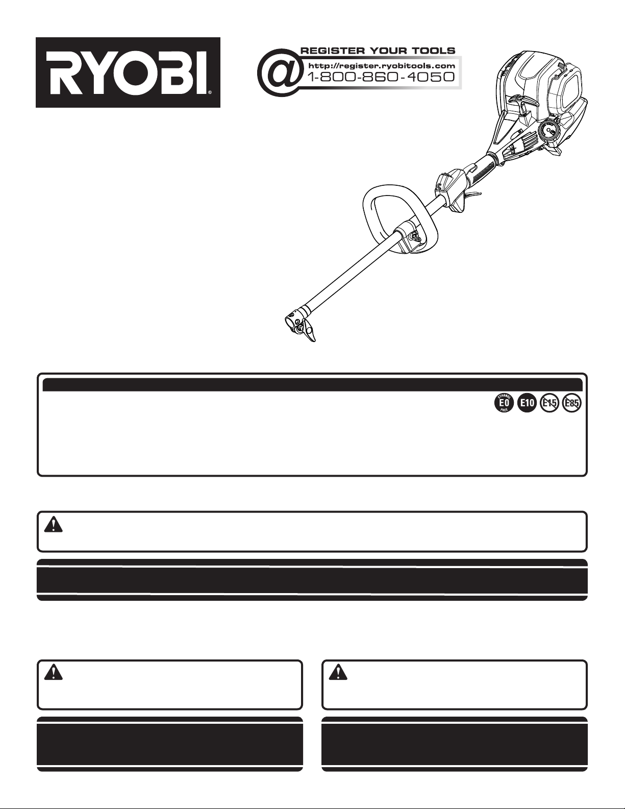
Fig. 1
F
B
E
D
C
G
H
A
K
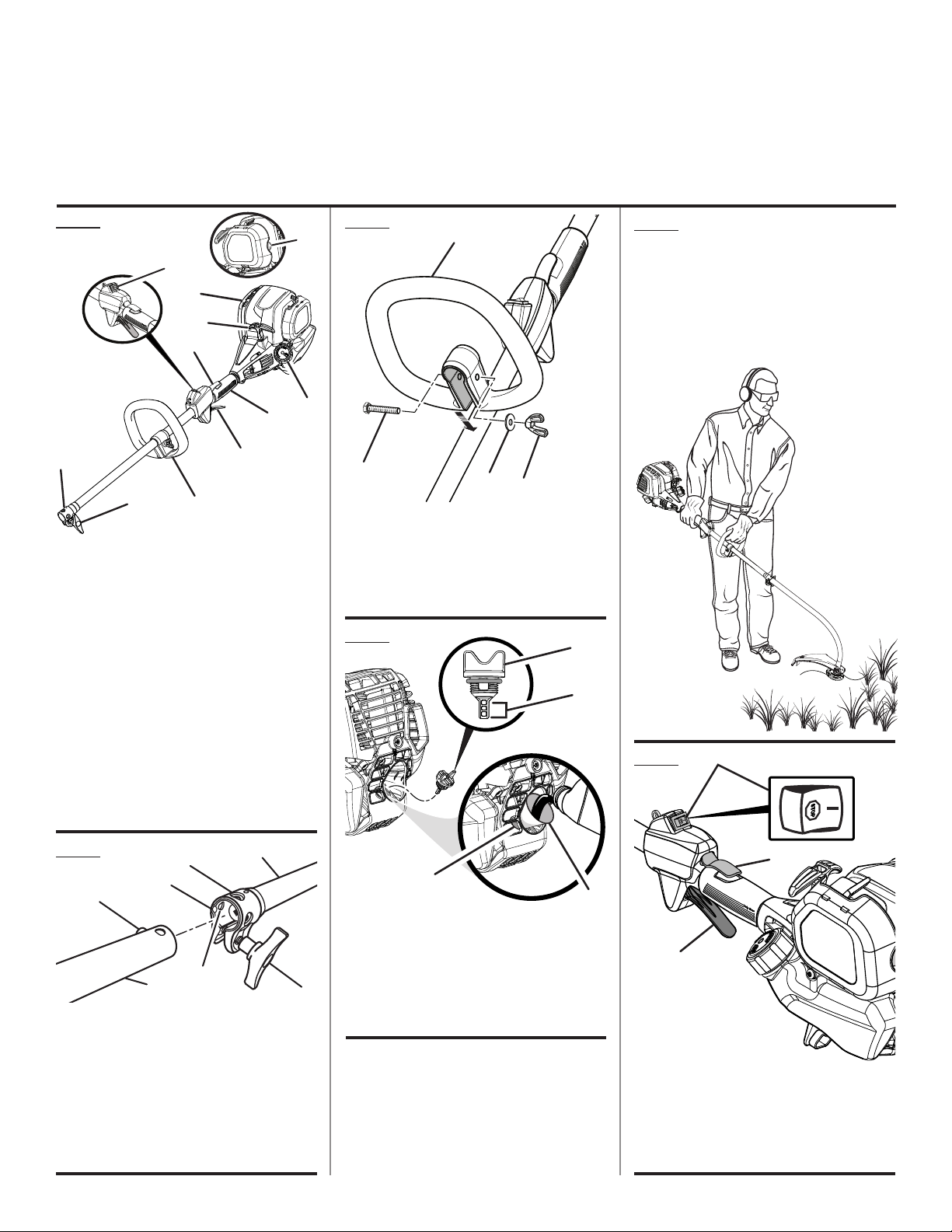
A - Coupler (coupleur, acoplador)
B - Stop switch (commutateur d’arrêt, interruptor
de apagado)
C - Trigger lock out (gâchette avec verrou, gatillo
con seguro)
D - Starter grip and rope (poignée du lanceur et
corde, mango del arrancador y cuerda)
E - Muffler (silencieux, silenciador)
F - Primer bulb (poire d’amorçage, bomba de
cebado)
G - Fuel cap (bouchon de carburant, tapa del
tanque)
H - Rear handle (poignée arrière, mango trasero)
I - Throttle trigger (gâchette d’accélérateur,
gatillo del acelerador)
J - Front handle (poignée avant, mango
delantero)
K
- Knob (bouton, perilla)
J
I
Fig. 3
B
A
A - Bolt (boulon, perno)
B - Front handle (poignée avant, mango
delantero)
C - Washer (rondelle, arandela)
D - Wing nut (écrou papillon, tuerca de
mariposa)
Fig. 4
C
D
A
B
Fig. 5
PROPER TRIMMER ATTACHMENT
OPERATING POSITION
ACCESSOIRE TAILLE-BORDURE
POSITION DE TRAVAIL
POSICIÓN CORRECTA PARA EL MANEJO
DE ADITAMENTO PARA RECORTAR
Fig. 6
A
Fig. 2
C
D
B
A
G
A - Button (bouton, botón)
B - Guide recess (logement guide, hueco guía)
C - Coupler (coupleur, acoplador)
D - Power head shaft (arbre du bloc moteur, eje
del cabezal motor)
E - Knob (bouton, perilla)
F - Positioning hole (trou de positionnement,
orificio de posicionamiento)
G - Attachment shaft (arbre d’accessoire, eje del
aditamento)
F
E
C
D
A - Oil cap/dipstick (bouchon/jauge d’huile, tapa
de aceite/varilla para medir el aceite)
B - Hatched area (zone hachurée, área cubierta
con rayas entrecruzadas)
C - Oil fill hole (orifice de remplissage d’huile,
agujero de llenado de aceite)
D - Funnel (entonnoir, embudo)
ii
B
C
A - Stop switch (commutateur d’arrêt, interruptor
de apagado)
B - Trigger lock out (gâchette avec verrou, gatillo
con seguro)
C - Throttle trigger (gâchette d’accélérateur,
gatillo del acelerador)
FULL
CHOKE
RUN
HALF
CHOKE
1. PRESS PRIMER BULB 10X
2. SET TO
3. PULL UNTIL UNIT ATTEMPTS
TO START (MAX 4X)
(DO NOT PULL THROTTLE TRIGGER)
4. SET TO
5. PULL UNTIL UNIT STARTS
6. WAIT 10 SECONDS
7. SET TO
FULL CHOKE
HALF CHOKE
RUN
Fig. 7
A
Fig. 10
C
B
D
B
Fig. 13
A
D
C
A - Stop switch (commutateur d’arrêt, interruptor
de apagado)
B - Trigger lock out (gâchette avec verrou, gatillo
con seguro)
C - Primer bulb (poire d’amorçage, bomba
de cebado)
D - Throttle trigger (gâchette d’accélérateur,
gatillo del acelerador)
Fig. 8
A - Full choke position (position de
B - Choke lever (levier de volet de départ,
C - Run position (position de marche , posición
Fig. 9
RUN
HALF
CHOKE
A
FULL
CHOKE
1. PRESS PRIMER BULB 10X
2. SET TO
3. PULL UNTIL UNIT ATTEMPTS
TO START (MAX 4X)
(DO NOT PULL THROTTLE TRIGGER)
4. SET TO
5. PULL UNTIL UNIT STARTS
6. WAIT 10 SECONDS
7. SET TO
RUN
C
HALF
CHOKE
FULL
CHOKE
1. PRESS PRIMER BULB 10X
2. SET TO
3. PULL UNTIL UNIT ATTEMPTS
TO START (MAX 4X)
(DO NOT PULL THROTTLE TRIGGER)
4. SET TO
5. PULL UNTIL UNIT STARTS
6. WAIT 10 SECONDS
7. SET TO
complètement ouvert, posición de anegación
máxima)
B
FULL CHOKE
HALF CHOKE
RUN
B
FULL CHOKE
HALF CHOKE
RUN
palanca del anegador)
de marcha)
A
A
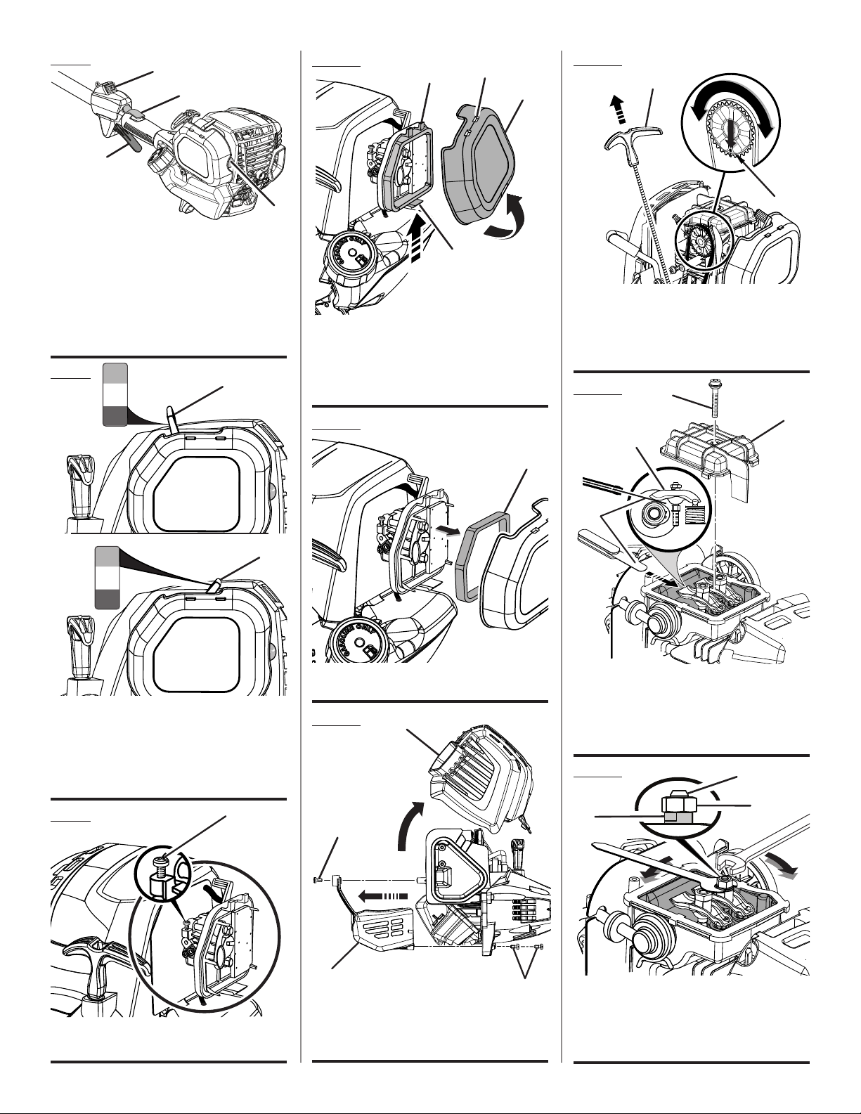
A - Latch (loquet, pestillo)
B - Air filter cover (couvercle du filtre à air, tapa
del filtro de aire)
C - Tabs (languettes, orejetas)
D - Slots (fentes, ranuras)
Fig. 11
A
A - Air filter (filtre à air, filtro de aire)
Fig. 12
A
B
B
A - Starter grip and rope (poignée du lanceur et
corde, mango del arrancador y cuerda)
B - Deep hole in camshaft gear (trou profond situé
dans l’engrenage de l’arbre à cames, orificio
profundo en el engranaje del árbol de levas)
Fig. 14
D
C
B
A
A - Feeler gauge (jauge d’épaisseur, calibrador
de separaciones)
B - Rocker arm (culbuteur, balancín)
C - Rocker arm cover (cache -culasse, tapa del
balancín)
D - Screw (vis, tornillo)
Fig. 15
C
A
B
A - Idle speed screw (vis de ralenti, tornillo de
ajuste de la velocidad en vacío)
C
A - Screw (vis, tornillo)
B - Top engine cover (couvercle moteur
supérieur, cubierta superior del motor)
C - Bottom cover (couvercle inférieure, cubierta
inferior)
A
iii
A - Retaining nut (écrou de retenue, tuerca de
retencion)
B - Adjusting nut (écrou de réglage, tuerca de
ajuste)
C - Stud (goujon, elemento estructural)

TABLE OF CONTENTS
TABLE DES MATIÈRES / ÍNDICE DE CONTENIDO
Introduction ......................................................................................................................................................................2
Introduction / Introducción
General Safety Rules ..................................................................................................................................................... 3-4
Règles de sécurité générales / Reglas de seguridad generales
Specific Safety Rules ........................................................................................................................................................ 4
Règles de sécurité particulières / Reglas de seguridad específicas
Symbols ............................................................................................................................................................................ 5
Symboles / Símbolos
Features ............................................................................................................................................................................5
Caractéristiques / Características
Assembly .......................................................................................................................................................................6-7
Assemblage / Armado
Operation .......................................................................................................................................................................7-9
Utilisation / Funcionamiento
Maintenance ................................................................................................................................................................9-12
Entretien / Mantenimiento
Troubleshooting .............................................................................................................................................................. 13
Dépannage / Solución de problemas
Warranty .........................................................................................................................................................................14
Garantie / Garantía
Parts Ordering and Service ...............................................................................................................................Back Page
Commande de pièces et réparation / Pedidos de piezas y servicio ......................................................... Page arrière / Pág. posterior
INTRODUCTION
INTRODUCTION / INTRODUCCIÓN
This product has many features for making its use more pleasant and enjoyable. Safety, performance, and dependability
have been given top priority in the design of this product making it easy to maintain and operate.
* * *
Ce produit offre de nombreuses fonctions destinées à rendre son utilisation plus plaisante et satisfaisante. Lors de la
conception de ce produit, l’accent a été mis sur la sécurité, les performances et la fiabilité, afin d’en faire un outil facile à
utiliser et à entretenir.
* * *
Este producto ofrece numerosas características para hacer más agradable y placentero su uso. En el diseño de este producto
se ha conferido prioridad a la seguridad, el desempeño y la fiabilidad, por lo cual se facilita su manejo y mantenimiento.
2

GENERAL SAFETY RULES
WARNING:
READ AND UNDERSTAND ALL INSTRUCTIONS. Failure
to follow all instructions may result in electric shock, fire
and/or serious personal injury.
READ ALL INSTRUCTIONS
For safe operation, read and understand all instructions
before using this product. Follow all safety instructions.
Failure to follow all safety instructions, can result in serious
personal injury.
Do not allow children or untrained individuals to use this
unit.
Do not start or operate the engine in a confined space,
building, near open windows, or in other unventilated space
where dangerous carbon monoxide fumes can collect.
Carbon monoxide, a colorless, odorless, and extremely
dangerous gas, can cause unconsciousness or death.
Clear the work area before each use. Remove all objects
such as rocks, broken glass, nails, wire, or loose string
which can be thrown or become entangled in the cutting
line or blade.
Always wear eye protection with side shields marked to
comply with ANSI Z87.1. Failure to do so could result in
objects being thrown into your eyes, resulting in possible
serious injury.
Wear heavy, long pants, long sleeves, boots, and gloves.
Do not wear loose fitting clothing, short pants, sandals, or
go barefoot. Do not wear jewelry of any kind.
Heavy protective clothing may increase operator fatigue,
which could lead to heat stroke. During weather that is
hot and humid, heavy work should be scheduled for early
morning or late afternoon hours when temperatures are
cooler.
Product users on United States Forest Service land, and in
some states, must comply with fire prevention regulations.
This product is equipped with a spark arrestor; however,
other user requirements may apply. Check with your federal,
state, or local authorities.
Never operate this unit on the operator’s left side.
Secure long hair above shoulder level to prevent
entanglement in moving parts.
Keep all bystanders, children, and pets at least
50 ft. away. Bystanders should be encouraged to wear
eye protection. If you are approached, stop the engine and
cutting attachment. In the case of bladed units, there is the
added risk of injury to bystanders from being struck with
the moving blade in the event of a blade thrust or other
unexpected reaction of the blade or saw chain.
Do not operate this unit when you are tired, ill, upset, or
under the influence of alcohol, drugs, or medication.
Do not operate in poor lighting.
Keep firm footing and balance. Do not overreach.
Overreaching can result in loss of balance or exposure to
hot surfaces.
Do not use on a ladder or unstable support. Stable footing
on a solid surface enables better control of the unit in
unexpected situations.
Keep all parts of your body away from any moving part.
To avoid hot surfaces, never operate the unit with the bottom
of the engine above waist level.
Do not touch area around the muffler or cylinder of the unit,
these parts get hot from operation.
Always stop the engine and remove the spark plug wire
before making any adjustments or repairs except for
carburetor adjustments.
Inspect the unit before each use for loose fasteners, fuel
leaks, etc. Replace any damaged parts before use.
Never use blades, flailing devices, wire, or rope on trimmer
attachment. Never use flailing devices, wire, or rope on any
attachment.
The cutting attachment should never rotate at idle during
normal use. The cutting attachment may rotate at idle during
carburetor adjustments.
It has been reported that vibrations from hand-held tools
may contribute to a condition called Raynaud’s Syndrome
in certain individuals. Symptoms may include tingling,
numbness, and blanching of the fingers, usually apparent
upon exposure to cold. Hereditary factors, exposure to
cold and dampness, diet, smoking, and work practices
are all thought to contribute to the development of these
symptoms. It is presently unknown what, if any, vibrations
or extent of exposure may contribute to the condition. There
are measures that can be taken by the operator to possibly
reduce the effects of vibration:
a) Keep your body warm in cold weather. When operating
the unit wear gloves to keep hands and wrists warm. It is
reported that cold weather is a major factor contributing
to Raynaud’s Syndrome.
b) After each period of operation, exercise to increase
blood circulation.
c) Take frequent work breaks. Limit the amount of
exposure per day.
d) Keep the tool well maintained, fasteners tightened, and
worn parts replaced.
If you experience any of the symptoms of this condition,
immediately discontinue use and see your physician about
these symptoms.
Store fuel in a container approved for gasoline.
Fuel and refuel outdoors where there are no sparks or
flames. Wipe up any fuel spillage. Move 30 ft. away from
refueling site before starting engine. Slowly remove the fuel
cap after stopping engine. Do not smoke when refueling.
Stop the engine and allow to cool before refueling or storing
the unit.
3 — English

GENERAL SAFETY RULES
Allow the engine to cool; empty the fuel tank and secure
the unit from moving before transporting in a vehicle.
Wear your protective equipment and observe all safety
instructions. For units equipped with a clutch, be sure
SPECIFIC SAFETY RULES
This product is intended for infrequent use by homeown-
ers and other occasional users for such general applications as trimming light and heavy vegetation, etc. It is not
intended for prolonged use. Prolonged periods of operation can cause circulatory problems in the user’s hands
due to vibration. For such use, it may be appropriate to
use a product having an anti-vibration feature.
SPECIFIC SAFETY RULES FOR TRIMMER USE
Inspect before use. Replace damaged parts. Make sure
fasteners are in place and secure. Check for fuel leaks.
Replace string head if cracked, chipped, or damaged
in any way. Be sure the string head or blade is properly
installed and securely fastened. Failure to do so can cause
serious injury.
Make sure all guards, straps, deflectors, and handles are
properly and securely attached.
Use only the manufacturer’s replacement line in the
cutting head. Do not use any other cutting attachment.
To install any other brand of replacement line or cutting
head to this string trimmer can result in serious personal
injury. Never use, for example, wire or wire-rope, which
can break off and become a dangerous projectile.
Never operate unit without the grass deflector in place
and in good condition.
Never use blades, flailing devices, wire, or rope on trimmer
attachment.
Maintain a firm grip on both handles while trimming. Keep
string head below waist level. Never cut with the string
head located over 30 in. or more above the ground.
SPECIFIC SAFETY RULES FOR BRUSH
CUTTER AND BLADE USE
Brush cutter blades coast after throttle trigger is released
or engine is stopped. Keep the rotating blade in thicker
weeds or pulpy stalks until the blade completely stops.
Do not operate the brush cutter unless the brush cutter
guard is firmly secured in place and in good condition.
Use heavy gloves when operating the brush cutter and
when installing or removing blades.
Always stop the engine and remove the spark plug wire
before attempting to remove any obstruction caught or
the cutting attachment stops turning when the engine
idles. When the unit is turned off make sure the cutting
attachment has stopped before the unit is set down.
jammed in the blade or before removing and installing
the blade.
Do not attempt to touch or stop the blade when it is
rotating.
A coasting blade can cause injury while it continues
to spin after the engine is stopped or throttle trigger
released. Maintain proper control until the blade has
completely stopped rotating.
Replace any blade that has been damaged. Always make
sure blade is installed correctly and securely fastened
before each use. Failure to do so can cause serious injury.
Use only the manufacturer’s replacement Tri-Arc® blade
intended for use on this brush cutter. Do not use any other
blade. To install any other brand blade or cutting head to
this brush cutter can result in serious personal injury.
The Tri-Arc® blade is suited for cutting thicker weeds or
pulpy stalks only. Do not use for any other purpose. Never
use the Tri-Arc® blade to cut woody brush.
Exercise extreme caution when using the blade with this
unit. Blade thrust is the reaction that may occur when
the spinning blade contacts anything it cannot cut. This
contact may cause the blade to stop for an instant, and
suddenly “thrust” the unit away from the object that was
hit. This reaction can be violent enough to cause the
operator to lose control of the unit. Blade thrust can occur
without warning if the blade snags, stalls, or binds. This is
more likely to occur in areas where it is difficult to see the
material being cut. For cutting ease and safety, approach
the weeds being cut from the right to the left. In the event
an unexpected object or woody stock is encountered,
this could minimize the blade thrust reaction.
Never cut any material over 1/2 in. diameter.
Always wear the shoulder harness when using the brush
cutter and adjust to a comfortable operating position.
Maintain a firm grip on both handles while cutting with a
blade. Keep the blade away from your body and below
waist level.
Never use the brush cutter with the blade located 30 in.
or more above the ground level.
Save these instructions. Refer to them frequently and use
them to instruct others who may use this tool. If you loan
someone this tool, loan them these instructions also.
NOTE: ADDITIONAL SPECIFIC SAFETY RULES CAN BE FOUND
IN THE APPLICABLE ATTACHMENT’S OPERATOR’S MANUAL
4 — English

SYMBOLS
The following signal words and meanings are intended to explain the levels of risk associated with this product.
SYMBOL SIGNAL MEANING
DANGER:
WARNING:
CAUTION:
NOTICE:
Some of the following symbols may be used on this product. Please study them and learn their meaning for safe
operation of this product.
SYMBOL NAME EXPLANATION
Safety Alert Indicates a potential personal injury hazard.
Read Operator’s Manual
Eye and Hearing Protection
Indicates an imminently hazardous situation, which, if not avoided, will result in
death or serious injury.
Indicates a potentially hazardous situation, which, if not avoided, could result in
death or serious injury.
Indicates a potentially hazardous situation, which, if not avoided, may result in
minor or moderate injury.
(Without Safety Alert Symbol) Indicates important information not related to an
injury hazard, such as a situation that may result in property damage.
To reduce the risk of injury, user must read and understand operator’s manual before using this product.
Always wear eye protection with side shields marked to
comply with ANSI Z87.1, along with hearing protection.
Head protection may also be required depending on the
type of attachment used and as prescribed in the attachment’s Operator’s Manual.
Keep Bystanders Away Keep all bystanders at least 50 ft. away.
Ricochet
Thrown objects can ricochet and result in personal injury
or property damage.
FEATURES
PRODUCT SPECIFICATIONS
Weight - (without fuel) .................................................................................................................................................. 9.5 lbs.
Engine displacement ......................................................................................................................................................30cc
Engine lubricant volume ................................................................................................................................................. 65 ml
KNOW YOUR PRODUCT
See Figure 1.
The safe use of this product requires an understanding of
the information on the tool and in this operator’s manual
as well as a knowledge of the project you are attempting.
Before use of this product, familiarize yourself with all operating features and safety rules, in both this manual and the
operator’s manuals for all attachments that your are using
with this power head.
5 — English
ERGONOMIC DESIGN
The design of the product provides for easy handling. It is
designed for comfort and ease of grasp when operating in
different positions and at different angles.
TOP-MOUNTED ENGINE
The top mounted engine improves balance and is located
away from the dust and debris of the cutting area.

ASSEMBLY
UNPACKING
This product requires assembly.
Carefully remove the product and any accessories from
the box. Make sure that all items listed in the packing list
are included.
WARNING:
Do not use this product if any parts on the packing list
are already assembled to your product when you unpack
it. Parts on this list are not assembled to the product by
the manufacturer and require customer installation. Use
of a product that may have been improperly assembled
could result in serious personal injury.
Inspect the product carefully to make sure no breakage
or damage occurred during shipping.
Do not discard the packing material until you have carefully
inspected and satisfactorily operated the product.
If any parts are damaged or missing, please call
1-800-860-4050 for assistance.
PACKING LIST
Power Head
Front Handle with Hardware
Bottle of 4-Cycle Lubricant
Paper Funnel
Operator’s Manual
WARNING:
If any parts are damaged or missing do not operate this
product until the parts are replaced. Use of this product
with damaged or missing parts could result in serious
personal injury.
WARNING:
Do not attempt to modify this product or create accessories not recommended for use with this product. Any
such alteration or modification is misuse and could result
in a hazardous condition leading to possible serious
personal injury.
WARNING:
To prevent accidental starting that could cause serious
personal injury, always disconnect the engine spark plug
wire from the spark plug when assembling parts.
INSTALLING AN ATTACHMENT TO THE POWER
HEAD
See Figure 2.
WARNING:
Read and understand entire Operator’s Manual for each
optional attachment used on this power head and follow
all warnings and instructions. Failure to follow all instructions may result in electric shock, fire, and/or serious
personal injury.
WARNING:
Never install, remove, or adjust any attachment while
power head is running. Failure to stop the engine can
cause serious personal injury. Never operate power head
without an attachment.
The attachment connects to the power head by means of
a coupler device.
Stop the engine and disconnect the spark plug wire.
Loosen the knob on the coupler of the power head shaft
and remove the hanger cap from the attachment shaft.
Push in the button located on the attachment shaft. Align
the button with the guide recess on the power head coupler
and slide the two shafts together. Rotate the attachment
shaft until the button locks into the positioning hole.
NOTE: If the button does not release completely in the
positioning hole, the shafts are not locked into place.
Slightly rotate from side to side until the button is locked
into place.
Tighten the knob securely.
WARNING:
Be certain the knob is fully tightened before operating
equipment; check it periodically for tightness during use
to avoid serious personal injury.
ATTACHING THE FRONT HANDLE
See Figure 3.
Remove wing nut, washer, and bolt from the front handle.
Install the front handle onto the top side of the drive shaft
housing in the area indicated by the label.
NOTE: The open side of the handle should face the
operator.
Place the bolt through the front handle.
NOTE: The hex bolt head fits inside the hex recess molded
into one side of the handle.
Reinstall the washer and wing nut.
Tighten wing nut securely.
6 — English

ASSEMBLY
REMOVING AN ATTACHMENT FROM THE
POWER HEAD
For removing or changing the attachment:
Stop the engine and disconnect the spark plug wire.
OPERATION
WARNING:
Do not allow familiarity with product to make you careless. Remember that a careless fraction of a second is
sufficient to inflict serious injury.
WARNING:
Always wear eye protection with side shields marked to
comply with ANSI Z87.1, along with hearing protection.
Head protection may also be required depending on the
type of attachment used and as prescribed in the attachment’s Operator’s Manual. Failure to do so could result in
objects being thrown into your eyes and other possible
serious injuries.
Loosen the knob.
Push in the button and twist the shafts to unlock and
separate.
OXYGENATED FUELS
NOTICE:
Do not use E15 or E85 fuel (or fuel containing greater
than 10% ethanol) in this product. It is a violation of
federal law and will damage the unit and void your
warranty.
Fuel system damage or performance problems resulting
from the use of an oxygenated fuel containing more than
the percentage of oxygenates stated below are not covered
under warranty.
Ethanol. Gasoline containing up to 10% ethanol by volume
(commonly referred to as E10) is acceptable. E15 and E85
are not.
FUELING AND REFUELING THE POWER HEAD
WARNING:
Never use flailing devices, wire, or rope on this product.
Do not use any attachments or accessories not recommended by the manufacturer of this product. The use of
attachments or accessories not recommended can result
in serious personal injury.
WARNING:
Operation of this equipment could create sparks that
can start fires around dry vegetation. A spark arrestor
may be required. The operator should contact local fire
agencies for laws or regulations relating to fire prevention
requirements.
WARNING:
Gasoline and its vapors are highly flammable and explosive. To prevent serious personal injury and property
damage, handle it with care. Keep away from ignition
sources and open flames, handle outdoors only, do not
smoke and wipe up spills immediately.
Clean surface around fuel cap to prevent contamination.
Loosen fuel cap slowly by turning counterclockwise. Rest
the cap on a clean surface.
Carefully pour fuel into the tank. Avoid spillage.
Prior to replacing the fuel cap, clean and inspect the
gasket.
Immediately replace fuel cap and hand tighten by turning
it clockwise. Wipe up any fuel spillage.
7 — English

OPERATION
Move at least 30 ft. away from refueling area before starting
the product.
NOTE: It is normal for smoke to be emitted from a new
engine after first use.
WARNING:
Always shut off engine before fueling. Never add fuel to a
machine with a running or hot engine. Move at least 30 ft.
from refueling site before starting engine. Do not smoke
and stay away from open flames and sparks. Failure to
safely handle fuel could result in serious personal injury.
ADDING/CHECKING ENGINE LUBRICANT
See Figure 4.
NOTICE:
Attempting to start the engine before it has been properly
filled with lubricant will result in equipment failure.
Engine lubricant has a major influence on engine performance and service life. This unit is shipped with a 20W50
engine lubricant to assist in the break-in period. For best
operating performance, continuing to use 20W50 engine
lubricant is recommended, however, SAE 30, 10W30, or
10W40 are all acceptable lubricants to use in this product.
Always use a 4-stroke engine lubricant that meets or exceeds
the requirements for API service classification SJ. Check
lubricant level before each use.
NOTE: Non-detergent or 2-stroke engine lubricants will
damage the engine and should not be used.
To add engine lubricant:
Remove the cap and seal from lubricant bottle provided.
Unscrew the oil cap/dipstick and remove.
Using funnel provided, add entire bottle of engine lubricant
through oil fill hole.
Reinstall the oil cap/dipstick and secure.
To check engine lubricant level:
Set unit on a flat surface.
Wipe dipstick clean and re-seat in hole; do not rethread.
Remove dipstick again and check lubricant level. Lubricant
level should fall within the hatched area on the dipstick.
If level is low, add engine lubricant until the fluid level rises
to the upper portion of the hatched area on the dipstick.
Replace and secure the oil cap/dipstick.
NOTICE:
Do not overfill. Overfilling the crankcase may cause
excessive smoke, oil loss and engine damage.
OPERATING THE POWER HEAD
See Figure 5.
WARNING:
Engine housing can become hot during operation. Do not
rest or place your arm, hand, or any body part against
the engine housing during operation. Only hold the unit
as shown in Figure 5 during trimmer operation with all
body parts clear of engine housing (or as shown in the
applicable attachment Operator’s Manual). Extended
contact with the engine housing can result in burns or
other injuries.
WARNING:
Always position the unit on the operator’s right side. The
use of the unit on the operator’s left side will expose the
user to hot surfaces and can result in possible burn injury.
WARNING:
To avoid burns from hot surfaces, never operate unit with
the bottom of the engine above waist level.
Hold the power head with your right hand on the rear handle
and your left hand on the front handle. Keep a firm grip with
both hands while in operation. Power head should be held at
a comfortable position with the rear handle about hip height.
Always operate power head at full throttle. If debris becomes
wrapped around the attachment, STOP THE ENGINE,
disconnect the spark plug wire, and remove the debris.
Prolonged cutting at partial throttle will result in lubricant
dripping from the muffler.
WARNING:
Always hold the power head away from the body keeping
clearance between the body and the product. Any
contact with the attachment cutting head can result in
burns and/or other serious personal injury.
WARNING:
Extreme care must be taken when using a blade attachment
to ensure safe operation. Read the safety information for safe
operation when using a blade attachment and refer to the
safety rules and instructions in your attachment manual.
Improper operation of a blade or any attachment could
result in serious injury.
8 — English

OPERATION
BLADE THRUST
Exercise extreme caution when using a blade attachment
with this unit. Blade thrust is the reaction that may occur
when the spinning blade contacts anything it cannot cut.
This contact may cause the blade to stop for an instant, and
suddenly “thrust” the unit away from the object that was hit.
This reaction can be violent enough to cause the operator
to lose control of the unit. Blade thrust can occur without
warning if the blade snags, stalls, or binds. This is more likely
to occur in areas where it is difficult to see the material being
cut. For cutting ease and safety, approach the weeds being
cut with the brush cutter from the right to the left. In the event
an unexpected object or woody stock is encountered, this
practice could minimize the blade thrust reaction.
STARTING AND STOPPING
See Figures 6 - 8.
Trimmer should be on a flat, bare surface for starting.
To start a cold engine:
Slowly press the primer bulb 10 times.
NOTE: After the 7th press, fuel should be visible in the
primer bulb. If it is not, continue to press the primer until
you see fuel in the bulb.
Set the choke lever to the FULL CHOKE position.
NOTE: Do not squeeze the throttle trigger.
Pull the starter grip until the engine runs.
NOTE: If engine has not started after 3 pulls and:
outside temperature is 60°F or lower, leave the choke
in the FULL CHOKE position and continue to pull the
starter grip until the engine runs.
outside temperature is above 60°F, move the choke
to the HALF CHOKE position and continue to pull the
starter grip until the engine runs.
Allow the engine to run for 10 seconds, then set the choke
lever to the RUN position.
To restart a warm engine:
Slowly press the primer bulb 10 times.
Set the choke lever to the RUN position.
Pull the starter grip until the engine runs. Do not squeeze
the throttle trigger.
To stop the engine:
To stop the engine, depress the STOP switch to the stop
position “ ”.
IF ASSISTANCE IS REQUIRED FOR THIS PRODUCT:
Do not return this product to the retail store where it was
purchased. Please call our Customer Service Department
for any issues you may have.
For Help Call: 1-800-860-4050
MAINTENANCE
WARNING:
When servicing, use only identical replacement parts.
Use of any other parts can create a hazard or cause
product damage.
WARNING:
Always wear eye protection with side shields marked to
comply with ANSI Z87.1, along with hearing protection.
Head protection may also be required depending on the
type of attachment used and as prescribed in the attachment’s Operator’s Manual. Failure to do so could result in
objects being thrown into your eyes and other possible
serious injuries.
WARNING:
Before inspecting, cleaning, or servicing the machine,
shut off engine, wait for all moving parts to stop, and
disconnect spark plug wire and move it away from spark
plug. Failure to follow these instructions can result in
serious personal injury or property damage.
GENERAL MAINTENANCE
Avoid using solvents when cleaning plastic parts. Most
plastics are susceptible to damage from various types of
commercial solvents and may be damaged by their use.
Use clean cloths to remove dirt, dust, lubricant, grease, etc.
WARNING:
Do not at any time let brake fluids, gasoline, petroleumbased products, penetrating lubricants, etc., come in contact with plastic parts. Chemicals can damage, weaken or
destroy plastic which can result in serious personal injury.
9 — English

MAINTENANCE
You can often make adjustments and repairs described
here. For other repairs, have the power head serviced by
an authorized service dealer.
IDLE SPEED ADJUSTMENT
See Figure 9.
WARNING:
The blade/cutting head will move when adjusting the
idle speed. Wear all protective clothing and keep all bystanders, children, and pets at least 50 ft. away. Make
adjustments with the unit supported by hand so that the
blade/cutting head does not contact the ground or any
object. Keep all parts of your body away from the blade/
cutting head and muffler. Failure to follow these instructions could result in serious personal injury.
If the cutting attachment turns at idle, the idle speed screw
needs adjusting on the engine. Turn the idle speed screw
counterclockwise to reduce the idle RPM and stop the cutting attachment movement. If the cutting attachment still
moves at idle speed, contact a service dealer for adjustment
and discontinue use until the repair is made.
WARNING:
The cutting attachment should never turn at idle. Turn
the idle speed screw counterclockwise to reduce the
idle RPM and stop the cutting attachment, or contact a
service dealer for adjustment and discontinue use until
the repair is made. Serious personal injury can result from
the cutting attachment turning at idle.
CLEANING THE AIR FILTER
See Figures 10 - 11.
For proper performance and long life, keep air filter screen
clean.
Remove the air filter cover. To remove, push up on the
latch at the bottom of the cover and gently pull the cover
up.
Remove the air filter.
Clean the foam filter element with warm soapy water.
Rinse and let dry.
NOTE: If the foam filter element is damaged, it should be
replaced.
Apply a light coat of engine oil to the foam filter element,
then squeeze it out.
Reinstall the air filter.
NOTE: Make sure the filter is seated properly inside the
cover. Installing the filter incorrectly will allow dirt to enter
the engine, causing rapid engine wear.
Replace the air filter cover by placing the slots on the air
filter cover over the tabs on the housing, then push the
cover down until it latches securely in place.
FUEL CAP, TANK, AND LINES
WARNING:
Check for fuel leaks. A leaking fuel cap, tank, or lines
are a fire hazard and must be replaced immediately. If
you find any leaks, correct the problem before using the
product. Failure to do so could result in a fire that could
cause serious personal injury.
The fuel cap contains a non-serviceable filter and a check
valve. A clogged fuel filter will cause poor engine performance. If performance improves when the fuel cap is loosened, check valve may be faulty or filter clogged. Replace
fuel cap if required.
SPARK PLUG REPLACEMENT
This engine uses a Champion RY4C or equivalent spark plug
with .025 in. electrode gap. Use an exact replacement and
replace annually.
NOTICE:
Be careful not to cross-thread the spark plug. Crossthreading will seriously damage the product.
CHANGING ENGINE LUBRICANT
See Figure 12.
WARNING:
Do not change engine lubricant while it is hot. Accidental
contact with hot engine lubricant could result in serious
burns.
For best performance, engine lubricant should be changed
after every 25 hours of operation.
To change the engine lubricant:
Stop the engine and disconnect the spark plug wire. Allow
the engine to cool completely before proceeding.
Remove the screw from the top engine cover and set
aside.
Remove the screws from the bottom of the engine cover.
Remove the bottom cover and set aside.
Remove the oil fill cap/dipstick.
Tip power head on its side and allow lubricant to drain
from the oil fill hole into an approved container.
NOTE: Drain the lubricant while the engine is still warm
but not hot. Warm lubricant will drain quickly and more
completely.
Return the power head to an upright position and refill
with lubricant following the instructions in the Adding/
Checking Engine Lubricant section previously in this
manual.
Reinstall the bottom engine cover. Replace the screws
and tighten securely.
10 — English

MAINTENANCE
Replace the screw in the top engine cover and tighten
securely.
NOTE: Used lubricant should be disposed of at an approved
disposal site. See your local retailer for more information.
ADJUSTING CAMSHAFT-TO-ROCKER ARM
CLEARANCE
See Figures 13 - 15.
Inspect the camshaft-to-rocker arm clearance after every
25 hours of operation. This should be done in a clean, dustfree environment.
NOTE: This procedure requires partial disassembly of the
engine. If you are unsure if you are qualified to perform this
operation, take the unit to an authorized service center.
Stop the engine and disconnect the spark plug wire. Allow
the engine to cool completely before proceeding.
Remove the screw from the top engine cover. Remove
engine cover and set aside.
Using a Torx screwdriver, remove the screw from the
rocker arm cover. Remove the cover and set aside.
Position camshaft by pulling the recoil starter grip just
until the deep hole in the camshaft gear is located at the
6 o’clock position as shown in figure 14.
Place the feeler gauge under each rocker arm and measure
the gap. The gap should be between .006 in. (0.15 mm)
and .008 in. (0.20 mm) for both rocker arms.
NOTE: Use a standard automotive feeler gauge. The .006
in. (0.15 mm) feeler gauge should slide between the rocker
arm and valve stem with a slight amount of resistance
but without binding. The 0.008 in. (0.20 mm) feeler gage
should not slide between the rocker arms and the cam
lobes — it should be held tight.
If the valve clearance is not between .006 in. (0.15 mm)
and .008 in. (0.20 mm), the clearance should be adjusted
as follows:
While holding a wrench on the flats of the adjusting
nut with one hand, loosen the retaining nut with a
second wrench as shown in figure 15. Take care not
to loosen the stud.
Rotate the adjusting nut until it touches the feeler
gauge. Once the gap setting is correct, hold the
wrench on the flats of the adjusting nut and retighten
the retaining nut securely.
Adjust the second rocker arm, if necessary.
Replace the rocker arm cover and screw; tighten securely.
Replace the top engine cover and screw; tighten securely.
WARNING:
Ensure all engine cover and all engine parts are completely and properly reassembled before starting engine.
Failure to correctly reassemble engine can result in serious injury or property damage.
STORING THE PRODUCT
Clean all foreign material from the product. Store idle unit
indoors in a dry, well-ventilated area that is inaccessible
to children. Keep away from corrosive agents such as
garden chemicals and de-icing salts.
Abide by all ISO and local regulations for the safe storage
and handling of gasoline.
When storing 1 month or longer:
Drain all fuel from tank into a container approved for
gasoline. Run engine until it stops.
HIGH ALTITUDE ENGINE OPERATION
Please have an authorized service center adjust this engine
if it is to be run above 2000 feet. Failure to do so may result
in poor engine performance and increased emissions. An
engine adjusted for high altitudes can not be run at 2000
feet or lower. In doing so, the engine will overheat and cause
serious engine damage. Please have an authorized service
center restore high altitude modified engines to the original
factory specification before operating below 2000 feet.
11 — English
 Loading...