

Page 1
OPERATOR’S MANUAL
MANUEL D’UTILISATION
MANUAL DEL OPERADOR
MITER SAW STAND
STAND POUR SCIE À ONGLETS
PEDESTAL PARA SIERRA
INGLETEADORA
RMS10SB
Your miter saw stand has been engineered and manufactured to our high standard for dependability, ease of operation, and
operator safety. When properly cared for, it will give you years of rugged, trouble-free performance.
WARNING: To reduce the risk of injury, the user must read and understand the operator’s manual before using
this product.
Thank you for your purchase.
SAVE THIS MANUAL FOR FUTURE REFERENCE
Cette stand pour scie à onglets a été conçue et fabriquée
conformément à nos strictes normes de fiabilité, simplicité
d’emploi et sécurité d’utilisation. Correctement entretenue, elle
vous donnera des années de fonctionnement robuste et sans
problème.
AVERTISSEMENT : Pour réduire les risques de
blessures, l’utilisateur doit lire et veiller à bien comprendre le
manuel d’utilisation avant d’employer ce produit.
Merci de votre achat.
CONSERVER CE MANUEL POUR
FUTURE RÉFÉRENCE
Su pedestal para sierra ingleteadora de pintura ha sido diseñado
y fabricado de conformidad con nuestras estrictas normas para
brindar fiabilidad, facilidad de uso y seguridad para el operador.
Con el debido cuidado, le brindará muchos años de sólido y eficiente funcionamiento.
ADVERTENCIA: Para reducir el riesgo de lesiones,
el usuario debe leer y comprender el manual del operador antes
de usar este producto.
Le agradecemos su compra.
GUARDE ESTE MANUAL PARA
FUTURAS CONSULTAS
Page 2

TABLE OF CONTENTS
Rules for Safe Operation ................................................................................................................................................. 2
Symbols ........................................................................................................................................................................... 3
Features ........................................................................................................................................................................... 4
Assembly ...................................................................................................................................................................... 5-8
Operation ......................................................................................................................................................................... 9
Maintenance .................................................................................................................................................................. 10
RULES FOR SAFE OPERATION
Safe operation of this accessory requires that you read and
understand this operator’s manual, the operator’s manual for
the table saw and all labels affixed to the tool.
READ ALL INSTRUCTIONS
Know your accessory. Read the operator’s manual care-
fully. Learn its applications and limitations, as well as the
specific potential hazards related to this accessory.
Keep the work area clean. Cluttered work areas and
work benches invite accidents.
Always wear safety glasses with side shields.
Everyday glasses have only impact resistant lenses. They
are NOT safety glasses.
This stand will accommodate many miter saws. How-
ever, it should never be used on any miter saw with a blade
diameter larger than 12 in. or with any slide miter saw with
a blade diameter larger than 10 in. Always confirm any
miter saw used is mounted securely and is stable before
plugging in the miter saw. Before turning on the saw,
perform a dry run of the cutting operation just to make
sure that no problems will occur when the cut is made.
WARNING:
Do not modify or use this stand for any purpose for
which it is not intended.
This stand is designed to be used on a flat stable
surface. Do not use the stand on an uneven surface. Be
sure to allow enough room to handle and properly support the workpiece.
Follow the tool mounting instructions carefully, and
ensure the tool is fastened securely.
Maximum weight of the miter saw and workpiece to-
gether must not exceed 300 pounds.
Do not apply an unbalanced load that could cause the
miter saw stand to tip over.
Save these instructions. Refer to them frequently and
use them to instruct others who may use this accessory.
If you loan someone this accessory, loan them these
instructions also to prevent misuse of the product and
possible injury.
This stand is designed for use with miter saws with a blade diameter not larger than 12 in., or a slide miter saw with a
blade diameter not larger than 10 in.
2 - English
Page 3
SYMBOLS
The following signal words and meanings are intended to explain the levels of risk associated with this product.
SYMBOL SIGNAL MEANING
DANGER:
WARNING:
CAUTION:
NOTICE:
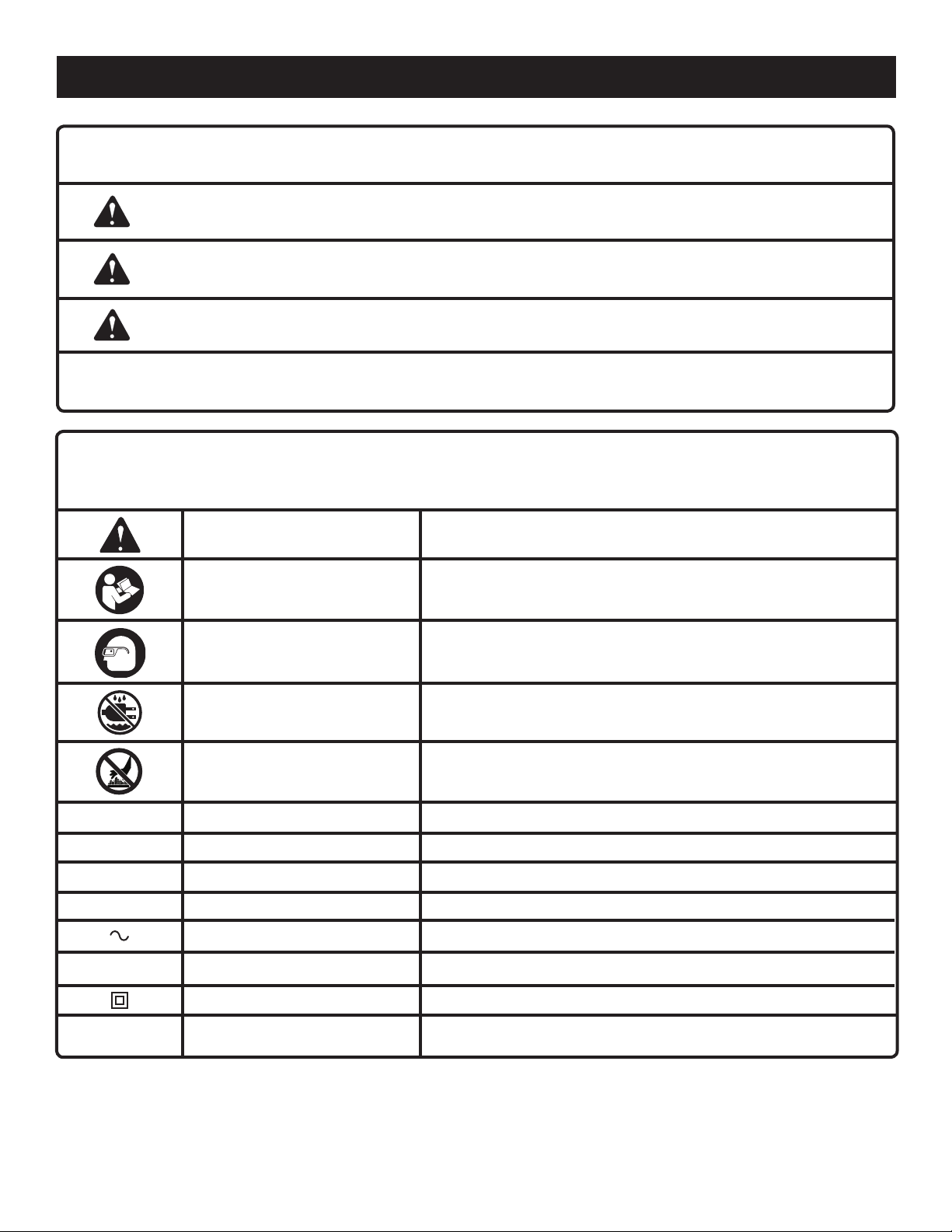
Some of the following symbols may be used on this tool. Please study them and learn their meaning. Proper
interpretation of these symbols will allow you to operate the tool better and safer.
SYMBOL NAME
Safety Alert Indicates a potential personal injury hazard.
Read Operator’s Manual
Eye Protection
Indicates an imminently hazardous situation, which, if not avoided, will result
in death or serious injury.
Indicates a potentially hazardous situation, which, if not avoided, could result
in death or serious injury.
Indicates a potentially hazardous situation, which, if not avoided, may result in
minor or moderate injury.
(Without Safety Alert Symbol) Indicates important information not related to an
injury hazard, such as a situation that may result in property damage.
DESIGNATION/EXPLANATION
To reduce the risk of injury, user must read and understand operator’s manual before using this product.
Always wear eye protection with side shields marked to comply
with ANSI Z87.1.
Wet Conditions Alert Do not expose to rain or use in damp locations.
Hot Surface
V Volts Voltage
A Amperes Current
Hz Hertz Frequency (cycles per second)
min Minutes Time
Alternating Current Type of current
n
o
.../min Per Minute Revolutions, strokes, surface speed, orbits, etc., per minute
No Load Speed Rotational speed, at no load
Class II Construction Double-insulated construction
To reduce the risk of injury or damage, avoid contact with any hot
surface.
3 - English
Page 4
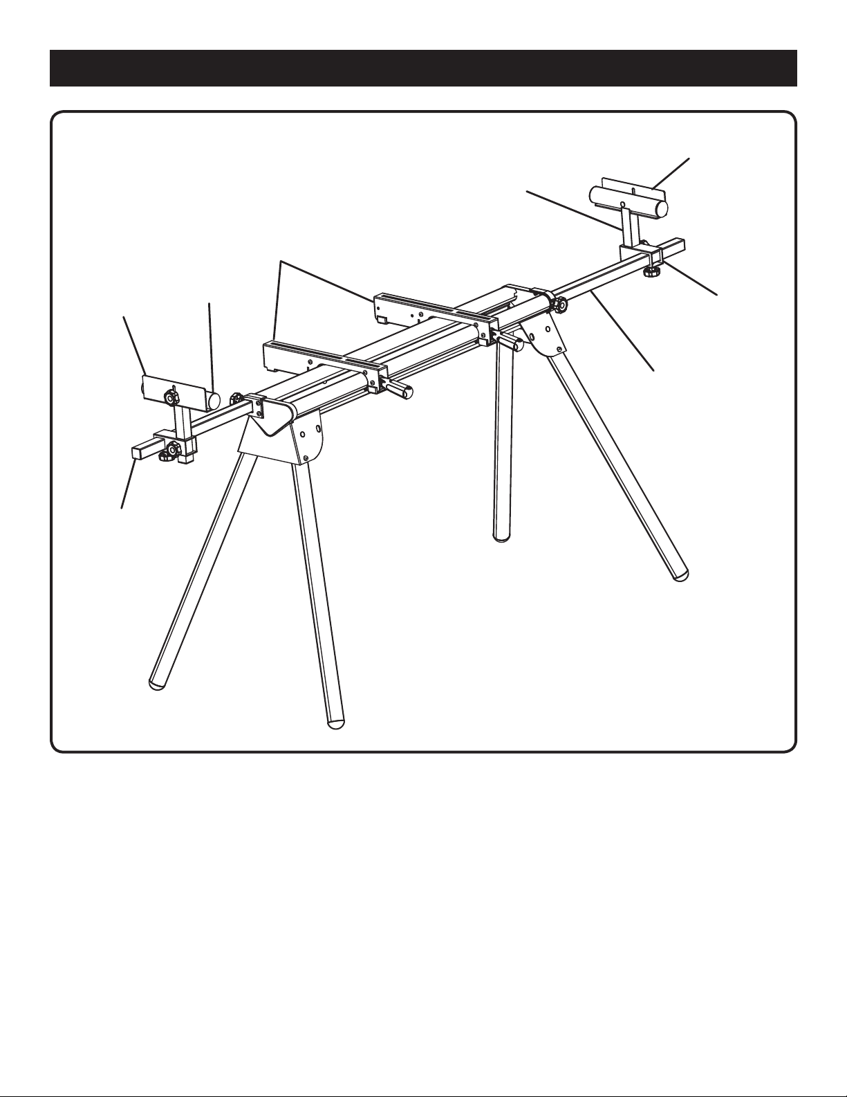
SAW MOUNTING
BRACKET
FEATURES
WORK
STOP
WORK
SUPPORT
WORK
STOP
EXTENSION
RAIL
WORK
SUPPORT
WORK
SUPPORT
MOUNTING
BRACKET
EXTENSION
RAIL
4 - English
Fig. 1
Page 5
ASSEMBLY
UNPACKING
This product requires some assembly.
Carefully remove the tool and any accessories from the
box. Make sure that all items listed in the packing list are
included.
WARNING:
Do not use this product if it is not completely assembled
or if any parts appear to be missing or damaged. Use of
a product that is not properly and completely assembled
could result in serious personal injury.
Inspect the tool carefully to make sure no breakage or
damage occurred during shipping.
Do not discard the packing material until you have care-
fully inspected and satisfactorily operated the tool.
If any parts are damaged or missing, please call
1-800-525-2579 for assistance.
WARNING:
If any parts are damaged or missing do not operate this
product until the parts are replaced. Use of this product
with damaged or missing parts could result in serious
personal injury.
WARNING:
Do not attempt to modify this tool or create accessories not recommended for use with this tool. Any such
alteration or modification is misuse and could result in a
hazardous condition leading to possible serious personal
injury.
PACKING LIST
Miter Saw Stand
Saw Mounting Brackets (2)
Work Supports (2)
Work Support Mounting Brackets (2)
Work Stops (2)
Extension Adjustment Knobs (M8 x 24 mm) (2)
Length Adjustment Knobs (M8 x 18 mm) (2)
Height Adjustment Knobs (M8 x 18 mm) (2)
Work Stop Adjustment Knobs (2)
Carriage Bolts (M6 x 55 mm) (2)
Carriage Bolts (M8 x 45 mm) (4)
Carriage Bolts (M6 x 45 mm) (4)
Flat Washers (8)
Lock Washers (8)
Nuts (8)
Operator’s Manual
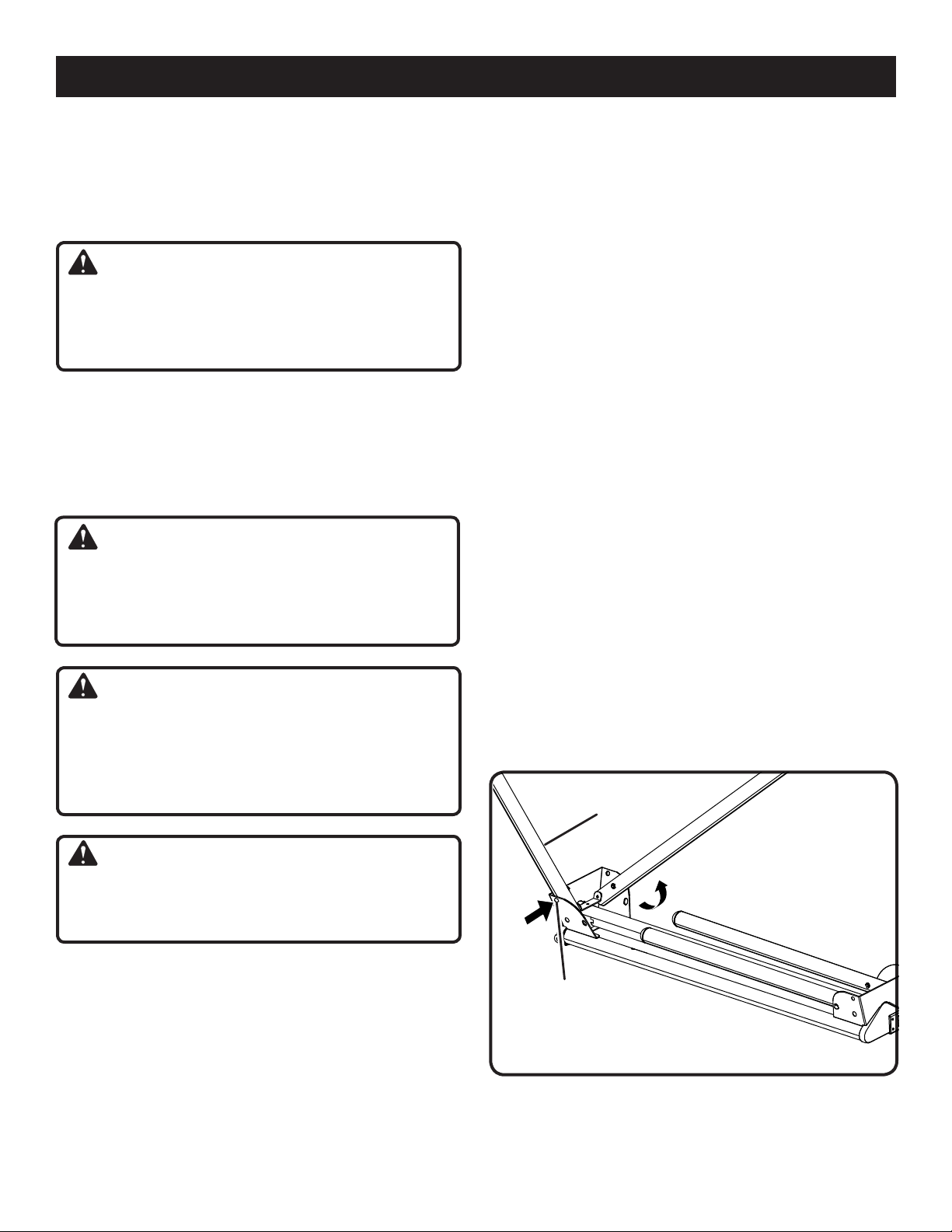
PREPARING THE STAND
See Figure 2.
Lay the stand’s top surface down on the floor with the
folded legs on top.
Push in a leg locking pin and rotate that leg up until the
locking pin clicks into place.
Repeat with the remaining three legs.
Lift the stand and place it in an upright position.
Check to ensure the stand is stable and all the legs have
the locking pins engaged.
LEG
WARNING:
Do not connect to power supply until assembly is
complete. Failure to comply could result in accidental
starting and possible serious personal injury.
5 - English
LOCKING
PIN
Fig. 2
Page 6
ASSEMBLY
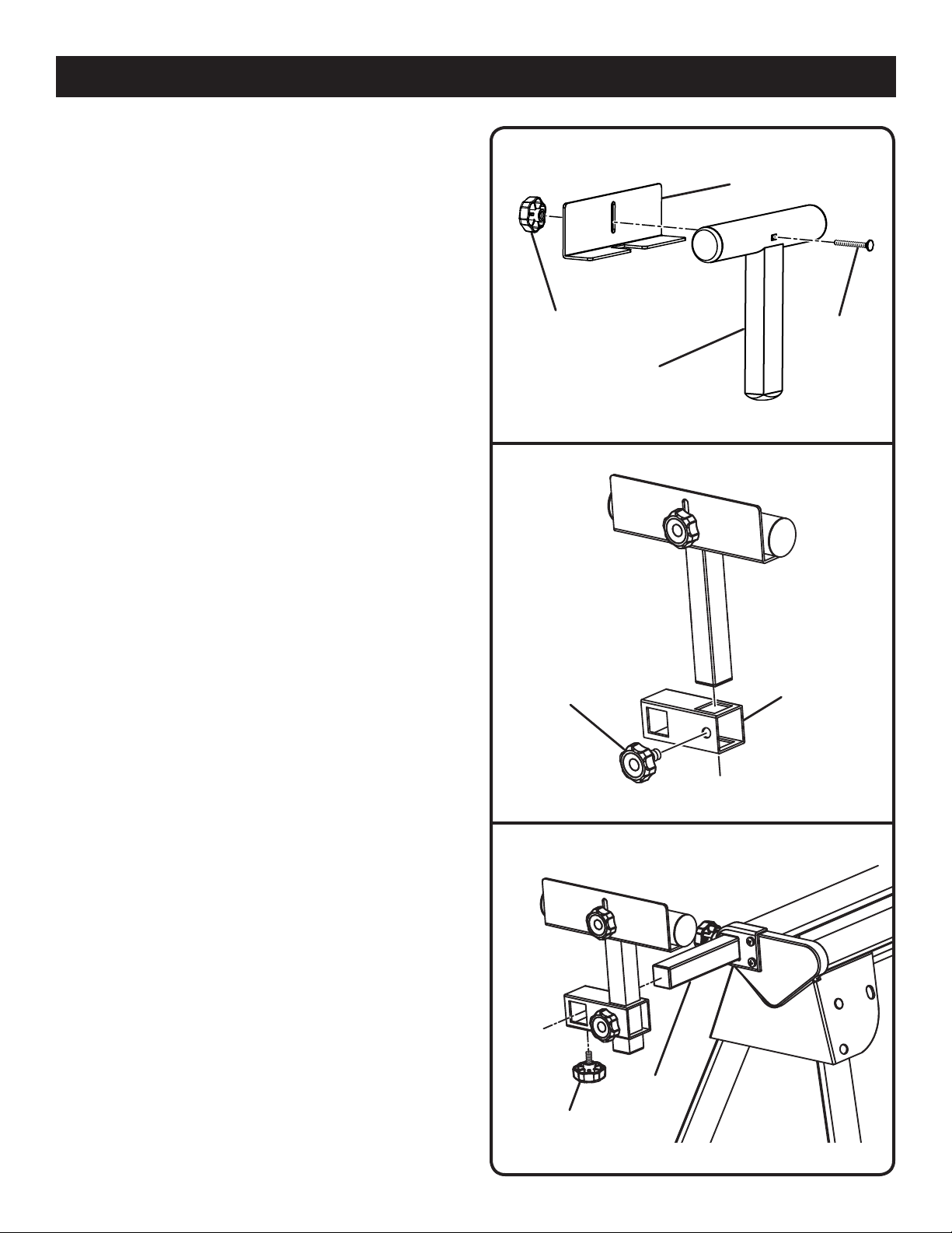
ASSEMBLING AND INSTALLING MATERIAL
WORK SUPPORTS
See Figures 3 - 5.
The material work supports help balance the workpiece
during cutting operations.
To assemble the work support:
Slide a carriage bolt (M6 x 55 mm) through the square
hole in the work support and extend through the other
side.
Place the work stop over the end of the bolt
Thread a work stop adjustment knob over the end of the
bolt and tighten to secure.
Slide the work support rail through the hole in the top of
the work support mounting bracket.
Insert the height adjustment knob through the small hole
on the side of the work support mounting bracket and
tighten to secure.
To install the work supports:
Slide the work support mounting bracket over the exten-
sion rail so that the extension rail extends through the
opening in the bracket. Position the work support at the
desired location on the extension rail.
Insert a length adjustment knob through the opening in
the bottom of the work support mounting bracket and
tighten to secure.
Repeat with the other support.
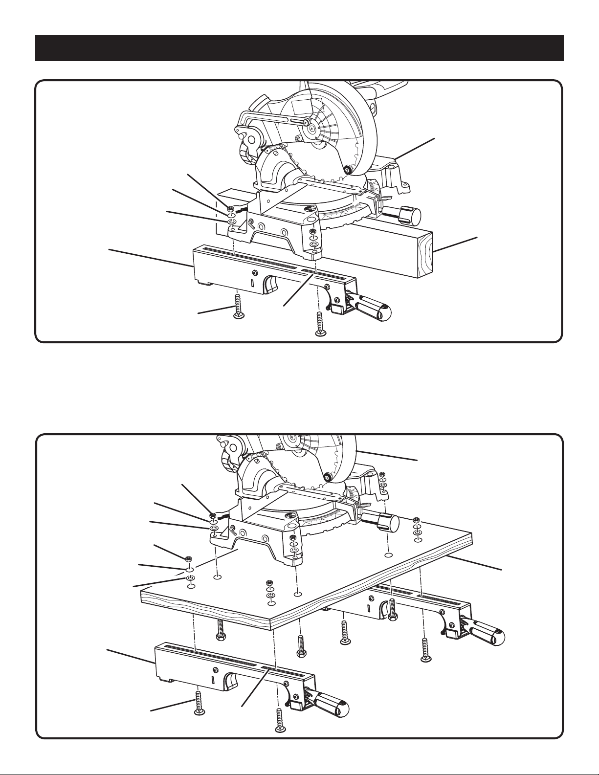
ATTACHING SAW MOUNTING BRACKETS
See Figures 6 - 7.
Always position the saw to achieve maximum balance and
stability. All four corners of the saw must be bolted to the
mounting brackets before use. Make sure bolts do not extend
above the table of the miter saw.
If the saw has holes that line up with the slots in the saw
mounting brackets:
Unplug the saw and lock the saw arm in the down
position.
Place a 2 x 4 or similar type of stable support underneath
the saw to raise the saw and allow access to the saw’s
mounting feet.
Place a saw mounting bracket underneath the raised side
of the saw, aligning the mounting holes on the miter saw
base with the slot in the top of the bracket.
Feed a carriage bolt up through both the bracket and a
mounting hole in the saw.
Secure in place using a flat washer, lock washer and
nut.
Repeat through the other end of the same bracket.
Place the second saw mounting bracket underneath the
other side of the saw, aligning the mounting holes on the
miter saw base with the opening in the bracket.
WORK STOP
ADJUSTMENT KNOB
SUPPORT
HEIGHT
ADJUSTMENT KNOB
LENGTH
ADJUSTMENT KNOB
WORK
STOP
CARRIAGE
BOLT
WORK
Fig. 3
WORK SUPPORT
MOUNTING
BRACKET
Fig. 4
EXTENSION
RAIL
Fig. 5
6 - English
Page 7
LOCK WASHER
FLAT WASHER
ASSEMBLY
MITER
SAW
NUT
SAW MOUNTING
BRACKET
CARRIAGE
BOLT
Install carriage bolts as previously described.
After making sure both brackets are parallel to each other,
finger tighten all four nuts to hold in position.
If the saw has holes that do not line up with the slots in
the saw mounting brackets:
Unplug the saw and lock saw arm in the down position.
NUT
LOCK WASHER
SLOT
2 x 4
Fig. 6
Mount the saw to a mounting surface at least 1/2 in.
thick using 5/16 hex head screws, washers, and nuts
(not included).
Drill holes in the mounting surface to match the slots in
the saw mounting brackets.
Proceed with installation as previously described.
MITER SAW
FLAT WASHER
LOCK WASHER
FLAT WASHER
SAW MOUNTING
BRACKET
CARRIAGE BOLT
NUT
MOUNTING
SURFACE
SLOT
Fig. 7
7 - English
Page 8
ASSEMBLY
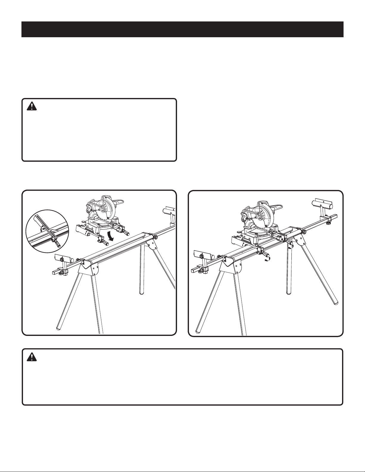
MOUNTING THE MITER SAW TO THE STAND
See Figures 8 - 9.
Lift the saw and bracket assembly, allowing the assembly
to tilt slightly toward your body.
While still tilted toward you, hook the front edge of the
bracket assembly onto the front rail of the stand.
WARNING:
To avoid serious personal injury, make sure the curved
front edge of the mounting brackets are securely seated
over the front rail before seating the other end of the
brackets. Failure to do so could cause you to lose control
of the saw mounting assembly, which could cause serious personal injury.
Lower the bracket assembly to allow the rear edge of the
bracket to seat fully over the rear rail.
Lock the brackets in position by lowering the locking
levers.
NOTE: Continue to hold the mounting bracket assembly
with one hand until both levers are securely locked.
Check position and adjust, if necessary, to make sure
the weight of the saw is evenly balanced over the rails
as shown in figure 9.
Ensure the saw is fully seated and locked in position, then
securely tighten the four nuts holding the saw to the saw
mounting brackets.
To remove saw from stand:
Raise the locking levers to unlock the saw and mounting
bracket assembly.
Lift away from the rear rail of the stand to disengage.
With the assembly tilted slightly toward you, lift the front
part of the assembly to disengage from the front rail of
the stand.
LOWER
LOCKING LEVERS
TO SECURE
TO STAND
Fig. 8
Fig. 9
WARNING:
The mounting brackets are designed to fit snugly over the stand rails. With the locking levers in the lowered (locked)
position, you should not be able to remove the saw and bracket assembly from the rails. If the mounting brackets will
not fit over the rails, or if the mounting brackets can be removed from the rails when the levers are locked, remove from
the saw and bracket assembly immediately and tighten the bracket adjustment screw as described in the Maintenance
section of this manual. Failure to heed this warning can result in serious personal injury.
8 - English
Page 9
OPERATION
WARNING:
Do not allow familiarity with tools to make you careless. Remember that a careless fraction of a second is
sufficient to inflict serious injury.
WARNING:
Always wear eye protection with side shields marked to
comply with ANSI Z87.1. Failure to do so could result in
objects being thrown into your eyes resulting in possible
serious injury.
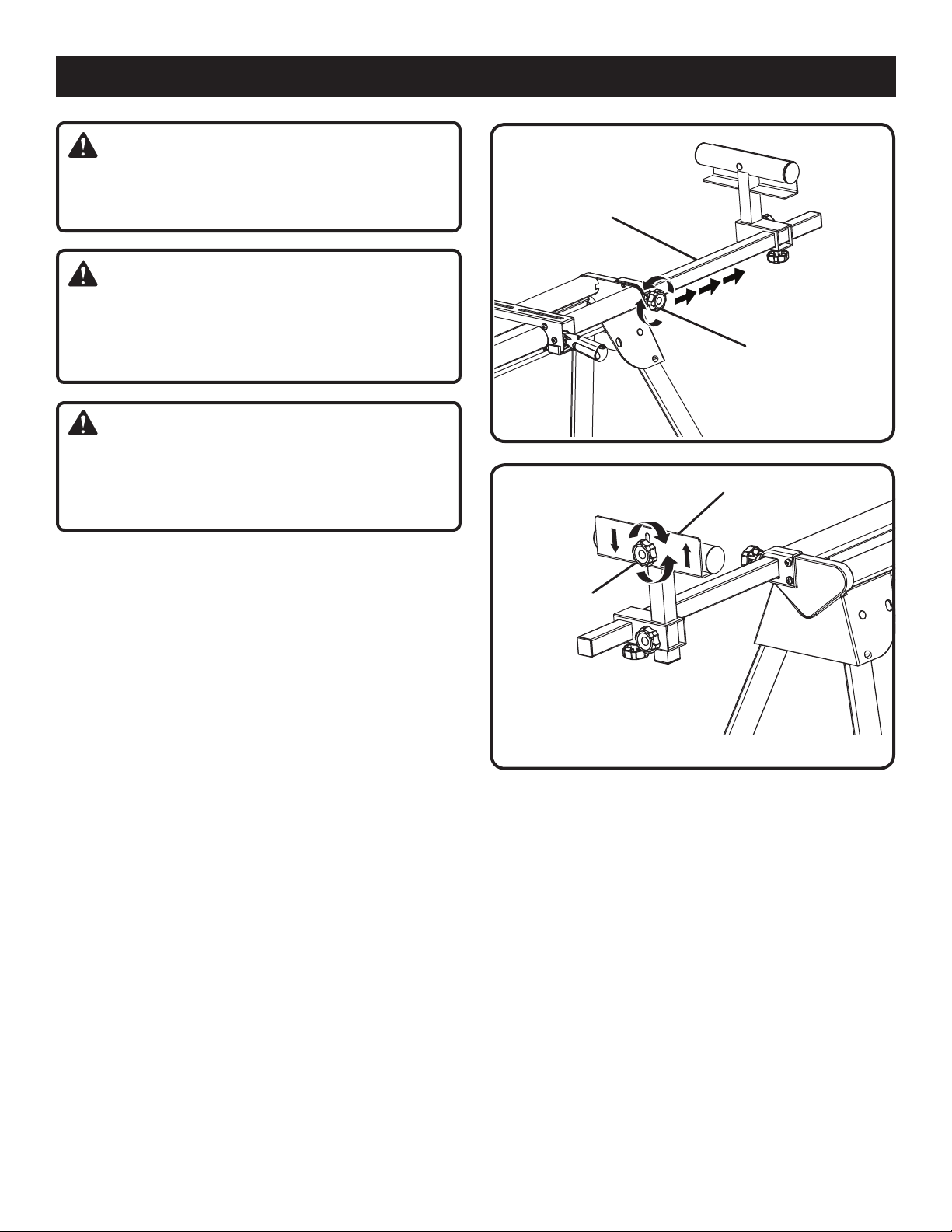
EXTENSION
RAIL
EXTENSION
ADJUSTMENT
KNOB
WARNING:
Do not use any attachments or accessories not recommended by the manufacturer of this tool. The use of attachments or accessories not recommended can result
in serious personal injury.
APPLICATIONS
You may use this tool for the following purpose:
To provide a stable, secure work surface for a miter
saw
USING THE EXTENSION RAILS
See Figure 10.
Use the extension rails when working with larger workpieces.
To extend the rails:
Loosen the extension adjustment knob.
Extend the rail to the desired position.
Tighten the extension adjustment knob.
USING THE WORK STOPS
See Figure 11.
Raise the work stops whenever you need to make repetitive
cuts of the same size. To avoid a greater risk of binding or
pinching, do not use both work stops at the same time.
To raise the work stops:
Loosen the work stop adjustment knob.
Raise the work stop to the desired position.
Tighten the work stop adjustment knob.
Fig. 10
WORK STOP
WORK STOP
ADJUSTMENT
KNOB
Fig. 11
9 - English
Page 10
MAINTENANCE
WARNING:
When servicing, use only identical replacement parts.
Use of any other parts can create a hazard or cause
product damage.
WARNING:
Always wear eye protection with side shields marked to
comply with ANSI Z87.1. Failure to do so could result in
objects being thrown into your eyes resulting in possible
serious injury.
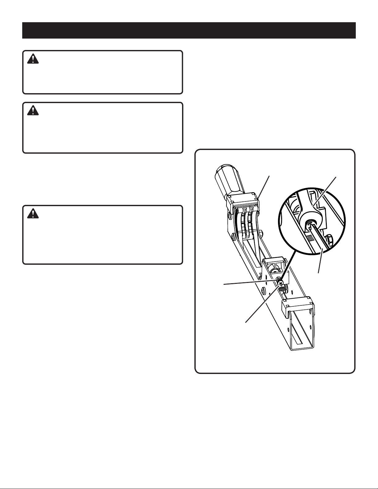
GENERAL MAINTENANCE
Avoid using solvents when cleaning plastic parts. Most
plastics are susceptible to damage from various types of
commercial solvents and may be damaged by their use. Use
clean cloths to remove dirt, dust, oil, grease, etc.
To adjust:
Use a wrench to slightly loosen the nut.
Turn the screw with a phillips screwdriver. Rotate clock-
wise if the bracket assembly needs to be tightened or
counterclockwise if the assembly needs to be loosened.
Install the bracket on the miter stand rails and lower the
locking lever to check the adjustment.
When the correct position is achieved, wrench tighten
the nut to secure.
Repeat with the second mounting bracket.
SAW
MOUNTING
BRACKET
WRENCH
WARNING:
Do not at any time let brake fluids, gasoline, petroleumbased products, penetrating oils, etc., come in contact
with plastic parts. Chemicals can damage, weaken or
destroy plastic which can result in serious personal
injury.
BRACKET ADJUSTMENT SCREW
See Figure 12.
Mounting brackets are designed to fit snugly over the stand
rails. With the locking levers in the lowered (locked) position,
you should not be able to remove the saw and bracket assembly from the rails. If the saw and bracket assembly can
be removed from the rails when the levers are locked, the
bracket adjustment screws need to be tightened. If the saw
and bracket assembly will not fit over both rails, the bracket
adjustment screws needs to be loosened.
NOTE: The saw should be removed from the mounting
brackets before attempting to tighten or loosen the bracket
adjustment screws.
SCREWDRIVER
NUT
BRACKET
ADJUSTMENT
SCREW
Fig. 12
10 - English
Page 11

TABLE DES MATIÈRES
Règles pour la sécurité d’utilisation ...........................................................................................................................................2
Symboles ...................................................................................................................................................................................3
Caractéristiques .............................................................................................................................................................. 4
Assemblage ............................................................................................................................................................................ 5-8
Utilisation ....................................................................................................................................................................................9
Entretein ...................................................................................................................................................................................10
RÈGLES POUR LA SÉCURITÉ D’UTILISATION
La sécurité d’utilisation de cet accessoire exige que ce
manuel, le manuel d’utilisation de la scie circulaire à table
ainsi que tous les autocollants apposés sur l’outil soient lus
et bien compris.
LIRE TOUTES LES INSTRUCTIONS
Apprendre à connaître l’accessoire. Lire attentivement
le manuel d’utilisation. Apprendre les applications et les
limites de l’accessoire, ainsi que les risques spécifiques
relatifs à son utilisation.
Garder le lieu de travail propre. Un lieu de travail et un
établi encombrés sont propices aux accidents.
Toujours porter des lunettes de sécurité avec écrans
latéraux. Les lunettes de vue ordinaires sont munies
seulement de verres résistants aux impacts. Ce ne sont PAS
des lunettes de sécurité.
Ce stand peut être utilisé avec de nombreuses scies
à onglet. Toute fois, il ne doit jamais être utilisé pour
une scie à onglet de quelque type que ce soit à lame de
305 mm (12 po) ni pour une scie à onglet coulissante à
lame de 254 mm (10 po). Toujours vérifier que la scie à
onglet est solidement assujettie sur le stand avant de la
brancher. Avant de mettre la scie en marche, effectuer
un essai à vide, afin de s’assurer qu’aucun problème ne
se présentera lorsque la coupe est effectuée. Le respect
de cette règle réduira les risques de blessures graves.
Ne pas modifier le stand ou l’utiliser pour des applications
pour lesquelles il n’est pas conçu.
Ce stand est conçu pour être utilisé sur une surface
plane et stable. Ne pas l’utiliser sur une surface irrégulière.
Veiller à prévoir suffisamment d’espace pour pouvoir soutenir
correctement les pièces à couper et les manipuler.
Suivre les instructions de montage à la lettre et s’assurer
que l’outil est solidement assujetti.
Le poids total de la scie et de la pièce ne doit pas dépasser
136 kg (300 lb).
Ne pas appliquer une charge en déséquilibre sur le stand,
qui risquerait de le faire basculer.
Conserver ces instructions. Les consulter fréquemment
et les utiliser pour instruire les autres utilisateurs éventuels.
Si cet accessoire est prêté, il doit être accompagné de ces
instructions, afin d’éviter un usage incorrect et d’éventuelles
blessures.
AVERTISSEMENT :
Ce stand est conçu pour être utilize avec des scies à onglets ayant un diamètre de lame inférieur à 305 mm (12 po), ou
une scie à onglets coulissante ayant un diamètre de lame inférieur à 254 mm (10 po).
2 - Françias
Page 12

SYMBOLES
Les termes de mise en garde suivants et leur signification ont pour but d’expliquer le degré de risques associé à
l’utilisation de ce produit.
SYMBOLE SIGNAL SIGNIFICATION
DANGER :
Indique une situation extrêmement dangereuse qui, si elle n’est pas
évitée, aura pour conséquences des blessures graves ou mortelles.
AVERTISSEMENT :
ATTENTION :
AVIS :
Certains des symboles ci-dessous peuvent être utilisés sur l’outil. Veiller à les étudier et à apprendre leur signification.
Une interprétation correcte de ces symboles permettra d’utiliser l’outil plus efficacement et de réduire les risques.
SYMBOLE NOM
Symbole d’alerte de sécurité Indique un risque de blessure potentiel.
Lire le manuel d’utilisation
Protection oculaire
Avertissement concernant
l’humidité
Indique une situation potentiellement dangereuse qui, si elle n’est pas
évitée, pourrait entraîner des blessures graves ou mortelles.
Indique une situation potentiellement dangereuse qui, si elle n’est pas
évitée, pourraît entraîner des blessures légères ou de gravité modérée.
(Sans symbole d’alerte de sécurité) Indique une information importante
ne concernant pas un risque de blessure comme une situation pouvant
occasionner des dommages matériels.
DÉSIGNATION / EXPLICATION
Pour réduire les risques de blessures, l’utilisateur doit lire et veiller à
bien comprendre le manuel d’utilisation avant d’utiliser ce produit.
Toujours porter une protection oculaire avec écrans latéraux
certifiée conforme à la norme ANSI Z87.1.
Ne pas exposer à la pluie ou l’humidité.
Surface brûlante
V Volts Tension
A Ampères Intensité
Hz Hertz Fréquence (cycles par seconde)
min Minutes Temps
Courant alternatif Type de courant
n
o
.../min Par minute Tours, coups, vitesse périphérique, orbites, etc., par minute
Vitesse à vide Vitesse de rotation à vide
Construction de classe II Construction à double isolation
Pour éviter les risques de blessures ou de dommages, éviter tout
contact avec les surfaces bûlantes.
3 - Françias
Page 13

BUTÉE
CARACTÉRISTIQUES
BUTÉE
SUPPORT
DE TRAVAIL
SUPPORT DE
MONTAGE
DE LA SCIE
SUPPORT
DE TRAVAIL
ÉQUERRE
DE SUPPORT
DE PIÈCE
RAIL
D’EXTENSION
RAIL
D’EXTENSION
Fig. 1
4 - Françias
Page 14

ASSEMBLAGE
UNPACKING
Ce produit a été expédié complètement assemblé.
Avec précaution, sortir l’outil et les accessoires de la
boîte. S’assurer que toutes les pièces figurant sur la liste
de contrôle sont incluses.
AVERTISSEMENT :
Ne pas utiliser le produit s’il n’est pas complètement
assemblé ou si des pièces semblent manquantes ou
endommagées. Le fait d’utiliser un produit assemblé
de façon inadéquate ou incomplète peut entraîner des
blessures graves.
Examiner soigneusement l’outil pour s’assurer que rien
n’a été brisé ou endommagé en cours de transport.
Ne pas jeter les matériaux d’emballage avant d’avoir
soigneusement examiné l’outil et avoir vérifié qu’il
fonctionne correctement.
Si des pièces sont manquantes ou endommagées,
appeler le 1-800-525-2579.
AVERTISSEMENT :
Si des pièces manquent ou sont endommagées, ne pas
utiliser cet outil avant qu’elles aient été remplacées. Le
fait d’utiliser ce produit même s’il contient des pièces
endommagées ou s’il lui manque des pièces peut
entraîner des blessures graves.
AVERTISSEMENT :
Ne pas essayer de modifier cet outil ou de créer des
accessoires non recommandés pour l’outil. De telles
altérations ou modifications sont considérées comme un
usage abusif et peuvent créer des conditions dangereuses,
risquant d’entraîner des blessures graves.
PACKING LIST
Stand pour scie à onglets
Supports de montage de la scie (2)
Supports de pièce (2)
Équerre de support de pièce (2)
Butées (2)
Bouton de réglage d’extension (M8 x 24 mm) (2)
Bouton de réglage de longueur (M8 x 18 mm) (2)
Boutons de réglage de hauteur (M8 x 18 mm) (2)
Boutons de réglage de butée (2)
Boulon de carrossier (M6 x 55 mm) (2)
Boulons de carrossier (M8 x 45 mm) (4)
Boulons de carrossier (M6 x 45 mm) (4)
Rondelles plates (8)
Rondelles frein (8)
Écrous (8)
Manuel d’utilisation
PRÉPARATION DU STAND
Voir la figure 2.
Poser le stand à l’envers sur le sol, les pieds pliants dirigés
vers le haut.
Appuyer sur la goupille de verrouillage de l’un dés pieds
et relever ce pied jusqu’à ce que la goupille s’engage
dans son trou.
Répéter la procédure pour les trois autres pieds.
Soulever le stand et le mettre à l’endroit.
Vérifier que le stand est stable et que toutes les goupilles
de verrouillage des pieds sont engagées.
PIED
AVERTISSEMENT :
Ne pas brancher sur le secteur avant d’avoir terminé
l’assemblage. Le non respect de cet avertissement peut
causer un démarrage accidentel, entraînant des blessures
graves.
5 - Françias
AXE DE
BLOCAGE
Fig. 2
Page 15

ASSEMBLAGE
ASSEMBLAGE ET INSTALLATION DES
SUPPORTS DE PIÈCE
Voir les figures 3 à 5.
Les supports aident à maintenir l’équilibre des pièces
pendant la coupe.
Assemblage des supports de pièce :
Insérer un boulon de carrossier (M6 x 55 mm) dans le trou
carré du support de pièce et le faire ressortir de l’autre
côté.
Placer le support de pièce sur le boulon.
Visser un bouton de réglage de butée sur le boulon et le
serrer.
Glisser le rail du support de pièce dans le trou de son
support de montage.
Insérer le bouton de réglage de hauteur dans le petit trou
latéral du support de pièce et le serrer.
Installation des supports de pièce :
Glisser le support sur le rail d’extension, jusqu’à ce que
ce dernier dépasse du trou du support. Positionner le
support à l’endroit désiré du rail d’extension.
Insérer un bouton de réglage de longueur dans le petit
trou inférieur du support de pièce et le serrer.
Répéter l’opération pour l’autre support.
BOUTONS
DE RÉGLAGE
DE BUTÉE
BUTÉE
BOULON DE
CARROSSIER
SUPPORT
DE TRAVAIL
Fig. 3
INSTALLATION DES SUPPORTS DE
MONTAGE DE LA SCIE
Voir les figures 6 et 7.
Toujours positionner la scie de manière à obtenir un
maximum d’équilibre et de stabilité. Avant d’utiliser la scie,
les quatre coins de sa base doivent être boulonnés sur
les supports de montage. S’assurer que les boulons ne
dépassent pas de la table de la scie.
Si la scie comporte des trous qui s’alignent sur les fentes
des supports de montage :
Débrancher la scie et verrouiller le bras en position
abaissée.
Placer un morceau de montant 2 x 4 ou un objet similaire
au-dessous de la scie pour la soulever, afin de pouvoir
accéder à ses pieds de montage.
Placer un support de montage au-dessous du côté
soulevé de la scie, en alignant les trous de montage de
la base de la scie sur la fente du dessus du support.
Insérer un boulon de carrossier dans le support et un trou
de montage de la scie.
Assujettir le boulon avec une rondelle plate, une rondelle
frein et un écrou.
Répéter l’opération à l’autre extrémité du support.
Placer le second support de montage au-dessous de
l’autre côté de la scie, en alignant les trous de montage
de la base de la scie sur la fente du support.
Installer les boulons de carrossier comme décrit
précédemment.
Après avoir vérifié que les deux supports sont parallèles,
serrer les quatre boulons à la main, pour les maintenir en
place.
BOUTON
DE RÉGLAGE
DE HAUTEUR
D’EXTENSION
BOUTON DE RÉGLAGE
DE LONGUEUR
ÉQUERRE DE
SUPPORT DE PIÈCE
Fig. 4
RAIL
Fig. 5
6 - Françias
Page 16

RONDELLE FREIN
RONDELLE PLATE
ASSEMBLAGE
SCIE À
ONGLETS
ÉCROU
SUPPORT
DE MONTAGE
DE SCIE
BOULON DE
CARROSSIER
Si la scie comporte des trous qui ne s’alignent pas sur
les fentes des supports de montage :
Débrancher la scie et verrouiller le bras en position
abaissée.
ÉCROU
RONDELLE FREIN
FENTE
2 x 4
Fig. 6
Monter la scie sur une planche d’au moins 13 mm
(1/2 po) d’épaisseur au moyen de quatre vis hex. 5/16
po, rondelles et écrous à six pans (non inclus).
Percer des trous dans la planche, correspondant à ceux
du support de montage de la scie.
Monter la scie comme décrit précédemment.
SCIE À ONGLETS
RONDELLE PLATE
RONDELLE FREIN
RONDELLE PLATE
SUPPORT
DE MONTAGE
DE SCIE
BOULON DE
CARROSSIER
ÉCROU
SURFACE
DE MONTAGE
FENTE
Fig. 7
7 - Françias
Page 17

ASSEMBLAGE
MONTAGE DE LA SCIE À ONGLETS SUR LE
STAND
Voir les figures 8 et 9.
Soulever l’ensemble scie et support en le laissant basculer
légèrement vers soi.
L’ensemble étant toujours incliné vers soi, accrocher le
bord avant du support sur le rail avant du stand.
AVERTISSEMENT :
Pour éviter des blessures graves, s’assurer que le bord
incurvé des supports de montage est bien engagé sur
le rail avant, avant d’engager l’autre extrémité des
supports. Ne pas prendre cette précaution pourrait
causer la perte de contrôle de la scie, entraînant des
blessures graves.
Abaisser les leviers des supports pour les verrouiller en
place.
Abaisser le support de manière à ce que son bord arrière
s’engage complètement sur le rail arrière.
NOTE : Continuer de tenir le support de montage avec
une main jusqu’à ce que les deux leviers soient solidement verrouillés.
Vérifier la position et l’ajuster selon le besoin, pour
s’assurer que le poids de la scie est uniformément réparti
sur les rails, comme le montre la figure 9.
S’assurer que la scie est bien en place et verrouillée en
position, puis serrer fermement les quatre boulons de
fixation de la scie sur ses supports de montage.
Pour retirer la scie du stand :
Relever les leviers de verrouillage pour libérer l’ensemble
scie et supports de montage.
Soulever ce dernier pour le désengager du rail arrière.
L’ensemble étant toujours incliné vers soi, soulever l’avant
pour le désengager du rail avant du stand.
ABAISSER LES
LEVIERS DE
VERROUILLAGE
POUR ASSUJETTIR
SUR LE STAND
Fig. 8
Fig. 9
AVERTISSEMENT :
Les supports de montage sont conçus pour un ajustement serré sur les rails du stand. Lorsque les leviers de verrouillage
sont abaissés (position verrouillée) il ne devrait pas être possible de séparer la scie et le support des rails. Si les supports
de montage ne peuvent pas être engagés sur les rails ou s’ils peuvent en être retirés lorsque les leviers de verrouillage
sont abaissés, retirer immédiatement la scie et son support du stand et serrer la vis de réglage, comme décrit à la section Entretien de ce manuel. Le non respect de cet avertissement peut entraîner des blessures graves.
8 - Françias
Page 18

AVERTISSEMENT :
UTILISATION
Ne pas laisser la familiarité avec l’outil faire oublier la
prudence. Ne pas oublier qu’une fraction de seconde
d’inattention peut entraîner des blessures graves.
AVERTISSEMENT :
Toujours porter une protection oculaire certifiée conforme
à la norme ANSI Z87.1. Si cette précaution n’est pas
prise, des objets peuvent être projetés dans les yeux et
causer des lésions graves.
AVERTISSEMENT :
Ne pas utiliser d’outils ou accessoires non recommandés
pour cet outil. L’utilisation de pièces et accessoires non
recommandés peut entraîner des blessures graves.
APPLICATIONS
Cet outil peut être utilisé pour l’application ci-dessous :
Procurer un support stable et sûr pour les scies à
onglets
UTILISATION DES RAILS D’EXTENSION
Voir la figure 10.
Utiliser les rails d’extension pour le travail sur les pièces de
grande taille.
Extension des rails :
Desserrer le bouton de réglage d’extension.
Étendre le rail à la position désirée.
Resserrer le bouton de réglage d’extension.
RAIL
D’EXTENSION
BOUTON DE
RÉGLAGE
D’EXTENSION
Fig. 10
BUTÉE
BOUTON DE
RÉGLAGE DE
BUTÉE
Fig. 11
UTILISATION DES BUTÉES
Voir la figure 11.
Relever les butées pour effectuer des coupes répétitives à
la même dimension. Pour ne pas courir un plus grand risque
de grippage ou de pincement, ne pas utiliser les deux butées
en même temps.
Pour relever les butées :
Desserrer le bouton de réglage de butée.
Élever la butée à la position désirée.
Resserrer le bouton de réglage de butée.
9 - Françias
Page 19

ENTRETIEN
AVERTISSEMENT :
Utiliser exclusivement des pièces d’origine pour les
réparations. L’usage de toute autre pièce pourrait créer
une situation dangereuse ou endommager l’outil.
AVERTISSEMENT :
Toujours porter une protection oculaire certifiée conforme
à la norme ANSI Z87.1. Si cette précaution n’est pas
prise, des objets peuvent être projetés dans les yeux et
causer des lésions graves.
Réglage :
Desserrer légèrement l’écrou avec une clé.
Tourner la vis à l’aide d’un tournevis Phillips. Tourner vers
la droite pour serrer le support et vers la gauche pour le
desserrer.
Installer le support sur les rails du stand et abaisser le
levier de verrouillage pour vérifier le réglage.
Une fois la position correcte obtenue serrer l’écrou pour
maintenir le réglage.
Répéter la procédure avec le deuxième ensemble
support.
ENTRETIEN GÉNÉRAL
Éviter d’utiliser des solvants pour le nettoyage des
pièces en plastique. La plupart des matières plastiques
peuvent être endommagées par divers types de solvants
du commerce. Utiliser un chiffon propre pour éliminer la
saleté, la poussière, l’huile, la graisse, etc.
AVERTISSEMENT :
Ne jamais laisser de liquides tels que le fluide de freins,
l’essence, les produits à base de pétrole, les huiles
pénétrantes, etc., entrer en contact avec les pièces en
plastique. Les produits chimiques peuvent endommager,
affaiblir ou détruire le plastique, ce qui peut entraîner des
blessures graves.
VIS DE RÉGLAGE DU SUPPORT
Voir la figure 12.
Les supports de montage sont conçus pour un ajustement
serré sur les rails du stand. Lorsque les leviers de verrouillage sont abaissés (position verrouillée) il ne devrait pas être
possible de séparer la scie et le support des rails. Si la scie et
son support peuvent être retirés des rails lorsque les leviers
sont abaissés, la vis de serrage du support doit être serrée.
Si la scie et son support ne peuvent être engagés sur les
rails, la vis de serrage du support doit être desserrée.
REMARQUE : La scie doit être retirée des supports de
montage avant d’essayer de serrer ou desserrer la vis de
réglage du support.
ÉCROU
VIS DE
RÉGLAGE DU
SUPPORT
SUPPORT DE
MONTAGE
DE LA SCIE
CLÉ
TOURNEVIS
Fig. 12
10 - Françias
Page 20

ÍNDICE DE CONTENIDO
Reglas para el manejo seguro de la unidad ...............................................................................................................................2
Símbolos ....................................................................................................................................................................................3
Características ...........................................................................................................................................................................4
Armado ................................................................................................................................................................................... 5-8
Funcionamiento ..........................................................................................................................................................................9
Maintenimiento .........................................................................................................................................................................10
REGLAS PARA EL MANEJO SEGURO DE LA UNIDAD
Para manejar con seguridad este accesorio, se requiere la
lectura y la comprensión de este manual del operador, el
manual del operador correspondiente a la sierra de mesa, así
como de todas las etiquetas adheridas a la herramienta.
LEA TODAS LAS INSTRUCCIONES
Familiarícese con el accesorio. Lea cuidadosamente el
manual del operador. Aprenda sus usos y limitaciones, así
como los posibles peligros específicos de este accesorio.
Mantenga limpia el área de trabajo. Las áreas y mesas
de trabajo mal despejadas son causas comunes de
accidentes.
Siempre use gafas de seguridad con protección lateral.
Los anteojos comunes sólo tienen lentes resistentes a los
impactos. NO son anteojos de seguridad.
Este pedestal sirve para numerosas sierras
ingleteadoras. No obstante, nunca debe usarse con
ninguna sierra ingleteadora con una hoja de un diámetro
superior a 305 mm (12 pulg.), ni con ninguna sierra
ingleteadora deslizante con una hoja de un diámetro
superior a 254 mm (10 pulg.). Siempre confirme que
cualquiera que sea la sierra empleada, esté montada
firmemente y esté estable antes de conectarla. Antes de
encender la sierra, efectúe una simulación de la operación
de corte, sólo para asegurarse de que no suceda ningún
problema durante la operación de corte real. Con el
cumplimiento de esta regla se reduce el riesgo de lesiones
corporales serias.
No modifique este pedestal para ningún fin no
especificado aquí.
Este pedestal está diseñado para emplearse sobre una
superficie horizontal estable. No coloque el pedestal en
ninguna superficie desigual. Asegúrese de dejar suficiente
espacio para manejar y dar apoyo de forma adecuada a la
pieza de trabajo.
Siga con cuidado las instrucciones de montaje, y
asegúrese de dejar firmemente unida la herramienta.
El peso máximo de la sierra ingleteadora y la pieza de
trabajo juntos debe no ser superior a 136 kg (300 lb).
No aplique una carga desequilibrada que pudiera volcar
el pedestal de la sierra ingleteadora.
Guarde estas instrucciones. Consúltelas con frecuencia y
empléelas para instruir a otras personas que puedan utilizar
este accesorio. Si presta a alguien este accesorio, facilítele
también las instrucciones con el fin de evitar un uso indebido
del producto y posibles lesiones.
ADVERTENCIA:
Este banco está diseñado para emplearse con sierra ingleteadora con hoja de un diámetro menor a 305 mm (12 pulg.)
o con sierra ingleteadora deslizante con hoja de un diámetro menor a 254 mm (10 pulg.).
2 - Español
Page 21

SÍMBOLOS
Las siguientes palabras de señalización y sus significados tienen el objeto de explicar los niveles de riesgo relacionados
con este producto.
SÍMBOLO SEÑAL SIGNIFICADO
PELIGRO:
Indica una situación peligrosa inminente, la cual, si no se evita, causará la muerte
o lesiones serias.
ADVERTENCIA:
PRECAUCIÓN:
AVISO:
Es posible que se empleen en esta herramienta algunos de los siguientes símbolos. Le suplicamos estudiarlos
y aprender su significado. Una correcta interpretación de estos símbolos le permitirá utilizar mejor y de manera más segura
la herramienta.
SÍMBOLO NOMBRE
Alerta de seguridad Indica un peligro posible de lesiones personales.
Lea el manual del operador
Protección ocular
Indica una situación peligrosa posible, la cual, si no se evita, podría causar la
muerte o lesiones serias.
Indica una situación peligrosa posible, la cual, si no se evita, podría causar
lesiones menores o leves.
(Sin el símbolo de alerta de seguridad) Indica información importante no relacionada con ningún peligro de lesiones, como una situación que puede ocasionar
daños físicos.
DENOMINACIÓN/EXPLICACIÓN
Para reducir el riesgo de lesiones, el usuario debe leer y comprender
el manual del operador antes de usar este producto.
Siempre póngase protección ocular con protección lateral con
la marca de cumplimiento de la norma ANSI Z87.1.
Alerta de condiciones
húmedas
Superficie caliente
V Volts Voltaje
A Amperes Corriente
Hz Hertz Frecuencia (ciclos por segundo)
min Minutos Tiempo
Corriente alterna Tipo de corriente
n
o
.../min Por minuto
Velocidad en vacío Velocidad de rotación, en vacío
Fabricación Clase II Fabricación con doble aislamiento
No exponga la unidad a la lluvia ni la use en lugares húmedos.
Para reducir el riesgo de lesiones corporales o daños materiales
evite tocar toda superficie caliente.
Revoluciones, carreras, velocidad superficial, órbitas, etc., por
minuto
3 - Español
Page 22

TOPE DE LA
PIEZA DE
TRABAJO
SOPORTE DE
LA PIEZA DE
TRABAJO
CARACTERÍSTICAS
TOPE DE LA
PIEZA DE
TRABAJO
SOPORTE DE
LA PIEZA DE
TRABAJO
APOYO DE
MONTAJE DE LA
SIERRA
PLACAS DE
MONTAJE
DE LOS
SOPORTES
DE LA PIEZA
DE TRABAJO
RIEL DE
EXTENSIÓN
RIEL DE
EXTENSIÓN
Fig. 1
4 - Español
Page 23

ARMADO
DESEMPAQUETADO
Embarcamos este producto completamente armado.
Extraiga cuidadosamente de la caja la herramienta y los
accesorios. Asegúrese de que estén presentes todos los
artículos enumerados en la lista de empaquetado.
ADVERTENCIA:
No use este producto si no está totalmente ensamblado o
si alguna pieza falta o está dañada. Si utiliza un producto
que no se encuentra ensamblado de forma correcta y
completa, puede sufrir lesiones graves.
Inspeccione cuidadosamente la herramienta para
asegurarse de que no haya sufrido ninguna rotura o daño
durante el transporte.
No deseche el material de empaquetado hasta que haya
inspeccionado cuidadosamente la herramienta y la haya
utilizado satisfactoriamente.
Si hay piezas dañadas o faltantes, le suplicamos llamar
al 1-800-525-2579, donde le brindaremos asistencia.
ADVERTENCIA:
Si hay piezas dañadas o faltantes, no utilice esta
producto sin haber reemplazado todas las piezas. Usar
este producto con partes dañadas o faltantes puede
causar lesiones serias al operador.
ADVERTENCIA:
No intente modificar esta herramienta ni hacer accesorios
no recomendados para la misma. Cualquier alteración o
modificación constituye maltrato el cual puede causar
una condición peligrosa, y como consecuencia posibles
lesiones corporales serias.
LISTA DE EMPAQUETADO
Pedestal para sierra ingleteadora
Placas de montaje de la sierra (2)
Soportes de la pieza de trabajo (2)
Placas de montaje de los soportes de la pieza
de trabajo (2)
Topes de la pieza de trabajo (2)
Perillas de ajuste de extensión (M8 x 24 mm) (2)
Perillas de ajuste de longitud (M8 x 18 mm) (2)
Perillas de ajuste de altura (M8 x 18 mm) (2)
Perillas de ajuste de tope de pieza de trabajo (2)
Pernos de carruaje (M6 x 55 mm) (2)
Pernos de carruaje (M8 x 45 mm) (4)
Pernos de carruaje (M6 x 45 mm) (4)
Arandelas planas (8)
Arandelas de seguridad (8)
Tuercas (8)
Manual del operador
PREPARACIÓN DEL PEDESTAL
Vea la figura 2.
Coloque la superficie superior del pedestal en el piso,
con las patas dobladas.
Oprima el pasador de seguridad de una pata y voltee hacia
arriba ésta hasta que entre en su lugar el pasador.
Repita este procedimiento con las tres patas restantes.
Levante el pedestal y colóquelo en posición vertical.
Revise para asegurarse de que el pedestal esté estable
y todas las patas tengan enganchado el pasador de
seguridad.
PATA
ADVERTENCIA:
No conecte la unidad al suministro de corriente sin haber
terminado de armarla. De lo contrario la unidad puede
ponerse en marcha accidentalmente, con el consiguiente
riesgo de lesiones corporales serias.
5 - Español
PASADOR DE
SEGURIDAD
Fig. 2
Page 24

ARMADO
ARMADO E INSTALACIÓN DE LOS SOPORTES
DE LA PIEZA DE TRABAJO
Vea las figuras 3 y 5.
Los soportes de la pieza de trabajo equilibran la pieza de trabajo
durante las operaciones de corte.
Para montar el soporte de la pieza de trabajo:
Introduzca un perno de carruaje (M6 x 55 mm) por el agujero
cuadrado del soporte de la pieza de trabajo y páselo a través
del otro lado.
Coloque el tope de la pieza de trabajo en el extremo del
perno.
Enrosque una perilla de ajuste de tope de pieza de trabajo en el
extremo del perno y apriétela para asegurar todo el conjunto.
Pase el riel del soporte de la pieza de trabajo a través del agujero
situado en la parte superior de la placa de montaje del soporte
de la pieza de trabajo.
Introduzca la perilla de ajuste de altura por el agujero pequeño
del otro lado del apoyo de montaje del soporte de la pieza de
trabajo y apriétela para asegurar todo el conjunto.
Para instalar los soportes de la pieza de trabajo:
Deslice el apoyo de montaje del soporte de la pieza de trabajo
en el riel de extensión, de manera que éste sobresalga por la
abertura del apoyo. Coloque el soporte de la pieza de trabajo
en el lugar deseado del riel de extensión.
Introduzca una perilla de ajuste de longitud por la abertura
situada en la parte inferior del apoyo de montaje del soporte de
la pieza de trabajo y apriétela para asegurar todo el conjunto.
Repita este procedimiento con el otro soporte.
PERILLA DE AJUSTE
DE TOPE
DE PIEZA
DE TRABAJO
SOPORTES
DE LA PIEZA
DE TRABAJO
TOPE DE LA PIEZA
DE TRABAJO
PERNO DE
CARRUAJE
Fig. 3
COLOCACIÓN DE LOS APOYOS DE MONTAJE
DE LA SIERRA
Vea las figuras 6 y 7.
Siempre coloque la sierra de forma que logre el máximo equilibrio y
estabilidad. Las cuatro esquinas de la sierra deben estar atornilladas
a los apoyos de montaje antes de usar la unidad. Asegúrese de
que los pernos no sobresalgan arriba de la mesa de la sierra
ingleteadora.
Si la sierra tiene agujeros que se alinean con las ranuras de
los apoyos de montaje:
Desconecte la sierra y asegure el brazo de la sierra en la posición
inferior.
Coloque una tabla de 2 x 4 pulg., o un tipo similar de soporte
bajo la sierra para subirla y así poder tener acceso a los pies
de montaje de la sierra.
Coloque un apoyo de montaje bajo el lado elevado de la sierra,
alineando los agujeros de montaje de la base de la sierra con
la ranura de la parte superior del apoyo.
Introduzca un perno de carruaje a través del apoyo y del agujero
de montaje de la sierra.
Asegúrela en su lugar con una arandela plana, una arandela de
seguridad y una tuerca.n
Repita el procedimiento en el otro extremo del mismo apoyo.
Coloque el segundo apoyo de montaje bajo el otro lado de la
sierra, alineando los agujeros de montaje de la base de la sierra
con la abertura del apoyo.
Coloque los pernos de carruaje como se explicó
anteriormente.
Después de asegurarse de que ambos apoyos queden paralelos
entre sí, apriete a mano las cuatro tuercas para mantener todo
el conjunto en su lugar.
6 - Español
PERILLA
DE AJUSTE
DE ALTURA
RIEL DE
EXTENSIÓN
PERILLA DE AJUSTE
DE LONGITUD
PLACAS DE MONTAJE
DE LOS SOPORTES
DE LA PIEZA DE
TRABAJO
Fig. 4
Fig. 5
Page 25

TUERCA
ARANDELA DE SEGURIDAD
ARANDELA PLANA
ARMADO
SIERRA
INGLETEADORA
APOYO DE
MONTAJE DE LA
SIERRA
PERNO DE
CARRUAJE
Si la sierra tiene agujeros que no se alinean con las ranuras
de los apoyos de montaje:
Desconecte la sierra y asegure el brazo de la sierra en la posición
inferior.
Monte la sierra en una superficie de montaje de 13 mm (1/2
pulg.) de espesor por lo menos con tornillo de cabeza hex. de
RANURA
TUERCA
ARANDELA DE SEGURIDAD
2 x 4
Fig. 6
3/8 pulg., arandelas de seguridad y tuercas hexagonales (no
vienen incluidos).
Taladre unos agujeros en la superficie de montaje que coincidan
con las ranuras de los apoyos de montaje de la sierra.
Proceda con la instalación como se explicó anteriormente.
SIERRA
INGLETEADORA
ARANDELA PLANA
ARANDELA DE
SEGURIDAD
ARANDELA PLANA
APOYO
DE MONTAJE
DE LA SIERRA
DE CARRUAJE
TUERCA
PERNO
SUPERFICIE
DE MONTAJE
RANURA
Fig. 7
7 - Español
Page 26

ARMADO
MONTAJE DE LA SIERRA INGLETEADORA
EN EL PEDESTAL
Vea las figuras 8 y 9.
Levante el conjunto de la sierra y los apoyos, permitiendo
que se incline levemente hacia usted.
Mientras tiene aún inclinado hacia usted el conjunto,
enganche la parte frontal de los apoyos en el riel delantero
del pedestal.
ADVERTENCIA:
Para evitar lesiones graves, asegúrese de que el
borde curvo delantero de los apoyos de montaje estén
firmemente asentados en el riel delantero antes de
asentar el otro extremo de los apoyos. Si no lo hace así,
podría perder el control del conjunto de montaje de la
sierra, con lo cual podría causarse lesiones serias.
Asegure los apoyos en su lugar; para ello, baje las
palancas de aseguramiento.
Baje los apoyos para permitir que el borde trasero de los
mismos se asiente completamente en el riel trasero.
NOTA: Continúe sujetando el conjunto de la placa de
montaje con una mano hasta que estén firmemente
aseguradas ambas palancas.
Revise la colocación y ajústela si es necesario, para
asegurarse de que el peso de la sierra esté equilibrado
uniformemente en los rieles, como se muestra en
la figura 9.
Asegúrese de que la sierra esté bien asentada y
asegurada en su lugar, y después apriete firmemente las
cuatro tuercas encargadas de fijar la sierra en los apoyos
de montaje.
Para desmontar del pedestal la sierra:
Suba las palancas de aseguramiento para desasegurar
la sierra y los apoyos de montaje.
Levante éste del riel trasero del pedestal para
separarlos.
Teniendo el conjunto levemente inclinado hacia usted,
levante la parte delantera del conjunto para separarlo del
riel delantero del pedestal.
PARA FIJAR EL
CONJUNTO EN EL
BANCO, BAJE LAS
PALANCAS DE
ASEGURAMIENTO
Fig. 9
Fig. 8
ADVERTENCIA:
Los apoyos de montaje están diseñados para quedar ajustados en los rieles del banco. Teniendo las palancas de fijación
en la posición inferior (aseguramiento), debe imposibilitarse retirar de los rieles el conjunto de la sierra y los soportes.
Si los apoyos de montaje no quedan en los rieles, o si pueden retirarse de los rieles cuando se aseguran las palancas,
retírelos de la sierra de inmediato y apriete el tornillo de ajuste según se explica en la sección de mantenimiento de este
manual. La inobservancia de esta advertencia puede causar lesiones corporales serias.
8 - Español
Page 27

ADVERTENCIA:
FUNCIONAMIENTO
No permita que su familarización con las herramientas lo
vuelva descuidado. Tenga presente que un descuido de
un instante es suficiente para causar una lesión grave.
ADVERTENCIA:
Siempre póngase protección ocular con protección
lateral con la marca de cumplimiento de la norma ANSI
Z87.1. Si no cumple esta advertencia, los objetos que
salen despedidos pueden producirle lesiones serias en
los ojos.
ADVERTENCIA:
No utilice ningún aditamento o accesorio no recomendado
por el fabricante de esta herramienta. El empleo de
aditamentos o accesorios no recomendandos podría
causar lesiones serias.
APLICACIONES
Esta herramienta puede emplearse para el fin siguiente:
Proporcionar una superficie de trabajo estable y segura
para una sierra ingleteadora
RIEL DE
EXTENSIÓN
PERILLA DE
AJUSTE DE
EXTENSIÓN
Fig. 10
TOPE DE LA
PIEZA DE
TRABAJO
PERILLA DE
AJUSTE DEL
TOPE DE LA
PIEZA DE
TRABAJO
USO DE LOS RIELES DE EXTENSIÓN
Vea la figura 10.
Para trabajar con piezas de trabajo grandes, utilice los rieles
de extensión.
Para extender los rieles:
Afloje la perilla de ajuste de extensión.
Extienda el riel a la distancia deseada.
Apriete la perilla de ajuste de extensión.
USO DE LOS TOPES DE LA PIEZA DE TRABAJO
Vea la figura 11.
Cada vez que necesite efectuar cortes repetitivos del mismo
tamaño, suba los topes de la pieza de trabajo. Para evitar
un riesgo mayor de atoramiento o pellizcamiento, no utilice
ambos topes al mismo tiempo.
Para subir los topes de trabajo:
Afloje la perilla de ajuste del tope de la pieza de
trabajo.
Suba el tope de la pieza de trabajo a la posición
deseada.
Apriete la perilla de ajuste del tope.
Fig. 11
9 - Español
Page 28

MANTENIMIENTO
ADVERTENCIA:
Al dar servicio a la unidad, sólo utilice piezas de repuesto
idénticas. El empleo de piezas diferentes puede presentar
un peligro o causar daños al producto.
ADVERTENCIA:
Siempre póngase protección ocular con protección
lateral con la marca de cumplimiento de la norma ANSI
Z87.1. Si no cumple esta advertencia, los objetos que
salen despedidos pueden producirle lesiones serias en
los ojos.
MANTENIMIENTO GENERAL
Evite el empleo de solventes al limpiar piezas de plástico.
La mayoría de los plásticos son susceptibles a diferentes
tipos de solventes comerciales y pueden resultar dañados.
Utilice paños limpios para eliminar la suciedad, el polvo, el
aceite, la grasa, etc.
Para ajustar:
Con una llave de tuercas afloje levemente la tuerca.
Gire el tornillo con un destornillador Phillips. Si los apoyos
necesitan apretarse, gire a la derecha los tornillos; si
los apoyos necesitan aflojarss, gire a la izquierda los
tornillos.
Instale el apoyo en los rieles del banco y baje la palanca
de fijación para verificar el ajuste.
Cuando logre la posición correcta, apriete con la llave de
tuercas la tuerca para asegurar el montaje.
Repita el proceso con el otro apoyo de montaje.
APOYO DE
MONTAJE DE LA
SIERRA
LLAVE
ADVERTENCIA:
No permita en ningún momento que fluidos para
frenos, gasolina, productos a base de petróleo, aceites
penetrantes, etc., lleguen a tocar las piezas de plástico.
Las sustancias químicas pueden dañar, debilitar o
destruir el plástico, lo cual a su vez puede producir
lesiones corporales serias.
TORNILLO DE AJUSTE DEL APOYO
Vea la figura 12.
Los apoyos de montaje están diseñados para quedar
ajustados en los rieles del banco. Teniendo las palancas
de fijación en la posición inferior (aseguramiento), debe
imposibilitarse retirar de los rieles el conjunto de la sierra y los
soportes. Si el conjunto de la sierra y los apoyos de montaje
pueden retirarse de los rieles al estar puesta la palanca de
fijación, es necesario apretar los tornillos de ajuste de los
apoyos. Si el conjunto de la sierra y los apoyos no queda
en ambos rieles, es necesario aflojar los tornillos de ajuste
de dichos apoyos.
NOTA: Es necesario retirar de los apoyos de montaje la sierra
antes de intentar apretar o aflojar los tornillos de ajuste de
dichos apoyos.
DESTORNILLADOR
TUERCA
TORNILLO DE
AJUSTE DEL
APOYO
Fig. 12
10 - Español
Page 29

NOTES / NOTAS
11
Page 30

NOTES / NOTAS
12
Page 31

NOTES / NOTAS
13
Page 32

OPERATOR’S MANUAL / MITER SAW STAND
MANUEL D’UTILISATION / STAND POUR SCIE À ONGLETS
MANUAL DEL OPERADOR / BANCO PARA SIERRA INGLETEADORA
• PARTS AND SERVICE
Prior to requesting service or purchasing replacement parts, please obtain your model and serial number from the
product data plate.
• MODEL NUMBER ____________________
• SERIAL NUMBER ____________________
RMS10SB
• HOW TO OBTAIN REPLACEMENT PARTS:
Replacement parts can be purchased online at www.ryobitools.com or by calling 1-800-525-2579. Replacement
parts can also be obtained at one of our Authorized Service Centers.
• HOW TO LOCATE AN AUTHORIZED SERVICE CENTER:
Authorized Service Centers can be located online at www.ryobitools.com or by calling 1-800-525-2579.
• HOW TO OBTAIN CUSTOMER OR TECHNICAL SUPPORT:
To obtain Customer or Technical Support please contact us at 1-800-525-2579.
RYOBI® is a registered trademark of Ryobi Limited used under license.
• PIÈCES ET SERVICE
Avant de faire la demande de service ou l’achat de pièces de remplacement, veuillez obtenir le numéro de série du modèle à partir
de la plaque de données du produit.
• NUMÉRO DE MODÈLE _____________________
• NUMÉRO DE SÉRIE _____________________
RMS10SB
• COMMENT OBTENIR LES PIÈCES DE REMPLACEMENT :
Les pièces de remplacement peuvent être achetées en ligne sur le site www.ryobitools.com ou par téléphone au 1-800-525-2579.
Les pièces de remplacement peuvent être obtenues à un de nos centres de service autorisés.
• COMMENT TROUVER UN CENTRE DE SERVICE AUTORISÉ :
Les centres de service autorisés peuvent être localisés en ligne au www.ryobitools.com ou en téléphonant au 1-800-525-2579.
• COMMENT OBTENIR DE L’AIDE EN CONTACTANT LE SERVICE À LA CLIENTÈLE :
Pour contacter le service à la clientèle pour une question technique ou pour tout autre renseignement, veuillez nous téléphoner
au 1-800-525-2579.
Ryobi® est une marque déposée de Ryobi Limited utilisée sous licence.
• PIEZAS DE REPUESTO Y SERVICIO
Antes de solicitar servicio técnico o comprar piezas de repuesto, obtenga su modelo y número de serie de la placa de datos del
producto.
• NÚMERO DE MODELO ______________________
• NÚMERO DE SERIE ______________________
RMS10SB
• CÓMO OBTENER PIEZAS DE REPUESTO:
Las piezas de repuesto se pueden comprar en nuestro sitio en la red mundial, en la dirección www.ryobitools.com o llamando al
1-800-525-2579. Las piezas de repuesto también se pueden obtener en uno de nuestros Centros de Servicio Autorizados.
• CÓMO LOCALIZAR UN CENTRO DE SERVICIO AUTORIZADO:
Puede encontrar los Centros de Servicio Autorizados visitando nuestro sitio en la red mundial, en la dirección www.ryobitools.
com o llamando al 1-800-525-2579.
• CÓMO OBTENER SERVICIO O ASISTENCIA TÉCNICA AL CONSUMIDOR:
Para obtener Servicio o Asistencia Técnica al Consumidor, sírvase comunicarse con nosotros llamando al 1-800-525-2579.
Ryobi® es una marca comercial registrada de Ryobi Limited y es empleada mediante autorización.
990000154
8-2-12 (REV:02)
ONE WORLD TECHNOLOGIES, INC.
1428 Pearman Dairy Road, Anderson, SC 29625 • Phone 1-800-525-2579
États-Unis, Téléphone 1-800-525-2579 • USA, Teléfono 1-800-525-2579
www.ryobitools.com
 Loading...